EP1089033B1 - Vehicle lighting assembly - Google Patents
Vehicle lighting assembly Download PDFInfo
- Publication number
- EP1089033B1 EP1089033B1 EP00119707A EP00119707A EP1089033B1 EP 1089033 B1 EP1089033 B1 EP 1089033B1 EP 00119707 A EP00119707 A EP 00119707A EP 00119707 A EP00119707 A EP 00119707A EP 1089033 B1 EP1089033 B1 EP 1089033B1
- Authority
- EP
- European Patent Office
- Prior art keywords
- reflector
- lighting assembly
- wall section
- assembly according
- lens faces
- Prior art date
- Legal status (The legal status is an assumption and is not a legal conclusion. Google has not performed a legal analysis and makes no representation as to the accuracy of the status listed.)
- Expired - Lifetime
Links
Images
Classifications
-
- B—PERFORMING OPERATIONS; TRANSPORTING
- B60—VEHICLES IN GENERAL
- B60Q—ARRANGEMENT OF SIGNALLING OR LIGHTING DEVICES, THE MOUNTING OR SUPPORTING THEREOF OR CIRCUITS THEREFOR, FOR VEHICLES IN GENERAL
- B60Q1/00—Arrangement of optical signalling or lighting devices, the mounting or supporting thereof or circuits therefor
- B60Q1/26—Arrangement of optical signalling or lighting devices, the mounting or supporting thereof or circuits therefor the devices being primarily intended to indicate the vehicle, or parts thereof, or to give signals, to other traffic
- B60Q1/2607—Arrangement of optical signalling or lighting devices, the mounting or supporting thereof or circuits therefor the devices being primarily intended to indicate the vehicle, or parts thereof, or to give signals, to other traffic comprising at least two indicating lamps
-
- F—MECHANICAL ENGINEERING; LIGHTING; HEATING; WEAPONS; BLASTING
- F21—LIGHTING
- F21S—NON-PORTABLE LIGHTING DEVICES; SYSTEMS THEREOF; VEHICLE LIGHTING DEVICES SPECIALLY ADAPTED FOR VEHICLE EXTERIORS
- F21S43/00—Signalling devices specially adapted for vehicle exteriors, e.g. brake lamps, direction indicator lights or reversing lights
- F21S43/20—Signalling devices specially adapted for vehicle exteriors, e.g. brake lamps, direction indicator lights or reversing lights characterised by refractors, transparent cover plates, light guides or filters
- F21S43/255—Filters
-
- F—MECHANICAL ENGINEERING; LIGHTING; HEATING; WEAPONS; BLASTING
- F21—LIGHTING
- F21S—NON-PORTABLE LIGHTING DEVICES; SYSTEMS THEREOF; VEHICLE LIGHTING DEVICES SPECIALLY ADAPTED FOR VEHICLE EXTERIORS
- F21S43/00—Signalling devices specially adapted for vehicle exteriors, e.g. brake lamps, direction indicator lights or reversing lights
- F21S43/30—Signalling devices specially adapted for vehicle exteriors, e.g. brake lamps, direction indicator lights or reversing lights characterised by reflectors
Definitions
- the invention relates to a lighting device for vehicles, in particular light for vehicles with the features according to the preamble of the claim.
- Such a lighting device for vehicles is known from JP-A-03252001.
- the device is a rear light for vehicles with a light housing and a translucent lens covering the light housing.
- a reflector is placed on a separate part, which is attached to the back of the light housing.
- the reflector has an optically clear and smooth area of the lens.
- the separate part having the retroreflector has optical surfaces of the retroreflector on the side facing the lens, which are provided with a reflection layer. The optical surfaces are designed such that light rays which strike the optical surfaces are reflected back in their direction of incidence.
- optics surfaces of the reflector are, as in otherwise customary to motor vehicles or bicycles back rays, which are made of translucent material and in which the optics surfaces are arranged on the side facing away from the lens, so small designed that for a viewer of the lamp reflectors, such as common, as a brilliant, small textured surface can be seen.
- These known reflectors are popularly known by the term "cat's eye”.
- a lighting device for vehicles is known from DE 198 23 106 A1.
- a lighting device is a lamp which has a plurality of lamp chambers.
- the lamp chambers are formed by a plastic light common housing and a light housing covering the cover plate.
- the back of the light housing itself form cup-shaped reflectors, each associated with a lamp.
- the lens consists of several sprayed together lens sections, which are colored differently.
- a light chamber is associated with a red-colored lens section, to which a reflector plate holding a reflector is attached by ultrasonic welding.
- the retroreflector is formed by an intermediate disc, which is supported by the sealing plate on the side facing the lens.
- the intermediate disc has on the side facing away from the lens side retroreflective optic surfaces, which are formed for example by triples or cube-keks and which totally from the outside passing through the lens and entering into the washer light rays reflect.
- An adjacent to the washer adjacent portion of the lens has outside and inside a smooth surface. It is disadvantageous that the reflector itself and the sealing plate are an additional part and a separate method, such as ultrasonic welding, is necessary for the seizing of the sealing plate to the lens.
- a reflector mounted in this manner on the lens disc may be undesirable for optical reasons, since the attachment sites are clearly visible from the outside of the sealing plate holding the retroreflector.
- the object of the invention is to make the lamp described in the preamble of claim 1 for vehicles such that for a viewer of the device, the reflector has a deviating from the usual appearance and still continue the function of the reflector is safe. This object is achieved according to the invention by the features of the characterizing part of claim 1.
- the reflector can be made of translucent or opaque material.
- a wall section having the retroreflector can be made in one piece with a reflector or a cover panel.
- the reflection layer of the optical surfaces merges into a reflection layer of the reflector or a mirrored surface of the cover panel. This eliminates an additional application of the reflection layer on the optical surfaces of the reflector.
- the retroreflector can also be formed by a wall portion of the light housing.
- the wall portion forming the retroreflector additionally serves as a cover panel when it is adjacent to the light exit opening of the reflector and is integrally formed with the front edge portion of the reflector and extends up to a front edge portion of the light housing.
- the reflector can be shaped as desired in its edge delimiting the light exit surface.
- a rear reflector which marks a vehicle side
- the reflection layer of the optical surfaces of the reflector and the reflection surface of the reflector can be applied together to a reflector when the lateral wall portion is integrally formed on the reflector.
- the lens of the turn signal or arranged in the interior of the turn signal washer can be colored yellow.
- the lighting device may be formed by a headlight, a front turn signal, a taillight or a side marker reflector.
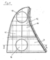
- FIGS. 1 and 2 show a tail light for vehicles which has a plurality of light chambers 1.
- the lamp chambers 1 are formed by a common light housing 2 and a common lens 3.
- the light housing 2 and the closure plate 3 are molded from plastic.
- the closure plate 3 has a red-colored frame-like base body 12, in whose window light disk sections 13, 14, 15 and 16 are injected for braking, closing, reversing and flashing light.
- the light disk section 16 is colored yellow and optically free.
- the area 5 of the frame-like basic body 12 surrounding the yellow light-disk section 16 is designed without any optics.
- the light housing 2 has a bowl-shaped reflector 7 assigned to the yellow light disk section 16, which is formed by the rear side of the light housing 2.
- the back of the light housing 2 has adjacent to the cup-shaped reflector 7 flattened wall sections 8, between which the reflector 7 is arranged.
- the wall sections 8 extend vertically and in the vehicle longitudinal direction.
- One of the two wall sections is made longer and its the lamp chamber 1 facing inner surface 11 is provided with optical surfaces 6, which faces the oblique light disc portion and having on its outer side a mirrored reflection layer. This reflection layer merges into the mirrored reflection layer of the dish-shaped reflector 7.
- the lamp chamber 1 limiting wall portion 8 is directed with its optical surfaces 6 to the vehicle side, when the lamp is mounted on the vehicle.
- the optics surfaces 6 provided with the reflection layer thus serve, together with the yellow light disk section 16, as a side reflectors limiting the vehicle side.
- the light housing 2 has, adjacent to the lamp chamber 1, a flat wall section 8 formed by the rear side of the light housing 2, which runs vertically and transversely to the vehicle longitudinal axis.
- This wall section 8 is assigned to the red-colored area 5 of the closure disk 3 and, on the side facing the area 5, likewise has optical surfaces 6 with an outer reflection layer.
- the two provided with optical surfaces 6 flat wall sections 8 and the reflector 7 have on the end plate 3 side facing a coherent reflection layer.
- lamp 17 is used for brake light and the lamp chamber 1 associated region 5 of the lens 3 is colored red.
- the red-colored area 5 extends below the lamp chamber 1 and covers a formed on the front edge portion of the reflector 7 flat wall portion 8, which on the red area facing Side with optical surfaces 6 is occupied, which together with the reflector 6 have a coherent mirrored layer.
- the optical surfaces 6 are formed by cube corners 20 and have a reflection layer.
- the wall section 8 and the reflectors 7 are formed by the back of a light housing 2.
- the cube corners 20 have perpendicular to the main surface of the reflector 4 seen a rectangular projection surface with the outer dimensions 8mm and 14mm.
- the optical elements formed by the cube corners 20 are arranged in rows. In the rear light only two juxtaposed rows are necessary because of the very large exported optical elements. Furthermore, the reflector appears brilliant because of the large optical elements from many directions. So that the large cube corners 20 have no sink marks on their optical surfaces 6 due to an accumulation of material, they are provided on their rear side with a cavity 21. Due to the cavity 21, the cube corners 20 have on their sides an equal thickness wall thickness.
Landscapes
- Engineering & Computer Science (AREA)
- General Engineering & Computer Science (AREA)
- Mechanical Engineering (AREA)
- Non-Portable Lighting Devices Or Systems Thereof (AREA)
- Lighting Device Outwards From Vehicle And Optical Signal (AREA)
- Arrangements Of Lighting Devices For Vehicle Interiors, Mounting And Supporting Thereof, Circuits Therefore (AREA)
Description
Die Erfindung betrifft eine lichttechnische Einrichtung für Fahrzeuge insbesondere Leuchte für Fahrzeuge mit dem Merkmalen nach dem Oberbegriff des Anspruchs.The invention relates to a lighting device for vehicles, in particular light for vehicles with the features according to the preamble of the claim.
Eine solche lichttechnische Einrichtung für Fahrzeuge ist aus der JP - A - 03252001 bekannt. Die Einrichtung ist eine Heckleuchte für Fahrzeuge mit einem Lichtgehäuse und einer das Lichtgehäuse abdeckenden lichtdurchlässigen Abschlussscheibe. Im Inneren der Heckleuchte ist ein Rückstrahler auf einem separaten Teil angeordnet, das an der Rückseite des Lichtgehäuses angebracht ist. Dem Rückstrahler ist ein optikfreier und glatter Bereich der Abschlussscheibe zugeordnet. Das den Rückstrahler aufweisende separate Teil weist auf der der Abschlussscheibe zugewandten Seite Optikflächen des Rückstrahlers auf, die mit einer Reflexionsschicht versehen sind. Die Optikflächen sind so ausgebildet, dass Lichtstrahlen, die auf die Optikflächen auftreffen, in ihre Einfallsrichtung zurück reflektiert werden. Diese Optikflächen des Rückstrahler sind, wie bei sonst an Kraftfahrzeugen oder Fahrrädern üblichen Rückstrahlen, die aus lichtdurchlässigen Material hergestellt sind und bei denen die Optikflächen auf der der Abschlussscheibe abgewandten Seite angeordnet sind, so klein ausgeführt, dass für einen Betrachter der Leuchte der Rückstrahler, wie üblich, als brillante, klein strukturierte Oberfläche zu sehen ist. Diese bekannten Rückstrahler sind im Volksmund unter dem Begriff "Katzenauge" bekannt.Such a lighting device for vehicles is known from JP-A-03252001. The device is a rear light for vehicles with a light housing and a translucent lens covering the light housing. Inside the rear lamp, a reflector is placed on a separate part, which is attached to the back of the light housing. The reflector has an optically clear and smooth area of the lens. The separate part having the retroreflector has optical surfaces of the retroreflector on the side facing the lens, which are provided with a reflection layer. The optical surfaces are designed such that light rays which strike the optical surfaces are reflected back in their direction of incidence. These optics surfaces of the reflector are, as in otherwise customary to motor vehicles or bicycles back rays, which are made of translucent material and in which the optics surfaces are arranged on the side facing away from the lens, so small designed that for a viewer of the lamp reflectors, such as common, as a brilliant, small textured surface can be seen. These known reflectors are popularly known by the term "cat's eye".
Eine lichttechnische Einrichtung für Fahrzeuge ist aus der DE 198 23 106 A1 bekannt. Als lichttechnische Einrichtung dient eine Leuchte, die mehrere Leuchtenkammern aufweist. Die Leuchtenkammern sind von einem aus Kunststoff bestehenden gemeinsamen Lichtgehäuse und einer das Lichtgehäuse abdeckenden Abschlußscheibe gebildet. Die Rückseite des Lichtgehäuses selbst bilden schalenförmige Reflektoren, denen jeweils eine Lampe zugeordnet ist. Die Abschlußscheibe besteht aus mehreren aneinander gespritzten Lichtscheibenabschnitten, die unterschiedlich eingefärbt sind. Einer Lichtkammer ist ein rot eingefärbter Lichtscheibenabschnitt zugeordnet, an dem eine einen Rückstrahler halternde Abdichtplatte durch Ultraschallschweißen angebracht ist. Der Rückstrahler ist von einer Zwischenscheibe gebildet, die von der Abdichtplatte auf der der Abschlußscheibe zugewandten Seite gehaltert ist. Die Zwischenscheibe weist auf der der Abschlußscheibe abgewandten Seite rückstrahlende Optikflächen auf, welche zum Beispiel von Tripeln oder Würfelekken gebildet sind und welche von außen durch die Abschlußscheibe hindurchtretende und in die Zwischenscheibe eintretende Lichtstrahlen total reflektieren. Ein zur Zwischenscheibe benachbart verlaufender Abschnitt der Abschlußscheibe weist außen und innen eine glatte Oberfläche auf. Hierbei ist es nachteilig, daß der Rückstrahler selbst und die Abdichtplatte ein zusätzliches Teil sind und für das Festsitzen der Abdichtplatte an der Abschlußscheibe ein gesondertes Verfahren, wie zum Beispiel Ultraschallschweißen, notwendig ist.A lighting device for vehicles is known from DE 198 23 106 A1. As a lighting device is a lamp which has a plurality of lamp chambers. The lamp chambers are formed by a plastic light common housing and a light housing covering the cover plate. The back of the light housing itself form cup-shaped reflectors, each associated with a lamp. The lens consists of several sprayed together lens sections, which are colored differently. A light chamber is associated with a red-colored lens section, to which a reflector plate holding a reflector is attached by ultrasonic welding. The retroreflector is formed by an intermediate disc, which is supported by the sealing plate on the side facing the lens. The intermediate disc has on the side facing away from the lens side retroreflective optic surfaces, which are formed for example by triples or cube-keks and which totally from the outside passing through the lens and entering into the washer light rays reflect. An adjacent to the washer adjacent portion of the lens has outside and inside a smooth surface. It is disadvantageous that the reflector itself and the sealing plate are an additional part and a separate method, such as ultrasonic welding, is necessary for the seizing of the sealing plate to the lens.
Weiterhin kann ein in dieser Art an der Abschlußscheibe angebrachter Rückstrahler aus optischen Gründen unerwünscht sein, da die Anbindungsstellen von der den Rückstrahler halternden Abdichtplatte von außen deutlich zu sehen sind.Furthermore, a reflector mounted in this manner on the lens disc may be undesirable for optical reasons, since the attachment sites are clearly visible from the outside of the sealing plate holding the retroreflector.
Aufgabe der Erfindung ist es, die im Oberbegriff des Anspruchs 1 beschriebene Leuchte für Fahrzeuge derart zu gestalten, dass für einen Betrachter der Einrichtung der Rückstrahler ein vom üblichen abweichendes Erscheinungsbild aufweist und trotzdem weiterhin die Funktion des Rückstrahlers sicher ist. Diese Aufgabe wird nach der Erfindung durch die Merkmale des kennzeichnenden Teils des Anspruchs 1 gelöst.The object of the invention is to make the lamp described in the preamble of
Der Rückstrahler kann aus lichtdurchlässigem oder opakem Werkstoff bestehen. Somit kann ein den Rückstrahler aufweisender Wandabschnitt einstückig mit einem Reflektor oder einer Abdeckblende ausgeführt sein. In diesem Zusammenhang ist es vorteilhaft, wenn die Reflexionsschicht der Optikflächen in einer Reflexionsschicht des Reflektors bzw. eine verspiegelte Oberfläche der Abdeckblende übergeht. Dadurch entfällt ein zusätzliches Aufbringen der Reflexionsschicht auf die Optikflächen des Rückstrahlers. Der Rückstrahler kann auch von einem Wandabschnitt des Lichtgehäuses gebildet sein.The reflector can be made of translucent or opaque material. Thus, a wall section having the retroreflector can be made in one piece with a reflector or a cover panel. In this context It is advantageous if the reflection layer of the optical surfaces merges into a reflection layer of the reflector or a mirrored surface of the cover panel. This eliminates an additional application of the reflection layer on the optical surfaces of the reflector. The retroreflector can also be formed by a wall portion of the light housing.
Der den Rückstrahler bildende Wandabschnitt dient zusätzlich als Abdeckblende, wenn er benachbart zur Lichtaustrittsöffnung des Reflektors verläuft und an den vorderen Randabschnitt des Reflektors angeformt ist und sich bis zu einem vorderen Randabschnitt des Lichtgehäuses hin erstreckt. Dadurch kann der Reflektor in seinem die Lichtaustrittsfläche begrenzenden Rand beliebig geformt sein.The wall portion forming the retroreflector additionally serves as a cover panel when it is adjacent to the light exit opening of the reflector and is integrally formed with the front edge portion of the reflector and extends up to a front edge portion of the light housing. As a result, the reflector can be shaped as desired in its edge delimiting the light exit surface.
Bei einem eine Fahrzeugsseite markierenden Rückstrahler ist es vorteilhaft, wenn dieser in eine Blinkleuchte integriert ist und an einer zur Fahrzeugseite hin gerichteten Oberfläche eines seitlichen Wandabschnitts der Blinkleuchte angeordnet ist. Die Reflexionsschicht der Optikflächen des Rückstrahlers und die Reflexionsfläche des Reflektors sind zusammen auf einen Reflektor aufbringbar, wenn der seitliche Wandabschnitt einstückig an den Reflektor angeformt ist. Hierbei kann die Abschlußscheibe der Blinkleuchte bzw. eine im Innem der Blinkleuchte angeordnete Zwischenscheibe gelb eingefärbt ein.In the case of a rear reflector which marks a vehicle side, it is advantageous if it is integrated in a flashing light and is arranged on a surface of a lateral wall section of the flashing light directed toward the vehicle side. The reflection layer of the optical surfaces of the reflector and the reflection surface of the reflector can be applied together to a reflector when the lateral wall portion is integrally formed on the reflector. Here, the lens of the turn signal or arranged in the interior of the turn signal washer can be colored yellow.
Die lichttechnische Einrichtung kann von einem Scheinwerfer, einer vorderen Blinkleuchte, einer Heckleuchte oder ein Seitenmarkierungsrückstrahler gebildet sein.The lighting device may be formed by a headlight, a front turn signal, a taillight or a side marker reflector.
Zwei Ausführungsbeispiele nach der Erfindung sind in der Zeichnung dargestellt und zeigen:
Figur 1 in einer Vorderansicht eine Heckleuchte für Fahrzeuge mit mehreren Leuchtenkammern;Figur 2 einen Schnitt nach der Linie A-A durch eine Blinkleuchte der Heckleuchte inFigur 1 mit einem roten und gelben Rückstrahler;Figur 3 in einer Vorderansicht eine andere Heckleuchte für Fahrzeuge,Figur 4 in einem Schnitt nach der Linie B-B inFigur 3 eine Schlußleuchte mit einem roten RückstrahlerFigur 5 in einer Vorderansicht eine weitere Heckleuchte für Fahrzeuge,Figur 6 einen Schnitt nach der Linie C-C inFigur 5 durch einen Rückstrahler in vergrößerten Maßstab undFigur 7 in einer Vorderansicht einen Teil des Rückstrahlers vonFigur 5 und 6.
- Figure 1 is a front view of a tail light for vehicles with multiple lighting chambers;
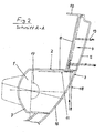
- Figure 2 is a section along the line AA through a flashing light of the tail light in Figure 1 with a red and yellow reflector;
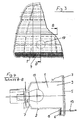
- FIG. 3 is a front view of another rear lamp for vehicles;
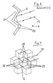
- Figure 4 in a section along the line BB in Figure 3 a taillight with a red reflector
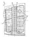
- FIG. 5 shows a front view of a further tail lamp for vehicles;
- 6 shows a section along the line CC in Figure 5 by a reflector on an enlarged scale and
- FIG. 7 is a front view of part of the retroreflector of FIGS. 5 and 6.
In den Figuren 1 und 2 ist eine Heckleuchte für Fahrzeuge dargestellt, welche mehrere Leuchtenkammern 1 aufweist. Die Leuchtenkammern 1 sind von einem gemeinsamen Lichtgehäuse 2 und einer gemeinsamen Abschlußscheibe 3 gebildet. Das Lichtgehäuse 2 und die Abschlußscheibe 3 sind aus Kunststoff geformt. Die Abschlußscheibe 3 weist einen rot eingefärbten rahmenartigen Grundkörper 12 auf, in dessen Fenster Lichtscheibenabschnitte 13, 14, 15 und 16 für Brems-, Schluß-, Rückfahr- und Blinklicht eingespritzt sind. Der Lichtscheibenabschnitt 16 ist gelb eingefärbt und optikfrei ausgeführt. Ebenso ist der den gelben Lichtscheibenabschnitt 16 umgebende Bereich 5 des rahmenartigen Grundkörpers 12 optikfrei ausgeführt. Das Lichtgehäuse 2 weist einen dem gelben Lichtscheibenabschnitt 16 zugeordneten schalenförmigen Reflektor 7 auf, der von der Rückseite des Lichtgehäuses 2 gebildet ist. In dem Scheitelbereich des Reflektors 7 ist eine Öffnung zur Aufnahme einer Lampe 17 eingebracht. Die Rückseite des Lichtgehäuse 2 weist angrenzend an den schalenförmigen Reflektor 7 abgeflachte Wandabschnitte 8 auf, zwischen welchen der Reflektor 7 angeordnet ist. Die Wandabschnitte 8 verlaufen vertikal und in Fahrzeuglängsrichtung. Einer der beiden Wandabschnitte ist länger ausgeführt und seine der Leuchtenkammer 1 zugewandte innere Oberfläche 11 ist mit Optikflächen 6 versehen, welche dem schräg verlaufenden Lichtscheibenabschnitt zugewandt ist und auf ihrer Außenseite eine verspiegelte Reflexionsschicht aufweist. Diese Reflexionsschicht geht in die verspiegelte Reflexionsschicht des schalenförmigen Reflektors 7 über. Der die Leuchtenkammer 1 begrenzende Wandabschnitt 8 ist mit seinen Optikflächen 6 zur Fahrzeugseite hin gerichtet, wenn die Leuchte am Fahrzeug angebaut ist. Seitlich von außen durch den gelben Lichtscheibenabschnitt 16 fallende Lichtstrahlen 18 werden durch eine Reflexion an der Reflexionsschicht der Optikflächen 6 um 180° umgelenkt. Die mit der Reflexionsschicht versehenen Optikflächen 6 dienen somit zusammen mit dem gelben Lichtscheibenabschnitt 16 als ein die Fahrzeugseite begrenzenden seitlichen Rückstrahler. Das Lichtgehäuse 2 weist angrenzend an die Leuchtenkammer 1 einen von der Rückseite des Lichtgehäuses 2 gebildeten ebenen Wandabschnitt 8 auf, welcher vertikal und quer zur Fahrzeuglängsachse verläuft. Dieser Wandabschnitt 8 ist dem rot eingefärbten Bereich 5 der Abschlußscheibe 3 zugeordnet und weist auf der dem Bereich 5 zugewandten Seite ebenfalls Optikflächen 6 mit einer äußeren Reflexionsschicht auf. An diesen Optikflächen 6 werden die von außen durch den roten Bereich 5 hindurchtretenden Lichtstrahlen durch Reflexion um 180° umgelenkt. Die beiden mit Optikflächen 6 versehenen ebenen Wandabschnitte 8 und der Reflektor 7 weisen auf der der Abschlußscheibe 3 zugewandten Seite eine zusammenhängende Reflexionsschicht auf.FIGS. 1 and 2 show a tail light for vehicles which has a plurality of
Bei der in den Figuren 3 und 4 dargestellten Heckleuchte dient die in der Leuchtenkammer 1 angeordnete Lampe 17 für Bremslicht und der der Leuchtenkammer 1 zugeordnete Bereich 5 der Abschlußscheibe 3 ist rot eingefärbt. Der rot eingefärbte Bereich 5 erstreckt sich bis unterhalb der Leuchtenkammer 1 und deckt einen an den vorderen Randabschnitt des Reflektors 7 angeformten ebenen Wandabschnitt 8 ab, der auf der dem roten Bereich zugewandten Seite mit Optikflächen 6 besetzt ist, die zusammen mit dem Reflektor 6 eine zusammenhängende verspiegelte Schicht aufweisen.In the rear light shown in Figures 3 and 4, arranged in the
Bei der in den Figuren 5 bis 7 dargestellten Heckleuchte ist zwischen Reflektoren 7 ein Wandabschnitt 8 angeordnet, der Optikflächen 6 eines Rückstrahlers 4 aufweist. Die Optikflächen 6 sind von Würfelecken 20 gebildet und weisen eine Reflexionsschicht auf. Der Wandabschnitt 8 und die Reflektoren 7 sind von der Rückseite eines Lichtgehäuses 2 gebildet. Die Würfelecken 20 weisen senkrecht zur Hauptfläche des Rückstrahlers 4 gesehen eine rechteckige Projektionsfläche auf mit den Außenmaßen 8mm und 14mm. Die von den Würfelecken 20 gebildeten Optikelemente sind in Zeilen angeordnet. Bei der Heckleuchte sind wegen den sehr groß ausgeführten Optikelementen nur zwei nebeneinander angeordnete Zeilen notwendig. Weiterhin erscheint der Rückstrahler wegen den großen Optikelementen aus vielen Richtungen brillant. Damit die großen Würfelecken 20 wegen einer Materialanhäufung keine Einfallstellen an ihren Optikflächen 6 aufweisen, sind diese auf ihrer Rückseite mit einem Hohlraum 21 versehen. Bedingt durch den Hohlraum 21 weisen die Würfelecken 20 an ihren Seiten eine gleich dicke Wandstärke aufweisen.In the rear light illustrated in FIGS. 5 to 7, a
- 1.1.
- Leuchtenkammernlights chambers
- 2.Second
- Lichtgehäuselight housing
- 3.Third
- Abschlußscheibecover screen
- 4.4th
- Rückstrahlerreflector
- 5.5th
- BereichArea
- 6.6th
- Optikflächenoptical surfaces
- 7.7th
- Reflektorreflector
- 8.8th.
- Wandabschnittwall section
- 9.9th
- LichtaustrittsöffnungLight opening
- 10.10th
- Randabschnittedge section
- 11.11th
- Oberflächesurface
- 12.12th
- Grundkörperbody
- 13.13th
- LichtscheibenabschnittLens Section
- 14.14th
- LichtscheibenabschnittLens Section
- 15.15th
- LichtscheibenabschnittLens Section
- 16.16th
- LichtscheibenabschnittLens Section
- 17.17th
- Lampelamp
- 18.18th
- Lichtstrahlenlight rays
- 19.19th
- Lichtstrahlenlight rays
- 20.20th
- Würfeleckencube corners
- 21.21st
- Hohlraumcavity
Claims (10)
- Vehicle lighting assembly, in particular a lamp for motor vehicles, comprising a lamp housing (2) with a transparent front pane (3) and a reflex reflector (4) arranged inside the assembly, which reflex reflector (4) is provided on one side with a multiplicity of lens faces, the front pane (3) having at least one lens-free smooth area (5) for the reflex reflector (4), the side of the reflex reflector that has the lens faces (6) facing towards the front pane (3) and the reflex reflector having on this side a reflective coating by which light rays (18, 19) are reflected back into their incident direction after multiple reflection, characterised in that the lens faces of the reflex reflector (4) are formed by side faces adjacent to a corner of a cube, which side faces have an equal wall thickness while the corner of the cube has a dimension of at least 6 mm.
- Lighting assembly according to claim 1, characterised in that at least the smooth area (5) of the front pane (3) with which the reflex reflector (4) is associated has a colour that determines the colour tone of the reflex reflector (4).
- Lighting assembly according to claim 1 or 2, characterised in that the lens faces (6) are formed by a wall section (8) constructed in one piece with a reflector (7) and the reflector (7) and the wall section (8) are made of opaque material and have a continuous reflective coating.
- Lighting assembly according to claim 3, characterised in that the wall section (8) having the lens faces (6) is disposed adjacent to the light exit aperture of the reflector (7).
- Lighting assembly according to claim 4, characterised in that the wall section (8) provided with the lens faces (6) surrounds the reflector (7) at least partially and extends up to a front edge section (10) of the lamp housing (2).
- Lighting assembly according to claim 3, characterised in that in the case of a direction indicator that can be arranged in the corner region of a vehicle a surface (11) of a lateral wall section (8) facing to the side of the vehicle is provided with the lens faces (6).
- Lighting assembly according to any one of claims 3 to 6, characterised in that the wall section (8) having the lens faces (6) and the reflector (7) are formed by the rear face of the lamp housing (2).
- Lighting assembly according to any one of claims 3 to 6, characterised in that the wall section (8) is manufactured from a different material to that of the part supporting it.
- Lighting assembly according to claim 1 or 2, characterised in that an occluding screen arranged inside the assembly has the lens faces on a wall section on a side facing towards the front pane, the lens faces and the occluding screen being provided with a continuous reflective coating.
- Lighting assembly according to claim 1 or 2, characterised in that the lamp housing (2) has the lens faces (6) on a wall section (8).
Applications Claiming Priority (2)
| Application Number | Priority Date | Filing Date | Title |
|---|---|---|---|
| DE19946850A DE19946850A1 (en) | 1999-09-30 | 1999-09-30 | Lighting equipment for vehicles |
| DE19946850 | 1999-09-30 |
Publications (3)
| Publication Number | Publication Date |
|---|---|
| EP1089033A2 EP1089033A2 (en) | 2001-04-04 |
| EP1089033A3 EP1089033A3 (en) | 2003-11-05 |
| EP1089033B1 true EP1089033B1 (en) | 2006-04-26 |
Family
ID=7923829
Family Applications (1)
| Application Number | Title | Priority Date | Filing Date |
|---|---|---|---|
| EP00119707A Expired - Lifetime EP1089033B1 (en) | 1999-09-30 | 2000-09-09 | Vehicle lighting assembly |
Country Status (4)
| Country | Link |
|---|---|
| US (1) | US6409368B1 (en) |
| EP (1) | EP1089033B1 (en) |
| DE (2) | DE19946850A1 (en) |
| ES (1) | ES2262475T3 (en) |
Families Citing this family (11)
| Publication number | Priority date | Publication date | Assignee | Title |
|---|---|---|---|---|
| US6612382B2 (en) * | 1996-03-25 | 2003-09-02 | Halliburton Energy Services, Inc. | Iterative drilling simulation process for enhanced economic decision making |
| DE10037005A1 (en) | 2000-07-29 | 2002-02-07 | Hella Kg Hueck & Co | Light for vehicles |
| US20040216406A1 (en) * | 2001-10-31 | 2004-11-04 | Ken Egashira | Decorative structure |
| US7137718B2 (en) * | 2001-10-31 | 2006-11-21 | 3M Innovative Properties Company | Automotive lamp |
| US7175293B2 (en) * | 2001-11-02 | 2007-02-13 | 3M Innovative Properties Company | Decorative article and vehicular lamp |
| US7077550B2 (en) * | 2001-11-02 | 2006-07-18 | 3M Innovative Properties Company | Automotive lamp with light transmissive colored member |
| DE10246945B4 (en) * | 2002-10-08 | 2007-07-19 | Hella Kgaa Hueck & Co. | Vehicle lamp with reflector element |
| DE102006007101A1 (en) * | 2005-09-12 | 2007-03-22 | Kompled Gmbh & Co. Kg | Tail light assembly, especially for commercial vehicles |
| EP1854705B1 (en) * | 2006-05-10 | 2009-07-15 | Mazda Motor Corporation | Vehicle body structure |
| DE102009021983A1 (en) * | 2009-05-19 | 2010-11-25 | Hella Kgaa Hueck & Co. | Lamp for vehicles |
| DE102014211789A1 (en) * | 2014-06-19 | 2015-12-24 | Volkswagen Aktiengesellschaft | Lighting device with retroreflective element for a motor vehicle and a motor vehicle |
Family Cites Families (13)
| Publication number | Priority date | Publication date | Assignee | Title |
|---|---|---|---|---|
| US1412470A (en) * | 1920-09-21 | 1922-04-11 | Waller L Kaufmann | Automobile headlight |
| ES473582A1 (en) * | 1977-09-29 | 1979-05-01 | Rau Swf Autozubehoer | Signal lamp |
| IT1156906B (en) * | 1978-02-27 | 1987-02-04 | Iao Industrie Riunite Spa | MOTORCYCLE LIGHT |
| EP0097449B1 (en) * | 1982-06-19 | 1986-04-09 | Britax Vega Limited | Vehicle lamp assembly |
| US4912606A (en) * | 1987-10-28 | 1990-03-27 | Koito Manufacturing Co., Ltd. | Vehicle lamp device |
| DE9001659U1 (en) * | 1990-02-13 | 1990-04-19 | Hella Kg Hueck & Co, 4780 Lippstadt, De | |
| JPH03252001A (en) * | 1990-03-01 | 1991-11-11 | Stanley Electric Co Ltd | Vehicle signal lighting fixture |
| JPH0821244B2 (en) * | 1990-06-19 | 1996-03-04 | 株式会社小糸製作所 | Automotive headlamp |
| JP2787415B2 (en) * | 1994-03-28 | 1998-08-20 | 株式会社小糸製作所 | Vehicle sign lights |
| JP3607019B2 (en) * | 1996-10-17 | 2005-01-05 | 株式会社小糸製作所 | Vehicle lamp |
| JP3919880B2 (en) * | 1997-05-22 | 2007-05-30 | 株式会社小糸製作所 | Vehicle lamp |
| JP3337125B2 (en) * | 1998-01-23 | 2002-10-21 | スタンレー電気株式会社 | Vehicle light with reflex reflector |
| DE19807409A1 (en) * | 1998-02-21 | 1999-08-26 | Volkswagen Ag | Headlamp or light for motor vehicle |
-
1999
- 1999-09-30 DE DE19946850A patent/DE19946850A1/en not_active Withdrawn
-
2000
- 2000-09-09 ES ES00119707T patent/ES2262475T3/en not_active Expired - Lifetime
- 2000-09-09 DE DE50012638T patent/DE50012638D1/en not_active Expired - Lifetime
- 2000-09-09 EP EP00119707A patent/EP1089033B1/en not_active Expired - Lifetime
- 2000-10-02 US US09/676,510 patent/US6409368B1/en not_active Expired - Lifetime
Also Published As
| Publication number | Publication date |
|---|---|
| EP1089033A3 (en) | 2003-11-05 |
| DE50012638D1 (en) | 2006-06-01 |
| US6409368B1 (en) | 2002-06-25 |
| EP1089033A2 (en) | 2001-04-04 |
| ES2262475T3 (en) | 2006-12-01 |
| DE19946850A1 (en) | 2001-04-05 |
Similar Documents
| Publication | Publication Date | Title |
|---|---|---|
| EP0442095B1 (en) | Rearlight for vehicles | |
| EP0955207B1 (en) | Multi-compartment light for motor vehicles | |
| EP0780265B1 (en) | Vehicle rear light | |
| DE4417695C2 (en) | Motor vehicle light | |
| EP1914118B1 (en) | External rear mirror with illumination device | |
| EP1089033B1 (en) | Vehicle lighting assembly | |
| DE3843522C2 (en) | ||
| DE19624244B4 (en) | Lamp for vehicles | |
| DE3305218C2 (en) | Multi-chamber light for motor vehicles | |
| DE3126554A1 (en) | LIGHTING DEVICE FOR MOTOR VEHICLES | |
| DE10101789B4 (en) | Lighting device, in particular headlight or headlight assembly of a motor vehicle | |
| DE3828522C2 (en) | Motor vehicle light | |
| DE19646042A1 (en) | Lighting device for motor vehicle | |
| DE10033776B4 (en) | Headlight for a motor vehicle | |
| DE69915716T2 (en) | Lamp with reflector for vehicles | |
| DE3306481A1 (en) | Light-emitting device for motor vehicles | |
| EP1079171A2 (en) | Flashing light for vehicles | |
| DE3427398C2 (en) | ||
| EP1224419B1 (en) | Headlight for a motor vehicle | |
| DE3841501A1 (en) | VEHICLE LIGHT, ESPECIALLY FOG LIGHT OR REVERSE LIGHT | |
| DE10101794A1 (en) | Illumination device, especially headlamp or lamp unit for motor vehicles, has flexible housing and/or panel region in longitudinal direction that can be deformed by shock load on panel | |
| DE102011113627B4 (en) | Lens for a vehicle light and vehicle people with such a lens | |
| DE10241023A1 (en) | Rear light for road vehicle has incandescent lamp in center of mirror behind lens with multiple refracting elements producing appearance of array of LED's | |
| DE19727982A1 (en) | Light for vehicles | |
| DE3633662A1 (en) | Lens for front headlamps or the like for fitting in vehicles |
Legal Events
| Date | Code | Title | Description |
|---|---|---|---|
| PUAI | Public reference made under article 153(3) epc to a published international application that has entered the european phase |
Free format text: ORIGINAL CODE: 0009012 |
|
| AK | Designated contracting states |
Kind code of ref document: A2 Designated state(s): AT BE CH CY DE DK ES FI FR GB GR IE IT LI LU MC NL PT SE |
|
| AX | Request for extension of the european patent |
Free format text: AL;LT;LV;MK;RO;SI |
|
| PUAL | Search report despatched |
Free format text: ORIGINAL CODE: 0009013 |
|
| AK | Designated contracting states |
Kind code of ref document: A3 Designated state(s): AT BE CH CY DE DK ES FI FR GB GR IE IT LI LU MC NL PT SE |
|
| AX | Request for extension of the european patent |
Extension state: AL LT LV MK RO SI |
|
| 17P | Request for examination filed |
Effective date: 20040410 |
|
| 17Q | First examination report despatched |
Effective date: 20040601 |
|
| AKX | Designation fees paid |
Designated state(s): DE ES FR IT |
|
| RAP1 | Party data changed (applicant data changed or rights of an application transferred) |
Owner name: HELLA KGAA HUECK & CO. |
|
| GRAP | Despatch of communication of intention to grant a patent |
Free format text: ORIGINAL CODE: EPIDOSNIGR1 |
|
| GRAS | Grant fee paid |
Free format text: ORIGINAL CODE: EPIDOSNIGR3 |
|
| GRAA | (expected) grant |
Free format text: ORIGINAL CODE: 0009210 |
|
| AK | Designated contracting states |
Kind code of ref document: B1 Designated state(s): DE ES FR IT |
|
| REF | Corresponds to: |
Ref document number: 50012638 Country of ref document: DE Date of ref document: 20060601 Kind code of ref document: P |
|
| REG | Reference to a national code |
Ref country code: ES Ref legal event code: FG2A Ref document number: 2262475 Country of ref document: ES Kind code of ref document: T3 |
|
| ET | Fr: translation filed | ||
| PLBE | No opposition filed within time limit |
Free format text: ORIGINAL CODE: 0009261 |
|
| STAA | Information on the status of an ep patent application or granted ep patent |
Free format text: STATUS: NO OPPOSITION FILED WITHIN TIME LIMIT |
|
| 26N | No opposition filed |
Effective date: 20070129 |
|
| PGFP | Annual fee paid to national office [announced via postgrant information from national office to epo] |
Ref country code: IT Payment date: 20110915 Year of fee payment: 12 |
|
| PG25 | Lapsed in a contracting state [announced via postgrant information from national office to epo] |
Ref country code: IT Free format text: LAPSE BECAUSE OF NON-PAYMENT OF DUE FEES Effective date: 20120909 |
|
| PGFP | Annual fee paid to national office [announced via postgrant information from national office to epo] |
Ref country code: ES Payment date: 20150810 Year of fee payment: 16 |
|
| REG | Reference to a national code |
Ref country code: FR Ref legal event code: PLFP Year of fee payment: 17 |
|
| REG | Reference to a national code |
Ref country code: FR Ref legal event code: PLFP Year of fee payment: 18 |
|
| REG | Reference to a national code |
Ref country code: DE Ref legal event code: R079 Ref document number: 50012638 Country of ref document: DE Free format text: PREVIOUS MAIN CLASS: F21S0008100000 Ipc: F21S0043000000 |
|
| REG | Reference to a national code |
Ref country code: DE Ref legal event code: R081 Ref document number: 50012638 Country of ref document: DE Owner name: HELLA GMBH CO. KGAA, DE Free format text: FORMER OWNER: HELLA KGAA HUECK CO., 59557 LIPPSTADT, DE Ref country code: DE Ref legal event code: R081 Ref document number: 50012638 Country of ref document: DE Owner name: HELLA GMBH & CO. KGAA, DE Free format text: FORMER OWNER: HELLA KGAA HUECK & CO., 59557 LIPPSTADT, DE |
|
| REG | Reference to a national code |
Ref country code: DE Ref legal event code: R084 Ref document number: 50012638 Country of ref document: DE |
|
| PG25 | Lapsed in a contracting state [announced via postgrant information from national office to epo] |
Ref country code: ES Free format text: LAPSE BECAUSE OF NON-PAYMENT OF DUE FEES Effective date: 20160910 |
|
| REG | Reference to a national code |
Ref country code: FR Ref legal event code: PLFP Year of fee payment: 19 |
|
| PGFP | Annual fee paid to national office [announced via postgrant information from national office to epo] |
Ref country code: FR Payment date: 20180813 Year of fee payment: 19 Ref country code: DE Payment date: 20180828 Year of fee payment: 19 |
|
| REG | Reference to a national code |
Ref country code: ES Ref legal event code: FD2A Effective date: 20181121 |
|
| REG | Reference to a national code |
Ref country code: DE Ref legal event code: R119 Ref document number: 50012638 Country of ref document: DE |
|
| PG25 | Lapsed in a contracting state [announced via postgrant information from national office to epo] |
Ref country code: DE Free format text: LAPSE BECAUSE OF NON-PAYMENT OF DUE FEES Effective date: 20200401 |
|
| PG25 | Lapsed in a contracting state [announced via postgrant information from national office to epo] |
Ref country code: FR Free format text: LAPSE BECAUSE OF NON-PAYMENT OF DUE FEES Effective date: 20190930 |