EP1086844A2 - Road shape estimation apparatus and curve approach control apparatus - Google Patents
Road shape estimation apparatus and curve approach control apparatus Download PDFInfo
- Publication number
- EP1086844A2 EP1086844A2 EP00308220A EP00308220A EP1086844A2 EP 1086844 A2 EP1086844 A2 EP 1086844A2 EP 00308220 A EP00308220 A EP 00308220A EP 00308220 A EP00308220 A EP 00308220A EP 1086844 A2 EP1086844 A2 EP 1086844A2
- Authority
- EP
- European Patent Office
- Prior art keywords
- node
- curve
- radius
- nodes
- interval
- Prior art date
- Legal status (The legal status is an assumption and is not a legal conclusion. Google has not performed a legal analysis and makes no representation as to the accuracy of the status listed.)
- Granted
Links
Images


Classifications
-
- B—PERFORMING OPERATIONS; TRANSPORTING
- B60—VEHICLES IN GENERAL
- B60K—ARRANGEMENT OR MOUNTING OF PROPULSION UNITS OR OF TRANSMISSIONS IN VEHICLES; ARRANGEMENT OR MOUNTING OF PLURAL DIVERSE PRIME-MOVERS IN VEHICLES; AUXILIARY DRIVES FOR VEHICLES; INSTRUMENTATION OR DASHBOARDS FOR VEHICLES; ARRANGEMENTS IN CONNECTION WITH COOLING, AIR INTAKE, GAS EXHAUST OR FUEL SUPPLY OF PROPULSION UNITS IN VEHICLES
- B60K31/00—Vehicle fittings, acting on a single sub-unit only, for automatically controlling vehicle speed, i.e. preventing speed from exceeding an arbitrarily established velocity or maintaining speed at a particular velocity, as selected by the vehicle operator
- B60K31/0066—Vehicle fittings, acting on a single sub-unit only, for automatically controlling vehicle speed, i.e. preventing speed from exceeding an arbitrarily established velocity or maintaining speed at a particular velocity, as selected by the vehicle operator responsive to vehicle path curvature
-
- B—PERFORMING OPERATIONS; TRANSPORTING
- B60—VEHICLES IN GENERAL
- B60W—CONJOINT CONTROL OF VEHICLE SUB-UNITS OF DIFFERENT TYPE OR DIFFERENT FUNCTION; CONTROL SYSTEMS SPECIALLY ADAPTED FOR HYBRID VEHICLES; ROAD VEHICLE DRIVE CONTROL SYSTEMS FOR PURPOSES NOT RELATED TO THE CONTROL OF A PARTICULAR SUB-UNIT
- B60W2552/00—Input parameters relating to infrastructure
- B60W2552/20—Road profile
-
- B—PERFORMING OPERATIONS; TRANSPORTING
- B60—VEHICLES IN GENERAL
- B60W—CONJOINT CONTROL OF VEHICLE SUB-UNITS OF DIFFERENT TYPE OR DIFFERENT FUNCTION; CONTROL SYSTEMS SPECIALLY ADAPTED FOR HYBRID VEHICLES; ROAD VEHICLE DRIVE CONTROL SYSTEMS FOR PURPOSES NOT RELATED TO THE CONTROL OF A PARTICULAR SUB-UNIT
- B60W2552/00—Input parameters relating to infrastructure
- B60W2552/30—Road curve radius
Definitions
- the present invention relates to a road shape estimation apparatus to eliminate improper nodes for calculating a radius of curvature for a curve and to a curve approach speed control apparatus using the road shape estimation apparatus.
- JP-A-4-236699 proposes a vehicle traveling system which calculates an allowable approach speed for a curve in front by using data (node data) on points on the ground (nodes) shown on a road map of a navigation device, detects a speed higher than the allowable approach speed, i.e., an overspeed state for the curve in front, and issues an alarm or performs a speed reduction control.
- the applicant of this invention has proposed in JP-A-11-2528 a method for determining a radius of curvature for a curve based on a plurality of node data output from the navigation device.
- the center node and the two other nodes on both sides are connected with straight lines, and the lengths of the two straight lines are compared.
- a half the length of the shorter straight line is taken from the center node on both straight lines to find mid points.
- normal lines perpendicular to their own straight lines are drawn until they intersect each other.
- the distance from the point of intersection to each mid point is set as a radius of curvature for a curve.
- a method in JP-A-11-83501 calculates, based on a radius of curvature for a curve and a lateral acceleration, an allowable curve approach speed at which the vehicle can safely negotiate the curve in front, compares the allowable curve approach speed with the car speed in a predetermined procedure to check whether the curve can be safely negotiated, and, if the decision indicates an overspeed, issues an alarm prompting the user to decrease the speed or forcibly performs a speed reduction control as required.
- the present invention has been accomplished under these circumstances to provide a road shape estimation apparatus and a curve approach speed control apparatus using the road shape estimation apparatus, which, even when the node intervals are extremely short, can calculate a curve's radius of curvature approximating the actual curve, set an appropriate allowable curve approach speed and thereby alleviate a sense of incongruity from the driver.
- a first road shape estimation apparatus comprises inputting a plurality of node data concerning a road in front from a navigation device, calculating, based on the node data, a node interval between each node and an adjacent node and a node angle for each node, and, based on the node intervals and the node angles, calculating a curve's radius of curvature for each node, wherein the road shape estimation apparatus detects, based on the node intervals and the node angles, a node which constitutes a curve's radius of curvature calculation removal point, and calculates the curve's radius of curvature by removing the node which constitutes the curve's radius of curvature calculation removal point.
- the apparatus when inputting a plurality of node data concerning a road in front from a navigation device, calculating, based on the node data, a node interval between each node and an adjacent node and a node angle for each node, and, based on the node intervals and the node angles, calculating a curve's radius of curvature for each node, the apparatus detects, based on the node intervals and the node angles, a node which constitutes a curve's radius of curvature calculation removal point, and calculates the curve's radius of curvature by removing the node which constitutes the curve's radius of curvature calculation removal point.
- a second road shape estimation apparatus is characterized in that, in the first road shape estimation apparatus, when the node interval is equal to or less than a preset node interval, at least one of nodes at both ends of the node interval is taken as the curve's radius of curvature calculation removal point.
- a third road shape estimation apparatus is characterized in that, in the first road shape estimation apparatus, when the node interval is equal to or less than a preset node interval and bending directions of the node angles calculated at the two nodes situated at the both ends of the node interval are opposite, at least one of the two nodes is taken as the curve's radius of curvature calculation removal point.
- a fourth road shape estimation apparatus is characterized in that, in the first road shape estimation apparatus, when the node interval is equal to or less than a preset node interval and a larger one of the node angles calculated at the two nodes situated at the both ends of the node interval is equal to or more than a preset maximum threshold angle, at least one of the two nodes is taken as the curve's radius of curvature calculation removal point.
- a fifth road shape estimation apparatus is characterized in that, in the first road shape estimation apparatus, when the node interval is equal to or less than a preset node interval and a smaller one of the node angles calculated at the two nodes situated at the both ends of the node interval is equal to or less than a preset minimum threshold angle, at least one of the two nodes is taken as the curve's radius of curvature calculation removal point.
- a sixth road shape estimation apparatus is characterized in that, in the first road shape estimation apparatus, when an angle formed by a line connecting first two of four consecutive nodes and a line connecting last two nodes is equal to or less than a preset minimum threshold angle and a node interval connecting two middle nodes is equal to or less than a preset node interval, at least one of the two middle nodes is taken as the curve's radius of curvature calculation removal point.
- a seventh road shape estimation apparatus is characterized in that, in the second road shape estimation apparatus, the preset node interval is set by multiplying a preset node interval calculation coefficient by a road width coefficient.
- the preset node interval is set by multiplying a preset node interval calculation coefficient by a road width coefficient.
- a eighth road shape estimation apparatus is characterized in that, in the seventh road shape estimation apparatus, the preset node interval calculation coefficient is set for each road kind.
- the preset node interval calculation coefficient is set for each road kind.
- a ninth road shape estimation apparatus is characterized in that, in the fourth road shape estimation apparatus, the maximum threshold angle or the minimum threshold angle is set by multiplying a preset reference angle by a ratio between the node interval and the preset node interval.
- the maximum threshold angle or the minimum threshold angle is set by multiplying a preset reference angle by a ratio between the node interval and the preset node interval.
- a first curve approach control apparatus using any one of the first to ninth road shape estimation apparatus is characterized in that when a node interval between two nodes adjacent to, and on both sides of, the node which is taken as the curve's radius of curvature calculation removal point is equal to or less than a preset node interval, an alarm or deceleration control for at least one of the two nodes is prohibited.
- a second curve approach control apparatus using any one of the first to ninth road shape estimation apparatus is characterized in that when a curve angle of at least one of two nodes adjacent to, and on both sides of, the node which is taken as the curve's radius of curvature calculation removal point is equal to or less than the preset minimum threshold angle, an alarm or deceleration control for the at least one node is prohibited.
- Figure 1 shows a functional block diagram of a control unit installed in the curve approach control apparatus.
- a control unit 1 of the curve approach control apparatus receives at its input side various data including a yaw rate ⁇ detected by a yaw rate sensor 2, a rudder angle ⁇ f detected by a steering wheel angle sensor 3, a lateral acceleration Gy detected by a lateral acceleration sensor 4, a car speed V detected by a car speed sensor 5, a longitudinal acceleration detected by a longitudinal acceleration sensor 6, and a brake pressure detected by a brake pressure sensor 9.
- the control unit 1 also receives signals from a navigation device 7 and a road shape detection device 10.
- the navigation device 7 periodically (every 500 ms, for example) issues information including a node number n along a car travel route, an east longitude of car position and a north latitude of car position, data on the node directly after the car, data on the node directly before the car, data on the second node in front of the car, data on the (n-1)th node in front of the car.
- the road shape detection device 10 detects the state of a curve (direction of curve, radius of curvature, etc.) of the road in front by using a CCD camera and outputs the information to the control unit 1.
- the control unit 1 Based on the information detected by the sensors 2-6, 9, the navigation device 7 and the road shape detection device 10, the control unit 1 performs calculation to check whether the car can negotiate the curve in front stably when it enters the curve at the present speed, and drives an alarm device 11 such as a buzzer, a voice alarm or an alarm lamp to alert the operator, if necessary.
- an alarm device 11 such as a buzzer, a voice alarm or an alarm lamp to alert the operator, if necessary.
- a deceleration command is issued to a deceleration device 12.
- the deceleration device 12 according to the deceleration command from the control unit 1, performs a deceleration control such as downshifting of the transmission, lowering the engine torque and applying brake.
- a road surface friction coefficient estimation unit 21 estimates a road surface friction coefficient ⁇ based on parameters representing the behavior of the car, such as yaw rate ⁇ , rudder angle ⁇ f, lateral acceleration Gy and car speed V, by using a calculation method disclosed in JP-A8-2274 already filed by the applicant of this invention.
- a road gradient estimation unit 22 estimates a road gradient SL according to the rate of change of the car speed V calculated in a car speed change calculation unit 23 every set duration of time and the longitudinal acceleration.
- an allowable deceleration setting unit 24 sets an allowable deceleration XgLim for the car.
- the method of estimating the road gradient SL and the method of calculating the allowable deceleration XgLim are described in JP-A-11-83501 already filed by the applicant of this invention and therefore their explanations are omitted here.
- a front road attribute calculation/storage unit 25 reads information (see Figure 3) for each node output from the navigation device 7, calculates, based on these information, an interval between the current node and the node directly in front Lp[j] for each node, a curve's radius of curvature rp[j] and others, and stores the calculated data as node attributes in a storage means such as RAM.
- the intersection attribute ip[j], road width attribute wp[j] and others are also stored as node attributes in the storage means.
- the front road attribute calculation/storage unit 25 has a node coordinate storage unit 25a, a road kind information storage unit 25b, a road width information storage unit 25c, an intersection information storage unit 25d, a node interval calculation unit 25e, a curve angle calculation unit 25f, a curve's radius of curvature calculation unit 25g, a singularity decision unit 25h, a curve angle recalculation unit 25i, and a curve's radius of curvature recalculation unit 25j.
- the storage units 25a-25d store road information, with its own car position as a reference, which is output from the navigation device 7 while running. That is, the node coordinate storage unit 25a stores a coordinate Pj representing the position of each node, and the road kind information storage unit 25b stores a road kind attribute cp[j] of each node.
- the road kind attribute cp[j] refers to a kind of road, such as highway or ordinary road, and is set as shown in a table below.
- the road width information storage unit 25c sets the road width attributes wp[j] of the roads that the car is going to travel, and stores the attributes.
- the road width attribute wp[j] for each node is, for example, set as shown in a table below to represent the actual road width of the flag output from the navigation device 7.
- intersection information storage unit 25d uses the intersection flag information output from the navigation device 7 to set and store the intersection attribute ip[j].
- the intersection flag information is set as shown in a table below. Other than intersection 0 Intersection 1 Intersection on guided path 2
- intersection on a guided path refers to an intersection on a guided path used when a destination is set in the navigation device 7.
- the node interval calculation unit 25e calculates an interval (node interval) Lp[j] between the node coordinate Pj stored in the node coordinate storage unit 25a and a node Pj-1 immediately preceding it. That is, as shown in Figure 16, the node interval calculation unit 25e calculates a node interval Lp[j] between the node Pj and the adjacent node Pj-1 from the following formula based on the node coordinates P0 (xp[0], yp[0]), P1 (xp[1], yp[1]), ... Pj-1 (xp[j-1], yp[j-1]), Pj (xp[j], yp[j]), ... Pn-1 (xp[n-1], yp[n-1]).
- Lp[j] ⁇ (xp[j] - xp[j-1]) 2 + (yp[j] - yp[j-1]) 2 ) 1/2 where 1 ⁇ j ⁇ n-1 .
- the curve angle calculation unit 25f calculates a node angle tp[j] at the node Pj (see Figure 17) from the following formula.
- tp[j] sin-1 [ ⁇ (xp(j-1] - xp[j]) ⁇ (yp[j] - yp[j+1]) - (xp[j] - xp[j+1]) ⁇ (yp[j-1] - yp[j]) ⁇ /(Lp[j] ⁇ Lp[j+1])]
- the node angle tp[j] obtained here is represented as a positive value for the right curve and a negative value for the left curve.
- the curve's radius of curvature calculation unit 25g calculates a curve's radius of curvature rp[j] at the node Pj from the following formula based on the node interval Lp[j], Lp[j+1] and the node angle tp[j].
- rp[j] min (Lp[j], Lp[j+1])/2/tan (
- the singularity decision unit 25h sets whether each node is a singularity point.
- the singularity point is represented by a flag value of 0-4 and is defined as follows.
- This value disables alarm and deceleration control for the associated node.
- This value is set for a near side node of two adjacent nodes with a short node interval and is removed when calculating the curve's radius of curvature.
- This value is set for a far side node of two adjacent nodes with a short node interval and is removed when calculating the curve's radius of curvature.
- This value is set for a node which is identified as both the singularity point 2 and the singularity point 3 and is removed when calculating the curve's radius of curvature.
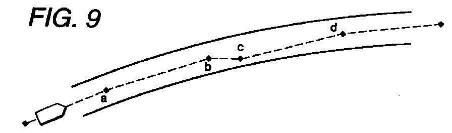
- the nodes stored in a CD-ROM of the navigation device 7 represent the shape of a road but does not necessarily trace the center line of the road precisely. Generally, as shown in Figures 9 to 15 at node b or c, they are plotted within the width of the road with some variations.
- a basic concept for setting singularities in this invention is that when the node interval between the adjacent nodes is less than a preset interval, one or both of the adjacent nodes are removed from the calculation of the curve's radius of curvature.
- the following operations should preferably be performed. That is, the node angles at the adjacent nodes are compared in absolute value and, when the absolute value of the large node angle is equal to or more than a predetermined threshold value or when the absolute value of the smaller node angle is equal to or less than a predetermined threshold value, the one or both of the nodes are removed from the calculation of the curve's radius of curvature.
- the following step may be taken.
- the angle formed by a line segment connecting the first two nodes and a line segment connecting the last two nodes is equal to or less than a predetermined threshold value and the line segments are almost parallel
- one or both of the intermediate two nodes may be removed from the calculation of the curve's radius of curvature.
- Figure 9 corresponds to this case.
- FIGS 4 to 7 show a singularity decision routine. Each node will be explained according to the reference number shown in Figures 9 to 15 and the decision on the singularity is performed for all nodes. In this routine, the node c is taken as a node to be checked for the singularity for the sake of convenience. The initial value of the singularity flag for each node is set to 0.
- step S1 compares a set node interval wk with a node interval Lp[c] between the node c to be checked for the singularity decision and the preceding node b.
- the set node interval wk as a threshold value to be compared with the node interval Lp[c] is the road width attribute wp[c] multiplied by a set node interval calculation coefficient wk1.
- a different set node interval calculation coefficient wk1 is set for each road kind attribute cp[j]. This is to make the singularity easier to set to prevent a sharp curve's radius of curvature from being calculated because the larger the road, the less frequent it will be to encounter a sharp curve.
- the routine moves to step S2 where a comparison is made between a minimum threshold angle tk1 and an angle (
- step S3 the routine moves to step S3 where it multiplies the node angles tp(b] and tp[c] and checks whether the multiplied result is positive or negative.
- it is positive value ( tp[b] ⁇ tp[c]>0 ) the nodes tp[b], tp[c] are bent in the same directions, so that the routine is exited.
- step S4 sets one or both of the singularity flags of the nodes b, c to 2 or 3 before being aborted.
- the singularity flag of at least one of the nodes b, c is set to 2 or 3 to remove the node from the calculation of the curve's radius of curvature.
- step S5 When it is decided at step S2 that
- Step S6 compares the absolute value of the node angle tp[b] of near-side node b with the absolute value of the node angle tp[c] of the node c, which is to be checked for singularity.
- the program moves to step S7.
- the program branches to step S18.
- the program compares the absolute value of the larger node angle tp[b] with the maximum threshold angle tk2.
- step S7 When at step S7 it is decided that
- step S8 the absolute value of the smaller node angle tp[c] and the minimum threshold angle tk1 are compared. Then, when
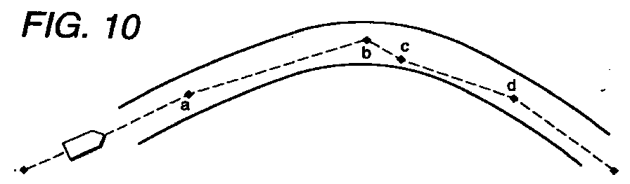
- This case corresponds to a node arrangement such as shown in Figure 10. That is, the node b which will likely trigger an alarm or deceleration control is followed closely by a node c on the curve, with a relatively large positional variation between the node b and the node c.
- the road is bent like a concave in a direction opposite the curve although the node c does not deviate out of the width of the actual road. This part constitutes a curve shape that cannot exist in reality.
- the node interval Lp[c] is very short, there is a possibility that calculating the curve's radius of curvature at the node b may result in a very small curve's radius of curvature far smaller than the actual curve geometry. Therefore, the singularity flag of the node c is set to 3 to remove the node c from the calculation of the curve's radius of curvature.
- step S10 the program removes the node c, which has its singularity set at 3, and then checks the singularity of the adjacent node d.
- step S10 the node c is eliminated and the node interval Lp[d], the node angles tp[b], tp[d] and others associated with the nodes b and d are calculated again.
- Steps S11-S13 check whether the node d is a singularity point or not. That is, step S11 compares the node interval Lp[d] and the set node interval wk, and step S12 multiplies the node angles tp[b] and tp[d] and checks whether the multiplied value is positive or negative. Then step S13 compares the absolute value of the node angle tp[b] with the minimum threshold angle tk1.
- the alarm and deceleration control based on the node d is too sensitive and makes the driver feel incongruous.
- the node interval will be too large, giving rise to a possibility that the calculated curve's radius of curvature may be close to a straight line, different from the actual curve geometry.
- the singularity flag of the node d is set to 1 to invalidate the calculated curve's radius of curvature and node angle, allowing the car to move on without initiating the alarm and deceleration control.
- step S5 of Figure 4 When the program branches from step S5 of Figure 4 to step S15 of Figure 5, it compares the absolute value of the node angle tp[b] of the near-side node b with the absolute value of the node angle tp[c] of the node c, which is to be checked for singularity.
- the program moves to step S16.
- the program branches to step S17.
- Step S16 compares the absolute value of the larger node angle tp[b] with the maximum threshold angle tk2.
- >tk2 the program proceeds to step S9 of Figure 4.
- the node c is close to the preceding node b, the road bending direction at the node b and the road bending direction at the node c are the same, and the node angle tp[c] at the node c is very small.
- the node c does not deviate from the actual road width, the road before and after the node c is close to a straight line, different from the actual curve geometry.
- the node interval Lp[c] is very short, there is a possibility that calculating the curve's radius of curvature at the node b may result in a very small curve's radius of curvature far smaller than the actual curve geometry.
- the singularity flag of the node c is set to 3 to eliminate the node from the calculation of the curve's radius of curvature.
- step S17 the program compares the absolute value of the larger node angle tp[c] with the maximum threshold angle tk2.
- ⁇ tk2 the program moves to step S20.
- step S17 the program checks whether the singularity flag of the node b is set to 3. If the singularity flag is found set to other than 3, the program moves to step S21 where it sets the singularity flag of the node b to 2 before exiting the routine. When the singularity flag of the node b is found set to 3, the program moves to step S22 where it sets the singularity flag of the node b to 4.
- the node b on a curve has a large positional variation with respect to the subsequent node c, which is to be checked for singularity, the road near the node b is locally bent like a concave in a direction opposite to the actual curve, resulting in a curve geometry that cannot exist in reality, although the node b is not deviated from the actual road width.
- the node interval Lp[c] is very short, there is a possibility that calculating the curve's radius of curvature at the node c may result in an extremely small curve's radius of curvature much smaller than the actual road curve geometry. Hence, the near-side node b is removed from the calculation of the curve's radius of curvature.
- step S6 of Figure 4 After branching from step S6 of Figure 4 to step S18 of Figure 5, the program compares the absolute value of the larger node angle tp[c] with the maximum threshold angle tk2. When
- Step S19 compares the absolute value of the smaller node angle tp[b] with the minimum threshold angle tk1.
- ⁇ tk1 the program moves to step S20 and, when
- Step S20 checks whether the singularity flag of the node b is set to 3. Depending on the check result, the singularity flag of the node b is set to either 2 or 4 at step S21 or step S22.
- step S23 and subsequent steps removes the node b whose singularity flag is set to 4 and then makes a singularity decision on the node c.
- step S24 compares the node interval Lp[c] and the set node interval wk; step S25 multiplies the node angles tp[a], tp(c] and checks whether the multiplied value is positive or negative; step S26 compares the absolute value of the node angle tp[a] with the maximum threshold angle tk2; and step S27 compares the absolute value of the node angle tp[c] with the maximum threshold angle tk2.
- the nodes a, b and c are located close to each other on a nearly straight road. Even when the node b preceding the node c is eliminated in the recalculation procedure, if the node interval Lp[c] which represents a distance between the nodes a and c is still small, the sequence of nodes z, a, c, d constitute an inappropriate local crank shape although the road is almost straight. Hence, the singularity of the node c is set to 1 to invalidate the calculated curve's radius of curvature and node angle and allows the car to move on without activating an alarm or deceleration control.
- the processing described above is successively executed for all nodes to check their singularity.
- the singularity information thus checked is output from the singularity decision unit 25h to the curve angle recalculation unit 25i and the curve's radius of curvature recalculation unit 25j.
- These recalculation units 25i, 25j calculate again the curve angle and the curve's radius of curvature for each node excluding the node which is determined as the singularity point based on the singularity information.
- the recalculation routine executed by these recalculation units 25i, 25j is performed according to the flow chart of Figure 8. This routine will be explained by taking, as an example node to be processed, the node e from among a series of nodes a, b, c, d, e, f consecutively arranged in the order of travel
- step S31 checks the value of the singularity flag of the node d preceding the node e, which is to be processed. When the value is 0, this means there is no anomaly with the node and thus the program exits the routine. When the value is other than 0, the program moves to step S32 where it checks the value of the singularity flag of the node c preceding the node d.
- step S33 the program branches to step S33 where it eliminates the node d and uses three nodes c, e, f to recalculate the node angle tp[e] and the curve's radius of curvature rp[e] of the node e before exiting the routine.
- step S34 checks the singularity flag of the node e, which is to be processed. When it is 0, which means there is no anomaly, the program branches to step S35. When the singularity flag is set with other than 0, the program moves to step S36.
- step S35 the program removes the nodes c and d and uses the nodes b, e, f to recalculate the node angle tp[e] and the curve's radius of curvature rp[e] of the node e before existing the routine.
- step S38 After moving from step S36 or S37 to step S38, the program sets the singularity flag of the node c to 1 before exiting the routine.
- the node angle is calculated for a node immediately following the node judged as a singularity point (a node to be removed from the curve's radius of curvature calculation) by the singularity decision unit 25h and the curve's radius of curvature is calculated for a node immediately preceding the node judged as the singularity point.
- the nodes c, e, f are used to calculate the curve angle and the curve's radius of curvature (step S33). If the node c too is judged as the singularity point (a node to be removed from the curve's radius of curvature calculation), the curve angle and the curve's radius of curvature at the node e are recalculated by using the node b, e, f (step S35).
- the node e too is judged as the singularity point (a node to be removed from the curve's radius of curvature calculation)
- the node e is judged to be a node for which the curve's radius of curvature cannot be calculated (the singularity flag is set to 1), with the result that the node e itself is removed from the alarm and deceleration control and no recalculation is performed (step S38).
- the nodes b, e, f are used to calculate the curve angle and the curve's radius of curvature (step S35).
- the expressway and general road with a large width normally do not have a sharp or complicated curve and thus there is no need to calculate a curve's radius of curvature which is smaller than the actual road geometry.
- a narrow general road there can be complex and sharp curves depending on locations and it is therefore considered safer to calculate a curve's radius of curvature so that it can be used for the possible alarm and deceleration control even if it is somewhat smaller than the actual road geometry.
- the node angle and the curve's radius of curvature calculated by the curve angle recalculation unit 25i and the curve's radius of curvature recalculation unit 25j are output to an allowable lateral acceleration setting unit 26 and an allowable approach speed setting unit 27.
- the allowable lateral acceleration setting unit 26 calculates a reference value ayl1 of the allowable lateral acceleration ayl according to the road surface friction coefficient ⁇ , corrects the reference value ayl1 by the road gradient SL, sets an allowable lateral acceleration ayl2, corrects the allowable lateral acceleration ayl2 according to the curve approach limit speed ((ayl1/rp[j])1/2), and sets a final allowable lateral acceleration ayl.
- the allowable lateral acceleration ayl is read into the allowable approach speed setting unit 27.
- the allowable approach speed setting unit 27 first calculates a reference value vap0 of the allowable approach speed for the node Pj from the following equation based on the allowable lateral acceleration ayl and the curve's radius of curvature rp[j] stored in the front road attribute calculation/storage unit 25.
- vap0 (ayl ⁇
- vap1 vap0 ⁇ Kt
- Kt is a curve depth correction coefficient determined by the curve depth tpa and is so set that it decreases as the curve depth tpa increases. This is intended to make corrections so as to reduce the allowable approach speed at the curve as the curve depth tpa increases because at a large curve depth tpa the cornering becomes difficult.
- the allowable approach speed vap1 is further corrected to determine an allowable approach speed vap2 in order to prevent the allowable approach speed from becoming extremely small.
- the allowable approach speeds vap2 of the nodes making up the same curve are smoothed out to adjust their variations and thereby set a final allowable approach speed vap.
- a comparison is made among the following three approach speed: the allowable approach speed vap2[j] at the node Pj, which is one of the nodes making up the same curve; an average value of the vap2[j] and an allowable approach speed vap2[j+1] at the next node Pj+1; and an average value of the allowable approach speed vap2[j] and an allowable approach speed vap2[j-1] at the preceding node Pj-1.
- a median value of the three is set as a final allowable approach speed vap for the node Pj.
- the smoothing processing for a node adjacent to the node for which the singularity flag is set is performed by using not the allowable approach speed of the singularity point node but the allowable approach speed of the adjacent node. For the node with the singularity flag set to 1, the allowable approach speed is not set, thus assuring that the alarm and deceleration control for the node cannot be executed.
- An alarm speed calculation/storage unit 28 determines an alarm speed vw[j] at the present car position according to the allowable approach speed vap[j] at each node set by the allowable approach speed setting unit 27, the node interval Lp[j] at each node stored in the front road attribute calculation/storage unit 25, and the allowable deceleration XgLim set by the allowable deceleration setting unit 24.
- LL[j] LL[1] + Lp[2] + Lp[3] + ... + Lp[j] when 2 ⁇ j ⁇ n-1
- the alarm speed vw[j] for each node can therefore be set by the following equation.
- vw[j] (vap[j]2 + 2 ⁇ (Kx ⁇ XgLim) ⁇ LL[j])1/2 where Kx is a safety coefficient which is 0.5 in this embodiment. In other words, 50% of the allowable deceleration XgLim is taken as the safe deceleration.
- An alarm decision output unit 29 compares the minimum of the alarm speeds vw[j] for the nodes determined by the alarm speed calculation/storage unit 28 with the car speed v calculated based on the output signal from the car speed sensor 5. It also compares the car speed v with the allowable approach speed vap[j] of the node having the minimum alarm speed vw[j].
- the alarm decision output unit 29 decides that the car is running in an overspeed state.
- a deceleration decision output unit 30 decides that the node should be subjected to the deceleration control.
- a brake pressure is detected from the output signal from the brake pressure sensor 9 and, based on the brake pressure, a check is made of whether the braking operation on the part of the driver has achieved the deceleration set by the allowable deceleration setting unit 24. If the set deceleration is not realized, the node is judged as an object for the deceleration control.
- a control execution decision unit 31 checks whether or not to permit the actual control to be performed on the node that was judged by the alarm decision output unit 29 as an object for the alarm control or on the node that was judged by the deceleration decision output unit 30 as an object for the deceleration control.
- the control execution decision unit 31 checks whether the node of interest actually exists on the road as by reading the curve's radius of curvature rp at the node from the road attribute stored in the front road attribute calculation/storage unit 25, reading the distance LL to the node stored in the alarm speed calculation/storage unit 28, and checking the curve's radius of curvature rp and the distance LL against the degree of curvature of the road in front and the distance to the curve start point, both recognized by the road shape detection device 10. When they agree, the control execution decision unit 31 decides that the node of interest actually exists on the road and permits the execution of the alarm or deceleration control.
- the control execution decision unit 31 prohibits the execution of the alarm and deceleration control for that node.
- the alarm decision output unit 29 When the control execution decision unit 31 permits the execution of the alarm control or the deceleration control for the node under consideration, the alarm decision output unit 29 outputs an alarm command signal to the alarm device 11 to inform and alert the driver that the car is on the verge of entering a curve.
- the deceleration decision output unit 30 outputs a deceleration command signal to the deceleration device 12, which, based on the deceleration command from the deceleration decision output unit 30, performs a forced deceleration operation as by shifting down the transmission, reducing the engine torque and braking.
- this embodiment removes from the calculation of the curve's radius of curvature an inappropriate node which has, for example, an extremely short node interval. This makes it possible to calculate an appropriate curve's radius of curvature that matches the actual road curve and, based on the calculated curve's radius of curvature, set an allowable curve approach speed that will not make the driver feel incongruous.
- the present invention calculates, based on the node data output from the navigation device, a node interval between each node and an adjacent node and a node angle for each node; detects, based on the node interval and the node angle, a node which should be removed from the calculation of the curve's radius of curvature; and calculates the curve's radius of curvature by removing this node.
- the node interval is very short, it is possible to calculate the curve's radius of curvature that approximates the actual curve and, based on this calculated curve's radius of curvature, set an appropriate allowable curve approach speed.
- overly sensitive alarm and deceleration controls can be avoided, alleviating the sense of incongruity the driver may have.
Abstract
Description
- The present invention relates to a road shape estimation apparatus to eliminate improper nodes for calculating a radius of curvature for a curve and to a curve approach speed control apparatus using the road shape estimation apparatus.
- JP-A-4-236699 proposes a vehicle traveling system which calculates an allowable approach speed for a curve in front by using data (node data) on points on the ground (nodes) shown on a road map of a navigation device, detects a speed higher than the allowable approach speed, i.e., an overspeed state for the curve in front, and issues an alarm or performs a speed reduction control.
- The applicant of this invention has proposed in JP-A-11-2528 a method for determining a radius of curvature for a curve based on a plurality of node data output from the navigation device.
- That is, for three consecutive nodes, the center node and the two other nodes on both sides are connected with straight lines, and the lengths of the two straight lines are compared. A half the length of the shorter straight line is taken from the center node on both straight lines to find mid points. At the mid points normal lines perpendicular to their own straight lines are drawn until they intersect each other. The distance from the point of intersection to each mid point is set as a radius of curvature for a curve.
- A method in JP-A-11-83501 calculates, based on a radius of curvature for a curve and a lateral acceleration, an allowable curve approach speed at which the vehicle can safely negotiate the curve in front, compares the allowable curve approach speed with the car speed in a predetermined procedure to check whether the curve can be safely negotiated, and, if the decision indicates an overspeed, issues an alarm prompting the user to decrease the speed or forcibly performs a speed reduction control as required.
- When calculating the curve's radius of curvature based on the distances between the three consecutive nodes, if the node distances are extremely short, the curve's radius of curvature based on half the node distance is likely to be calculated far smaller than the actual curve's radius of curvature. As a result, if the allowable curve approach speed is calculated based on the erroneously calculated curve's radius of curvature, it will be set to an extremely slow speed, giving rise to a problem that even when the car is actually traveling at a speed at which it can safely negotiate the curve, an alarm may be issued or the speed reduction control activated, making the driver feel incongruous.
- The present invention has been accomplished under these circumstances to provide a road shape estimation apparatus and a curve approach speed control apparatus using the road shape estimation apparatus, which, even when the node intervals are extremely short, can calculate a curve's radius of curvature approximating the actual curve, set an appropriate allowable curve approach speed and thereby alleviate a sense of incongruity from the driver.
- To achieve the above objective, a first road shape estimation apparatus according to the present invention comprises inputting a plurality of node data concerning a road in front from a navigation device, calculating, based on the node data, a node interval between each node and an adjacent node and a node angle for each node, and, based on the node intervals and the node angles, calculating a curve's radius of curvature for each node, wherein the road shape estimation apparatus detects, based on the node intervals and the node angles, a node which constitutes a curve's radius of curvature calculation removal point, and calculates the curve's radius of curvature by removing the node which constitutes the curve's radius of curvature calculation removal point.
- In this configuration, when inputting a plurality of node data concerning a road in front from a navigation device, calculating, based on the node data, a node interval between each node and an adjacent node and a node angle for each node, and, based on the node intervals and the node angles, calculating a curve's radius of curvature for each node, the apparatus detects, based on the node intervals and the node angles, a node which constitutes a curve's radius of curvature calculation removal point, and calculates the curve's radius of curvature by removing the node which constitutes the curve's radius of curvature calculation removal point.
- A second road shape estimation apparatus is characterized in that, in the first road shape estimation apparatus, when the node interval is equal to or less than a preset node interval, at least one of nodes at both ends of the node interval is taken as the curve's radius of curvature calculation removal point.
- With this configuration, when the node interval is equal to or less than a preset node interval, at least one of nodes at both ends of the node interval is taken as the curve's radius of curvature calculation removal point.
- A third road shape estimation apparatus is characterized in that, in the first road shape estimation apparatus, when the node interval is equal to or less than a preset node interval and bending directions of the node angles calculated at the two nodes situated at the both ends of the node interval are opposite, at least one of the two nodes is taken as the curve's radius of curvature calculation removal point.
- With this configuration, when the node interval is equal to or less than a preset node interval and bending directions of the node angles calculated at the two nodes situated at the both ends of the node interval are opposite, at least one of the two nodes is taken as the curve's radius of curvature calculation removal point.
- A fourth road shape estimation apparatus is characterized in that, in the first road shape estimation apparatus, when the node interval is equal to or less than a preset node interval and a larger one of the node angles calculated at the two nodes situated at the both ends of the node interval is equal to or more than a preset maximum threshold angle, at least one of the two nodes is taken as the curve's radius of curvature calculation removal point.
- With this configuration, when the node interval is equal to or less than a preset node interval and a larger one of the node angles calculated at the two nodes situated at the both ends of the node interval is equal to or more than a preset maximum threshold angle, at least one of the two nodes is taken as the curve's radius of curvature calculation removal point.
- A fifth road shape estimation apparatus is characterized in that, in the first road shape estimation apparatus, when the node interval is equal to or less than a preset node interval and a smaller one of the node angles calculated at the two nodes situated at the both ends of the node interval is equal to or less than a preset minimum threshold angle, at least one of the two nodes is taken as the curve's radius of curvature calculation removal point.
- With this configuration, when the node interval is equal to or less than a preset node interval and a smaller one of the node angles calculated at the two nodes situated at the both ends of the node interval is equal to or less than a preset minimum threshold angle, at least one of the two nodes is taken as the curve's radius of curvature calculation removal point.
- A sixth road shape estimation apparatus is characterized in that, in the first road shape estimation apparatus, when an angle formed by a line connecting first two of four consecutive nodes and a line connecting last two nodes is equal to or less than a preset minimum threshold angle and a node interval connecting two middle nodes is equal to or less than a preset node interval, at least one of the two middle nodes is taken as the curve's radius of curvature calculation removal point.
- With this configuration, when an angle formed by a line connecting first two of four consecutive nodes and a line connecting last two nodes is equal to or less than a preset minimum threshold angle and a node interval connecting two middle nodes is equal to or less than a preset node interval, at least one of the two middle nodes is taken as the curve's radius of curvature calculation removal point.
- A seventh road shape estimation apparatus is characterized in that, in the second road shape estimation apparatus, the preset node interval is set by multiplying a preset node interval calculation coefficient by a road width coefficient.
- With this configuration, the preset node interval is set by multiplying a preset node interval calculation coefficient by a road width coefficient.
- A eighth road shape estimation apparatus is characterized in that, in the seventh road shape estimation apparatus, the preset node interval calculation coefficient is set for each road kind.
- With this configuration, the preset node interval calculation coefficient is set for each road kind.
- A ninth road shape estimation apparatus is characterized in that, in the fourth road shape estimation apparatus, the maximum threshold angle or the minimum threshold angle is set by multiplying a preset reference angle by a ratio between the node interval and the preset node interval.
- With this configuration, the maximum threshold angle or the minimum threshold angle is set by multiplying a preset reference angle by a ratio between the node interval and the preset node interval.
- A first curve approach control apparatus using any one of the first to ninth road shape estimation apparatus is characterized in that when a node interval between two nodes adjacent to, and on both sides of, the node which is taken as the curve's radius of curvature calculation removal point is equal to or less than a preset node interval, an alarm or deceleration control for at least one of the two nodes is prohibited.
- With this configuration, when a node interval between two nodes adjacent to, and on both sides of, the node which is taken as the curve's radius of curvature calculation removal point is equal to or less than a preset node interval, an alarm or deceleration control for at least one of the two nodes is prohibited.
- A second curve approach control apparatus using any one of the first to ninth road shape estimation apparatus is characterized in that when a curve angle of at least one of two nodes adjacent to, and on both sides of, the node which is taken as the curve's radius of curvature calculation removal point is equal to or less than the preset minimum threshold angle, an alarm or deceleration control for the at least one node is prohibited.
- With this configuration, when a curve angle of at least one of two nodes adjacent to, and on both sides of, the node which is taken as the curve's radius of curvature calculation removal point is equal to or less than the preset minimum threshold angle, an alarm or deceleration control for the at least one node is prohibited.
- By way of example only, a specific embodiment of the present invention will now be described, with reference to the accompanying drawings, in which:
- Figure 1 is a functional block diagram of the control unit installed in the curve approach control apparatus;
- Figure 2 is a function block diagram of the front road attribute calculation/storage unit;
- Figure 3 is an explanatory diagram of information output from the navigation device;
- Figure 4 is a flow chart showing a singularity point decision routine;
- Figure 5 is a flow chart showing a singularity point decision routine (continued);
- Figure 6 is a flow chart showing a singularity point decision routine (continued);
- Figure 7 is a flow chart showing a singularity point decision routine (continued);
- Figure 8 is a flow chart showing a recalculation routine;
- Figure 9 is an explanatory diagram showing a singularity point among nodes on an almost straight road;
- Figure 10 is an explanatory diagram showing an example in which a singularity node exists on a curve;
- Figure 11 is an explanatory diagram showing another example in which a singularity node exists on a curve;
- Figure 12 is an explanatory diagram showing a further example in which a singularity node exists on a curve;
- Figure 13 is an explanatory diagram showing a further example in which a singularity node exists on a curve;
- Figure 14 is an explanatory diagram showing a further example in which a singularity node exists on a curve;
- Figure 15 is an explanatory diagram showing a further example in which a singularity node exists on a curve;
- Figure 16 is an explanatory diagram showing node coordinates with a car position as a reference;
- Figure 17 is an explanatory diagram showing a method of calculating a curve's radius of curvature; and
- Figure 18 is a characteristic diagram showing the relation between a car speed and an alarm speed.
-
- One embodiment of the present invention will be described by referring to the accompanying drawings. Figure 1 shows a functional block diagram of a control unit installed in the curve approach control apparatus.
- A
control unit 1 of the curve approach control apparatus receives at its input side various data including a yaw rate τ detected by ayaw rate sensor 2, a rudder angle δf detected by a steeringwheel angle sensor 3, a lateral acceleration Gy detected by a lateral acceleration sensor 4, a car speed V detected by acar speed sensor 5, a longitudinal acceleration detected by alongitudinal acceleration sensor 6, and a brake pressure detected by abrake pressure sensor 9. Thecontrol unit 1 also receives signals from anavigation device 7 and a roadshape detection device 10. - As shown in Figure 3, the
navigation device 7 periodically (every 500 ms, for example) issues information including a node number n along a car travel route, an east longitude of car position and a north latitude of car position, data on the node directly after the car, data on the node directly before the car, data on the second node in front of the car, data on the (n-1)th node in front of the car. - The road
shape detection device 10 detects the state of a curve (direction of curve, radius of curvature, etc.) of the road in front by using a CCD camera and outputs the information to thecontrol unit 1. - Based on the information detected by the sensors 2-6, 9, the
navigation device 7 and the roadshape detection device 10, thecontrol unit 1 performs calculation to check whether the car can negotiate the curve in front stably when it enters the curve at the present speed, and drives analarm device 11 such as a buzzer, a voice alarm or an alarm lamp to alert the operator, if necessary. - When the speed must be lowered forcibly, a deceleration command is issued to a
deceleration device 12. Thedeceleration device 12, according to the deceleration command from thecontrol unit 1, performs a deceleration control such as downshifting of the transmission, lowering the engine torque and applying brake. - In the
control unit 1 shown in Figure 1, a road surface frictioncoefficient estimation unit 21 estimates a road surface friction coefficient µ based on parameters representing the behavior of the car, such as yaw rate τ, rudder angle δf, lateral acceleration Gy and car speed V, by using a calculation method disclosed in JP-A8-2274 already filed by the applicant of this invention. A roadgradient estimation unit 22 estimates a road gradient SL according to the rate of change of the car speed V calculated in a car speedchange calculation unit 23 every set duration of time and the longitudinal acceleration. - Based on the road condition determined from the road surface friction coefficient µ and the road gradient SL, an allowable
deceleration setting unit 24 sets an allowable deceleration XgLim for the car. The method of estimating the road gradient SL and the method of calculating the allowable deceleration XgLim are described in JP-A-11-83501 already filed by the applicant of this invention and therefore their explanations are omitted here. - A front road attribute calculation/
storage unit 25 reads information (see Figure 3) for each node output from thenavigation device 7, calculates, based on these information, an interval between the current node and the node directly in front Lp[j] for each node, a curve's radius of curvature rp[j] and others, and stores the calculated data as node attributes in a storage means such as RAM. The intersection attribute ip[j], road width attribute wp[j] and others are also stored as node attributes in the storage means. - In more concrete terms, as shown in Figure 2, the front road attribute calculation/
storage unit 25 has a node coordinatestorage unit 25a, a road kindinformation storage unit 25b, a road widthinformation storage unit 25c, an intersection information storage unit 25d, a nodeinterval calculation unit 25e, a curveangle calculation unit 25f, a curve's radius of curvature calculation unit 25g, asingularity decision unit 25h, a curveangle recalculation unit 25i, and a curve's radius ofcurvature recalculation unit 25j. - The
storage units 25a-25d store road information, with its own car position as a reference, which is output from thenavigation device 7 while running. That is, the node coordinatestorage unit 25a stores a coordinate Pj representing the position of each node, and the road kindinformation storage unit 25b stores a road kind attribute cp[j] of each node. The road kind attribute cp[j] refers to a kind of road, such as highway or ordinary road, and is set as shown in a table below.Expressway 5 City expressway 4 General highway 3 Main local road 2 Other road 1 - The road width
information storage unit 25c, according to the road width flag issued from thenavigation device 7, sets the road width attributes wp[j] of the roads that the car is going to travel, and stores the attributes. The road width attribute wp[j] for each node is, for example, set as shown in a table below to represent the actual road width of the flag output from thenavigation device 7.Road width range indicated by flag Road width attribute 3 m or less 3 m 3-5.5 m 5 m 5.5-13 m 10 m 13 m or more 15m - The intersection information storage unit 25d uses the intersection flag information output from the
navigation device 7 to set and store the intersection attribute ip[j]. The intersection flag information is set as shown in a table below.Other than intersection 0 Intersection 1 Intersection on guided path 2 - The intersection on a guided path refers to an intersection on a guided path used when a destination is set in the
navigation device 7. - The node
interval calculation unit 25e calculates an interval (node interval) Lp[j] between the node coordinate Pj stored in the node coordinatestorage unit 25a and a node Pj-1 immediately preceding it. That is, as shown in Figure 16, the nodeinterval calculation unit 25e calculates a node interval Lp[j] between the node Pj and the adjacent node Pj-1 from the following formula based on the node coordinates P0 (xp[0], yp[0]), P1 (xp[1], yp[1]), ... Pj-1 (xp[j-1], yp[j-1]), Pj (xp[j], yp[j]), ... Pn-1 (xp[n-1], yp[n-1]). - The curve
angle calculation unit 25f calculates a node angle tp[j] at the node Pj (see Figure 17) from the following formula. - The node angle tp[j] obtained here is represented as a positive value for the right curve and a negative value for the left curve.
- The curve's radius of curvature calculation unit 25g calculates a curve's radius of curvature rp[j] at the node Pj from the following formula based on the node interval Lp[j], Lp[j+1] and the node angle tp[j].
- The
singularity decision unit 25h sets whether each node is a singularity point. The singularity point is represented by a flag value of 0-4 and is defined as follows. - This value indicates that there is no anomaly. The initial value of the singularity point flag of all nodes is 0.
- This value disables alarm and deceleration control for the associated node.
- This value is set for a near side node of two adjacent nodes with a short node interval and is removed when calculating the curve's radius of curvature.
- This value is set for a far side node of two adjacent nodes with a short node interval and is removed when calculating the curve's radius of curvature.
- This value is set for a node which is identified as both the
singularity point 2 and thesingularity point 3 and is removed when calculating the curve's radius of curvature. - Therefore, when the singularity point is other than 0, the node is removed when calculating the curve's radius of curvature.
- The nodes stored in a CD-ROM of the
navigation device 7 represent the shape of a road but does not necessarily trace the center line of the road precisely. Generally, as shown in Figures 9 to 15 at node b or c, they are plotted within the width of the road with some variations. - When the adjacent nodes are abnormally close and if the curve's radius of curvature is calculated based on this narrow node interval, the calculated radius of curvature will be too small compared with the actual road curve's radius of curvature, with the result that an alarm or deceleration control may be activated too sensitively when in reality the curve has a moderate curvature. Hence, when the curve's radius of curvature is calculated, such nodes are removed from the calculation as singularities or the result of calculation is rendered invalid thereby preventing too sensitive an alarm or deceleration from being activated.
- A basic concept for setting singularities in this invention is that when the node interval between the adjacent nodes is less than a preset interval, one or both of the adjacent nodes are removed from the calculation of the curve's radius of curvature.
- In addition to this basic concept, the following operations should preferably be performed. That is, the node angles at the adjacent nodes are compared in absolute value and, when the absolute value of the large node angle is equal to or more than a predetermined threshold value or when the absolute value of the smaller node angle is equal to or less than a predetermined threshold value, the one or both of the nodes are removed from the calculation of the curve's radius of curvature.
- Further, in addition to the basic concept of the present invention, when the bending directions of the node angles at the adjacent nodes are opposite, it is preferred that one or both of the nodes be removed from the calculation of the curve's radius of curvature. It is further preferred that when the absolute value of the larger one of the node angles at the adjacent nodes is larger than a predetermined threshold value or when the absolute value of the smaller node angle is smaller than a predetermined threshold value, one or both of the nodes be removed from the calculation of the curve's radius of curvature. Figures 10 and 12 correspond to these cases.
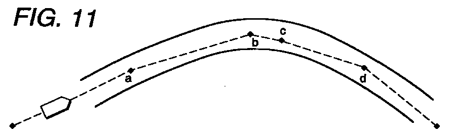
- In addition to the above basic concept of the present invention, it possible to remove one or both of the nodes from the calculation of the curve's radius of curvature when the bending directions of the node angles at the adjacent nodes are the same. In that case, when the absolute value of the larger one of the node angles at the adjacent nodes is larger than a predetermined threshold value, it is further preferred that one or both of the nodes be removed from the calculation of the curve's radius of curvature. Figures 11 and 13 correspond to these cases.
- In addition to the above basic concept of the present invention, the following step may be taken. In the four consecutive nodes, when the angle formed by a line segment connecting the first two nodes and a line segment connecting the last two nodes is equal to or less than a predetermined threshold value and the line segments are almost parallel, one or both of the intermediate two nodes may be removed from the calculation of the curve's radius of curvature. Figure 9 corresponds to this case.
- One example of the setting of a singularity flag for each node as executed by the
singularity decision unit 25h will be explained by referring to the flow chart shown in Figure 4 to Figure 8. - Figures 4 to 7 show a singularity decision routine. Each node will be explained according to the reference number shown in Figures 9 to 15 and the decision on the singularity is performed for all nodes. In this routine, the node c is taken as a node to be checked for the singularity for the sake of convenience. The initial value of the singularity flag for each node is set to 0.
- In the flow charts shown in Figures 4 to 7, step S1 compares a set node interval wk with a node interval Lp[c] between the node c to be checked for the singularity decision and the preceding node b.
- The set node interval wk as a threshold value to be compared with the node interval Lp[c] is the road width attribute wp[c] multiplied by a set node interval calculation coefficient wk1. A different set node interval calculation coefficient wk1 is set for each road kind attribute cp[j]. This is to make the singularity easier to set to prevent a sharp curve's radius of curvature from being calculated because the larger the road, the less frequent it will be to encounter a sharp curve.
- When Lp[c]≥wk, the node interval Lp[c] is longer than the set node interval wk, so that the routine is exited. When Lp[c]<wk, i.e., the interval is short, the routine moves to step S2 where a comparison is made between a minimum threshold angle tk1 and an angle (|tp(b]+tp[c]|) formed by a line connecting the nodes a and b (vector ab) and a line connecting the nodes c and d (vector cd).
- The minimum threshold angle tk1 for the angle between the vector ab and the vector cd is obtained by multiplying a reference angle tk0 (for example 6°) by a ratio of the set node interval wk to the node interval Lp[c] of the node c, which is to be checked for singularity (
- When
- That is, when nodes a, b, c, d are arranged in a crank shape and the directions of the vector ab and the vector cd are almost equal, there is a possibility that calculating the curve's radius of curvature for the node b or c may result in an extremely small curve's radius of curvature much smaller than the actual geometry of the curve. Hence, the singularity flag of at least one of the nodes b, c is set to 2 or 3 to remove the node from the calculation of the curve's radius of curvature.
- When it is decided at step S2 that
- Step S6 compares the absolute value of the node angle tp[b] of near-side node b with the absolute value of the node angle tp[c] of the node c, which is to be checked for singularity. When the absolute value of the node angle tp[b] is larger than the absolute value of the node angle tp[c] (|tp(b]|>|tp[c]|), the program moves to step S7. When the absolute value of the near-side node angle tp[b] is smaller than the absolute value of the node angle tp[c] (|tp[b]|≤|tp[c]|), the program branches to step S18.
- At step S7, the program compares the absolute value of the larger node angle tp[b] with the maximum threshold angle tk2. The maximum threshold angle tk2 is determined by. multiplying the reference angle tk0 (e.g., 6°) by a ratio of the node interval Lp[c] of the node c, which is to be checked for singularity, to the set node interval wk (
- This is intended to make it more likely that the small node interval Lp[c] will be identified as a singularity point because the smaller the node interval Lp[c], the more likely the calculated value of curve's radius of curvature rp[c] will be set to an abnormally small value.
- When at step S7 it is decided that |tp[b]|≥tk2, the program moves to step S8. When |tp[b]|<tk2, the routine is exited. At step S8, the absolute value of the smaller node angle tp[c] and the minimum threshold angle tk1 are compared. Then, when |tp[c]|≤tk1, the routine moves to step S9, where it sets the singularity flag of the node c, which is to be checked for singularity, to 3 before moving to step 10. When |tp[c]|>tk1, the routine is aborted.
- This case corresponds to a node arrangement such as shown in Figure 10. That is, the node b which will likely trigger an alarm or deceleration control is followed closely by a node c on the curve, with a relatively large positional variation between the node b and the node c. At around the node c, the road is bent like a concave in a direction opposite the curve although the node c does not deviate out of the width of the actual road. This part constitutes a curve shape that cannot exist in reality. Further, because the node interval Lp[c] is very short, there is a possibility that calculating the curve's radius of curvature at the node b may result in a very small curve's radius of curvature far smaller than the actual curve geometry. Therefore, the singularity flag of the node c is set to 3 to remove the node c from the calculation of the curve's radius of curvature.
- Then the program moves to step S10. At steps S10 and subsequent steps the program removes the node c, which has its singularity set at 3, and then checks the singularity of the adjacent node d.
- First, at step S10 the node c is eliminated and the node interval Lp[d], the node angles tp[b], tp[d] and others associated with the nodes b and d are calculated again.
- Steps S11-S13 check whether the node d is a singularity point or not. That is, step S11 compares the node interval Lp[d] and the set node interval wk, and step S12 multiplies the node angles tp[b] and tp[d] and checks whether the multiplied value is positive or negative. Then step S13 compares the absolute value of the node angle tp[b] with the minimum threshold angle tk1.
- When Lp[d]<wk,
- When Lp[d]≥wk,
- That is, as shown in Figure 14, when the node c is identified as a removal point for the curve's radius of curvature calculation because the singularity flag of the node c is set to 3, the node c is removed and the curve's radius of curvature rp[d] and the node angle tp[d] at the node d are calculated based on information stored in the nodes b, d, e. If the node interval Lp[d] at the node d is short and the road before and after the node b is almost linear, different from the actual curve shape, the calculated curve's radius of curvature at the node d cannot be said to represent the actual curve geometry and is highly likely to assume a significantly small value. This possibility is particularly high with expressways and general roads with a large width.
- In such a case, the alarm and deceleration control based on the node d is too sensitive and makes the driver feel incongruous. When the recalculation is made by eliminating the node d, the node interval will be too large, giving rise to a possibility that the calculated curve's radius of curvature may be close to a straight line, different from the actual curve geometry. Hence, the singularity flag of the node d is set to 1 to invalidate the calculated curve's radius of curvature and node angle, allowing the car to move on without initiating the alarm and deceleration control.
- When the program branches from step S5 of Figure 4 to step S15 of Figure 5, it compares the absolute value of the node angle tp[b] of the near-side node b with the absolute value of the node angle tp[c] of the node c, which is to be checked for singularity. When the absolute value of the near-side node angle tp[b] is larger than the absolute value of the node angle tp(c] (|tp[b]|>|tp[c]|), the program moves to step S16. When the absolute value of the near-side node angle tp[b] is smaller than the absolute value of the node angle tp[c] (|tp[b]|≤|tp[c]|), the program branches to step S17.
- Step S16 compares the absolute value of the larger node angle tp[b] with the maximum threshold angle tk2. When |tp[b]|>tk2, the program proceeds to step S9 of Figure 4. When |tp(b]|≤tk2, the routine is exited.
- In Figure 11, the node c is close to the preceding node b, the road bending direction at the node b and the road bending direction at the node c are the same, and the node angle tp[c] at the node c is very small. Although the node c does not deviate from the actual road width, the road before and after the node c is close to a straight line, different from the actual curve geometry. Further, because the node interval Lp[c] is very short, there is a possibility that calculating the curve's radius of curvature at the node b may result in a very small curve's radius of curvature far smaller than the actual curve geometry. Because the node angle tp[c] at the node c is small and the node c is not necessary in representing the curve geometry, the singularity flag of the node c is set to 3 to eliminate the node from the calculation of the curve's radius of curvature.
- After branching from step S15 to step S17, the program compares the absolute value of the larger node angle tp[c] with the maximum threshold angle tk2. When |tp[c]|≥tk2, the program moves to step S20. When |tp[c]|<tk2, the program exits the routine.
- After moving from step S17 to step S20, the program checks whether the singularity flag of the node b is set to 3. If the singularity flag is found set to other than 3, the program moves to step S21 where it sets the singularity flag of the node b to 2 before exiting the routine. When the singularity flag of the node b is found set to 3, the program moves to step S22 where it sets the singularity flag of the node b to 4.
- That is, when, as shown in Figure 12, the node b on a curve has a large positional variation with respect to the subsequent node c, which is to be checked for singularity, the road near the node b is locally bent like a concave in a direction opposite to the actual curve, resulting in a curve geometry that cannot exist in reality, although the node b is not deviated from the actual road width. Because the node interval Lp[c] is very short, there is a possibility that calculating the curve's radius of curvature at the node c may result in an extremely small curve's radius of curvature much smaller than the actual road curve geometry. Hence, the near-side node b is removed from the calculation of the curve's radius of curvature.
- After branching from step S6 of Figure 4 to step S18 of Figure 5, the program compares the absolute value of the larger node angle tp[c] with the maximum threshold angle tk2. When |tp[c]|≥tk2, the program moves to step S19 and, when |tp[c]|<tk2, exits the routine.
- Step S19 compares the absolute value of the smaller node angle tp[b] with the minimum threshold angle tk1. When |tp[b]|≤tk1, the program moves to step S20 and, when |tp[b]|>tk1, exits the routine.
- Step S20 checks whether the singularity flag of the node b is set to 3. Depending on the check result, the singularity flag of the node b is set to either 2 or 4 at step S21 or step S22.
- That is, as shown in Figure 13, when the near-side node b is located very close to the next node c, which is to be checked for singularity, and the node angle tp[b] of the node b is very small, the road before and after the node b is linear, different from the actual curve geometry although the node b is not deviated from the actual road width. Because the node b and node c are very close to each other, calculating the curve's radius of curvature at the node c may result in a curve's radius of curvature much smaller than the actual road curve geometry. Hence, because the node angle at the node b is small and thus the node b is not necessary in representing the curve geometry, the node b is eliminated from the calculation of the curve's radius of curvature.
- Further, after proceeding from step S22 to step S23 of Figure 7, the program at step S23 and subsequent steps removes the node b whose singularity flag is set to 4 and then makes a singularity decision on the node c.
- That is, step S24 compares the node interval Lp[c] and the set node interval wk; step S25 multiplies the node angles tp[a], tp(c] and checks whether the multiplied value is positive or negative; step S26 compares the absolute value of the node angle tp[a] with the maximum threshold angle tk2; and step S27 compares the absolute value of the node angle tp[c] with the maximum threshold angle tk2.
- Then, when Lp[c]<wk,
- When Lp[d]≥wk,
- That is, in this case, as shown in Figure 15, the nodes a, b and c are located close to each other on a nearly straight road. Even when the node b preceding the node c is eliminated in the recalculation procedure, if the node interval Lp[c] which represents a distance between the nodes a and c is still small, the sequence of nodes z, a, c, d constitute an inappropriate local crank shape although the road is almost straight. Hence, the singularity of the node c is set to 1 to invalidate the calculated curve's radius of curvature and node angle and allows the car to move on without activating an alarm or deceleration control.
- The processing described above is successively executed for all nodes to check their singularity. When the processing has been completed for all nodes, the singularity information thus checked is output from the
singularity decision unit 25h to the curveangle recalculation unit 25i and the curve's radius ofcurvature recalculation unit 25j. Theserecalculation units - The recalculation routine executed by these
recalculation units - First, step S31 checks the value of the singularity flag of the node d preceding the node e, which is to be processed. When the value is 0, this means there is no anomaly with the node and thus the program exits the routine. When the value is other than 0, the program moves to step S32 where it checks the value of the singularity flag of the node c preceding the node d.
- Then, when the singularity flag of the node c is 0, the program branches to step S33 where it eliminates the node d and uses three nodes c, e, f to recalculate the node angle tp[e] and the curve's radius of curvature rp[e] of the node e before exiting the routine.
- When at step S32 the singularity flag of the node c is found to be other than 0, the next step S34 checks the singularity flag of the node e, which is to be processed. When it is 0, which means there is no anomaly, the program branches to step S35. When the singularity flag is set with other than 0, the program moves to step S36.
- At step S35 the program removes the nodes c and d and uses the nodes b, e, f to recalculate the node angle tp[e] and the curve's radius of curvature rp[e] of the node e before existing the routine.
- At step S36, the program reads the road kind attribute cp[e] of the node e and checks whether the road on which the car is running is an expressway or general road. When it is an expressway (cp[e]=5), the program moves to step S38 and, when it is a general road (cp[e]=3), moves to step S37.
- At step S37, the program reads the road width attribute wp[e] of the node e and checks whether the road is a wide road (e.g., wp[e]=15). If the road is found to be a wide road, the program moves to step S38 and, when it is other than the wide road, moves to step S35 and recalculates the node angle tp[e] and the curve's radius of curvature rp[e].
- After moving from step S36 or S37 to step S38, the program sets the singularity flag of the node c to 1 before exiting the routine.
- That is, in the
recalculation units singularity decision unit 25h and the curve's radius of curvature is calculated for a node immediately preceding the node judged as the singularity point. - In this case, when the node d is judged as the singularity point (a node to be removed from the curve's radius of curvature calculation) for example, the nodes c, e, f are used to calculate the curve angle and the curve's radius of curvature (step S33). If the node c too is judged as the singularity point (a node to be removed from the curve's radius of curvature calculation), the curve angle and the curve's radius of curvature at the node e are recalculated by using the node b, e, f (step S35).
- Further, if the node e too is judged as the singularity point (a node to be removed from the curve's radius of curvature calculation), when the road currently traveled is an expressway or a wide road (for example, more than 15 m), the node e is judged to be a node for which the curve's radius of curvature cannot be calculated (the singularity flag is set to 1), with the result that the node e itself is removed from the alarm and deceleration control and no recalculation is performed (step S38). When the car is traveling on a general road with not so large a width, the nodes b, e, f are used to calculate the curve angle and the curve's radius of curvature (step S35).
- That is, the expressway and general road with a large width normally do not have a sharp or complicated curve and thus there is no need to calculate a curve's radius of curvature which is smaller than the actual road geometry. In a narrow general road, however, there can be complex and sharp curves depending on locations and it is therefore considered safer to calculate a curve's radius of curvature so that it can be used for the possible alarm and deceleration control even if it is somewhat smaller than the actual road geometry.
- The node angle and the curve's radius of curvature calculated by the curve
angle recalculation unit 25i and the curve's radius ofcurvature recalculation unit 25j are output to an allowable lateralacceleration setting unit 26 and an allowable approachspeed setting unit 27. - The allowable lateral
acceleration setting unit 26 calculates a reference value ayl1 of the allowable lateral acceleration ayl according to the road surface friction coefficient µ, corrects the reference value ayl1 by the road gradient SL, sets an allowable lateral acceleration ayl2, corrects the allowable lateral acceleration ayl2 according to the curve approach limit speed ((ayl1/rp[j])1/2), and sets a final allowable lateral acceleration ayl. - The reference value ayl1 is disclosed in JP-A-11-83501 already filed by this applicant and can be determined from the following equation.
- The allowable lateral acceleration ayl2 can be determined, for example, from the following equation.
- Further, the final allowable lateral acceleration ayl can be calculated, for example, from the following equation.
- The allowable lateral acceleration ayl is read into the allowable approach
speed setting unit 27. The allowable approachspeed setting unit 27 first calculates a reference value vap0 of the allowable approach speed for the node Pj from the following equation based on the allowable lateral acceleration ayl and the curve's radius of curvature rp[j] stored in the front road attribute calculation/storage unit 25. - Next, the node angles of the nodes belonging to the same curve are added up successively to calculate a curve depth (opening angle) tpa at each node. As shown in Figure 17, the curve depth tpa when the curve consists of one node Pj is given by
- Then, based on the curve depth tpa, the reference value vap0 is corrected to determine the allowable approach speed vap1 from the following equation, for example.
- When the curve is tight, with the nodes having the curve's radius of curvature rp[j] equal to or less than a predetermined percentage rwk of the road width wp[j], the allowable approach speed vap1 is further corrected to determine an allowable approach speed vap2 in order to prevent the allowable approach speed from becoming extremely small.
- The allowable approach speed vap2 is set by comparing a predetermined value based on the road width
- Then, the allowable approach speeds vap2 of the nodes making up the same curve are smoothed out to adjust their variations and thereby set a final allowable approach speed vap.
- In more concrete terms, a comparison is made among the following three approach speed: the allowable approach speed vap2[j] at the node Pj, which is one of the nodes making up the same curve; an average value of the vap2[j] and an allowable approach speed vap2[j+1] at the next node Pj+1; and an average value of the allowable approach speed vap2[j] and an allowable approach speed vap2[j-1] at the preceding node Pj-1. A median value of the three is set as a final allowable approach speed vap for the node Pj.
- The smoothing processing for a node adjacent to the node for which the singularity flag is set is performed by using not the allowable approach speed of the singularity point node but the allowable approach speed of the adjacent node. For the node with the singularity flag set to 1, the allowable approach speed is not set, thus assuring that the alarm and deceleration control for the node cannot be executed.
- An alarm speed calculation/
storage unit 28 determines an alarm speed vw[j] at the present car position according to the allowable approach speed vap[j] at each node set by the allowable approachspeed setting unit 27, the node interval Lp[j] at each node stored in the front road attribute calculation/storage unit 25, and the allowable deceleration XgLim set by the allowabledeceleration setting unit 24. - Here, the distance LL[j] from the car position to each node is given by
- An alarm
decision output unit 29 compares the minimum of the alarm speeds vw[j] for the nodes determined by the alarm speed calculation/storage unit 28 with the car speed v calculated based on the output signal from thecar speed sensor 5. It also compares the car speed v with the allowable approach speed vap[j] of the node having the minimum alarm speed vw[j]. - When the car speed v is larger than the minimum alarm speed vw[j] and the difference between the car speed v and the allowable approach speed vap[j] is equal to or more than the allowable value vk1 (for example, 5 km/h), the alarm
decision output unit 29 decides that the car is running in an overspeed state. - Therefore, as shown in Figure 18 when the car is traveling at a constant speed v and this car speed v somewhat exceeds the alarm speed vw[j], an alarm is issued early or deceleration control is initiated. When on the other hand the amount by which the car speed v exceeds the allowable approach speed vap[j] is less than the allowable value vk1, it is only when the car position comes very close to the position of the node under consideration that the car speed v will exceed the allowable approach speed vap[j]. At this time the alarm and the deceleration control are not performed. This is because the allowable approach speed vap incorporates a safety margin in advance and therefore no practical problem will arise.
- When the node is judged by the alarm
decision output unit 29 as a node to be covered by the alarm control and the driver has not performed an appropriate deceleration operation for a predetermined time (or example, 2 seconds), a decelerationdecision output unit 30 decides that the node should be subjected to the deceleration control. In this embodiment, a brake pressure is detected from the output signal from thebrake pressure sensor 9 and, based on the brake pressure, a check is made of whether the braking operation on the part of the driver has achieved the deceleration set by the allowabledeceleration setting unit 24. If the set deceleration is not realized, the node is judged as an object for the deceleration control. - A control
execution decision unit 31 checks whether or not to permit the actual control to be performed on the node that was judged by the alarmdecision output unit 29 as an object for the alarm control or on the node that was judged by the decelerationdecision output unit 30 as an object for the deceleration control. - That is, first, for the node that has been judged as an object for the alarm control, the control
execution decision unit 31 checks whether the node of interest actually exists on the road as by reading the curve's radius of curvature rp at the node from the road attribute stored in the front road attribute calculation/storage unit 25, reading the distance LL to the node stored in the alarm speed calculation/storage unit 28, and checking the curve's radius of curvature rp and the distance LL against the degree of curvature of the road in front and the distance to the curve start point, both recognized by the roadshape detection device 10. When they agree, the controlexecution decision unit 31 decides that the node of interest actually exists on the road and permits the execution of the alarm or deceleration control. When they do not agree, the road information in the map stored in the storage means such as CD-ROM of thenavigation device 7 is considered to differ from the actual road state due to road extension or modification constructions. Thus, the controlexecution decision unit 31 prohibits the execution of the alarm and deceleration control for that node. - When the control
execution decision unit 31 permits the execution of the alarm control or the deceleration control for the node under consideration, the alarmdecision output unit 29 outputs an alarm command signal to thealarm device 11 to inform and alert the driver that the car is on the verge of entering a curve. At the same time, the decelerationdecision output unit 30 outputs a deceleration command signal to thedeceleration device 12, which, based on the deceleration command from the decelerationdecision output unit 30, performs a forced deceleration operation as by shifting down the transmission, reducing the engine torque and braking. - As described above, this embodiment removes from the calculation of the curve's radius of curvature an inappropriate node which has, for example, an extremely short node interval. This makes it possible to calculate an appropriate curve's radius of curvature that matches the actual road curve and, based on the calculated curve's radius of curvature, set an allowable curve approach speed that will not make the driver feel incongruous.
- The present invention as described above calculates, based on the node data output from the navigation device, a node interval between each node and an adjacent node and a node angle for each node; detects, based on the node interval and the node angle, a node which should be removed from the calculation of the curve's radius of curvature; and calculates the curve's radius of curvature by removing this node. Hence, if the node interval is very short, it is possible to calculate the curve's radius of curvature that approximates the actual curve and, based on this calculated curve's radius of curvature, set an appropriate allowable curve approach speed. As a result, overly sensitive alarm and deceleration controls can be avoided, alleviating the sense of incongruity the driver may have.
- While the presently preferred embodiments of the present invention have been shown and described, it is to be understood that the disclosure is for the purpose of illustration and that various changes and modifications may be made without departing from the scope of the invention as set forth in the appended claims.
Claims (11)
- A road shape estimation apparatus comprising inputting a plurality of node data concerning a road in front from a navigation device, calculating, based on the node data, a node interval between each node and an adjacent node and a node angle for each node, and, based on the node intervals and the node angles, calculating a curve's radius of curvature for each node, wherein the road shape estimation apparatus detects, based on the node intervals and the node angles, a node which constitutes a curve's radius of curvature calculation removal point, and calculates the curve's radius of curvature by removing the node which constitutes the curve's radius of curvature calculation removal point.
- A road shape estimation apparatus according to claim 1, wherein when the node interval is equal to or less than a preset node interval, at least one of nodes at both ends of the node interval is taken as the curve's radius of curvature calculation removal point.
- A road shape estimation apparatus according to claim 1, wherein when the node interval is equal to or less than a preset node interval and bending directions of the node angles calculated at the two nodes situated at the both ends of the node interval are opposite, at least one of the two nodes is taken as the curve's radius of curvature calculation removal point.
- A road shape estimation apparatus according to claim 1, wherein when the node interval is equal to or less than a preset node interval and a larger one of the node angles calculated at the two nodes situated at the both ends of the node interval is equal to or more than a preset maximum threshold angle, at least one of the two nodes is taken as the curve's radius of curvature calculation removal point.
- A road shape estimation apparatus according to claim 1, wherein when the node interval is equal to or less than a preset node interval and a smaller one of the node angles calculated at the two nodes situated at the both ends of the node interval is equal to or less than a preset minimum threshold angle, at least one of the two nodes is taken as the curve's radius of curvature calculation removal point.
- A road shape estimation apparatus according to claim 1, wherein when an angle formed by a line connecting first two of four consecutive nodes and a line connecting last two nodes is equal to or less than a preset minimum threshold angle and a node interval connecting two middle nodes is equal to or less than a preset node interval, at least one of the two middle nodes is taken as the curve's radius of curvature calculation removal point.
- A road shape estimation apparatus according to any of claims 2 to 6, wherein the preset node interval is set by multiplying a preset node interval calculation coefficient by a road width coefficient.
- A road shape estimation apparatus according to claim 7, wherein the preset node interval calculation coefficient is set for each road kind.
- A road shape estimation apparatus according to any of claims 4 to 6, wherein the maximum threshold angle or the minimum threshold angle is set by multiplying a preset reference angle by a ratio between the node interval and the preset node interval.
- A curve approach control apparatus comprising using the road shape estimation apparatus according to any one of claims 1 to 9, wherein when a node interval between two nodes adjacent to, and on both sides of, the node which is taken as the curve's radius of curvature calculation removal point is equal to or less than a preset node interval, an alarm or deceleration control for at least one of the two nodes is prohibited.
- A curve approach control apparatus comprising using the road shape estimation apparatus according to any one of claims 1 to 9, wherein when a curve angle of at least one of two nodes adjacent to, and on both sides of, the node which is taken as the curve's radius of curvature calculation removal point is equal to or less than the preset minimum threshold angle, an alarm or deceleration control for the at least one node is prohibited.
Applications Claiming Priority (2)
| Application Number | Priority Date | Filing Date | Title |
|---|---|---|---|
| JP26773499A JP3167993B2 (en) | 1999-09-21 | 1999-09-21 | Road shape estimation device and curve entry control device using the same |
| JP26773499 | 1999-09-21 |
Publications (3)
| Publication Number | Publication Date |
|---|---|
| EP1086844A2 true EP1086844A2 (en) | 2001-03-28 |
| EP1086844A3 EP1086844A3 (en) | 2004-05-12 |
| EP1086844B1 EP1086844B1 (en) | 2007-06-27 |
Family
ID=17448842
Family Applications (1)
| Application Number | Title | Priority Date | Filing Date |
|---|---|---|---|
| EP00308220A Expired - Lifetime EP1086844B1 (en) | 1999-09-21 | 2000-09-20 | Road shape estimation apparatus and curve approach control apparatus |
Country Status (4)
| Country | Link |
|---|---|
| US (1) | US6343253B1 (en) |
| EP (1) | EP1086844B1 (en) |
| JP (1) | JP3167993B2 (en) |
| DE (1) | DE60035319T2 (en) |
Cited By (10)
| Publication number | Priority date | Publication date | Assignee | Title |
|---|---|---|---|---|
| DE10051745A1 (en) * | 2000-10-18 | 2002-05-16 | Bosch Gmbh Robert | Method for estimating the curvature of a path section |
| EP1255091A1 (en) * | 2001-04-26 | 2002-11-06 | Fuji Jukogyo Kabushiki Kaisha | Curve approach device, and equipped vehicle |
| WO2006128601A1 (en) * | 2005-05-28 | 2006-12-07 | Daimlerchrysler Ag | Method for determining the geometry of a route section |
| WO2008041899A1 (en) * | 2006-10-03 | 2008-04-10 | Autoliv Development Ab | A vehicle safety system |
| FR2920240A1 (en) * | 2007-08-24 | 2009-02-27 | Viamichelin Soc Par Actions Si | Road curve determining method for alerting presence of road curve to road vehicle driver, involves verifying if road curve output condition is fulfilled from data obtained from data processing units, and analyzing segments of each curve |
| EP2105708A3 (en) * | 2008-03-28 | 2011-11-30 | Aisin AW Co., Ltd. | Road shape estimating device, road shape estimating method and program |
| US8583355B2 (en) | 2008-03-28 | 2013-11-12 | Aisin Aw Co., Ltd. | Road shape estimating device, road shape estimating method and program |
| CN107328423A (en) * | 2016-04-28 | 2017-11-07 | 厦门雅迅网络股份有限公司 | Bend recognition methods and its system based on map datum |
| US11740101B2 (en) | 2018-12-12 | 2023-08-29 | Continental Automotive France | Method for characterising bends for warning drivers |
| GB2623826A (en) * | 2022-10-31 | 2024-05-01 | Continental Autonomous Mobility Germany GmbH | Method and system for controlling a vehicle for travelling on a curved road |
Families Citing this family (35)
| Publication number | Priority date | Publication date | Assignee | Title |
|---|---|---|---|---|
| GB0002292D0 (en) * | 2000-02-02 | 2000-03-22 | Jaguar Cars | Motor vehicle dynamic stability control |
| US7260465B2 (en) * | 2002-04-30 | 2007-08-21 | Ford Global Technology, Llc | Ramp identification in adaptive cruise control |
| WO2004008648A2 (en) * | 2002-07-15 | 2004-01-22 | Automotive Systems Laboratory, Inc. | Road curvature estimation and automotive target state estimation system |
| US7522091B2 (en) | 2002-07-15 | 2009-04-21 | Automotive Systems Laboratory, Inc. | Road curvature estimation system |
| US6970779B2 (en) * | 2002-11-25 | 2005-11-29 | Denso Corporation | Vehicle speed control system and program |
| US6996464B2 (en) * | 2002-12-23 | 2006-02-07 | Caterpillar Inc | Automated speed limiting based on machine located |
| WO2005029286A2 (en) * | 2003-09-19 | 2005-03-31 | Vesta Medical, Llc | System and method for sorting medical waste for disposal |
| JP2005226670A (en) * | 2004-02-10 | 2005-08-25 | Toyota Motor Corp | Deceleration control device for vehicle |
| US20050246091A1 (en) * | 2004-04-28 | 2005-11-03 | Nissan Motor Co., Ltd. | Curvature radius estimating apparatus and method |
| JP4506267B2 (en) * | 2004-05-12 | 2010-07-21 | 日産自動車株式会社 | Curve curvature estimation apparatus and curve curvature estimation method |
| US7751973B2 (en) * | 2004-05-04 | 2010-07-06 | Visteon Global Technologies, Inc. | Curve warning system |
| US7474961B2 (en) * | 2005-02-04 | 2009-01-06 | Visteon Global Technologies, Inc. | System to determine the path of a vehicle |
| US7266438B2 (en) * | 2005-08-26 | 2007-09-04 | Gm Global Technology Operations, Inc. | Method of assisting driver to negotiate a roadway |
| JP4832903B2 (en) * | 2006-01-17 | 2011-12-07 | アルパイン株式会社 | Navigation device and current position calculation method |
| JP4860391B2 (en) * | 2006-07-27 | 2012-01-25 | 本田技研工業株式会社 | Vehicle travel safety device |
| US7774121B2 (en) * | 2007-07-31 | 2010-08-10 | Gm Global Technology Operations, Inc. | Curve speed control system with adaptive map preview time and driving mode selection |
| JP5061776B2 (en) * | 2007-08-03 | 2012-10-31 | 日産自動車株式会社 | Vehicle travel control device and vehicle travel control method |
| US8775073B2 (en) | 2008-05-30 | 2014-07-08 | Navteq B.V. | Data mining in a digital map database to identify insufficient merge lanes along roads and enabling precautionary actions in a vehicle |
| US8466810B2 (en) * | 2008-05-30 | 2013-06-18 | Navteq B.V. | Data mining in a digital map database to identify intersections located at hill bottoms and enabling precautionary actions in a vehicle |
| US9134133B2 (en) | 2008-05-30 | 2015-09-15 | Here Global B.V. | Data mining to identify locations of potentially hazardous conditions for vehicle operation and use thereof |
| US9121716B2 (en) | 2008-05-30 | 2015-09-01 | Here Global B.V. | Data mining in a digital map database to identify insufficient superelevation along roads and enabling precautionary actions in a vehicle |
| US8698649B2 (en) * | 2008-05-30 | 2014-04-15 | Navteq B.V. | Data mining in a digital map database to identify decreasing radius of curvature along roads and enabling precautionary actions in a vehicle |
| US8688369B2 (en) | 2008-05-30 | 2014-04-01 | Navteq B.V. | Data mining in a digital map database to identify blind intersections along roads and enabling precautionary actions in a vehicle |
| US10648817B2 (en) | 2008-05-30 | 2020-05-12 | Here Global B.V. | Data mining in a digital map database to identify speed changes on upcoming curves along roads and enabling precautionary actions in a vehicle |
| US9182241B2 (en) | 2008-05-30 | 2015-11-10 | Here Global B.V. | Data mining in a digital map database to identify unusually narrow lanes or roads and enabling precautionary actions in a vehicle |
| US8296033B2 (en) * | 2009-09-11 | 2012-10-23 | Ford Global Technologies, Llc | Curve-related accident mitigation |
| EP2347940A1 (en) * | 2010-01-25 | 2011-07-27 | Autoliv Development AB | An object collision warning system and method for a motor vehicle |
| US8630779B2 (en) * | 2010-04-09 | 2014-01-14 | Navteq B.V. | Method and system for vehicle ESC system using map data |
| JP5821959B2 (en) * | 2011-07-21 | 2015-11-24 | 日産自動車株式会社 | VEHICLE TRAVEL CONTROL DEVICE AND TRAVEL ROUTE INFORMATION CALCULATION METHOD |
| JP5824994B2 (en) * | 2011-09-13 | 2015-12-02 | 富士通株式会社 | Traveling direction determination device, traveling direction determination method, and traveling direction determination program |
| JP6054638B2 (en) * | 2012-05-30 | 2016-12-27 | クラリオン株式会社 | Vehicle position detection device and program |
| KR101338592B1 (en) * | 2012-06-12 | 2013-12-06 | 기아자동차주식회사 | Apparatus and method for speed control of curved road at smart cruise control system |
| DE102012215100A1 (en) * | 2012-08-24 | 2014-02-27 | Continental Teves Ag & Co. Ohg | Method and system for promoting a uniform driving style |
| EP2747055B1 (en) * | 2012-12-21 | 2016-05-04 | Mikael Bäckström | Method and system for generating a driver support product for a racing driver |
| DE102016221171B4 (en) * | 2015-11-06 | 2022-10-06 | Ford Global Technologies, Llc | Method and device for determining lane progression data |
Citations (3)
| Publication number | Priority date | Publication date | Assignee | Title |
|---|---|---|---|---|
| JPH04236699A (en) | 1991-01-18 | 1992-08-25 | Mazda Motor Corp | Travel system of automobile |
| JPH082274A (en) | 1994-06-27 | 1996-01-09 | Fuji Heavy Ind Ltd | Torque distribution control device for vehicle |
| JPH1183501A (en) | 1997-09-10 | 1999-03-26 | Fuji Heavy Ind Ltd | Car behavior controller |
Family Cites Families (6)
| Publication number | Priority date | Publication date | Assignee | Title |
|---|---|---|---|---|
| US5661650A (en) * | 1994-02-23 | 1997-08-26 | Honda Giken Kogyo Kabushiki Kaisha | System for controlling a vehicle relative to a judged shape of a travel road |
| DE19604364A1 (en) * | 1996-02-07 | 1997-08-14 | Fraunhofer Ges Forschung | Method for determining a road curvature from digitally stored map information |
| JP3340941B2 (en) | 1997-06-12 | 2002-11-05 | 富士重工業株式会社 | Runway curvature radius detector |
| JP3494395B2 (en) * | 1998-01-29 | 2004-02-09 | 富士重工業株式会社 | Vehicle motion control device |
| JP3269446B2 (en) | 1998-02-13 | 2002-03-25 | 日産自動車株式会社 | Curve detection device |
| JP4037506B2 (en) * | 1998-03-12 | 2008-01-23 | 富士重工業株式会社 | Vehicle motion control device |
-
1999
- 1999-09-21 JP JP26773499A patent/JP3167993B2/en not_active Expired - Fee Related
-
2000
- 2000-09-20 EP EP00308220A patent/EP1086844B1/en not_active Expired - Lifetime
- 2000-09-20 US US09/665,673 patent/US6343253B1/en not_active Expired - Lifetime
- 2000-09-20 DE DE60035319T patent/DE60035319T2/en not_active Expired - Lifetime
Patent Citations (3)
| Publication number | Priority date | Publication date | Assignee | Title |
|---|---|---|---|---|
| JPH04236699A (en) | 1991-01-18 | 1992-08-25 | Mazda Motor Corp | Travel system of automobile |
| JPH082274A (en) | 1994-06-27 | 1996-01-09 | Fuji Heavy Ind Ltd | Torque distribution control device for vehicle |
| JPH1183501A (en) | 1997-09-10 | 1999-03-26 | Fuji Heavy Ind Ltd | Car behavior controller |
Cited By (12)
| Publication number | Priority date | Publication date | Assignee | Title |
|---|---|---|---|---|
| DE10051745A1 (en) * | 2000-10-18 | 2002-05-16 | Bosch Gmbh Robert | Method for estimating the curvature of a path section |
| EP1255091A1 (en) * | 2001-04-26 | 2002-11-06 | Fuji Jukogyo Kabushiki Kaisha | Curve approach device, and equipped vehicle |
| US6675090B2 (en) | 2001-04-26 | 2004-01-06 | Fuji Jukogyo Kabushiki Kaisha | Curve approach device, and vehicle equipped with curve approach device |
| WO2006128601A1 (en) * | 2005-05-28 | 2006-12-07 | Daimlerchrysler Ag | Method for determining the geometry of a route section |
| WO2008041899A1 (en) * | 2006-10-03 | 2008-04-10 | Autoliv Development Ab | A vehicle safety system |
| FR2920240A1 (en) * | 2007-08-24 | 2009-02-27 | Viamichelin Soc Par Actions Si | Road curve determining method for alerting presence of road curve to road vehicle driver, involves verifying if road curve output condition is fulfilled from data obtained from data processing units, and analyzing segments of each curve |
| EP2105708A3 (en) * | 2008-03-28 | 2011-11-30 | Aisin AW Co., Ltd. | Road shape estimating device, road shape estimating method and program |
| US8583355B2 (en) | 2008-03-28 | 2013-11-12 | Aisin Aw Co., Ltd. | Road shape estimating device, road shape estimating method and program |
| CN107328423A (en) * | 2016-04-28 | 2017-11-07 | 厦门雅迅网络股份有限公司 | Bend recognition methods and its system based on map datum |
| CN107328423B (en) * | 2016-04-28 | 2020-10-16 | 厦门雅迅网络股份有限公司 | Curve identification method and system based on map data |
| US11740101B2 (en) | 2018-12-12 | 2023-08-29 | Continental Automotive France | Method for characterising bends for warning drivers |
| GB2623826A (en) * | 2022-10-31 | 2024-05-01 | Continental Autonomous Mobility Germany GmbH | Method and system for controlling a vehicle for travelling on a curved road |
Also Published As
| Publication number | Publication date |
|---|---|
| DE60035319D1 (en) | 2007-08-09 |
| JP2001093095A (en) | 2001-04-06 |
| US6343253B1 (en) | 2002-01-29 |
| EP1086844B1 (en) | 2007-06-27 |
| DE60035319T2 (en) | 2008-02-21 |
| EP1086844A3 (en) | 2004-05-12 |
| JP3167993B2 (en) | 2001-05-21 |
Similar Documents
| Publication | Publication Date | Title |
|---|---|---|
| EP1086844B1 (en) | Road shape estimation apparatus and curve approach control apparatus | |
| US6208927B1 (en) | Vehicle maneuvering control device | |
| EP1076277B1 (en) | A curve approach control apparatus | |
| JP3391745B2 (en) | Curve approach control device | |
| EP1083535B1 (en) | Curve approach control apparatus | |
| EP1074421B1 (en) | Curve approach control apparatus | |
| EP1255091B1 (en) | Curve approach device, and equipped vehicle | |
| EP1085296B1 (en) | Curve approach control apparatus | |
| US8150591B2 (en) | Vehicle travel speed control method | |
| EP1086843B1 (en) | Curve approach speed control apparatus | |
| JP4311374B2 (en) | Recommended vehicle speed setting device and vehicle control device | |
| US6285923B1 (en) | Vehicle running control apparatus | |
| JP2000127798A (en) | Control method and device for vehicle speed | |
| JP4973086B2 (en) | Vehicle driving support apparatus and method | |
| US6169952B1 (en) | System for determining passability of vehicle | |
| JP4148125B2 (en) | Deceleration control device | |
| JPH09257507A (en) | Display device for vehicle | |
| JP3167992B2 (en) | Curve approach control device | |
| JP2017202725A (en) | Drive skill determination apparatus | |
| JPH04331615A (en) | Suspension control device | |
| JPH11240434A (en) | Vehicle movement control unit | |
| JP2001093093A (en) | Curve approach controller | |
| JP2006248444A (en) | Travel controller and travel control method | |
| JPH11316896A (en) | Road data generator for vehicle | |
| JPH0522924B2 (en) |
Legal Events
| Date | Code | Title | Description |
|---|---|---|---|
| PUAI | Public reference made under article 153(3) epc to a published international application that has entered the european phase |
Free format text: ORIGINAL CODE: 0009012 |
|
| AK | Designated contracting states |
Kind code of ref document: A2 Designated state(s): AT BE CH CY DE DK ES FI FR GB GR IE IT LI LU MC NL PT SE |
|
| AX | Request for extension of the european patent |
Free format text: AL;LT;LV;MK;RO;SI |
|
| PUAL | Search report despatched |
Free format text: ORIGINAL CODE: 0009013 |
|
| AK | Designated contracting states |
Kind code of ref document: A3 Designated state(s): AT BE CH CY DE DK ES FI FR GB GR IE IT LI LU MC NL PT SE |
|
| AX | Request for extension of the european patent |
Extension state: AL LT LV MK RO SI |
|
| RIC1 | Information provided on ipc code assigned before grant |
Ipc: 7A 01K 27/00 B Ipc: 7B 60K 31/00 A Ipc: 7G 05D 1/02 B |
|
| 17P | Request for examination filed |
Effective date: 20040819 |
|
| AKX | Designation fees paid |
Designated state(s): DE GB |
|
| GRAP | Despatch of communication of intention to grant a patent |
Free format text: ORIGINAL CODE: EPIDOSNIGR1 |
|
| GRAS | Grant fee paid |
Free format text: ORIGINAL CODE: EPIDOSNIGR3 |
|
| GRAA | (expected) grant |
Free format text: ORIGINAL CODE: 0009210 |
|
| AK | Designated contracting states |
Kind code of ref document: B1 Designated state(s): DE GB |
|
| REG | Reference to a national code |
Ref country code: GB Ref legal event code: FG4D |
|
| REF | Corresponds to: |
Ref document number: 60035319 Country of ref document: DE Date of ref document: 20070809 Kind code of ref document: P |
|
| PLBE | No opposition filed within time limit |
Free format text: ORIGINAL CODE: 0009261 |
|
| STAA | Information on the status of an ep patent application or granted ep patent |
Free format text: STATUS: NO OPPOSITION FILED WITHIN TIME LIMIT |
|
| GBPC | Gb: european patent ceased through non-payment of renewal fee |
Effective date: 20070927 |
|
| 26N | No opposition filed |
Effective date: 20080328 |
|
| PG25 | Lapsed in a contracting state [announced via postgrant information from national office to epo] |
Ref country code: GB Free format text: LAPSE BECAUSE OF NON-PAYMENT OF DUE FEES Effective date: 20070927 |
|
| PGFP | Annual fee paid to national office [announced via postgrant information from national office to epo] |
Ref country code: DE Payment date: 20160913 Year of fee payment: 17 |
|
| REG | Reference to a national code |
Ref country code: DE Ref legal event code: R082 Ref document number: 60035319 Country of ref document: DE Representative=s name: VOSSIUS & PARTNER PATENTANWAELTE RECHTSANWAELT, DE Ref country code: DE Ref legal event code: R081 Ref document number: 60035319 Country of ref document: DE Owner name: SUBARU CORPORATION, JP Free format text: FORMER OWNER: FUJI JUKOGYO K.K., TOKIO/TOKYO, JP |
|
| REG | Reference to a national code |
Ref country code: DE Ref legal event code: R119 Ref document number: 60035319 Country of ref document: DE |
|
| PG25 | Lapsed in a contracting state [announced via postgrant information from national office to epo] |
Ref country code: DE Free format text: LAPSE BECAUSE OF NON-PAYMENT OF DUE FEES Effective date: 20180404 |