EP1086773A2 - Electric arc welder with a plurality of power supplies - Google Patents
Electric arc welder with a plurality of power supplies Download PDFInfo
- Publication number
- EP1086773A2 EP1086773A2 EP00120968A EP00120968A EP1086773A2 EP 1086773 A2 EP1086773 A2 EP 1086773A2 EP 00120968 A EP00120968 A EP 00120968A EP 00120968 A EP00120968 A EP 00120968A EP 1086773 A2 EP1086773 A2 EP 1086773A2
- Authority
- EP
- European Patent Office
- Prior art keywords
- current
- power supplies
- psa
- input
- master
- Prior art date
- Legal status (The legal status is an assumption and is not a legal conclusion. Google has not performed a legal analysis and makes no representation as to the accuracy of the status listed.)
- Granted
Links
Images


Classifications
-
- B—PERFORMING OPERATIONS; TRANSPORTING
- B23—MACHINE TOOLS; METAL-WORKING NOT OTHERWISE PROVIDED FOR
- B23K—SOLDERING OR UNSOLDERING; WELDING; CLADDING OR PLATING BY SOLDERING OR WELDING; CUTTING BY APPLYING HEAT LOCALLY, e.g. FLAME CUTTING; WORKING BY LASER BEAM
- B23K9/00—Arc welding or cutting
- B23K9/10—Other electric circuits therefor; Protective circuits; Remote controls
- B23K9/1006—Power supply
- B23K9/1043—Power supply characterised by the electric circuit
- B23K9/1056—Power supply characterised by the electric circuit by using digital means
-
- B—PERFORMING OPERATIONS; TRANSPORTING
- B23—MACHINE TOOLS; METAL-WORKING NOT OTHERWISE PROVIDED FOR
- B23K—SOLDERING OR UNSOLDERING; WELDING; CLADDING OR PLATING BY SOLDERING OR WELDING; CUTTING BY APPLYING HEAT LOCALLY, e.g. FLAME CUTTING; WORKING BY LASER BEAM
- B23K9/00—Arc welding or cutting
- B23K9/10—Other electric circuits therefor; Protective circuits; Remote controls
- B23K9/1006—Power supply
- B23K9/1043—Power supply characterised by the electric circuit
- B23K9/1068—Electric circuits for the supply of power to two or more arcs from a single source
-
- B—PERFORMING OPERATIONS; TRANSPORTING
- B23—MACHINE TOOLS; METAL-WORKING NOT OTHERWISE PROVIDED FOR
- B23K—SOLDERING OR UNSOLDERING; WELDING; CLADDING OR PLATING BY SOLDERING OR WELDING; CUTTING BY APPLYING HEAT LOCALLY, e.g. FLAME CUTTING; WORKING BY LASER BEAM
- B23K9/00—Arc welding or cutting
- B23K9/10—Other electric circuits therefor; Protective circuits; Remote controls
- B23K9/1006—Power supply
- B23K9/1075—Parallel power supply, i.e. multiple power supplies or multiple inverters supplying a single arc or welding current
Definitions
- the present invention relates to the art of electric arc welding and more particularly to an improved electric arc welder constituting a plurality of separate power supplies.
- the invention is particularly applicable for use with an output welding station having two transistor type switches for converting a D.C. current into an A.C. welding current. Consequently, it is a secondary aspect of the invention that the switching of the transistor type switches between the conductive state and the non-conductive state be accomplished at a reduced current to alleviate the need for a large snubber circuit around each output switch.
- This concept together with the type of inverter power supply used in practicing the present invention, is disclosed in prior United State application Serial No. 233,235 filed January 19, 1999.
- This application is incorporated by reference herein for background information regarding the type of inverter power supply used in the present invention and the concept of turning the transistor type switches of the welding station off at a reduced current level.
- the invention controls a switching type welding station with high current inputs. The switches are turned off only when a lower current is flowing.
- the present invention is particularly applicable to use in pipe welding and particularly for tandem electrodes or side-by-side electrodes used in pipe welding and it will be described with particular reference thereto; however, the invention has much broader applications and may be used for single electrode electric arc welders requiring extremely high current levels, such as welding currents exceeding about 1000-2000 amperes.
- Electric arc welders for pipe welding and other similar applications often require welding currents in excess of 1000-2000 amperes.
- welders for developing such high welding currents were specially designed.
- a higher capacity electric arc welder had to be designed and manufactured.
- electric arc welders having a maximum current of 1000-1500 amperes could not be used for a welding operation requiring 2000 amperes.
- a higher capacity welder was manufacture and made available, it was again limited by its maximum current capacity. Consequently, as increased current levels were demanded for a welding application, such as pike welding, custom design, expensive welders were often necessitated.
- the present invention which creates an electric arc welder that has an output current capability that is increased drastically by merely adding a plurality of power supplies, while still obtaining excellent static and dynamic current sharing capabilities between the paralleled power supplies.
- the electric arc welder of the present invention minimizes unequal current sharing between two or more power supplies.
- the power supplies each required an input command signal, its own feedback and error amplifier control circuit. They, thus suffer from lack of dynamic current shared between the power supplies due to component variations.
- the present invention utilizes the error amplifier of one power supply that not only controls the power supply, referred to as a master power supply, but also directs the same master current signal to the other power supplies.
- the other power supplies of the welder do not have their own command signal or error amplifier control circuitry. Consequently, only one error amplifier and feedback control circuit is provided in the electric arc welder. An error amplifier and feedback circuit is not used for each of the individual power supplies being parallel to increase the current capabilities.
- an electric arc welder comprising a plurality of power supplies for creating a D.C. current of a given magnitude, which current is controlled by a single adjustable command signal.
- the D.C. current is used by a welding station having a D.C. input current and an output to pass an electric arc welding current between an electrode and a workpiece.
- a sensor such as a shunt, senses the arc current.
- the plurality of power supplies includes a master power supply and one or more slave power supplies.
- the master power supply includes a first high speed switching type inverter having an output transformer and an output rectifier to produce a first D.C.
- the master power supply thus includes a command signal and an error amplifier feedback control circuit for controlling the pulse width modulator in the master power supply.
- the plurality of power supplies forming the welder includes at least one slave power supply which also includes a switching type inverter having an output transformer and an output rectifier to produce a second D.C.
- the first and second D.C. currents combine to form at least a portion of the D.C. input current of the welding station.
- the first D.C. current is 50% of the needed input current.
- the second D.C. current from the slave power supply provides the other 50% of the current. If three power supplies are used in the electric arc welder, each of the power supplies provides 33.3% of the input current for the output welding station.
- the number of power supplies in the electric arc welder automatically determines the proportion of the D.C. current used to drive the welding station with the current being automatically balanced since each of the power supplies uses the same master current signal for the input of its pulse width modulator.
- a single command signal is used for the electric arc welder and only a single feedback circuitry is employed.
- a number of relatively small power supplies such as 500 ampere power supplies, can be combined in any number to produce the desired maximum welding current.
- Six small power supplies, each rated for a maximum of 500 amperes is combined to produce a 3000 ampere welding current.
- the ability to combine smaller power supplies to create an electric arc welder with an extremely high output welding current is obtained by the present invention. There is no need to design a power supply each time the current demand is increased.
- the high frequency used for the pulse width modulator of the individual power supplies is at least 18 kHz.
- the individual welding station driven by the plurality of power supplies includes first and second transistor type switches, such as 1 GBTs, shifted between a conductive state and a non-conductive state by the gate logic on a pair of control lines.
- the switches are not shifted from the conductive state to a non-conductive state until the arc current is less than a given value. In practice, this given value is about 100-150 amperes.
- the invention uses a single welding station for a plurality of power supplies so large switches are needed and a single controller creates the logic signal to shift from conductive to non-conductive at the selected given value.
- the master power supply controls the switching and the slave or slaves merely add welding current.
- the output transformer in each of the power supplies includes a winding, specifically a primary winding, a current sensor associated with the winding and a circuit associated with the pulse width modulator of the individual power supply to hold at least one of the switches non-conductive for a time when the current in the winding exceeds a given current.
- a winding specifically a primary winding
- a current sensor associated with the winding
- a circuit associated with the pulse width modulator of the individual power supply to hold at least one of the switches non-conductive for a time when the current in the winding exceeds a given current.
- the novel electric arc welder is used with a tandem and/or side-by-side welding machine, such as a pipe welder.
- the primary object of the present invention is the provision of an electric arc welder which is assembled to produce high welding currents by combining a plurality of individual smaller power supplies while forcing the power supplies to share current equally.
- Yet another object of the present invention is the provision of an electric arc welder, as defined above, which electric arc welder incorporates a plurality of paralleled power supplies, while obtaining an excellent static and dynamic current sharing between power supplies.
- Still a further object of the present invention is the provision of an electric arc welder, as defined above, which electric arc welder uses a single current command signal, as well as a single error amplifier and feedback circuit, in analog or digital form, for controlling each of the individual power supplies to accurately share the current demands of the electric arc welder.
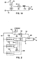
- FIGURE 1 shows an electric arc welder 10 for applying a D.C. welding current I a to a switching type welding station 12 having transistor type switches Q1, Q2 for passing the welding current across an electrode 14 and a workpiece 16.
- the seam is formed by two ends of a pipe section to be welded together or the elongated seam of a pipe mill.
- the electric arc welder has a plurality of inverter type power supplies, two of which are shown in FIGURE 1 as power supply PSA and power supply PSB.
- Power supply PSA is a unique power supply used by assignee, The Lincoln Electric Company, which allows implementation of the present invention for applying a D.C. current at the input of welding station 12.
- Power supply PSA includes an inverter 20 of the switching type having a standard high frequency switching network for providing a D.C. current from output stage 22 by energy from rectifier 24 driven by a standard three phase line voltage L1, L2 and L3.
- Output stage 22 creates a D.C. current across the input terminals 30, 32 of welding station 12.
- the output stage has transformer 40 with primary winding 42 and secondary winding 44 with a grounded center tap 46.
- Rectifier stage 50 includes diode 52, 54, 56 and 58, poled as shown in FIGURE 1, to create the D.C.
- Controller 100 has a standard command input signal which may be analog illustrated as the output of potentiometer 102 to control the voltage on line 104. Such analog command signal is used by controller 100 to determine the output operation of welding station 12. The analog voltage is converted from to digital at controller 100. In the preferred implementation of the present invention, the command signal is a digital signal on line 110 directed to controller 100.
- a somewhat standard feedback circuit utilizes a welding current sensor 120, illustrated as a shunt, for providing a voltage representative of the arc current in line 122. This analog signal is directed to controller 100 where it is converted into a digital signal for processing in accordance with standard software.
- a digitally implemented error amplifier type circuit 150 receives a command signal controlled by the signal on line 104 or line 110 to form additional value on the first input line 152 to error amplifier 150.
- the other input 154 is a digital signal from converter 156 where the analog representation in line 122 is converted to a digital number.
- the two digital numbers in lines 152, 154 are processed in accordance with standard technology represented schematically as error amplifier 150 to create the master current signal, which is a digital number in line 80.
- Welding station 12 includes transistor type switches Q1 and Q2, such as IGBTs, that are shifted between the conductive and non-conductive state. The size of the switches is selected to accommodate the total weld current. Gate logic on lines 170, 172 is created by controller 100 of PSA.
- the controller also generates a synchronizing output on line 180 for use in coordinating a number of separate welders of either standard design or using the present invention as shown in FIGURE 6.
- a synchronizing output on line 180 for use in coordinating a number of separate welders of either standard design or using the present invention as shown in FIGURE 6.
- power supply PSA which is considered as the "master” power supply, provides D.C. current to terminals 30, 32 in accordance with the master current signal in line 80.
- the invention employs a plurality of power supplies which includes at least one slave power supply illustrated as power supply PSB.
- This slave power supply is essentially the same as master power supply PSA, except it does not have a separate controller 100 or a separate feedback circuit. Consequently, PSB includes a standard switching type converter 200, like inverter 20, having an output stage 202 which is essentially the same as output stage 22 of inverter 20. D.C.
- power supply PSB includes a rectifier 210 driven by three phase line voltage L1, L2 and L3 in a manner that the pulses on input line 212 controls pulse width modulator 220 operated at a high frequency, in excess of 18 kHz controlled by the frequency of oscillator 222.
- Output current across lines 204, 206 is controlled by the voltage forming master current digital signal on line 80 changed to an analog signal by converter 224.
- the invention anticipates the use of more than two power supplies in electric arc welder 10.
- line 80 on which is carried the master current signal is shown as being extended.
- This line is used to control a third power supply PSC, as shown in FIGURE 2.
- the third power supply creates its own current in lines 230, 232 connected in parallel to input terminals 30, 32.
- the welding station 12 is controlled by a command signal on lines 104 or 110.
- the digital feedback circuit applies the sensed arc current in a digital format represented by line 154 for comparison with the digital information on line 152 to create the digital master current signal represented by line 80.
- the "lines" on FIGURE 1 are representative of software processing of digital data.
- the master current signal is representative of the difference between the desired current and the actual output current. This signal will be generally the reciprocal of the number of power supply units in electric arc welder 10.
- the master current signal is a signal asking each of the power supplies for one half of the desired current.
- the master current signal asks each power supply for one third of the desired current.
- each of the power supplies will provide the same amount of current, which currents are added at terminals 30, 32 for providing the desired welding current.
- Welder 10 has excellent static and dynamic current sharing capabilities and allows a large number of power supplies with small current ratings to be combined to produce high output currents for electric arc welder 10.
- the operation of arc welder 10 is schematically illustrated in FIGURE 3 wherein graph 300 is the total arc welding current comprising 50% from power supply PSA represented by curve 302 and 50% from power supply PSB represented by curve 304.
- each of the power supplies produces an equal share of the total current.
- a single feedback circuitry adjusts this current level.
- FIGURE 1A illustrates a slight modification of the welding station 12 of electric arc welder 10. Even though the welding station is not a part of the invention, an alternative welding station 12a is shown. In this station, transistor type switches Q1, Q2 provide welding current I a to an output circuit including a series choke 174a, instead of a center tap choke 174 used in the preferred embodiment. Both embodiments of the welding station use a plurality of power supplies, such as PBSA, PBSB, PBSC, etc.
- each of the power supplies is provided with a circuit to prevent over current, especially during startup.
- the circuit used for the power supplies is illustrated for use in power supply PSA. In practice, this same circuit is used for all of the power supplies.
- Pulse width modulator 70 has a standard anti-core saturation circuit actuated by the level of voltage on terminal AS.
- Output transformer 40 has a current transformer 320 for sensing the primary winding current I P as indicated by box 322.
- the voltage on line 324 has a voltage representing the primary winding current.
- the anti-choke saturation circuit in the PWM chip blocks operation of one of the switches or FET in inverter 20 to reduce the output current at primary winding 42.
- the output current of power supply is limited to prevent over current operation.
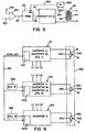
- FIGURES 6 and 7 show two separate electric arc welders 10, and 10a both constructed in accordance with the invention.
- Welder 10b is a standard welder having only the master power supply.
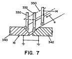
- Welders 10, 10a and 10b are used in pipe welding wherein three electrodes 14, 330 and 332 are moved along the gap between plates 340, 342 constituting workpiece 16.
- the electrodes are illustrated as being side-by-side as well as tandem and are held for unitary movement by carriage 350, illustrated as a dashed line structure.
- the three electrodes are held together by a carriage 350 that is moved in the direction indicated by arrow a in the joint between plates 340, 342.
- the three electrodes are illustrated as driven by the three separate electric arc welders 10, 10a and 10b to provide a unitary welding operation.
- a single electrode, side-by-side electrodes and/or a tandem arrangement of two or more electrodes can be used with separate electric arc welders.
- the welding stations 12 are operated at either different frequencies or at the same frequency with an adjusted phase indicated by 360, 362 in FIGURE 6.
- Each of the welders 10, 10a and 10b includes its own controller 100, 100a and 100b that controls the frequency of the gate logic signals on lines 170, 172.
- Synchronizing signal 180 controls the starting position of the output current pulses by use of controllers 100a and 100b.
- phase or offset is adjusted at welders 10a and 10b by phase adjustments 360, 362.
- the low frequency switching of the transistor type switches Q1, Q2 is at a different phase for all welders. This prevents interference between the current driving the electrodes.
- various modifications can be made in the preferred embodiment such as the selection of the number of power supplies driven by the single master current signal and the type of welding stations and electrode arrangements. They can be operated analog or digital.
- the processing format is digital; however, it is shown and can be analog. Indeed, PWM clips 70, 220 are analog. They can be digitized in subsequent generation of the invention.
Landscapes
- Engineering & Computer Science (AREA)
- Physics & Mathematics (AREA)
- Plasma & Fusion (AREA)
- Mechanical Engineering (AREA)
- Generation Of Surge Voltage And Current (AREA)
- Arc Welding Control (AREA)
Abstract
Description
- The present invention relates to the art of electric arc welding and more particularly to an improved electric arc welder constituting a plurality of separate power supplies.
- The invention is particularly applicable for use with an output welding station having two transistor type switches for converting a D.C. current into an A.C. welding current. Consequently, it is a secondary aspect of the invention that the switching of the transistor type switches between the conductive state and the non-conductive state be accomplished at a reduced current to alleviate the need for a large snubber circuit around each output switch. This concept, together with the type of inverter power supply used in practicing the present invention, is disclosed in prior United State application Serial No. 233,235 filed January 19, 1999. This application is incorporated by reference herein for background information regarding the type of inverter power supply used in the present invention and the concept of turning the transistor type switches of the welding station off at a reduced current level. The invention controls a switching type welding station with high current inputs. The switches are turned off only when a lower current is flowing.
- The present invention is particularly applicable to use in pipe welding and particularly for tandem electrodes or side-by-side electrodes used in pipe welding and it will be described with particular reference thereto; however, the invention has much broader applications and may be used for single electrode electric arc welders requiring extremely high current levels, such as welding currents exceeding about 1000-2000 amperes.
- Electric arc welders for pipe welding and other similar applications often require welding currents in excess of 1000-2000 amperes. In the past, welders for developing such high welding currents were specially designed. However, when the required welding current increased beyond the design parameters of a particular power supply, a higher capacity electric arc welder had to be designed and manufactured. For instance, electric arc welders having a maximum current of 1000-1500 amperes could not be used for a welding operation requiring 2000 amperes. As soon as a higher capacity welder was manufacture and made available, it was again limited by its maximum current capacity. Consequently, as increased current levels were demanded for a welding application, such as pike welding, custom design, expensive welders were often necessitated.
- Since higher welding currents required newly designed and manufactured welders, field applications could not be optimized due to the limited current capacity of the available power supply. Attempts have been made to create a high capacity welders by connecting a plurality of low capacity welders to the output welding station. Such attempts were not successful because there was difficulty balancing the dynamic current sharing capabilities of two or more separate power supplies.
- Disadvantages of the prior attempts to provide high current power supplies, especially for pipe welding, have been overcome by the present invention which creates an electric arc welder that has an output current capability that is increased drastically by merely adding a plurality of power supplies, while still obtaining excellent static and dynamic current sharing capabilities between the paralleled power supplies. The electric arc welder of the present invention minimizes unequal current sharing between two or more power supplies. In prior schemes the power supplies each required an input command signal, its own feedback and error amplifier control circuit. They, thus suffer from lack of dynamic current shared between the power supplies due to component variations. The present invention utilizes the error amplifier of one power supply that not only controls the power supply, referred to as a master power supply, but also directs the same master current signal to the other power supplies. The other power supplies of the welder do not have their own command signal or error amplifier control circuitry. Consequently, only one error amplifier and feedback control circuit is provided in the electric arc welder. An error amplifier and feedback circuit is not used for each of the individual power supplies being parallel to increase the current capabilities.
- In accordance with the present invention, there is provided an electric arc welder comprising a plurality of power supplies for creating a D.C. current of a given magnitude, which current is controlled by a single adjustable command signal. The D.C. current is used by a welding station having a D.C. input current and an output to pass an electric arc welding current between an electrode and a workpiece. A sensor, such as a shunt, senses the arc current. The plurality of power supplies includes a master power supply and one or more slave power supplies. The master power supply includes a first high speed switching type inverter having an output transformer and an output rectifier to produce a first D.C. current having a magnitude determined by a master current signal and a first pulse width modulator operated at a high frequency and having a current control voltage input controlled by the master current signal and an error amplifier for creating the master current signal based upon a comparison of the single command signal and the sensed arc current at the output of the welding station. The master power supply thus includes a command signal and an error amplifier feedback control circuit for controlling the pulse width modulator in the master power supply. The plurality of power supplies forming the welder includes at least one slave power supply which also includes a switching type inverter having an output transformer and an output rectifier to produce a second D.C. current having a magnitude determined by the same master current signal as used in the master power supply and a second pulse width modulator operated at a high frequency and having a current control voltage input connected to the master current signal of the master power supply. In this manner, the first and second D.C. currents combine to form at least a portion of the D.C. input current of the welding station. In practice, if two power supplies constitute the "plurality of power supplies" of the electric arc welder, the first D.C. current is 50% of the needed input current. The second D.C. current from the slave power supply provides the other 50% of the current. If three power supplies are used in the electric arc welder, each of the power supplies provides 33.3% of the input current for the output welding station. Consequently, the number of power supplies in the electric arc welder automatically determines the proportion of the D.C. current used to drive the welding station with the current being automatically balanced since each of the power supplies uses the same master current signal for the input of its pulse width modulator. A single command signal is used for the electric arc welder and only a single feedback circuitry is employed. By utilizing these novel concepts, a number of relatively small power supplies, such as 500 ampere power supplies, can be combined in any number to produce the desired maximum welding current. Six small power supplies, each rated for a maximum of 500 amperes, is combined to produce a 3000 ampere welding current. The ability to combine smaller power supplies to create an electric arc welder with an extremely high output welding current is obtained by the present invention. There is no need to design a power supply each time the current demand is increased.
- In accordance with another aspect of the present invention, the high frequency used for the pulse width modulator of the individual power supplies is at least 18 kHz. In addition, the individual welding station driven by the plurality of power supplies includes first and second transistor type switches, such as 1 GBTs, shifted between a conductive state and a non-conductive state by the gate logic on a pair of control lines. In accordance with a secondary aspect of the invention, the switches are not shifted from the conductive state to a non-conductive state until the arc current is less than a given value. In practice, this given value is about 100-150 amperes. The invention uses a single welding station for a plurality of power supplies so large switches are needed and a single controller creates the logic signal to shift from conductive to non-conductive at the selected given value. The master power supply controls the switching and the slave or slaves merely add welding current.
- In accordance with still a further aspect of the present invention, the output transformer in each of the power supplies includes a winding, specifically a primary winding, a current sensor associated with the winding and a circuit associated with the pulse width modulator of the individual power supply to hold at least one of the switches non-conductive for a time when the current in the winding exceeds a given current. This is referred to as the anti-core saturation circuit incorporated into a standard pulse width modulator chip and is used to prevent over current in the output welding station.
- In accordance with another aspect of the present invention, the novel electric arc welder is used with a tandem and/or side-by-side welding machine, such as a pipe welder.
- The primary object of the present invention is the provision of an electric arc welder which is assembled to produce high welding currents by combining a plurality of individual smaller power supplies while forcing the power supplies to share current equally.
- Yet another object of the present invention is the provision of an electric arc welder, as defined above, which electric arc welder incorporates a plurality of paralleled power supplies, while obtaining an excellent static and dynamic current sharing between power supplies.
- Still a further object of the present invention is the provision of an electric arc welder, as defined above, which electric arc welder uses a single current command signal, as well as a single error amplifier and feedback circuit, in analog or digital form, for controlling each of the individual power supplies to accurately share the current demands of the electric arc welder.
- These and other objects and advantages will become apparent from the following description taken together with the accompanying drawings.
-
- FIGURE 1 is a combined wiring diagram and block diagram illustrating the preferred embodiment of the present invention;
- FIGURE 2 is a simplified wiring diagram illustrating the preferred embodiment of the present invention when the welder uses more than two power supplies;
- FIGURE 3 is a graph showing the D.C. currents provided by a two power supply electric arc welder constructed in accordance with the present invention;
- FIGURE 4 is a graph similar to FIGURE 3 illustrating the current sharing deficiencies of the prior art;
- FIGURE 5 is a partial block diagram disclosing the use of an anti-core saturation circuit for the pulse width modulator chip of the individual power supplies used in FIGURE 1;
- FIGURE 6 is a block diagram showing the use of the present invention for both a tandem and a side-by-side arrangement of a plurality of electrodes used for pipe welding;
- FIGURE 7 is an enlarged partially cross sectioned view of side-by-side electrodes and a tandem mounted electrode for using the present invention as illustrated in FIGURE 5.
-
- Referring now to the drawings wherein the showings are for the purpose of illustrating preferred embodiments of the invention only and not for the purpose of limiting same, FIGURE 1 shows an
electric arc welder 10 for applying a D.C. welding current Ia to a switchingtype welding station 12 having transistor type switches Q1, Q2 for passing the welding current across anelectrode 14 and aworkpiece 16. The seam is formed by two ends of a pipe section to be welded together or the elongated seam of a pipe mill. The electric arc welder has a plurality of inverter type power supplies, two of which are shown in FIGURE 1 as power supply PSA and power supply PSB. Power supply PSA is a unique power supply used by assignee, The Lincoln Electric Company, which allows implementation of the present invention for applying a D.C. current at the input ofwelding station 12. Power supply PSA includes aninverter 20 of the switching type having a standard high frequency switching network for providing a D.C. current fromoutput stage 22 by energy fromrectifier 24 driven by a standard three phase line voltage L1, L2 and L3.Output stage 22 creates a D.C. current across theinput terminals welding station 12. The output stage hastransformer 40 with primary winding 42 and secondary winding 44 with a groundedcenter tap 46.Rectifier stage 50 includesdiode terminals input line 60 to a standardpulse width modulator 70 operated at high frequency. The high frequency is greater than 18 kHz and is controlled byoscillator 72. In practice digital format is used. Thus,input 74, which is analog, is provided with D/A converter 76. Pulses online 60 control the outputs D.C. current atterminals line 80. Consequently, the magnitude of the voltage online 80 determines the D.C. current applied by power supply PSA to inputterminals welding station 12. In accordance with the invention, the master current signal inline 80 is created bycontroller 100 which is a digital control circuit. Consequently, analog signals tocontroller 100 must be converted. The use of a digital representation of voltage online 80 is preferred. The digital form allows transmission with little noise.Controller 100 has a standard command input signal which may be analog illustrated as the output ofpotentiometer 102 to control the voltage online 104. Such analog command signal is used bycontroller 100 to determine the output operation ofwelding station 12. The analog voltage is converted from to digital atcontroller 100. In the preferred implementation of the present invention, the command signal is a digital signal online 110 directed tocontroller 100. A somewhat standard feedback circuit utilizes a weldingcurrent sensor 120, illustrated as a shunt, for providing a voltage representative of the arc current inline 122. This analog signal is directed tocontroller 100 where it is converted into a digital signal for processing in accordance with standard software. A digitally implemented erroramplifier type circuit 150 receives a command signal controlled by the signal online 104 orline 110 to form additional value on thefirst input line 152 toerror amplifier 150. Theother input 154 is a digital signal fromconverter 156 where the analog representation inline 122 is converted to a digital number. The two digital numbers inlines error amplifier 150 to create the master current signal, which is a digital number inline 80.Welding station 12 includes transistor type switches Q1 and Q2, such as IGBTs, that are shifted between the conductive and non-conductive state. The size of the switches is selected to accommodate the total weld current. Gate logic onlines controller 100 of PSA. This type of structure is illustrated in prior application Serial No. 233,235 incorporated by reference herein. The controller also generates a synchronizing output online 180 for use in coordinating a number of separate welders of either standard design or using the present invention as shown in FIGURE 6. By using the software of asingle controller 100, the reduced switch current feature is possible. - As so far described, power supply PSA, which is considered as the "master" power supply, provides D.C. current to
terminals line 80. The invention employs a plurality of power supplies which includes at least one slave power supply illustrated as power supply PSB. This slave power supply is essentially the same as master power supply PSA, except it does not have aseparate controller 100 or a separate feedback circuit. Consequently, PSB includes a standardswitching type converter 200, likeinverter 20, having anoutput stage 202 which is essentially the same asoutput stage 22 ofinverter 20. D.C. current inlines terminals welding station 12 so that the current from PSA and the current from PSB are combined to provide the input current for the welding station. As in power supply PSA, power supply PSB includes arectifier 210 driven by three phase line voltage L1, L2 and L3 in a manner that the pulses oninput line 212 controlspulse width modulator 220 operated at a high frequency, in excess of 18 kHz controlled by the frequency ofoscillator 222. Output current acrosslines line 80 changed to an analog signal byconverter 224. The invention anticipates the use of more than two power supplies inelectric arc welder 10. Thus,line 80 on which is carried the master current signal is shown as being extended. This line is used to control a third power supply PSC, as shown in FIGURE 2. The third power supply creates its own current inlines terminals - In operation, the
welding station 12 is controlled by a command signal onlines line 154 for comparison with the digital information online 152 to create the digital master current signal represented byline 80. Of course, the "lines" on FIGURE 1 are representative of software processing of digital data. The master current signal is representative of the difference between the desired current and the actual output current. This signal will be generally the reciprocal of the number of power supply units inelectric arc welder 10. As illustrated in FIGURE 1, the master current signal is a signal asking each of the power supplies for one half of the desired current. In FIGURE 2, the master current signal asks each power supply for one third of the desired current. Consequently, each of the power supplies will provide the same amount of current, which currents are added atterminals Welder 10 has excellent static and dynamic current sharing capabilities and allows a large number of power supplies with small current ratings to be combined to produce high output currents forelectric arc welder 10. The operation ofarc welder 10 is schematically illustrated in FIGURE 3 whereingraph 300 is the total arc welding current comprising 50% from power supply PSA represented bycurve curve 304. By using a single digital master current signal represented byline 80 for controlling all power supplies constituting the welder, each of the power supplies produces an equal share of the total current. A single feedback circuitry adjusts this current level. Small power supplies can be combined to produce a welder having output currents in excess of 2000-3000 amperes. In the prior art, as shown in FIGURE 4, the output currents from paralleled power supplies having their own command signal,controller 100 and feedback circuitry results ingraphs - FIGURE 1A illustrates a slight modification of the
welding station 12 ofelectric arc welder 10. Even though the welding station is not a part of the invention, analternative welding station 12a is shown. In this station, transistor type switches Q1, Q2 provide welding current Ia to an output circuit including aseries choke 174a, instead of acenter tap choke 174 used in the preferred embodiment. Both embodiments of the welding station use a plurality of power supplies, such as PBSA, PBSB, PBSC, etc. - In the preferred embodiment of the present invention, each of the power supplies is provided with a circuit to prevent over current, especially during startup. The circuit used for the power supplies is illustrated for use in power supply PSA. In practice, this same circuit is used for all of the power supplies.
Pulse width modulator 70 has a standard anti-core saturation circuit actuated by the level of voltage on terminal AS.Output transformer 40 has acurrent transformer 320 for sensing the primary winding current IP as indicated bybox 322. The voltage online 324 has a voltage representing the primary winding current. As the voltage online 324 increases beyond a certain level, the anti-choke saturation circuit in the PWM chip blocks operation of one of the switches or FET ininverter 20 to reduce the output current at primary winding 42. Thus, in accordance with standard practice, the output current of power supply is limited to prevent over current operation. - As illustrated in FIGURES 6 and 7, the present invention has substantial versatility and can be used in many applications requiring high welding currents. FIGURES 6 and 7 show two separate
electric arc welders Welders electrodes plates workpiece 16. The electrodes are illustrated as being side-by-side as well as tandem and are held for unitary movement bycarriage 350, illustrated as a dashed line structure. The three electrodes are held together by acarriage 350 that is moved in the direction indicated by arrow a in the joint betweenplates electric arc welders welding stations 12 are operated at either different frequencies or at the same frequency with an adjusted phase indicated by 360, 362 in FIGURE 6. Each of thewelders own controller lines signal 180 controls the starting position of the output current pulses by use ofcontrollers welders 10a and 10b byphase adjustments - The processing format is digital; however, it is shown and can be analog. Indeed, PWM clips 70, 220 are analog. They can be digitized in subsequent generation of the invention.
Claims (12)
- An electric arc welder comprising plurality of power supplies (PSA, PSB, PSC) for creating a D.C. current of a given magnitude controlled by an adjustable command signal for use by a welding station (12) having a D.C. input current and an output to pass an arc welding current (Ia) between an electrode (14, 330, 332) and workpiece (16, 340, 342) and an arc current sensor (120), said plurality of power supplies (PSA, PSB, PSC) including a first master power supply (PSA) including a first high speed switching type inverter (20) having an output transformer (40) and an output rectifier (50) to produce a first D.C. current having a magnitude determined by a master current signal and a first pulse width modulator (70) operated at a high frequency and having a current control voltage input (74) connected to said master current signal, and an error amplifier (150) for creating said master current signal based upon a comparison of said command signal and said sensed arc current, said plurality of power supplies (PSA, PSB, PSC) also including a first slave power supply (PSB) including a second high speed switching type inverter (200) having an output transformer and an output rectifier (202) to produce a second D.C. current having a magnitude determined by said master current signal and a second pulse width modulator (220) operated at a high frequency and having a current control voltage input connected to said master current signal of said master power supply (PSA) whereby said first and second D.C. currents combine to form at least a portion of said D.C. input current.
- An electric arc welder as defined in claim 1 wherein said plurality of power supplies (PSA, PSB, PSC) includes at least a second slave power supply (PSC) including a third high speed switching type inverter having an output transformer and an output rectifier to produce a third D.C. current having a magnitude determined by said master current signal and a third pulse width modulator operated at a high frequency and having a current control voltage input connected to said master current signal of said master power supply (PSA) whereby said first, second and third D.C. currents combine to form at least a portion of said D.C. input current.
- An electric arc welder as defined in claim 1 or 2 wherein said output transformer (40) in said power supplies (PSA, PSB, PSC) includes a winding (42), a current sensor (320) associated with said winding (42) and a circuit associated with the pulse width modulator (70, 220) of said power supply (PSA, PSB, PSC) to hold at least one of said switches (Q1, Q2) non-conductive for a time when said current (Ia) in said winding (42) exceeds a given current.
- A circuit for controlling, in accordance with an adjustable command signal, a plurality of power supplies (PSA, PSB, PSC) each operated by the voltage directed to the input of a pulse width modulator (70, 220) and connected to a common welding station (12) having a D.C. input current and an output to pass an arc welding current (Ia) between an electrode (14, 330, 332) and workpiece (16, 340, 342) and an arc current sensor (120), said circuit comprises an error amplifier (150) for creating a master current voltage signal based upon a comparison of a command signal and said sensed arc current and a distribution circuit connecting said master current voltage signal to input of the pulse width modulators (70, 220) of said power supplies (PSA, PSB, PSC) whereby each power supply (PSA, PSB, PSC) provides a proportional D.C. current to said common welding station (12) inversely proportional to the number of power supplies (PSA, PSB, PSC) in said plurality.
- An electric arc welder comprising a plurality of power supplies (PSA, PSB, PSC) connected to a single welding station (12) with a D.C. input for passing an arc welding current (Ia) across an electrode (14, 330, 332) and workpiece (16, 340, 342), each of said power supplies (PSA, PSB, PSC) including a switching type inverter (20, 200) with an output D.C. current determined by a signal applied to the input of said power supply (PSA, PSB, PSC), a circuit connecting said output D.C. currents in parallel at the input of said welding station (12), a feedback circuit including a sensor (120) for creating a current signal representing said arc current (Ia), a command signal source (100), and a circuit (150) for creating a master current signal based upon said sensed current signal and said command signal, and a circuit for applying said master current signal to the input of said plurality of power supplies (PSA, PSB, PSC) whereby the D.C. current to said D.C. input of said welding station is equally shared by said power supplies.
- A device as defined in any of the claims 1 to 5 wherein said welding current is an A.C. current.
- A device as defined in any of the claims 1 to 6 wherein said high frequency is at least about 18 kHz.
- A device as defined in any of the claims 1 to 7 wherein said welding station (12) includes first and second transistor type switches (Q1, Q2) shifted between a conductive state and a non-conductive state by the gate logic on a control line (172).
- A device as defined in claim 8 including means for shifting said switches (Q1, Q2) from the conductive state to the non-conductive state only when said arc current (Ia) is less than a given value.
- A device as defined in claim 9 wherein said given value is about 100-150 amperes.
- A device as defined in any of the claims 1 to 10 wherein said electrode (14, 330, 332) is one of a plurality of electrodes (14, 330, 332) in a tandem and/or a side-by-side welding machine.
- A device as defined in any of the claims 1 to 11 where in said welding machine is a pipe welder.
Applications Claiming Priority (2)
| Application Number | Priority Date | Filing Date | Title |
|---|---|---|---|
| US406406 | 1982-08-09 | ||
| US09/406,406 US6291798B1 (en) | 1999-09-27 | 1999-09-27 | Electric ARC welder with a plurality of power supplies |
Publications (3)
| Publication Number | Publication Date |
|---|---|
| EP1086773A2 true EP1086773A2 (en) | 2001-03-28 |
| EP1086773A3 EP1086773A3 (en) | 2002-07-17 |
| EP1086773B1 EP1086773B1 (en) | 2006-02-01 |
Family
ID=23607847
Family Applications (1)
| Application Number | Title | Priority Date | Filing Date |
|---|---|---|---|
| EP00120968A Expired - Lifetime EP1086773B1 (en) | 1999-09-27 | 2000-09-27 | Electric arc welder with a plurality of power supplies |
Country Status (15)
| Country | Link |
|---|---|
| US (1) | US6291798B1 (en) |
| EP (1) | EP1086773B1 (en) |
| JP (1) | JP3537754B2 (en) |
| KR (1) | KR100378939B1 (en) |
| CN (2) | CN100341655C (en) |
| AU (1) | AU739090B2 (en) |
| CA (1) | CA2319933C (en) |
| DE (1) | DE60025777T2 (en) |
| DZ (1) | DZ3094A1 (en) |
| EG (1) | EG22160A (en) |
| ID (1) | ID27327A (en) |
| RU (2) | RU2211124C2 (en) |
| SA (1) | SA00210587B1 (en) |
| TW (1) | TW503149B (en) |
| ZA (1) | ZA200005187B (en) |
Cited By (4)
| Publication number | Priority date | Publication date | Assignee | Title |
|---|---|---|---|---|
| WO2002047861A1 (en) * | 2000-12-15 | 2002-06-20 | Fronius International Gmbh | Method for connecting several welding devices and corresponding welding device |
| WO2002083351A1 (en) | 2001-04-17 | 2002-10-24 | Lincoln Global, Inc. | Electric arc welding system |
| EP1295668A1 (en) * | 2001-09-19 | 2003-03-26 | Illinois Tool Works Inc. | Method of designing and manufacturing welding-type systems |
| DE102008051844A1 (en) * | 2008-10-17 | 2010-04-22 | Ess Schweißtechnik GmbH | Electric power source for the supply of electric power to workpiece-processing device and/or workpiece processing process, comprises a digital processing control unit for a process parameter, a power section and a bus distributor |
Families Citing this family (66)
| Publication number | Priority date | Publication date | Assignee | Title |
|---|---|---|---|---|
| AU2006200414B2 (en) * | 2001-04-17 | 2009-11-19 | Lincoln Global, Inc. | Electric arc welding system |
| US6700097B1 (en) | 2001-09-28 | 2004-03-02 | Lincoln Global, Inc. | Electric ARC welder and controller to design the waveform therefor |
| US7091445B2 (en) | 2002-10-25 | 2006-08-15 | Lincoln Global, Inc. | Electric arc welder and method for controlling the welding process of the welder |
| US6847008B2 (en) | 2003-01-17 | 2005-01-25 | Lincoln Global, Inc. | Electric arc welding system |
| US7105772B2 (en) * | 2003-03-24 | 2006-09-12 | Lincoln Global, Inc. | Arc welding system and method |
| US7274000B2 (en) * | 2003-07-11 | 2007-09-25 | Lincoln Global, Inc. | Power source for high current welding |
| US7091446B2 (en) * | 2003-12-15 | 2006-08-15 | Lincoln Global, Inc. | Electric arc welding system |
| US6940039B2 (en) * | 2003-12-22 | 2005-09-06 | Lincoln Global, Inc. | Quality control module for tandem arc welding |
| US8895896B2 (en) | 2004-01-12 | 2014-11-25 | Lincoln Global, Inc. | Modified series arc welding and improved control of one sided series arc welding |
| US9579742B2 (en) * | 2006-01-09 | 2017-02-28 | Lincoln Global, Inc. | Series arc welder |
| US7105773B2 (en) | 2004-01-12 | 2006-09-12 | Lincoln Global, Inc. | Electric arc welder |
| US7053334B2 (en) * | 2004-03-01 | 2006-05-30 | Lincoln Global, Inc. | Electric arc welder system with waveform profile control |
| US7294808B2 (en) * | 2004-03-15 | 2007-11-13 | Lincoln Global, Inc. | Remote wire feeder |
| US20070215585A1 (en) * | 2006-03-15 | 2007-09-20 | Lincoln Global, Inc. | High current AC welder |
| US20070221643A1 (en) * | 2004-04-29 | 2007-09-27 | Lincoln Global, Inc. | Gas-less process and system for girth welding in high strength applications including liquefied natural gas storage tanks |
| US9333580B2 (en) * | 2004-04-29 | 2016-05-10 | Lincoln Global, Inc. | Gas-less process and system for girth welding in high strength applications |
| US7842903B2 (en) | 2005-10-31 | 2010-11-30 | Lincoln Global, Inc. | Short arc welding system |
| US8704135B2 (en) | 2006-01-20 | 2014-04-22 | Lincoln Global, Inc. | Synergistic welding system |
| US7166817B2 (en) * | 2004-04-29 | 2007-01-23 | Lincoln Global, Inc. | Electric ARC welder system with waveform profile control for cored electrodes |
| US8759715B2 (en) | 2004-10-06 | 2014-06-24 | Lincoln Global, Inc. | Method of AC welding with cored electrode |
| US9956639B2 (en) | 2005-02-07 | 2018-05-01 | Lincoln Global, Inc | Modular power source for electric ARC welding and output chopper |
| US8785816B2 (en) | 2004-07-13 | 2014-07-22 | Lincoln Global, Inc. | Three stage power source for electric arc welding |
| US8581147B2 (en) | 2005-03-24 | 2013-11-12 | Lincoln Global, Inc. | Three stage power source for electric ARC welding |
| US8269141B2 (en) | 2004-07-13 | 2012-09-18 | Lincoln Global, Inc. | Power source for electric arc welding |
| JP2006116556A (en) * | 2004-10-19 | 2006-05-11 | Sansha Electric Mfg Co Ltd | Power supply device of arc applying equipment |
| US9855620B2 (en) | 2005-02-07 | 2018-01-02 | Lincoln Global, Inc. | Welding system and method of welding |
| US7495193B2 (en) * | 2005-03-15 | 2009-02-24 | Lincoln Global, Inc. | Pipe seam tack welding methods and apparatus using modified series arc welding |
| US7968822B2 (en) * | 2005-03-28 | 2011-06-28 | Lincoln Global, Inc. | Arc welding system |
| US9647555B2 (en) | 2005-04-08 | 2017-05-09 | Lincoln Global, Inc. | Chopper output stage for arc welder power source |
| US8680432B2 (en) * | 2005-04-20 | 2014-03-25 | Illinois Tool Works Inc. | Cooperative welding system |
| US7989732B2 (en) * | 2005-06-15 | 2011-08-02 | Lincoln Global, Inc. | Method of AC welding using a flux cored electrode |
| WO2007053137A1 (en) * | 2005-10-31 | 2007-05-10 | Lincoln Global, Inc. | Electric arc welder |
| US8525077B2 (en) * | 2006-05-09 | 2013-09-03 | Lincoln Global, Inc. | Touch screen waveform design apparatus for welders |
| US20080011727A1 (en) * | 2006-07-14 | 2008-01-17 | Lincoln Global, Inc. | Dual fillet welding methods and systems |
| US8242410B2 (en) | 2006-07-14 | 2012-08-14 | Lincoln Global, Inc. | Welding methods and systems |
| US9095929B2 (en) | 2006-07-14 | 2015-08-04 | Lincoln Global, Inc. | Dual fillet welding methods and systems |
| US10010961B2 (en) * | 2006-07-17 | 2018-07-03 | Lincoln Global, Inc. | Multiple arc welding system controls and methods |
| US8963045B2 (en) * | 2006-09-19 | 2015-02-24 | Lincoln Global, Inc. | Non-linear adaptive control system and method for welding |
| US8946596B2 (en) | 2006-10-05 | 2015-02-03 | Lincoln Global, Inc. | Multiple welding using a single power source |
| US7586766B2 (en) * | 2006-12-15 | 2009-09-08 | Sansha Electric Manufacturing Co., Ltd. | Plasma arc power supply and control method for same |
| CN101147998B (en) * | 2007-11-01 | 2010-04-07 | 重庆润通动力有限公司 | Internal combustion direct current arc welding machine current regulator |
| US9044818B2 (en) * | 2007-11-08 | 2015-06-02 | Lincoln Global, Inc. | Method of welding two sides of a joint simultaneously |
| US8952293B2 (en) * | 2008-03-14 | 2015-02-10 | Illinois Tool Works Inc. | Welding or cutting power supply using phase shift double forward converter circuit (PSDF) |
| JP4831264B2 (en) * | 2009-02-25 | 2011-12-07 | パナソニック株式会社 | Welding method and welding system |
| US9333584B2 (en) * | 2009-03-19 | 2016-05-10 | Lincoln Global, Inc. | Modified phase shifted gate drive |
| US8640799B2 (en) * | 2009-06-11 | 2014-02-04 | Illinois Tool Works Inc. | Welding systems powered by hybrid vehicles |
| US8426772B2 (en) * | 2009-09-02 | 2013-04-23 | Lincoln Global, Inc. | Auxiliary power supply for a welding machine |
| SE534501C2 (en) * | 2009-09-22 | 2011-09-13 | Safetrack Infrasystems Sisab Ab | Method and device for stick soldering |
| SE534975C2 (en) * | 2009-10-16 | 2012-03-06 | Tsc Innovation Ab | Method and apparatus for installing and repairing insulated pipe lines |
| US8309878B2 (en) * | 2009-12-30 | 2012-11-13 | Itt Manufacturing Enterprises, Inc. | Universal input power supply utilizing parallel power modules |
| US9156103B2 (en) | 2010-06-17 | 2015-10-13 | Illinois Tool Works Inc. | Modular direct current power source |
| US10507542B2 (en) * | 2012-05-31 | 2019-12-17 | Illinois Tool Works Inc. | System and method for pairing welding devices |
| US10144083B2 (en) | 2013-02-22 | 2018-12-04 | Illinois Tool Works Inc. | Multi-operator engine driven welder system |
| KR200479118Y1 (en) * | 2014-08-21 | 2015-12-23 | 대우조선해양 주식회사 | Welding machine capable of managing welder and welding information |
| CN104467513A (en) * | 2014-12-05 | 2015-03-25 | 江门市保值久机电有限公司 | Pulse type welder power circuit |
| JP6745190B2 (en) | 2016-02-03 | 2020-08-26 | 株式会社ダイヘン | Power supply system and power supply |
| JP6650838B2 (en) | 2016-06-23 | 2020-02-19 | 株式会社ダイヘン | Power supply system, power supply, control method, and control program |
| US10060968B2 (en) * | 2016-08-26 | 2018-08-28 | Teradyne, Inc. | Combining current sourced by channels of automatic test equipment |
| JP6339651B1 (en) * | 2016-12-02 | 2018-06-06 | ファナック株式会社 | Arc welding robot system |
| JP6835676B2 (en) | 2017-07-05 | 2021-02-24 | 株式会社ダイヘン | Power system, power supply, control method and control program |
| DE102018000245B4 (en) * | 2018-01-15 | 2020-08-20 | Hbs Bolzenschweiss-Systeme Gmbh & Co. Kg | WELDING POWER GENERATING DEVICE |
| US10906117B2 (en) * | 2018-01-30 | 2021-02-02 | Illinois Tool Works Inc. | System and method for providing welding type power on multiple outputs |
| JP7202760B2 (en) * | 2018-11-30 | 2023-01-12 | 株式会社ダイヘン | AC arc welding control method |
| CN110233577B (en) * | 2019-07-02 | 2024-04-09 | 中国电子科技集团公司第四十三研究所 | Controllable high-voltage power pulse generation circuit and control method |
| US20210060680A1 (en) * | 2019-08-28 | 2021-03-04 | Lincoln Global, Inc. | Systems and methods providing coordinated dual power outputs supporting a same welding or auxiliary power process |
| JP7327870B2 (en) * | 2019-10-02 | 2023-08-16 | 株式会社ダイヘン | welding system |
Citations (6)
| Publication number | Priority date | Publication date | Assignee | Title |
|---|---|---|---|---|
| DE2628385A1 (en) * | 1976-06-24 | 1977-12-29 | Messer Griesheim Gmbh | Submerged arc welding using very high current - obtd. from several power supplies with automatic control of welding voltage |
| US4425613A (en) * | 1981-05-26 | 1984-01-10 | Sperry Corporation | Forced load sharing circuit for inverter power supply |
| US4503316A (en) * | 1981-08-13 | 1985-03-05 | Kabushiki Kaisha Kobe Seiko Sho | DC Welding power supply system |
| US5120929A (en) * | 1988-11-17 | 1992-06-09 | Honda Giken Kogyo Kabushiki Kaisha | Dc resistance welding apparatus |
| US6023037A (en) * | 1998-11-05 | 2000-02-08 | Lincoln Global, Inc. | Electric ARC welder and plasma cutter |
| EP1023965A2 (en) * | 1999-01-19 | 2000-08-02 | Lincoln Global, Inc. | High current welding power supply |
Family Cites Families (9)
| Publication number | Priority date | Publication date | Assignee | Title |
|---|---|---|---|---|
| FR2385486A1 (en) * | 1977-03-31 | 1978-10-27 | Petroles Cie Francaise | AUTOMATIC CHAMFERED TUBES WELDING METHOD AND MACHINE |
| SE438109B (en) * | 1983-11-28 | 1985-04-01 | Esab Ab | STROMKELLA FOR LIGHT REAR WELDING |
| US5001326A (en) | 1986-12-11 | 1991-03-19 | The Lincoln Electric Company | Apparatus and method of controlling a welding cycle |
| US4947021A (en) | 1987-12-29 | 1990-08-07 | The Lincoln Electric Company | Method and apparatus for TIG welding |
| US4861965A (en) | 1987-12-29 | 1989-08-29 | The Lincoln Electric Company | Method and apparatus for TIG welding |
| US5349157A (en) | 1993-01-04 | 1994-09-20 | The Lincoln Electric Company | Inverter power supply for welding |
| US5351175A (en) | 1993-02-05 | 1994-09-27 | The Lincoln Electric Company | Inverter power supply for welding |
| US5434768A (en) | 1993-02-12 | 1995-07-18 | Rompower | Fixed frequency converter switching at zero voltage |
| US5811757A (en) * | 1996-02-29 | 1998-09-22 | The Esab Group, Inc. | Power source including parallel switching circuits and related methods for a welding or cutting system |
-
1999
- 1999-09-27 US US09/406,406 patent/US6291798B1/en not_active Expired - Fee Related
-
2000
- 2000-09-18 CA CA002319933A patent/CA2319933C/en not_active Expired - Fee Related
- 2000-09-22 TW TW089119629A patent/TW503149B/en not_active IP Right Cessation
- 2000-09-22 AU AU61256/00A patent/AU739090B2/en not_active Ceased
- 2000-09-23 EG EG20001212A patent/EG22160A/en active
- 2000-09-26 RU RU2000124590/02A patent/RU2211124C2/en not_active IP Right Cessation
- 2000-09-27 CN CNB2004100841304A patent/CN100341655C/en not_active Expired - Fee Related
- 2000-09-27 JP JP2000293701A patent/JP3537754B2/en not_active Expired - Fee Related
- 2000-09-27 CN CNB001249592A patent/CN1247357C/en not_active Expired - Fee Related
- 2000-09-27 EP EP00120968A patent/EP1086773B1/en not_active Expired - Lifetime
- 2000-09-27 ID IDP20000834D patent/ID27327A/en unknown
- 2000-09-27 ZA ZA200005187A patent/ZA200005187B/en unknown
- 2000-09-27 KR KR10-2000-0056664A patent/KR100378939B1/en not_active IP Right Cessation
- 2000-09-27 DZ DZ000141A patent/DZ3094A1/en active
- 2000-09-27 DE DE60025777T patent/DE60025777T2/en not_active Expired - Lifetime
- 2000-12-02 SA SA00210587A patent/SA00210587B1/en unknown
-
2003
- 2003-04-18 RU RU2003111216/02A patent/RU2309029C2/en not_active IP Right Cessation
Patent Citations (6)
| Publication number | Priority date | Publication date | Assignee | Title |
|---|---|---|---|---|
| DE2628385A1 (en) * | 1976-06-24 | 1977-12-29 | Messer Griesheim Gmbh | Submerged arc welding using very high current - obtd. from several power supplies with automatic control of welding voltage |
| US4425613A (en) * | 1981-05-26 | 1984-01-10 | Sperry Corporation | Forced load sharing circuit for inverter power supply |
| US4503316A (en) * | 1981-08-13 | 1985-03-05 | Kabushiki Kaisha Kobe Seiko Sho | DC Welding power supply system |
| US5120929A (en) * | 1988-11-17 | 1992-06-09 | Honda Giken Kogyo Kabushiki Kaisha | Dc resistance welding apparatus |
| US6023037A (en) * | 1998-11-05 | 2000-02-08 | Lincoln Global, Inc. | Electric ARC welder and plasma cutter |
| EP1023965A2 (en) * | 1999-01-19 | 2000-08-02 | Lincoln Global, Inc. | High current welding power supply |
Cited By (8)
| Publication number | Priority date | Publication date | Assignee | Title |
|---|---|---|---|---|
| WO2002047861A1 (en) * | 2000-12-15 | 2002-06-20 | Fronius International Gmbh | Method for connecting several welding devices and corresponding welding device |
| US7041936B2 (en) * | 2000-12-15 | 2006-05-09 | Fronius International Gmbh | Method for connecting several welding devices and corresponding welding device |
| WO2002083351A1 (en) | 2001-04-17 | 2002-10-24 | Lincoln Global, Inc. | Electric arc welding system |
| EP1387732A1 (en) * | 2001-04-17 | 2004-02-11 | Lincoln Global, Inc. | Electric arc welding system |
| EP1387732A4 (en) * | 2001-04-17 | 2008-03-19 | Lincoln Global Inc | Electric arc welding system |
| EP1295668A1 (en) * | 2001-09-19 | 2003-03-26 | Illinois Tool Works Inc. | Method of designing and manufacturing welding-type systems |
| US6713721B2 (en) | 2001-09-19 | 2004-03-30 | Illinois Tool Works Inc. | Method of designing and manufacturing welding-type power supplies |
| DE102008051844A1 (en) * | 2008-10-17 | 2010-04-22 | Ess Schweißtechnik GmbH | Electric power source for the supply of electric power to workpiece-processing device and/or workpiece processing process, comprises a digital processing control unit for a process parameter, a power section and a bus distributor |
Also Published As
| Publication number | Publication date |
|---|---|
| US6291798B1 (en) | 2001-09-18 |
| SA00210587B1 (en) | 2006-08-20 |
| ID27327A (en) | 2001-03-29 |
| CN1247357C (en) | 2006-03-29 |
| CN1292314A (en) | 2001-04-25 |
| EP1086773A3 (en) | 2002-07-17 |
| KR100378939B1 (en) | 2003-04-08 |
| CA2319933C (en) | 2004-11-23 |
| DZ3094A1 (en) | 2004-06-20 |
| DE60025777D1 (en) | 2006-04-13 |
| AU6125600A (en) | 2001-03-29 |
| CA2319933A1 (en) | 2001-03-27 |
| DE60025777T2 (en) | 2006-11-09 |
| CN1603046A (en) | 2005-04-06 |
| RU2211124C2 (en) | 2003-08-27 |
| RU2309029C2 (en) | 2007-10-27 |
| RU2003111216A (en) | 2005-01-10 |
| KR20010030503A (en) | 2001-04-16 |
| EG22160A (en) | 2002-09-30 |
| TW503149B (en) | 2002-09-21 |
| ZA200005187B (en) | 2001-04-19 |
| CN100341655C (en) | 2007-10-10 |
| JP2001129667A (en) | 2001-05-15 |
| JP3537754B2 (en) | 2004-06-14 |
| AU739090B2 (en) | 2001-10-04 |
| EP1086773B1 (en) | 2006-02-01 |
Similar Documents
| Publication | Publication Date | Title |
|---|---|---|
| US6291798B1 (en) | Electric ARC welder with a plurality of power supplies | |
| EP1157772B1 (en) | Power supply for electric arc welding | |
| CA2497813C (en) | Power source for electric arc welding | |
| US6940040B2 (en) | Electric arc welding system | |
| US9956639B2 (en) | Modular power source for electric ARC welding and output chopper | |
| JPH06238444A (en) | Inverter power supply for welding | |
| JPH06234072A (en) | Inverter power supply for welding | |
| KR0113226Y1 (en) | Welding power source supplying circuit | |
| JPH0747177Y2 (en) | Aluminum welding equipment |
Legal Events
| Date | Code | Title | Description |
|---|---|---|---|
| PUAI | Public reference made under article 153(3) epc to a published international application that has entered the european phase |
Free format text: ORIGINAL CODE: 0009012 |
|
| AK | Designated contracting states |
Kind code of ref document: A2 Designated state(s): AT BE CH CY DE DK ES FI FR GB GR IE IT LI LU MC NL PT SE |
|
| AX | Request for extension of the european patent |
Free format text: AL;LT;LV;MK;RO;SI |
|
| PUAL | Search report despatched |
Free format text: ORIGINAL CODE: 0009013 |
|
| AK | Designated contracting states |
Kind code of ref document: A3 Designated state(s): AT BE CH CY DE DK ES FI FR GB GR IE IT LI LU MC NL PT SE |
|
| AX | Request for extension of the european patent |
Free format text: AL;LT;LV;MK;RO;SI |
|
| 17P | Request for examination filed |
Effective date: 20030115 |
|
| AKX | Designation fees paid |
Designated state(s): DE FR GB IT |
|
| 17Q | First examination report despatched |
Effective date: 20030318 |
|
| GRAJ | Information related to disapproval of communication of intention to grant by the applicant or resumption of examination proceedings by the epo deleted |
Free format text: ORIGINAL CODE: EPIDOSDIGR1 |
|
| GRAP | Despatch of communication of intention to grant a patent |
Free format text: ORIGINAL CODE: EPIDOSNIGR1 |
|
| GRAP | Despatch of communication of intention to grant a patent |
Free format text: ORIGINAL CODE: EPIDOSNIGR1 |
|
| GRAS | Grant fee paid |
Free format text: ORIGINAL CODE: EPIDOSNIGR3 |
|
| GRAA | (expected) grant |
Free format text: ORIGINAL CODE: 0009210 |
|
| AK | Designated contracting states |
Kind code of ref document: B1 Designated state(s): DE FR GB IT |
|
| REG | Reference to a national code |
Ref country code: GB Ref legal event code: FG4D |
|
| REF | Corresponds to: |
Ref document number: 60025777 Country of ref document: DE Date of ref document: 20060413 Kind code of ref document: P |
|
| ET | Fr: translation filed | ||
| PLBE | No opposition filed within time limit |
Free format text: ORIGINAL CODE: 0009261 |
|
| STAA | Information on the status of an ep patent application or granted ep patent |
Free format text: STATUS: NO OPPOSITION FILED WITHIN TIME LIMIT |
|
| 26N | No opposition filed |
Effective date: 20061103 |
|
| PGFP | Annual fee paid to national office [announced via postgrant information from national office to epo] |
Ref country code: FR Payment date: 20080917 Year of fee payment: 9 |
|
| REG | Reference to a national code |
Ref country code: FR Ref legal event code: ST Effective date: 20100531 |
|
| PG25 | Lapsed in a contracting state [announced via postgrant information from national office to epo] |
Ref country code: FR Free format text: LAPSE BECAUSE OF NON-PAYMENT OF DUE FEES Effective date: 20090930 |
|
| REG | Reference to a national code |
Ref country code: FR Ref legal event code: RN |
|
| PGFP | Annual fee paid to national office [announced via postgrant information from national office to epo] |
Ref country code: IT Payment date: 20100925 Year of fee payment: 11 |
|
| PGFP | Annual fee paid to national office [announced via postgrant information from national office to epo] |
Ref country code: GB Payment date: 20100927 Year of fee payment: 11 |
|
| PGFP | Annual fee paid to national office [announced via postgrant information from national office to epo] |
Ref country code: DE Payment date: 20100929 Year of fee payment: 11 |
|
| REG | Reference to a national code |
Ref country code: FR Ref legal event code: IC |
|
| GBPC | Gb: european patent ceased through non-payment of renewal fee |
Effective date: 20110927 |
|
| PG25 | Lapsed in a contracting state [announced via postgrant information from national office to epo] |
Ref country code: IT Free format text: LAPSE BECAUSE OF NON-PAYMENT OF DUE FEES Effective date: 20110927 |
|
| REG | Reference to a national code |
Ref country code: DE Ref legal event code: R119 Ref document number: 60025777 Country of ref document: DE Effective date: 20120403 |
|
| PG25 | Lapsed in a contracting state [announced via postgrant information from national office to epo] |
Ref country code: DE Free format text: LAPSE BECAUSE OF NON-PAYMENT OF DUE FEES Effective date: 20120403 |
|
| PG25 | Lapsed in a contracting state [announced via postgrant information from national office to epo] |
Ref country code: GB Free format text: LAPSE BECAUSE OF NON-PAYMENT OF DUE FEES Effective date: 20110927 |