EP1082601B1 - Flow-through shear analyzer for biologically active molecules in liquid layers on surfaces, method of analysing a liquid and method of determining the thickness of an ultra thick liquid layer - Google Patents
Flow-through shear analyzer for biologically active molecules in liquid layers on surfaces, method of analysing a liquid and method of determining the thickness of an ultra thick liquid layer Download PDFInfo
- Publication number
- EP1082601B1 EP1082601B1 EP99936304A EP99936304A EP1082601B1 EP 1082601 B1 EP1082601 B1 EP 1082601B1 EP 99936304 A EP99936304 A EP 99936304A EP 99936304 A EP99936304 A EP 99936304A EP 1082601 B1 EP1082601 B1 EP 1082601B1
- Authority
- EP
- European Patent Office
- Prior art keywords
- liquid
- sample chamber
- sample
- radiation
- chamber
- Prior art date
- Legal status (The legal status is an assumption and is not a legal conclusion. Google has not performed a legal analysis and makes no representation as to the accuracy of the status listed.)
- Expired - Lifetime
Links
- 239000007788 liquid Substances 0.000 title claims abstract description 108
- 238000000034 method Methods 0.000 title claims description 28
- 102000004169 proteins and genes Human genes 0.000 claims abstract description 43
- 108090000623 proteins and genes Proteins 0.000 claims abstract description 43
- 239000012530 fluid Substances 0.000 claims abstract description 38
- 238000001179 sorption measurement Methods 0.000 claims abstract description 27
- 238000004458 analytical method Methods 0.000 claims abstract description 25
- 238000006243 chemical reaction Methods 0.000 claims abstract description 13
- 239000000872 buffer Substances 0.000 claims abstract description 6
- 239000000523 sample Substances 0.000 claims description 75
- VYPSYNLAJGMNEJ-UHFFFAOYSA-N Silicium dioxide Chemical compound O=[Si]=O VYPSYNLAJGMNEJ-UHFFFAOYSA-N 0.000 claims description 49
- 239000010453 quartz Substances 0.000 claims description 39
- 239000007853 buffer solution Substances 0.000 claims description 34
- 230000005855 radiation Effects 0.000 claims description 23
- 239000000243 solution Substances 0.000 claims description 21
- 238000005259 measurement Methods 0.000 claims description 17
- 230000003287 optical effect Effects 0.000 claims description 16
- 239000007787 solid Substances 0.000 claims description 12
- 230000035515 penetration Effects 0.000 claims description 11
- 239000000463 material Substances 0.000 claims description 10
- 239000012488 sample solution Substances 0.000 claims description 10
- 239000003446 ligand Substances 0.000 claims description 9
- 238000002347 injection Methods 0.000 claims description 8
- 239000007924 injection Substances 0.000 claims description 8
- 238000011156 evaluation Methods 0.000 claims description 5
- 238000000576 coating method Methods 0.000 claims description 4
- 239000011248 coating agent Substances 0.000 claims description 3
- 230000002209 hydrophobic effect Effects 0.000 claims description 3
- 230000009467 reduction Effects 0.000 claims description 3
- 238000010008 shearing Methods 0.000 claims description 3
- 238000002336 sorption--desorption measurement Methods 0.000 claims description 2
- 230000008878 coupling Effects 0.000 claims 1
- 238000010168 coupling process Methods 0.000 claims 1
- 238000005859 coupling reaction Methods 0.000 claims 1
- 239000003365 glass fiber Substances 0.000 claims 1
- 230000001678 irradiating effect Effects 0.000 claims 1
- 239000007790 solid phase Substances 0.000 claims 1
- 230000001419 dependent effect Effects 0.000 abstract description 3
- 102000008946 Fibrinogen Human genes 0.000 description 9
- 108010049003 Fibrinogen Proteins 0.000 description 9
- 229940012952 fibrinogen Drugs 0.000 description 9
- 238000002156 mixing Methods 0.000 description 9
- 238000003795 desorption Methods 0.000 description 5
- 230000005284 excitation Effects 0.000 description 5
- 230000008569 process Effects 0.000 description 5
- 230000008859 change Effects 0.000 description 4
- 238000002474 experimental method Methods 0.000 description 4
- 239000000126 substance Substances 0.000 description 4
- PEDCQBHIVMGVHV-UHFFFAOYSA-N Glycerine Chemical compound OCC(O)CO PEDCQBHIVMGVHV-UHFFFAOYSA-N 0.000 description 3
- QIVBCDIJIAJPQS-VIFPVBQESA-N L-tryptophane Chemical compound C1=CC=C2C(C[C@H](N)C(O)=O)=CNC2=C1 QIVBCDIJIAJPQS-VIFPVBQESA-N 0.000 description 3
- QIVBCDIJIAJPQS-UHFFFAOYSA-N Tryptophan Natural products C1=CC=C2C(CC(N)C(O)=O)=CNC2=C1 QIVBCDIJIAJPQS-UHFFFAOYSA-N 0.000 description 3
- 150000001875 compounds Chemical class 0.000 description 3
- LDCYZAJDBXYCGN-VIFPVBQESA-N 5-hydroxy-L-tryptophan Chemical compound C1=C(O)C=C2C(C[C@H](N)C(O)=O)=CNC2=C1 LDCYZAJDBXYCGN-VIFPVBQESA-N 0.000 description 2
- 238000007792 addition Methods 0.000 description 2
- 230000007423 decrease Effects 0.000 description 2
- 238000009795 derivation Methods 0.000 description 2
- 238000009792 diffusion process Methods 0.000 description 2
- 239000007943 implant Substances 0.000 description 2
- 230000003993 interaction Effects 0.000 description 2
- 230000002829 reductive effect Effects 0.000 description 2
- 238000000926 separation method Methods 0.000 description 2
- 238000002198 surface plasmon resonance spectroscopy Methods 0.000 description 2
- 238000012546 transfer Methods 0.000 description 2
- 229910052724 xenon Inorganic materials 0.000 description 2
- FHNFHKCVQCLJFQ-UHFFFAOYSA-N xenon atom Chemical compound [Xe] FHNFHKCVQCLJFQ-UHFFFAOYSA-N 0.000 description 2
- 102000004506 Blood Proteins Human genes 0.000 description 1
- 108010017384 Blood Proteins Proteins 0.000 description 1
- 101100004280 Caenorhabditis elegans best-2 gene Proteins 0.000 description 1
- -1 For example Substances 0.000 description 1
- 208000007536 Thrombosis Diseases 0.000 description 1
- 238000010521 absorption reaction Methods 0.000 description 1
- 230000004913 activation Effects 0.000 description 1
- 230000001464 adherent effect Effects 0.000 description 1
- 239000003463 adsorbent Substances 0.000 description 1
- 238000013459 approach Methods 0.000 description 1
- 230000004888 barrier function Effects 0.000 description 1
- 230000004071 biological effect Effects 0.000 description 1
- 239000012620 biological material Substances 0.000 description 1
- 239000008280 blood Substances 0.000 description 1
- 210000004369 blood Anatomy 0.000 description 1
- 239000008364 bulk solution Substances 0.000 description 1
- 238000007385 chemical modification Methods 0.000 description 1
- 239000003795 chemical substances by application Substances 0.000 description 1
- 239000004020 conductor Substances 0.000 description 1
- 230000003247 decreasing effect Effects 0.000 description 1
- 230000008021 deposition Effects 0.000 description 1
- 238000001514 detection method Methods 0.000 description 1
- 238000011161 development Methods 0.000 description 1
- 238000010586 diagram Methods 0.000 description 1
- 238000006073 displacement reaction Methods 0.000 description 1
- 238000010494 dissociation reaction Methods 0.000 description 1
- 230000005593 dissociations Effects 0.000 description 1
- 239000003814 drug Substances 0.000 description 1
- 238000000572 ellipsometry Methods 0.000 description 1
- 238000005516 engineering process Methods 0.000 description 1
- 238000005188 flotation Methods 0.000 description 1
- 239000006260 foam Substances 0.000 description 1
- 238000005194 fractionation Methods 0.000 description 1
- 239000005556 hormone Substances 0.000 description 1
- 229940088597 hormone Drugs 0.000 description 1
- 230000002706 hydrostatic effect Effects 0.000 description 1
- 238000001727 in vivo Methods 0.000 description 1
- 230000002452 interceptive effect Effects 0.000 description 1
- 238000005305 interferometry Methods 0.000 description 1
- 238000011835 investigation Methods 0.000 description 1
- 150000002500 ions Chemical class 0.000 description 1
- 238000004519 manufacturing process Methods 0.000 description 1
- 229910052756 noble gas Inorganic materials 0.000 description 1
- 230000036961 partial effect Effects 0.000 description 1
- 239000011049 pearl Substances 0.000 description 1
- 230000010287 polarization Effects 0.000 description 1
- 229920003229 poly(methyl methacrylate) Polymers 0.000 description 1
- 239000004926 polymethyl methacrylate Substances 0.000 description 1
- 229920001296 polysiloxane Polymers 0.000 description 1
- 238000002360 preparation method Methods 0.000 description 1
- 230000002285 radioactive effect Effects 0.000 description 1
- 238000002310 reflectometry Methods 0.000 description 1
- 230000002441 reversible effect Effects 0.000 description 1
- 238000000518 rheometry Methods 0.000 description 1
- 230000035945 sensitivity Effects 0.000 description 1
- 230000011664 signaling Effects 0.000 description 1
- 238000001228 spectrum Methods 0.000 description 1
- 238000003756 stirring Methods 0.000 description 1
- 239000012085 test solution Substances 0.000 description 1
- 230000036962 time dependent Effects 0.000 description 1
- XLYOFNOQVPJJNP-UHFFFAOYSA-N water Substances O XLYOFNOQVPJJNP-UHFFFAOYSA-N 0.000 description 1
- 238000009736 wetting Methods 0.000 description 1
Images


Classifications
-
- G—PHYSICS
- G01—MEASURING; TESTING
- G01N—INVESTIGATING OR ANALYSING MATERIALS BY DETERMINING THEIR CHEMICAL OR PHYSICAL PROPERTIES
- G01N21/00—Investigating or analysing materials by the use of optical means, i.e. using sub-millimetre waves, infrared, visible or ultraviolet light
- G01N21/62—Systems in which the material investigated is excited whereby it emits light or causes a change in wavelength of the incident light
- G01N21/63—Systems in which the material investigated is excited whereby it emits light or causes a change in wavelength of the incident light optically excited
- G01N21/64—Fluorescence; Phosphorescence
- G01N21/645—Specially adapted constructive features of fluorimeters
- G01N21/648—Specially adapted constructive features of fluorimeters using evanescent coupling or surface plasmon coupling for the excitation of fluorescence
-
- G—PHYSICS
- G01—MEASURING; TESTING
- G01N—INVESTIGATING OR ANALYSING MATERIALS BY DETERMINING THEIR CHEMICAL OR PHYSICAL PROPERTIES
- G01N13/00—Investigating surface or boundary effects, e.g. wetting power; Investigating diffusion effects; Analysing materials by determining surface, boundary, or diffusion effects
-
- G—PHYSICS
- G01—MEASURING; TESTING
- G01N—INVESTIGATING OR ANALYSING MATERIALS BY DETERMINING THEIR CHEMICAL OR PHYSICAL PROPERTIES
- G01N21/00—Investigating or analysing materials by the use of optical means, i.e. using sub-millimetre waves, infrared, visible or ultraviolet light
- G01N21/01—Arrangements or apparatus for facilitating the optical investigation
- G01N21/03—Cuvette constructions
-
- G—PHYSICS
- G01—MEASURING; TESTING
- G01N—INVESTIGATING OR ANALYSING MATERIALS BY DETERMINING THEIR CHEMICAL OR PHYSICAL PROPERTIES
- G01N1/00—Sampling; Preparing specimens for investigation
- G01N1/28—Preparing specimens for investigation including physical details of (bio-)chemical methods covered elsewhere, e.g. G01N33/50, C12Q
- G01N1/40—Concentrating samples
- G01N1/405—Concentrating samples by adsorption or absorption
-
- Y—GENERAL TAGGING OF NEW TECHNOLOGICAL DEVELOPMENTS; GENERAL TAGGING OF CROSS-SECTIONAL TECHNOLOGIES SPANNING OVER SEVERAL SECTIONS OF THE IPC; TECHNICAL SUBJECTS COVERED BY FORMER USPC CROSS-REFERENCE ART COLLECTIONS [XRACs] AND DIGESTS
- Y10—TECHNICAL SUBJECTS COVERED BY FORMER USPC
- Y10T—TECHNICAL SUBJECTS COVERED BY FORMER US CLASSIFICATION
- Y10T436/00—Chemistry: analytical and immunological testing
- Y10T436/10—Composition for standardization, calibration, simulation, stabilization, preparation or preservation; processes of use in preparation for chemical testing
-
- Y—GENERAL TAGGING OF NEW TECHNOLOGICAL DEVELOPMENTS; GENERAL TAGGING OF CROSS-SECTIONAL TECHNOLOGIES SPANNING OVER SEVERAL SECTIONS OF THE IPC; TECHNICAL SUBJECTS COVERED BY FORMER USPC CROSS-REFERENCE ART COLLECTIONS [XRACs] AND DIGESTS
- Y10—TECHNICAL SUBJECTS COVERED BY FORMER USPC
- Y10T—TECHNICAL SUBJECTS COVERED BY FORMER US CLASSIFICATION
- Y10T436/00—Chemistry: analytical and immunological testing
- Y10T436/11—Automated chemical analysis
- Y10T436/117497—Automated chemical analysis with a continuously flowing sample or carrier stream
- Y10T436/118339—Automated chemical analysis with a continuously flowing sample or carrier stream with formation of a segmented stream
Definitions
- the present invention relates to a flow shear analyzer with agents for rapid mixing and the Production of ultra-thin liquid layers with the characteristics of Main claim for measuring in particular the Adsorptionsdesorptions- and reaction kinetic properties of biologically active molecules on surfaces and methods for Determination of these properties.
- Boundary layer In the enrichment of, for example, proteins in a boundary layer on a surface by noncovalent Binding forces is effected, one speaks of Adsorption (at a depletion of desorption), processes, characterized by sorption kinetics. In follow-up reactions on the surface, in the course of which the protein Conformational changes or structural changes (primary structure) can undergo or bind with ligands but covalent bonds are made with the surface - processes characterized by reaction kinetics - the adsorption reaction often comes to an end.
- the behavior of biologically important molecules is important in the evaluation of events in biology, the Biochemistry, the use of biosensors and in the assessment of biomedical materials.
- the binding of Proteohormones on special surfaces on the hormone concentration be closed in the blood, with implants on the other hand may be the deposition of plasma proteins on the foreign material on the development of thrombosis and the activation of the Complements lead.
- the denser medium standing wave of the same frequency as the frequency of the incident light (so-called evanescent Wave), which spreads into the thinner medium.
- the Amplitude of the evanescent wave increases exponentially optically thinner medium from.
- the penetration depth of this in the investigative solution is exiting evanescent wave depending on the wavelength and generally less than 200-300 nm, but sufficiently deep, to near fluorophores to stimulate the interface, with an excitation of the largest Part of the proteins in the solution (Bulk solution) is avoided.
- the tryptophan chromophore in a protein selectively to excite, which has a fluorescence maximum at 350 nm.
- the measured adsorption rate of the protein on the surface without or at low flow of three different ones Steps from: 1. the mass transport of the protein into the formed between liquid and solid surface Boundary layer, 2. the intrinsic binding rate and 3. the intrinsic dissociation rate. If the Binding rate is very low, as it is at e.g. very low surface concentrations of the binding sites for the protein on the solid does not become depleted Protein occur in the boundary layer, and the Adsorption rate is only from the intrinsic Depend on bond speed.
- the binding rate is higher as the transport speed, so that the diffusion is not is sufficient, the concentration of protein in the Keep the boundary layer at a certain level, which is the Overall reaction depends on the mass transport.
- Km D / d
- D diffusion constant
- d layer thickness
- the object of the invention is now a measuring system and Provide a measuring method with the adsorption, desorption or reaction kinetic measurements for biological active molecules without the disturbing influence of both Mixing and the mass transport are measured can.
- the analyzer With the help of the analyzer according to the invention it is after shortest mixing possible, in an extremely thin Layer thickness the sorption and reaction rate constants of biologically active molecules such as proteins and their ligands to determine surfaces, the Surfaces with a variety of inorganic, organic or biological molecules or materials with the help of chemical or physical process or one Combinations of these methods modified or coated can be to the adsorption desorption or Reaction characteristics of the biologically active molecules in Terms of affinity or specificity of binding.
- biologically active molecules such as proteins and their ligands
- biologically active molecules are any Type of molecules including monomeric or polymeric Biomolecules and their ligands understood in any Way to develop a biological activity. That is how it can be the biologically active compounds, for example proteins, Pharmaceuticals or others in one way or another Biosystem effective chemical or biochemical compounds act. However, it is crucial that the compounds in in any case on the surface or in the interface Signaling properties of a detection are accessible.
- This may be the case, for example, caused by Changes in surface plasmon resonance, the Surface interference spectrum, the refractive index, the Surface reflection, the rotation of the polarization plane of the Light, or preferably by changes in the of the Molecules emit radiation, for example, through Excitation of a chromophore present in the molecule for example, with light or by marking the biological active molecule is generated with a radioactive isotope. It should by marking or inserting example a chromophore into the biologically active molecule the Adsorption characteristics as unchanged as possible over the remain unmarked state.
- the radiation analysis unit e.g. an optical unit of a light source, the provides a monochromatic light beam, a Radiation conductor, e.g. an optical prism and a Radiation analyzer, e.g.
- an emission monochromator with connected evaluation unit wherein the prism and the light source are arranged to each other such that the the light source exiting light beam over the on the translucent quartz plate optically coupled Prism at an angle greater than the critical angle for the denser medium is, on the boundary layer between Quartz plate and solution impinges, and the formed Fluorescent light at the interface between quartz plate and sample liquid is generated in the sample chamber and in the essentially perpendicular to the surface of the quartz plate, via an optical system into the emission monochromator is directed.
- shear forces and nip pressures are provided according to the invention, which act on the surface of the quartz plate in the interior of the sample chamber.
- These shear forces can be generated mechanically according to the invention.
- the shear forces can be generated by a volume flow through the chamber or by the rotation of a cylindrical rotor in close proximity to the measuring surface.
- Shear rates generated in this way are for example in the order of 10 4 - 10 5 s -1 , lead to liquid layers of 5-15 microns thick and promote the use of the inventive means for producing ultra-thin layers and the movement of the layers produced.
- the decisive reduction of the layer thickness below 5 microns is inventively possible by means of a supply side arranged volume units in the order of 10-100%, preferably 50-75% of the chamber volume from a non-miscible with the chamber solution fluid in volume flow segments with preferably the same Volumes are fed into the chamber solution, which serve as a means to extremely reduce the volume of liquid in the measuring cell and the liquid layer on the measuring surface.
- the chamber solution may be a hydrophilic, aqueous or even a hydrophobic organic liquid, the immiscible fluid being such that it is immiscible with the hydrophilic liquid in the first case and not with the hydrophobic liquid in the second case is.
- the chamber solution is preferably a buffer solution of a hydrophilic, aqueous type.
- the arrangement is preferably such that a volume unit of the aforementioned fluid is introduced into the buffer solution passed through the sample chamber immediately before the addition of an analysis solution and thus the effective volume is removed by displacement of the liquid volume chamber volume and thus the mixing time is reduced, flushes the sample chamber, and the nip pressure between the fluid and the sample chamber wall thereby an extremely thin liquid layer between 10 and 300 nm produced which no measurable transport barrier more is because the mass transfer coefficient, for example, fibrinogen several orders of magnitude at 10 - 4 to 10 -2 m / s increased.
- the fluid introduced into the buffer solution may be for example, a gas or not with the buffer solution act mixable liquid.
- a gas in the simplest case of air.
- gas a non-miscible fluid may be a single gas bubble Introduce into the feeder depending on the flow conditions in the Feed into a series of smaller gas bubbles in the manner of a "String of pearls" to be torn.
- the Layer thickness between gas bubble and sample chamber wall in the To reduce sample chamber by the fact that the pressure under the Gas is introduced into the supply line is increased.
- the flow shear analyzer according to the invention is preferred as a closed system is formed, i. in the pipe system of the analyzer is increased compared to the external pressure Maintained pressure.
- the supply of the fluid supply side in the supply line for the buffer solution may be, for example, via a two-way valve take place, each having a connection for the supply of the Buffer solution and the fluid and a discharge of the formed Volume flow to the sample chamber has.
- the feeder of the Fluids can be continuous or discontinuous, the latter possibility being e.g. on the position of Two-way valve between the supply of the buffer solution and the Fluids is switched back and forth.
- the simplest embodiment of the shear analyzer is a closed system and the sample chamber is a flow cell having a rectangular or circular cross-section perpendicular to the flow direction, for example inserted in a sample chamber block and at its wall portion the radiation analysis unit, eg the optical unit for conduction and measuring the radiation emitted by the molecules.
- the flow volume can be 1-1000 ml / hr, preferably 150-200 ml / hr. assuming that shear rates up to or above 10 4 s -1 can occur.
- a defined volume unit of an immiscible fluid is fed in front of the sample to be analyzed as a means for reducing the liquid in the chamber and thus the mixing time, but in particular for producing an extremely thin liquid layer.
- a continuous flow is provided to produce a constant shear rate (preferably 500-1000 s -1 ) in one direction, while moving the ultra-thin liquid layer through the liquid flow into the TIRF measurement range while maintaining the temperature constant.
- the biologically active molecules are adsorbed in the region of the solid / liquid interface on the quartz glass wall of the sample chamber and detected by the optical unit on the analyzer.
- the biologically active molecules after delivery of not Miscible fluids are located in four areas: (1) in the solid / liquid boundary layer, (2) in the liquid / fluid Boundary layer, (3) in the liquid bulking phase or (4) the Fluidbulkphase.
- the biologically active molecules after delivery of not Miscible fluids are located in four areas: (1) in the solid / liquid boundary layer, (2) in the liquid / fluid Boundary layer, (3) in the liquid bulking phase or (4) the Fluidbulkphase.
- ultra-thin liquid layer are at sufficient penetration depth of the evanescent wave Concentration changes of the biologically active molecules in accessible to all four areas of a measurement.
- the analyzer according to the invention is such designed that further means of producing the extremely thin Liquid layers are formed in that the Sample chamber in the form of a cylindrical Rheometerhunt for Recording of analysis or buffer solution is designed, whose one end of a translucent quartz plate tight is closed, in which a cylindrical rotor, preferably made of a translucent material, is rotatably mounted, the outer diameter of the inner diameter of Rheometerhunt adapted, wherein the cylindrical rotor to the, the quartz plate facing side cone-shaped is and the quartz plate with the in the axis of rotation of the rotor touching the tip of the cone; and the one supply line and one Discharge for the buffer solution in the out Rheometer chamber interior walls, rotor cones and translucent Quartz plate formed sample chamber, and a motor is provided for driving the rotor.
- This embodiment of the analyzer according to the invention has as essential components, the analyzer unit and the optical unit coupled to the analyzer unit is.
- the analyzer unit has a chamber block with it a cylindrical Rheometerhunt located therein, in a rotor made of a translucent material such as For example, polymethyl methacrylate is rotatably mounted, wherein the outer diameter of the rotor is the inner diameter of adapted cylindrical analyzer chamber.
- the end of the analyzer chamber is of a translucent fixed plate, e.g. a quartz glass plate whose surface chemically or physically modified, sealed, the rotor being attached to the translucent quartz plate facing side is conical, and the rotor touch the translucent quartz plate with the cone tip and the actual analyzer chamber forms.
- the angle in the Cone tip to the axis of rotation (taper slope / axis of rotation) amounts while about 85 ° to 89.9 °, preferably 89 °, so that a Sample chamber with an existing around the axis of rotation of the rotor triangular radial cross section is formed, wherein the Triangle angle at the apex about 0.1 ° to 5 °, preferably 1 °.
- the diameter of the Rheometerhunt or the rotor is doing so in succession Depending on the aforementioned triangular angle, that a sample chamber volume of 10 to 1000 ul, preferably 50 to 150, more preferably 100-120 ul results.
- a sample chamber volume 10 to 1000 ul, preferably 50 to 150, more preferably 100-120 ul results.
- a buffer solution via a supply line derived and derived via a derivative, which is preferred in the Quartz plate are arranged.
- the rotating cone will be on the quartz plate on which the protein is adsorbed is supposed to be a shear force field for generating shear rates over the produced in the sample chamber buffer solution, and it is accordingly after introduction of the examined, the Protein-containing solution possible, the adsorption of the Protein to the surface depending on the speed of the To investigate rotor.
- the chamber is preferably designed so that at the same time, ie upon rotation of the rotor, the flow volume (chamber with 1 ° angle) a size between 1 to 500 ml per hour, preferably 150 ml / hr, can take.
- this volumetric flow rate produces a significant shear rate of up to 10 4 s -1 , thus creating a system in which the total shear rate can be considered as the sum of the shear rate of the flow and the shear rate of the cone rotation.
- the protein adsorption in the solid / liquid boundary layer on the quartz glass plate under well-defined external Shear forces and layer thicknesses to determine.
- the device can also be used to, for example, the Shearing conditions in the bloodstream in vivo during the To simulate protein absorption, and by the flow Induced shear in adsorption chromatographic columns to analyze for protein separations.
- the investigation solution at the point of Sample chamber are introduced at this the smallest axial extent possesses (thus the layer to be penetrated in the adsorption of the proteins to the optionally modified Surface of the quartz plate as small as possible thickness has), and so the smallest possible layer thickness for Adsorption of the proteins to the optionally modified quartz plate to penetrate from the proteins.
- the injection opening is preferably located for introduction the sample solution in the feed of the buffer solution in the Sample chamber, particularly preferred in the supply line in the vicinity the quartz plate at the point where quartz plate and supply line connected to each other.
- the derivation of Chamber can be connected to a suction pump, which actively Sucking liquid out of the chamber, a procedure which is preferably used in open systems. Thereby extremely high flow rates up to 500 ml / hour are possible.
- the investigative solution of immiscible fluid which consists of a with the test solution immiscible liquid or a gas bubble consisting of a base or a noble gas can exist or both successively, in the Rheometer chamber is introduced to the adsorption surface on the quartz plate first flush away from foreign substances, the effective fluid volume in the chamber in no time to 10 - 30% for an extremely fast mixing within from 0.5-1 s, but mainly to an extreme thin liquid layer of 10-300 nm thickness on the To produce quartz glass surface.
- the introduction of the fluid in the sample chamber happens in the form of an air bubble, the immediately before the sample solution into the sample chamber is introduced and the existing in the sample chamber Buffer solution initially almost completely displaced so that a direct wetting of the adsorption surface on the quartz plate with the protein-containing sample solution to be examined is possible.
- the size of the dead volume or the air bubble is up to 1000 .mu.l, preferably up to 150 .mu.l and more preferably up to 75 ⁇ l. The bubble is then through the suction removed instantly.
- the rotation of the rotor and the liquid flow are stopped, preferably when the bubble and thus the extremely thin Liquid layer is located in the measuring field of the quartz glass plate.
- the present invention is therefore also directed to a method for Analysis of a liquid according to claim 20.
- the liquid flow by supplying Volume units of a liquid immiscible with the liquid Liquid or air bubbles or both in volume flow segments be divided so that repeated generation of extreme thin liquid layers on the surface accomplished becomes. This is e.g. at very slow kinetics in one low concentration range necessary.
- This will be in Simplest case achieved in that the liquid flow via a two-way valve, each with a feeder for the Liquid flow of the buffer solution and the immiscible Fluid and a common discharge in the direction of Sample analysis chamber is passed, during analysis of the liquid flow in the sample analysis chamber in Intervals between the two feed positions on the Two-way valve is switched intermittently. This is the Two-way valve both the liquid flow and not miscible liquid or air supplied by means of pumps.
- the adsorbed proteins optically with the help of a Fluorescence spectrophotometer with an excitation wavelength of 290 nm and emission wavelength of 350 nm become.
- a prism is mounted on the quartz plate, the with the quartz plate e.g. by means of a medium of the same Refractive index, e.g. Glycerol, optically coupled.
- the boundary layer solid / liquid Liquid / quartz plate
- the boundary layer solid / liquid penetrates unchanged and on the other side of the liquid film in the phase boundary layer Liquid / gas bubble penetrates to the fluorescence in the Boundary layer enriched or at the interface adsorbed biologically active molecules time-dependent determine, for example, the creation of flotation or foam separation process for fractionation of biological Materials.
- the present invention Invention directed to the thickness of the extremely thin Liquid film itself with the help of evanescent wave too determine.
- the flow cell with one of two Trapped bubbles in a tube and then exiting highly fluorescent solution, for example 4.5 mM Hydroxytryptophan, flows through. Does the bubble pass that Measuring field and the liquid layer thickness is greater than that Penetration depth of the evanescent wave, then no change the fluorescence signal be measurable. Is the thickness of the ultrathin liquid layer, on the other hand, smaller than that Penetration depth of the evanescent wave, then the evanescent Wave completely penetrate the liquid film, i.
- the layer thickness can be determine the liquid layer.
- the penetration depth the evanescent wave depends on the wavelength of the light, can be any penetration depths for any layer thicknesses produce. Coating thickness determinations of this type are from of great importance for the determination of mass transport coefficients biologically active molecules in boundary layers for kinetic or relaxation kinetic measurements in particular also for biosensor systems. Furthermore, with such a Method of coating thickness determination the preparation ultrathin layers in material coating processes of monitored in the chemical industry.
- the fluorescence signal is recorded (in measurement signals per Second) CPS with respect to buffer control fluorescence.
- CPS measurement signals per Second
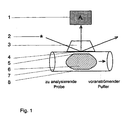
- Figure 1 shows a simplified to the most essential elements Form of a flow shear analyzer, consisting of one the sample chamber (7) similar to a flow cell, the has a circular cross-section to the direction of flow.
- the optical Unit consisting of light source (2), optically coupled Prism (3), fluorescent light analyzer (1), for conduction and Measurement of the light radiation emitted by the molecules appropriate.
- On the left is a defined on the supply side Volume unit of an immiscible fluid (6), preferably a bubble, behind the advancing buffer and before the fed to the sample to be analyzed.
- the one liquid / solid (4) and a liquid / fluid (5) boundary layer formed In such a closed flow shear analyzer system usually finds a liquid flow in the direction of the arrow, with one as needed Stagnation of flow (stopped flow) or a current reversal take place can. At the same time, the hydrostatic pressure in the chamber be increased or decreased to change the nip pressure. Furthermore, for example, by a temperature increase of Partial pressure in the air bubble to change the nip pressure be varied.
- the in the reflection point of the light beam (2) generated evanescent wave penetrates the ultrathin Liquid layer perpendicular to the flow direction down and allows the analysis of biologically active molecules depending on Boundary conditions in the liquid / solid (4) boundary layer, the liquid / fluid (5) boundary layer or in the bulk phase of ultra-thin liquid layer (8) or volatile Molecule in the gas space itself.
- FIG. 2 shows a schematic longitudinal cross section an inventive analyzer with Rheometeriki in height the axis of rotation of the rotor; and
- FIG. 3 shows the schematic structure the optical unit used.
- FIG. 2 in a longitudinal cross-section through the The rheometer unit according to the invention is shown as rotatable Rotor (1) within the schematically indicated Rotorhuntnote (2) rotatably mounted.
- the rotor touches with the top of the quartz plate (3), between the Rotor chamber side walls (2) is held tightly closed.
- the Quartz plate (3) touched, the inflow (5) and via the inflow (5) supplied liquid is via the drain (6) from the Sample chamber again actively removed by suction.
- the rotatably mounted rotor by driving the in the Drawing not shown engine act on the at the Sample chamber facing side of the quartz plate adherent Liquid film in which the in the figure 2 as black dots represented proteins (7) are contained, with increasing Speed the thickness of the liquid layer through the Shearing forces is reduced.
- injection port for the examining sample solution is optically coupled a prism (8) on the side of the quartz plate (3) facing away from the sample chamber appropriate.
- the one from the light generating unit (9), here is shown only schematically, emerging light beam is directed and excited via the prism on the adsorbed proteins to the present in the proteins tryptophan fluorophore Generation of a fluorescent light (10), the perpendicular in Direction of the prism parallel to the axis of rotation of the rotor (5) exit and in the direction of the emission monochromator with connected evaluation unit, not in Fig. 2 are shown, is conducted.
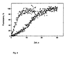
- FIG. 4 shows the comparison of the adsorption rates of fibrinogen on quartz glass, wherein an air bubble of 75 ⁇ l (closed squares) was injected in front of the solution to be investigated, or -no bubble (open triangles) was injected into a chamber of 120 ⁇ l.
- the protein concentration was 100 ⁇ g / ml
- the shear rate of the rheometer is 7200 s -1 .
- pre-injection of an air bubble decreases the adsorption half-life from 12.7 seconds (without air bubble) to 2.6 seconds (with air bubble).
- the sigmoid of the curve disappears in favor of an exponential function.
- the uncorrected 100% values were 2300 cps with and 2000 cps with bubble.
- FIG. 5 shows the exponential adsorption kinetics of fibrinogen on quartz glass, which was measured by the method of TIRF rheometry with pre-injection of an air bubble.
- the protein concentration kept constant in the flow was 188 ⁇ g / ml, the flow rate 150 ml / hr. and the shear rate of the rheometer 720 s -1 .
- the upper figure A shows the original online kinetics record.
- FIG. 6 demonstrates in the embodiment of FIG Rheometer invention, the measurement of the penetration of the evanescent light wave in and through the ultrathin Liquid layer through in the gas space of the bubble at a constant temperature of 23 ° C.
- a hydroxytryptophan standard the concentration 0.22 mM (first increase of about 200 cps at 2500 cps) is due to a bubble of a second following concentration of 0.68 mM (second increase to 5200 cps) passed separately through the measuring chamber and then through Water washed out (drop from 5200 cps to 200 cps).
- the Penetration of the evanescent wave into the bubble's airspace is due to a steep drop in fluorescence ("nose") of the level around 2500 cps just before the rise to 5200 cps visible, noticeable.
- nose a steep drop in fluorescence
- the permeated liquid film has a Layer thickness, which is smaller than 300 nm, possess.
Abstract
Description
Die vorliegende Erfindung betrifft einen Durchfluß-Scheranalysator mit Mitteln für eine rasche Durchmischung und die Erzeugung ultradünner Flüssigkeitsschichten mit den Merkmalen des Hauptanspruches zur Messung insbesondere der adsorptionsdesorptions- und reaktionskinetischen Eigenschaften von biologisch aktiven Molekülen an Oberflächen sowie Verfahren zur Bestimmung dieser Eigenschaften.The present invention relates to a flow shear analyzer with agents for rapid mixing and the Production of ultra-thin liquid layers with the characteristics of Main claim for measuring in particular the Adsorptionsdesorptions- and reaction kinetic properties of biologically active molecules on surfaces and methods for Determination of these properties.
Oberflächen treten in heterogenen Systemen auf, in denen beispielsweise mehrere Phasen mit reinen Oberflächen aneinander stoßen, wobei die einzelnen Komponenten durch eine Grenzfläche geschieden werden. Betrachtet man die grenznahe Ausdehnung einer Phase auf einer Oberfläche, so spricht man von einer Grenzschicht. Bei der Anreicherung beispielsweise von Proteinen in einer Grenzschicht an einer Oberfläche, die durch nichtkovalente Bindungskräfte bewirkt wird, spricht man von Adsorption (bei einer Abreicherung von Desorption), Vorgänge, die durch Sorptionskinetiken charakterisiert sind. In Folgereaktionen an der Oberfläche, in deren Verlauf das Protein Konformationsänderungen oder Strukturänderungen (Primärstruktur) durchmachen kann, Bindungen mit Liganden eingeht oder aber kovalente Bindungen mit der Oberfläche geknüpft werden - Vorgänge, die durch Reaktionskinetiken charakterisiert sind - findet die Adsorptionsreaktion häufig ihren Abschluß.Surfaces occur in heterogeneous systems in which For example, several phases with pure surfaces together butt, with the individual components passing through an interface be divorced. Looking at the borderline extension a phase on a surface, this is called a Boundary layer. In the enrichment of, for example, proteins in a boundary layer on a surface by noncovalent Binding forces is effected, one speaks of Adsorption (at a depletion of desorption), processes, characterized by sorption kinetics. In follow-up reactions on the surface, in the course of which the protein Conformational changes or structural changes (primary structure) can undergo or bind with ligands but covalent bonds are made with the surface - processes characterized by reaction kinetics - the adsorption reaction often comes to an end.
Das Verhalten von biologisch bedeutsamen Molekülen, beispielsweise von Proteinmolekülen, an Oberflächen ist wichtig bei der Beurteilung von Vorgängen in der Biologie, der Biochemie, beim Einsatz von Biosensoren und bei der Beurteilung von biomedizinischen Materialien. Dabei sind die Eigenschaften der Oberflächen bei chromatographischen Verfahren, bei Biosensoren und die Biokompatibilität der Implantate von der Bindungsfähigkeit der Proteine und ihrer Liganden an die Oberfläche abhängig. Bei Biosensoren kann aus der Bindung von Proteohormonen an besonderen Oberflächen auf die Hormonkonzentration im Blut geschlossen werden, bei Implantaten dagegen kann die Ablagerung von Plasmaproteinen an dem Fremdmaterial zur Entstehung von Thrombosen und der Aktivierung des Komplements führen.The behavior of biologically important molecules, For example, from protein molecules to surfaces is important in the evaluation of events in biology, the Biochemistry, the use of biosensors and in the assessment of biomedical materials. Here are the properties the surfaces in chromatographic processes, at Biosensors and the biocompatibility of the implants of the Binding ability of the proteins and their ligands to the Surface dependent. For biosensors, the binding of Proteohormones on special surfaces on the hormone concentration be closed in the blood, with implants on the other hand may be the deposition of plasma proteins on the foreign material on the development of thrombosis and the activation of the Complements lead.
Für die direkten Online-Messungen der Wechselwirkung von Proteinen und deren Liganden mit Oberflächen wird im Stand der Technik beispielsweise die Oberflächen-Plasmonresonanz, die Interferometrie, die Ellipsometrie, die Reflektometrie oder bevorzugt die totale interne Reflektionsfluoreszenz-Technik ("total internal reflection fluorescence" - TIRF) verwendet, bei der ausgenutzt wird, daß ein einfallender Lichtstrahl an einer Grenzschicht zwischen einem optisch dichteren Medium (beispielsweise ein Feststoff) und einem optisch dünneren Medium (beispielsweise einer Flüssigkeit) total reflektiert wird, wenn der Einfallswinkel größer als der kritische Winkel für das optisch dichtere Medium ist. Am Reflektionspunkt im optisch dichteren Medium tritt eine senkrecht zur Oberfläche des dichteren Mediums stehende Welle der gleichen Frequenz wie die Frequenz des einfallenden Lichtes auf (sog. evaneszente Welle), die sich in das dünnere Medium ausbreitet. Die Amplitude der evaneszenten Welle nimmt dabei exponentiell im optisch dünneren Medium ab. Die Durchdringungstiefe dieser in die Untersuchungslösung austretenden evaneszenten Welle ist abhängig von der Wellenlänge und im allgemeinen geringer als 200-300 nm, jedoch ausreichend tief, um Fluorophore in der Nähe der Grenzfläche anzuregen, wobei eine Anregung des größten Teils der in der Lösung (Bulklösung) befindlichen Proteine vermieden wird.For direct online measurements of the interaction of Proteins and their ligands with surfaces is in the state of Technique, for example, the surface plasmon resonance, the Interferometry, ellipsometry, reflectometry or prefers the total internal reflection fluorescence technique ("totally internal reflection fluorescence" - TIRF), exploited in that an incident light beam on a boundary layer between a more dense medium (For example, a solid) and an optically thinner Medium (for example, a liquid) totally reflected when the angle of incidence is greater than the critical angle for the optically denser medium. At the reflection point in the optically denser medium occurs perpendicular to the surface the denser medium standing wave of the same frequency as the frequency of the incident light (so-called evanescent Wave), which spreads into the thinner medium. The Amplitude of the evanescent wave increases exponentially optically thinner medium from. The penetration depth of this in the investigative solution is exiting evanescent wave depending on the wavelength and generally less than 200-300 nm, but sufficiently deep, to near fluorophores to stimulate the interface, with an excitation of the largest Part of the proteins in the solution (Bulk solution) is avoided.
Bei Verwendung einer Anregungswellenlänge von 290 nm ist es möglich, den Tryptophanchromophor in einem Protein selektiv anzuregen, der ein Fluoreszenzmaximum bei 350 nm besitzt. Anderseits ist es auch möglich, über chemische Modifikation einen zusätzlichen Fluorophor in das Protein einzubringen, wobei jedoch die Gefahr der konformationellen Änderungen der Struktur des Proteins besteht.It is when using an excitation wavelength of 290 nm possible, the tryptophan chromophore in a protein selectively to excite, which has a fluorescence maximum at 350 nm. On the other hand, it is also possible via chemical modification to introduce an additional fluorophore into the protein, however, the danger of conformational changes in the Structure of the protein exists.
Nach der Durchmischung der Probe in der Probenkammer hängt die gemessene Adsorptionsrate des Proteins an der Oberfläche ohne oder bei nur geringer Strömung von drei unterschiedlichen Schritten ab: 1. dem Massentransport des Proteins in die zwischen Flüssigkeit und Festkörperoberfläche ausgebildete Grenzschicht, 2. der intrinsischen Bindungsgeschwindigkeit und 3. der intrinsischen Dissoziationsgeschwindigkeit. Wenn die Bindungsgeschwindigkeit sehr niedrig ist, wie es bei z.B. sehr niedrigen Oberflächenkonzentrationen der Bindungsstellen für das Protein am Feststoff der Fall ist, wird keine Verarmung an Protein in der Grenzschicht auftreten, und die Adsorptionsgeschwindigkeit wird nur von der intrinsischen Bindungsgeschwindigkeit abhängen.After mixing the sample in the sample chamber hangs the measured adsorption rate of the protein on the surface without or at low flow of three different ones Steps from: 1. the mass transport of the protein into the formed between liquid and solid surface Boundary layer, 2. the intrinsic binding rate and 3. the intrinsic dissociation rate. If the Binding rate is very low, as it is at e.g. very low surface concentrations of the binding sites for the protein on the solid does not become depleted Protein occur in the boundary layer, and the Adsorption rate is only from the intrinsic Depend on bond speed.
In vielen Fällen ist jedoch die Bindungsgeschwindigkeit höher als die Transportgeschwindigkeit, so daß die Diffusion nicht ausreichend ist, die Konzentration an Protein in der Grenzschicht auf einem bestimmten Niveau zu halten, was die Gesamtreaktion von dem Massentransport abhängig macht. Das bedeutet, daß die Adsorptionsrate beispielsweise stark vom Rühren abhängig ist.In many cases, however, the binding rate is higher as the transport speed, so that the diffusion is not is sufficient, the concentration of protein in the Keep the boundary layer at a certain level, which is the Overall reaction depends on the mass transport. The means that the adsorption rate, for example, strongly from Stirring is dependent.
Es tritt auch der Fall ein, daß die Durchmischungsgeschwindigkeit der Probe im Aufnahmevolumen der Probenkammer kleiner ist als die Transportgeschwindigkeit oder die Bindungsgeschwindigkeit, und daß sie somit geschwindigkeitsbestimmend für die Adsorptionsrate des Proteins wird. Eine einfache Lösung für die Reduktion der bei 2-8 s liegenden Durchmischungszeiten in Probenkammern von 100-200 µl Volumen wurde im dem Stand der Technik bisher nicht gefunden.There is also the case that the mixing speed the sample in the volume of the sample chamber is less than the transport speed or the Binding speed, and thus that they are rate-limiting for the adsorption rate of the protein. A simple solution for the reduction of 2-8 s lying Mixing times in sample chambers of 100-200 μl volume has not been found in the prior art.
Im Stand der Technik wurden einige Lösungsansätze zum Messen der adsorptionskinetischen Daten veröffentlicht, die versuchen, dem Massentransport Rechnung zu tragen. Der Massentransportkoeffizient (Km), der als Km = D/d (D = Diffusionskonstante, d = Schichtdicke) definiert ist, liegt bei einer nicht gerührten Schichtdicke von 10 µm beispielsweise für Fibrinogen bestenfalls bei 2 x 10⁻⁶ m/s und führt zu einer deutlichen Transportlimitierung. Wenn man jedoch ein direktes kinetisches Signal ohne den störenden Einfluß des Massentransportes erhalten will, muß man die Dicke der nicht gerührten Schichtdicke reduzieren und dies in einem solchen Ausmaß, daß die Adsorptionsrate unabhängig von dem Massentransport durch die Schicht wird. Für das letztgenannte Problem sind im Stand der Technik bis jetzt keine Lösungen vorgeschlagen worden.Some approaches have been published in the prior art for measuring adsorption kinetic data which attempt to account for mass transport. The mass transfer coefficient (Km), which is defined as Km = D / d (D = diffusion constant, d = layer thickness), for a fibrinogen at a non-stirred layer thickness of 10 μm, is at best 2 × 10 -6 m / s and leads to a clear transport limitation. However, if one wishes to obtain a direct kinetic signal without the interfering influence of mass transport, one must reduce the thickness of the unmilled layer thickness and to such an extent that the adsorption rate becomes independent of the mass transport through the layer. For the latter problem, no solutions have heretofore been proposed in the prior art.
Die Aufgabe der Erfindung besteht nun darin, ein Meßsystem und Meßverfahren bereitzustellen, mit dem adsorptions-, desorptions- oder reaktionskinetische Meßwerte für biologisch aktive Moleküle ohne den störenden Einfluß sowohl der Durchmischung als auch des Massentransports gemessen werden können.The object of the invention is now a measuring system and Provide a measuring method with the adsorption, desorption or reaction kinetic measurements for biological active molecules without the disturbing influence of both Mixing and the mass transport are measured can.
Seitens der Erfinder wurde nun überraschend gefunden, daß diese
Aufgaben gelöst werden durch Bereitstellung (1) eines
Durchfluß-Scheranalysators gemäß dem Anspruch 1. The inventors have now surprisingly found that these
Problems to be solved by providing (1) one
Flow shear analyzer according to
Mit Hilfe des erfindungsgemäßen Analysators ist es nach kürzester Durchmischung möglich, in einer extrem dünnen Schichtdicke die Sorptions- und Reaktionsgeschwindigkeitskonstanten von biologischen aktiven Molekülen wie Proteinen und deren Liganden gegenüber Oberflächen zu bestimmen, wobei die Oberflächen mit verschiedensten anorganischen, organischen oder biologischen Molekülen oder Materialien mit Hilfe von chemischen oder physikalischen Verfahren oder einer Kombinationen dieser Verfahren modifiziert oder beschichtet sein können, um die Adsorptions- Desorptions- oder Reaktionscharakteristika der biologisch aktiven Moleküle in Bezug auf Affinität oder Spezifität der Bindung zu steuern.With the help of the analyzer according to the invention it is after shortest mixing possible, in an extremely thin Layer thickness the sorption and reaction rate constants of biologically active molecules such as proteins and their ligands to determine surfaces, the Surfaces with a variety of inorganic, organic or biological molecules or materials with the help of chemical or physical process or one Combinations of these methods modified or coated can be to the adsorption desorption or Reaction characteristics of the biologically active molecules in Terms of affinity or specificity of binding.
Unter biologisch aktiven Molekülen wird erfindungsgemäß jede Art von Molekülen einschließlich monomerer oder polymerer Biomoleküle sowie deren Liganden verstanden, die in irgendeiner Weise eine biologische Aktivität entfalten. So kann es sich bei den biologisch aktiven Verbindungen beispielsweise um Proteine, Pharmazeutika oder andere in irgendeiner Weise in einem Biosystem wirksame chemische oder biochemische Verbindungen handeln. Entscheidend ist allerdings, daß die Verbindungen in jedem Fall auf der Oberfläche oder in der Grenzfläche durch signalgebende Eigenschaften einer Detektion zugänglich sind. Dies kann der Fall sein beispielsweise durch hervorgerufene Veränderungen in der Oberflächen-Plasmonresonanz, des Oberflächeninterferenzspektrums, des Brechungsindexes, der Oberflächenreflektion, der Drehung der Polarisationsebene des Lichtes, oder vorzugsweise durch Veränderungen in der von den Molekülen ausgehenden Strahlung, die beispielsweise durch Anregung eines im Molekül vorhandenen Chromophors beispielsweise mit Licht oder durch Markierung des biologisch aktiven Moleküls mit einem radioaktiven Isotop erzeugt wird. Dabei sollten durch Markieren oder Einbringen beispielsweise eines Chromophors in das biologisch aktive Molekül die Adsorptionscharakteristika möglichst unverändert gegenüber dem nicht markierten Zustand bleiben.According to the invention, biologically active molecules are any Type of molecules including monomeric or polymeric Biomolecules and their ligands understood in any Way to develop a biological activity. That is how it can be the biologically active compounds, for example proteins, Pharmaceuticals or others in one way or another Biosystem effective chemical or biochemical compounds act. However, it is crucial that the compounds in in any case on the surface or in the interface Signaling properties of a detection are accessible. This may be the case, for example, caused by Changes in surface plasmon resonance, the Surface interference spectrum, the refractive index, the Surface reflection, the rotation of the polarization plane of the Light, or preferably by changes in the of the Molecules emit radiation, for example, through Excitation of a chromophore present in the molecule for example, with light or by marking the biological active molecule is generated with a radioactive isotope. It should by marking or inserting example a chromophore into the biologically active molecule the Adsorption characteristics as unchanged as possible over the remain unmarked state.
Falls bevorzugt zur Analyse der von den biologisch aktiven Molekülen emittierten Strahlung das TIRF-Verfahren erfindungsgemäß verwendet wird, weist die Strahlungsanalyseeinheit z.B. eine optische Einheit aus einer Lichtquelle, die einen monochromatischen Lichtstrahl liefert, einen Strahlungsleiter, z.B. ein optisches Prisma und einen Strahlungsanalysator, z.B. einen Emissionsmonochromator mit angeschlossener Auswertungseinheit auf, wobei das Prisma und die Lichtquelle derart zueinander angeordnet sind, daß der aus der Lichtquelle austretende Lichtstrahl über das auf der lichtdurchlässigen Quarzplatte optisch gekoppelt angeordnete Prisma in einem Winkel der größer als der kritische Winkel für das dichtere Medium ist, auf die Grenzschicht zwischen Quarzplatte und Lösung auftrifft, und das gebildete Fluoreszenzlicht, das an der Grenzschicht zwischen Quarzplatte und Probenflüssigkeit in der Probenkammer erzeugt wird und im wesentlichen lotrecht zur Oberfläche der Quarzplatte austritt, über ein optisches System in den Emissionsmonochromator geleitet wird.If preferred for analysis of the biologically active Molecules emitted radiation the TIRF method used in the invention, the radiation analysis unit e.g. an optical unit of a light source, the provides a monochromatic light beam, a Radiation conductor, e.g. an optical prism and a Radiation analyzer, e.g. an emission monochromator with connected evaluation unit, wherein the prism and the light source are arranged to each other such that the the light source exiting light beam over the on the translucent quartz plate optically coupled Prism at an angle greater than the critical angle for the denser medium is, on the boundary layer between Quartz plate and solution impinges, and the formed Fluorescent light at the interface between quartz plate and sample liquid is generated in the sample chamber and in the essentially perpendicular to the surface of the quartz plate, via an optical system into the emission monochromator is directed.
Um die gewünschte dünne Schichtdicke zu erzielen, sind erfindungsgemäß Mittel zur Erzeugung von Scherkräften und Spaltdrucken vorgesehen, die im Inneren der Probenkammer auf die Oberfläche der Quarzplatte wirken. Dabei können diese Scherkräfte erfindungsgemäß mechanisch erzeugt werden. Im einfachsten Fall können die Scherkräfte durch einen Volumenstrom durch die Kammer oder aber durch die Drehung eines zylindrischen Rotors in unmittelbarer Nähe zur Meßfläche erzeugt werden. Auf diese Weise erzeugte Scherraten liegen beispielsweise in der Größenordnung von 104 - 105 s-1, führen zu Flüssigkeitsschichten von 5-15 µm Dicke und fördern den Einsatz der erfindungsgemäßen Mittel zur Erzeugung ultradünner Schichten sowie der Fortbewegung der erzeugten Schichten.In order to achieve the desired thin layer thickness, means for generating shear forces and nip pressures are provided according to the invention, which act on the surface of the quartz plate in the interior of the sample chamber. These shear forces can be generated mechanically according to the invention. In the simplest case, the shear forces can be generated by a volume flow through the chamber or by the rotation of a cylindrical rotor in close proximity to the measuring surface. Shear rates generated in this way are for example in the order of 10 4 - 10 5 s -1 , lead to liquid layers of 5-15 microns thick and promote the use of the inventive means for producing ultra-thin layers and the movement of the layers produced.
Die entscheidende Verringerung der Schichtdicke unter 5 µm wird erfindungsgemäß dadurch möglich, daß mittels einer zuleitungsseitig angeordneten Vorrichtung Volumeneinheiten in der Größenordnung von 10-100%, vorzugsweise 50-75%, des Kammervolumens aus einem mit der Kammerlösung nicht mischbaren Fluid in Volumenstromsegmente mit vorzugsweise gleichem Volumen in die Kammerlösung zugespeist werden, die als Mittel dienen, das Flüssigkeitsvolumen in der Meßzelle und die Flüssigkeitsschicht auf der Meßfläche extrem zu reduzieren. Bei der Kammerlösung kann es sich um eine hydrophile, wäßrige oder aber auch um eine hydrophobe, organische Flüssigkeit handeln, wobei das nicht mischbare Fluid so beschaffen ist, das es im ersten Fall nicht mit der hydrophilen und im zweiten Fall nicht mit der hydrophoben Flüssigkeit mischbar ist. Vorzugsweise handelt es sich bei der Kammerlösung um eine Pufferlösung hydrophiler, wäßriger Art. Vorzugsweise erfolgt die Anordnung so, daß eine Volumeneinheit des vorgenannten Fluids direkt vor der Zugabe einer Analysenlösung in die durch die Probenkammer geleitete Pufferlösung eingebracht wird und so durch Verdrängung des Flüssigkeitsvolumens das wirksame Kammervolumen und somit die Durchmischungszeit reduziert, die Probenkammer freispült, und der Spaltdruck zwischen Fluid und Probenkammerwand dabei eine extrem dünne Flüssigkeitsschicht zwischen 10 und 300 nm erzeugt, die keine meßbare Transportbarriere mehr darstellt, da sich der Massentransportkoeffizient beispielsweise für Fibrinogen um mehrere Größenordnungen auf 10-4 bis 10-2 m/s erhöht. The decisive reduction of the layer thickness below 5 microns is inventively possible by means of a supply side arranged volume units in the order of 10-100%, preferably 50-75% of the chamber volume from a non-miscible with the chamber solution fluid in volume flow segments with preferably the same Volumes are fed into the chamber solution, which serve as a means to extremely reduce the volume of liquid in the measuring cell and the liquid layer on the measuring surface. The chamber solution may be a hydrophilic, aqueous or even a hydrophobic organic liquid, the immiscible fluid being such that it is immiscible with the hydrophilic liquid in the first case and not with the hydrophobic liquid in the second case is. The chamber solution is preferably a buffer solution of a hydrophilic, aqueous type. The arrangement is preferably such that a volume unit of the aforementioned fluid is introduced into the buffer solution passed through the sample chamber immediately before the addition of an analysis solution and thus the effective volume is removed by displacement of the liquid volume chamber volume and thus the mixing time is reduced, flushes the sample chamber, and the nip pressure between the fluid and the sample chamber wall thereby an extremely thin liquid layer between 10 and 300 nm produced which no measurable transport barrier more is because the mass transfer coefficient, for example, fibrinogen several orders of magnitude at 10 - 4 to 10 -2 m / s increased.
Bei dem in die Pufferlösung eingebrachten Fluid kann es sich beispielsweise um ein Gas oder eine mit der Pufferlösung nicht mischbare Flüssigkeit handeln. Bevorzugt ist die Verwendung von Gas, im einfachsten Fall von Luft. Bei der Verwendung von Gas als nicht mischbarem Fluid kann eine einzelne Gasblase bei Einbringen in die Zuführung je nach Strömungsbedingungen in der Zuleitung in eine Reihe von kleineren Gasblasen nach Art einer "Perlenschnur" zerrissen werden. Ferner ist es bei der Verwendung von Gas als nicht mischbarem Fluid auch möglich, die Schichtdicke zwischen Gasblase und Probenkammerwand in der Probenkammer dadurch zu verringern, daß der Druck unter dem das Gas in die Zuleitung eingebracht wird, erhöht wird. Dabei wird der erfindungsgemäße Durchfluß-Scheranalysator bevorzugt als ein geschlossenes System ausgebildet, d.h. im Leitungssystem des Analysators wird ein gegenüber dem Außendruck erhöhter Druck aufrecht erhalten.The fluid introduced into the buffer solution may be for example, a gas or not with the buffer solution act mixable liquid. Preference is given to the use of Gas, in the simplest case of air. When using gas a non-miscible fluid may be a single gas bubble Introduce into the feeder depending on the flow conditions in the Feed into a series of smaller gas bubbles in the manner of a "String of pearls" to be torn. Furthermore, it is at the Use of gas as immiscible fluid also possible, the Layer thickness between gas bubble and sample chamber wall in the To reduce sample chamber by the fact that the pressure under the Gas is introduced into the supply line is increased. It will the flow shear analyzer according to the invention is preferred as a closed system is formed, i. in the pipe system of the analyzer is increased compared to the external pressure Maintained pressure.
Die Zuführung des Fluids zuleitungsseitig in die Zuleitung für die Pufferlösung kann beispielsweise über ein Zweiwegeventil erfolgen, das jeweils einen Anschluß für die Zuführung der Pufferlösung und das Fluid sowie eine Abführung des gebildeten Volumenstromes zur Probenkammer aufweist. Die Zuführung des Fluids kann kontinuierlich oder diskontinuierlich erfolgen, wobei bei letzterer Möglichkeit z.B. über die Stellung des Zweiwegeventils zwischen der Zuleitung der Pufferlösung und des Fluids hin und her geschaltet wird.The supply of the fluid supply side in the supply line for the buffer solution may be, for example, via a two-way valve take place, each having a connection for the supply of the Buffer solution and the fluid and a discharge of the formed Volume flow to the sample chamber has. The feeder of the Fluids can be continuous or discontinuous, the latter possibility being e.g. on the position of Two-way valve between the supply of the buffer solution and the Fluids is switched back and forth.
In der einfachsten Ausführung des Scheranalysators handelt es sich um ein geschlossenes System und bei der Probenkammer um eine Durchflußküvette mit einem senkrecht zur Flußrichtung rechteckigen oder kreisförmigen Querschnitt, die beispielsweise in einen Probenkammerblock eingesetzt ist und an deren Wandabschnitt die Strahlungsanalyseeinheit, z.B. die optische Einheit zur Leitung und Messung der von den Molekülen emittierten Strahlung angeordnet ist. Bei einem Kammervolumen von 100-200 µl kann das Durchflußvolumen Werte von 1-1000 ml/Std., vorzugsweise 150-200 ml/Std. annehmen, wobei Scherraten bis zu einer Größenordnung von 104 s-1 oder darüber entstehen können. Zuleitungsseitig wird eine definierte Volumeneinheit eines nicht mischbaren Fluids vor der zu analysierenden Probe zugespeist als Mittel zur Reduktion der Flüssigkeit in der Kammer und somit der Durchmischungszeit, insbesondere aber zur Erzeugung einer extrem dünnen Flüssigkeitsschicht. Bevorzugt ist eine kontinuierliche Durchströmung unter Erzeugung einer konstanten Scherrate (vorzugsweise 500-1000 s-1) in einer Richtung, unter Bewegung der ultradünnen Flüssigkeitsschicht durch den Flüssigkeitsstrom in den TIRF-Meßbereich hinein, wobei die Temperatur konstant zu halten ist. Die biologisch aktiven Moleküle werden im Bereich der fest/flüssig Grenzfläche an der Quarzglaswand der Probenkammer adsorbiert und durch die optische Einheit am Analysator detektiert.The simplest embodiment of the shear analyzer is a closed system and the sample chamber is a flow cell having a rectangular or circular cross-section perpendicular to the flow direction, for example inserted in a sample chamber block and at its wall portion the radiation analysis unit, eg the optical unit for conduction and measuring the radiation emitted by the molecules. With a chamber volume of 100-200 μl, the flow volume can be 1-1000 ml / hr, preferably 150-200 ml / hr. assuming that shear rates up to or above 10 4 s -1 can occur. On the supply side, a defined volume unit of an immiscible fluid is fed in front of the sample to be analyzed as a means for reducing the liquid in the chamber and thus the mixing time, but in particular for producing an extremely thin liquid layer. Preferably, a continuous flow is provided to produce a constant shear rate (preferably 500-1000 s -1 ) in one direction, while moving the ultra-thin liquid layer through the liquid flow into the TIRF measurement range while maintaining the temperature constant. The biologically active molecules are adsorbed in the region of the solid / liquid interface on the quartz glass wall of the sample chamber and detected by the optical unit on the analyzer.
Sollen sehr schnelle relaxationskinetische Experimente durchgeführt werden, wird bei hoher Durchflußgeschwindigkeit eine Volumeneinheit des nicht mischbaren Fluids vor der Analysenlösung in einem kontinuierlichen Strom in die Probenkammer geleitet. Befindet sich das nicht mischbare Fluidvolumen und somit die extrem dünne Flüssigkeitsschicht vorzugsweise im Bereich des Meßfeldes, wird der Flüssigkeitsstrom augenblicklich angehalten (sog. "stopped flow" oder "stopped-flow concentration jump" Methode), damit die Wechselwirkung des biologisch aktiven Moleküls mit der Oberfläche in Abwesenheit von Scherkräften an einer definierten Stelle der Quarzglaswand vom optischen System aufgenommen werden kann. Im Verlauf eines solchen Experimentes kann es notwendig werden, den Flüssigkeitsstrom in seiner Richtung umzukehren, um beispielsweise im selben Experiment andere Bereiche der extrem dünnen Flüssigkeitsschicht, der Grenzschichten oder der Fluidphase zusätzlich oder bei einer anderen Temperatur einer Messung zuzuführen. Auch läßt sich die Temperatur im Stromstillstand sprunghaft verändern, um "stopped-flow temperature jump" Experimente durchzuführen. Are very fast relaxation kinetic experiments be carried out at high flow rate a volume unit of the immiscible fluid before Analysis solution in a continuous stream in the Passed sample chamber. Is the immiscible Fluid volume and thus the extremely thin liquid layer preferably in the region of the measuring field, the liquid flow stopped immediately (so-called "stopped flow" or "stopped-flow concentration jump" method), so that the Interaction of the biologically active molecule with the Surface in the absence of shear forces on a defined Position of the quartz glass wall taken by the optical system can be. In the course of such an experiment it can become necessary, the liquid flow in his direction to reverse, for example, in the same experiment others Areas of the extremely thin liquid layer, the Boundary layers or the fluid phase additionally or at a to supply another temperature to a measurement. Also, can the Rapidly change the temperature during standstill to "stopped-flow temperature jump" experiments.
In dem erfindungsgemäßen Durchfluß-Scheranalysator können sich die biologisch aktiven Moleküle nach der Zuführung des nicht mischbaren Fluids in vier Bereichen befinden: (1) in der fest/flüssig Grenzschicht, (2) in der flüssig/Fluid Grenzschicht, (3) in der Flüssigkeitsbulkphase oder (4) der Fluidbulkphase. Im Bereich der durch das vorgenannte Fluid erzeugten ultradünnen Flüssigkeitsschicht sind bei hinreichender Eindringtiefe der evaneszenten Welle Konzentrationsveränderungen der biologisch aktiven Moleküle in allen vier Bereichen einer Messung zugänglich.In the flow shear analyzer according to the invention may the biologically active molecules after delivery of not Miscible fluids are located in four areas: (1) in the solid / liquid boundary layer, (2) in the liquid / fluid Boundary layer, (3) in the liquid bulking phase or (4) the Fluidbulkphase. In the area through the aforementioned fluid produced ultra-thin liquid layer are at sufficient penetration depth of the evanescent wave Concentration changes of the biologically active molecules in accessible to all four areas of a measurement.
In einer anderen bevorzugten Ausführungsform, eines offenen Systems, ist der erfindungsgemäße Analysator derart ausgestaltet, daß weitere Mittel zur Erzeugung der extrem dünnen Flüssgkeitsschichten dadurch ausgebildet sind, daß die Probenkammer in Form einer zylindrischen Rheometerkammer zur Aufnahme von Analyse- bzw. Pufferlösung ausgebildet ist, deren eines Ende von einer lichtdurchlässigen Quarzplatte dicht verschlossen ist, in der ein zylinderförmiger Rotor, bevorzugt aus einem lichtdurchlässigen Material, drehbar gelagert ist, dessen Außendurchmesser dem Innendurchmesser der Rheometerkammer angepaßt ist, wobei der zylindrische Rotor an der, der Quarzplatte zugewandten Seite kegelförmig ausgebildet ist und die Quarzplatte mit der in der Drehachse des Rotors liegenden Kegelspitze berührt; und die eine Zuleitung und eine Ableitung für die Pufferlösung in die aus Rheometerkammerinnenwänden, Rotorkegel und lichtdurchlässiger Quarzplatte gebildeter Probenkammer, aufweist, und ein Motor zum Antrieb des Rotors vorgesehen ist.In another preferred embodiment, an open one Systems, the analyzer according to the invention is such designed that further means of producing the extremely thin Liquid layers are formed in that the Sample chamber in the form of a cylindrical Rheometerkammer for Recording of analysis or buffer solution is designed, whose one end of a translucent quartz plate tight is closed, in which a cylindrical rotor, preferably made of a translucent material, is rotatably mounted, the outer diameter of the inner diameter of Rheometerkammer adapted, wherein the cylindrical rotor to the, the quartz plate facing side cone-shaped is and the quartz plate with the in the axis of rotation of the rotor touching the tip of the cone; and the one supply line and one Discharge for the buffer solution in the out Rheometer chamber interior walls, rotor cones and translucent Quartz plate formed sample chamber, and a motor is provided for driving the rotor.
Diese Ausführungsform des erfindungsgemäßen Analysators besitzt dabei als wesentliche Bestandteile die Analysatoreinheit und die optische Einheit, die an die Analysatoreinheit gekoppelt ist. Die Analysatoreinheit weist dabei einen Kammerblock mit einer darin befindlichen zylindrischen Rheometerkammer auf, in der ein Rotor aus einem lichtdurchlässigen Material wie beispielsweise Polymethylmethacrylat drehbar gelagert ist, wobei der Außendurchmesser des Rotors dem Innendurchmesser der zylindrischen Analysatorkammer angepaßt ist.This embodiment of the analyzer according to the invention has as essential components, the analyzer unit and the optical unit coupled to the analyzer unit is. The analyzer unit has a chamber block with it a cylindrical Rheometerkammer located therein, in a rotor made of a translucent material such as For example, polymethyl methacrylate is rotatably mounted, wherein the outer diameter of the rotor is the inner diameter of adapted cylindrical analyzer chamber.
Das Ende der Analysatorkammer ist von einer lichtdurchlässigen festen Platte, z.B. einer Quarzglasplatte, deren Oberfläche chemisch oder physikalisch modifiziert sein kann, verschlossen, wobei der Rotor an der lichtdurchlässigen Quarzplatte zugewandten Seite kegelförmig ausgebildet ist, und der Rotor mit der Kegelspitze die lichtdurchlässige Quarzplatte berührt und die eigentliche Analysatorkammer bildet. Der Winkel in der Kegelspitze zur Drehachse (Kegelschräge/Drehachse) beträgt dabei etwa 85° bis 89.9°, vorzugsweise 89°, so daß eine Probenkammer mit einem um die Drehachse des Rotors vorhandenen dreieckigen Radialquerschnitt gebildet wird, wobei der Dreieckswinkel an der Kegelspitze etwa 0.1° bis 5°, vorzugsweise 1°, beträgt.The end of the analyzer chamber is of a translucent fixed plate, e.g. a quartz glass plate whose surface chemically or physically modified, sealed, the rotor being attached to the translucent quartz plate facing side is conical, and the rotor touch the translucent quartz plate with the cone tip and the actual analyzer chamber forms. The angle in the Cone tip to the axis of rotation (taper slope / axis of rotation) amounts while about 85 ° to 89.9 °, preferably 89 °, so that a Sample chamber with an existing around the axis of rotation of the rotor triangular radial cross section is formed, wherein the Triangle angle at the apex about 0.1 ° to 5 °, preferably 1 °.
Der Durchmesser der Rheometerkammer bzw. des Rotors, im allgemeinen etwa 2-4 cm, ist dabei so aufeinander in Abhängigkeit von dem zuvor genannten Dreieckswinkel bestimmt, daß sich ein Probenkammervolumen von 10 bis zu 1000 µl, vorzugsweise 50 bis 150, besonders bevorzugt 100-120 µl ergibt. In die Probenkammer wird eine Pufferlösung über eine Zuleitung ein- und über eine Ableitung abgeleitet, die bevorzugt in der Quarzplatte angeordnet sind. Durch den sich drehenden Konus wird auf der Quarzplatte, auf der das Protein adsorbiert werden soll, ein Scherkraftfeld zur Erzeugung von Scherraten über die in der Probenkammer befindliche Pufferlösung erzeugt, und es ist entsprechend nach Einbringung der zu untersuchenden, das Protein enthaltenden Lösung möglich, die Adsorption des Proteins an die Oberfläche in Abhängigkeit von der Drehzahl des Rotors zu untersuchen.The diameter of the Rheometerkammer or the rotor, im general about 2-4 cm, is doing so in succession Depending on the aforementioned triangular angle, that a sample chamber volume of 10 to 1000 ul, preferably 50 to 150, more preferably 100-120 ul results. In the sample chamber is a buffer solution via a supply line derived and derived via a derivative, which is preferred in the Quartz plate are arranged. Through the rotating cone will be on the quartz plate on which the protein is adsorbed is supposed to be a shear force field for generating shear rates over the produced in the sample chamber buffer solution, and it is accordingly after introduction of the examined, the Protein-containing solution possible, the adsorption of the Protein to the surface depending on the speed of the To investigate rotor.
Dabei ist die Kammer bevorzugt so ausgebildet, daß gleichzeitig, d.h. bei Drehung des Rotors, das Durchflußvolumen (Kammer mit 1° -Winkel) eine Größe zwischen 1 bis 500 ml pro Stunde, vorzugsweise 150 ml/Std., einnehmen kann. Dieser Volumendurchstrom erzeugt zusätzlich eine signifikante Scherrate in einer Größenordnung bis zu 104 s-1, so daß ein System entsteht, bei dem die Gesamtscherrate als Summe aus der Scherrate des Durchflusses und der Scherrate der Kegelrotation betrachtet werden kann.The chamber is preferably designed so that at the same time, ie upon rotation of the rotor, the flow volume (chamber with 1 ° angle) a size between 1 to 500 ml per hour, preferably 150 ml / hr, can take. In addition, this volumetric flow rate produces a significant shear rate of up to 10 4 s -1 , thus creating a system in which the total shear rate can be considered as the sum of the shear rate of the flow and the shear rate of the cone rotation.
Mit Hilfe der erfindungsgemäßen Vorrichtung und des unter Verwendung der Vorrichtung angewandten Verfahrens ist es möglich, die Proteinadsorption in der fest/flüssig Grenzschicht an der Quarzglasplatte unter genau definierten externen Scherkräften und Schichtdicken zu bestimmen. Die Vorrichtung kann auch verwendet werden, um beispielsweise die Scherbedingungen im Blutstrom in vivo während der Proteinabsorption zu simulieren, und die durch den Fluß induzierte Scherung bei adsorptionschromatographischen Säulen für Proteintrennungen zu analysieren.With the help of the device according to the invention and the under It is the use of the device method possible, the protein adsorption in the solid / liquid boundary layer on the quartz glass plate under well-defined external Shear forces and layer thicknesses to determine. The device can also be used to, for example, the Shearing conditions in the bloodstream in vivo during the To simulate protein absorption, and by the flow Induced shear in adsorption chromatographic columns to analyze for protein separations.
In einer bevorzugten Ausführungsform sind die Zuleitung und die Ableitung der Pufferlösung in die Probenkammer in einer Linie mit der Kegelspitze auf der Quarzplatte angeordnet, und weiter bevorzugt ist die Zuleitung in der Nähe der Kegelspitze angeordnet. So kann die Untersuchungslösung an der Stelle der Probenkammer eingebracht werden, an der diese die geringste axiale Ausdehnung besitzt (damit die zu durchdringende Schicht bei der Adsorption der Proteine an die ggf. modifizierte Oberfläche der Quarzplatte eine möglichst geringe Dicke aufweist), und so ist eine möglichst geringe Schichtdicke zur Adsorption der Proteine an die ggf. modifizierte Quarzplatte von den Proteinen zu durchdringen.In a preferred embodiment, the supply line and the Derive the buffer solution into the sample chamber in a line with the cone tip arranged on the quartz plate, and on Preferably, the supply line is near the apex of the cone arranged. Thus, the investigation solution at the point of Sample chamber are introduced at this the smallest axial extent possesses (thus the layer to be penetrated in the adsorption of the proteins to the optionally modified Surface of the quartz plate as small as possible thickness has), and so the smallest possible layer thickness for Adsorption of the proteins to the optionally modified quartz plate to penetrate from the proteins.
Bevorzugt befindet sich die Injektionsöffnung zur Einbringung der Probenlösung in der Zuleitung der Pufferlösung in die Probenkammer, besonders bevorzugt in der Zuleitung in der Nähe der Quarzplatte an der Stelle, wo Quarzplatte und Zuleitung miteinander verbunden sind. Bei Einbringen der Probenlösung, die die zu untersuchenden Proteine enthält, bevorzugt in der Nähe der Drehachse des Rotors, über die Injektionsöffnung mittels einer Pumpe und Zuleitung in die Probenkammer wird die Probenlösung durch die Pufferlösung verdünnt radial und tangential nach außen bewegt und die in der Lösung enthaltenen Proteine kommen dabei mit der ggf. modifizierten Quarzoberfläche in Kontakt und werden adsorbiert.The injection opening is preferably located for introduction the sample solution in the feed of the buffer solution in the Sample chamber, particularly preferred in the supply line in the vicinity the quartz plate at the point where quartz plate and supply line connected to each other. When introducing the sample solution, containing the proteins to be examined, preferably in the Near the axis of rotation of the rotor, over the injection port by means of a pump and supply line into the sample chamber is the Sample solution through the buffer solution diluted radially and moved tangentially outwards and those contained in the solution Proteins come with the possibly modified Quartz surface in contact and are adsorbed.
Von etwa gleich großer Bedeutung wie die Zuführung ist die Ableitung der Pufferlösung aus der Kammer. Die Ableitung der Kammer kann an eine Saugpumpe angeschlossen sein, die aktiv die Flüssigkeit aus der Kammer heraussaugt, ein Verfahren was vorzugsweise bei offenen Systemen angewendet wird. Dadurch werden extrem hohe Durchflußraten bis zu 500 ml/Stunde möglich.Of about the same importance as the feeder is the Derivation of the buffer solution from the chamber. The derivation of Chamber can be connected to a suction pump, which actively Sucking liquid out of the chamber, a procedure which is preferably used in open systems. Thereby extremely high flow rates up to 500 ml / hour are possible.
Überraschenderweise wurde seitens der Erfinder festgestellt, daß die Empfindlichkeit des Verfahrens entscheidend dadurch gesteigert werden kann, wenn direkt vor der zu untersuchenden Lösung eine Volumeneinheit in der Größe von 10 bis 100% des Kammervolumens, bevorzugt 50-75% des Kammervolumens, eines mit der Untersuchungslösung nicht mischbaren Fluids, das aus einer mit der Untersuchungslösung nicht mischbaren Flüssigkeit oder einer Gasblase, die aus einem unedlen oder einem Edelgas bestehen kann oder beidem nacheinander besteht, in die Rheometerkammer eingebracht wird, um die Adsorptionsoberfläche auf der Quarzplatte zunächst von Fremdstoffen freizuspülen, das effektive Flüssigkeitsvolumen in der Kammer in kürzester Zeit auf 10 - 30% für eine äußerst schnelle Durchmischung innerhalb von 0.5-1 s zu reduzieren, hauptsächlich aber, um eine extrem dünne Flüssigkeitsschicht von 10-300 nm Dicke auf der Quarzglasoberfläche zu erzeugen.Surprisingly, the inventors found that that the sensitivity of the process is crucial can be increased if directly in front of the examined Solution a volume unit in the size of 10 to 100% of the Chamber volume, preferably 50-75% of the chamber volume, one with The investigative solution of immiscible fluid, which consists of a with the test solution immiscible liquid or a gas bubble consisting of a base or a noble gas can exist or both successively, in the Rheometer chamber is introduced to the adsorption surface on the quartz plate first flush away from foreign substances, the effective fluid volume in the chamber in no time to 10 - 30% for an extremely fast mixing within from 0.5-1 s, but mainly to an extreme thin liquid layer of 10-300 nm thickness on the To produce quartz glass surface.
Dabei ist besonders bevorzugt, daß das Einbringen des Fluids in die Probenkammer in Form einer Luftblase geschieht, die unmittelbar vor der Probenlösung in die Probenkammer eingebracht wird und die die in der Probenkammer vorhandene Pufferlösung zunächst nahezu vollständig verdrängt, so daß eine direkte Benetzung der Adsorptionsoberfläche auf der Quarzplatte mit der zu untersuchenden proteinhaltigen Probenlösung ermöglicht wird. Die Größe des Totvolumens bzw. der Luftblase beträgt dabei bis zu 1000 µl, bevorzugt bis zu 150 µl und besonders bevorzugt bis zu 75 µl. Die Luftblase wird dann durch die Absaugvorrichtung augenblicklich entfernt.It is particularly preferred that the introduction of the fluid in the sample chamber happens in the form of an air bubble, the immediately before the sample solution into the sample chamber is introduced and the existing in the sample chamber Buffer solution initially almost completely displaced so that a direct wetting of the adsorption surface on the quartz plate with the protein-containing sample solution to be examined is possible. The size of the dead volume or the air bubble is up to 1000 .mu.l, preferably up to 150 .mu.l and more preferably up to 75 μl. The bubble is then through the suction removed instantly.
In einer anderen Anwendungsform können die Drehung des Rotors und der Flüssigkeitsstrom angehalten werden, vorzugsweise, wenn sich die Luftblase und somit die extrem dünne Flüssigkeitsschicht im Meßfeld der Quarzglasplatte befindet.In another application form, the rotation of the rotor and the liquid flow are stopped, preferably when the bubble and thus the extremely thin Liquid layer is located in the measuring field of the quartz glass plate.
Die vorliegende Erfindung ist daher auch auf ein Verfahren zur
Analyse einer Flüssigkeit gemäß dem Anspruch 20.
Dabei kann der Flüssigkeitsstrom durch Zuführung von
Volumeneinheiten aus einer mit der Flüssigkeit nicht mischbaren
Flüssigkeit oder Luftblasen oder beidem in Volumenstromsegmente
unterteilt werden, so daß eine wiederholte Erzeugung von extrem
dünnen Flüssigkeitsschichten auf der Oberfläche bewerkstelligt
wird. Das ist z.B. bei sehr langsamen Kinetiken in einem
niedrigen Konzentrationsbereich notwendig. Dies wird im
einfachsten Fall dadurch erreicht, daß der Flüssigkeitsstrom
über ein Zweiwegeventil mit je einer Zuführung für den
Flüssigkeitsstrom der Pufferlösung und das nicht mischbare
Fluid und einer gemeinsamen Abführung in Richtung der
Probenanalysenkammer geleitet wird, wobei während der Analyse
des Flüssigkeitsstromes in der Probenanalysenkammer in
Intervallen zwischen den beiden Zuführungspositionen am
Zweiwegeventil intermittierend geschaltet wird. Hierzu wird dem
Zweiwegeventil sowohl der Flüssigkeitsstrom als auch die nicht
mischbare Flüssigkeit oder Luft mit Hilfe von Pumpen zugeführt. The present invention is therefore also directed to a method for
Analysis of a liquid according to
Wenn in der zu untersuchenden Flüssigkeit biologisch aktive Moleküle wie z.B. Proteine enthalten sind, können die adsorbierten Proteine optisch mit Hilfe eines Fluoreszenzspektrophotometers mit einer Anregungswellenlänge von 290 nm und Emissionswellenlänge von 350 nm nachgewiesen werden. Dazu ist auf der Quarzplatte ein Prisma angebracht, das mit der Quarzplatte z.B. mittels eines Mediums des gleichen Brechungsindexes, z.B. Glyzerin, optisch gekoppelt ist. Dazu wird ein monochromatischer Lichtstrahl von einer Xenonlampe erzeugt, der über einen Anregungsmonochromator geleitet in einem nahezu rechten Winkel auf das Prisma auftrifft und die evaneszente Welle mit den an der Grenzfläche fest/flüssig adsorbierten Proteinen in Wechselwirkung tritt und das in diesen als Fluorophor dienende Tryptophan zur Emission von Fluoreszenzlicht anregt. Dieses Fluoreszenzlicht tritt in einer zur Drehachse des Rotors parallelen Richtung senkrecht zur Quarzplatte aus und wird über ein optisches System aus Spiegeln und Linsen in einen Emissionsmonochromator geleitet, der wiederum mit einem Photomultiplier zur Bestimmung der Lichtintensität verbunden ist.If biologically active in the liquid to be examined Molecules such as e.g. Proteins are contained, the adsorbed proteins optically with the help of a Fluorescence spectrophotometer with an excitation wavelength of 290 nm and emission wavelength of 350 nm become. For this purpose, a prism is mounted on the quartz plate, the with the quartz plate e.g. by means of a medium of the same Refractive index, e.g. Glycerol, optically coupled. To becomes a monochromatic light beam from a xenon lamp generated by an excitation monochromator in impinges on the prism at an almost right angle and the evanescent wave with those at the interface solid / liquid adsorbed proteins interacts and that in this is used as a fluorophore tryptophan for the emission of Stimulates fluorescent light. This fluorescent light occurs in one to the axis of rotation of the rotor parallel to the direction perpendicular to Quartz plate and is made of an optical system of mirrors and lenses are directed into an emission monochromator, the again with a photomultiplier to determine the Light intensity is connected.
Durch eine zweite bevorzugte Anwendungsart ist es möglich, daß bei Einsatz einer nicht-adsorbierenden Quarzplatte die evaneszente Welle die Grenzschicht fest/flüssig (Flüssigkeit/Quarzplatte) unverändert durchdringt und auf der anderen Seite des Flüssigkeitsfilmes in die Phasengrenzschicht Flüssigkeit/Gasblase eindringt, um die Fluoreszenz von in der Grenzschicht angereicherten oder an der Grenzfläche adsorbierten biologisch aktiven Molekülen zeitabhängig zu bestimmen, beispielsweise für die Erstellung von Flotations- oder Schaumtrennverfahren zur Fraktionierung biologischer Materialien.By a second preferred application, it is possible that when using a non-adsorbent quartz plate the evanescent wave the boundary layer solid / liquid (Liquid / quartz plate) penetrates unchanged and on the other side of the liquid film in the phase boundary layer Liquid / gas bubble penetrates to the fluorescence in the Boundary layer enriched or at the interface adsorbed biologically active molecules time-dependent determine, for example, the creation of flotation or foam separation process for fractionation of biological Materials.
In einer dritten bevorzugten Anwendungsart ist die vorliegende Erfindung darauf gerichtet, die Dicke des extrem dünnen Flüssigkeitsfilmes selbst mit Hilfe der evaneszenten Welle zu bestimmen. Hierzu wird die Durchflußzelle mit einer von zwei Luftblasen in einem Schlauch eingeschlossenen und dann austretenden hochfluoreszierenden Lösung, beispielsweise 4.5 mM Hydroxytryptophan, durchströmt. Passiert die Luftblase das Meßfeld und ist die Flüssigkeitsschichtdicke größer als die Eindringtiefe der evaneszenten Welle, dann wird keine Änderung des Fluoreszenzsignales meßbar sein. Ist die Dicke der ultradünnen Flüssigkeitsschicht dagegen kleiner als die Eindringtiefe der evaneszenten Welle, dann wird die evaneszente Welle den Flüssigkeitsfilm ganz durchdringen, d.h. an der Grenzfläche fest/flüssig eindringen und an der Grenzfläche flüssig/Luft wieder austrete, um in die nichtfluoreszierende Luft des Blaseninneren einzutreten, was zu einem sofortigen Absinken des Fluoreszenzsignales führt. Da die Eindringtiefe der evaneszenten Welle bekannt ist, läßt sich die Schichtdicke der Flüssigkeitsschicht bestimmen. Da ferner die Eindringtiefe der evaneszenten Welle von der Wellenlänge des Lichtes abhängt, lassen sich beliebige Eindringtiefen für beliebige Schichtdicken erzeugen. Schichtdickenbestimmungen dieser Art sind von großer Bedeutung für die Ermittlung von Massentransportkoeffizienten biologisch aktiver Moleküle in Grenzschichten für kinetische oder relaxationskinetische Messungen insbesondere auch für Biosensorsysteme. Desweiteren könnte mit einem solchen Verfahren der Schichtdickenbestimmung die Herstellung ultradünner Schichten in Materialbeschichtungsverfahren der chemischen Industrie überwacht werden.In a third preferred embodiment, the present invention Invention directed to the thickness of the extremely thin Liquid film itself with the help of evanescent wave too determine. For this purpose, the flow cell with one of two Trapped bubbles in a tube and then exiting highly fluorescent solution, for example 4.5 mM Hydroxytryptophan, flows through. Does the bubble pass that Measuring field and the liquid layer thickness is greater than that Penetration depth of the evanescent wave, then no change the fluorescence signal be measurable. Is the thickness of the ultrathin liquid layer, on the other hand, smaller than that Penetration depth of the evanescent wave, then the evanescent Wave completely penetrate the liquid film, i. at the Penetrate solid / liquid interface and at the interface liquid / air exiting again to enter the non-fluorescent Air entering the bladder, resulting in an immediate Decrease of the fluorescence signal leads. Because the penetration depth the evanescent wave is known, the layer thickness can be determine the liquid layer. Furthermore, the penetration depth the evanescent wave depends on the wavelength of the light, can be any penetration depths for any layer thicknesses produce. Coating thickness determinations of this type are from of great importance for the determination of mass transport coefficients biologically active molecules in boundary layers for kinetic or relaxation kinetic measurements in particular also for biosensor systems. Furthermore, with such a Method of coating thickness determination the preparation ultrathin layers in material coating processes of monitored in the chemical industry.
Das Fluoreszenzsignal wird aufgezeichnet (in Meßsignalen pro Sekunde) CPS in bezug auf die Fluoreszenz der Pufferkontrolle. Selbstverständlich können die Zu- und Abführungen auch in der Außenwand der Rheometerkammer angeordnet sein, wobei allerdings die zuvor beschriebene Anordnung der Zu- und Ableitung in der Quarzplatte in einer Linie mit der Drehachse des Rotors, bzw. der Kegelspitze die vorteilhafteste Ausführungsform darstellt.The fluorescence signal is recorded (in measurement signals per Second) CPS with respect to buffer control fluorescence. Of course, the additions and removals in the Outside wall of Rheometerkammer be arranged, although the previously described arrangement of the inlet and outlet in the Quartz plate in line with the axis of rotation of the rotor, or the conical tip represents the most advantageous embodiment.
Figur 1 zeigt eine auf die wesentlichsten Elemente vereinfachte Form eines Durchfluß-Scheranalysators, bestehend zum einen aus der einer Durchflußküvette ähnlichen Probenkammer (7), die einen zur Flußrichtung kreisförmigen Querschnitt besitzt. Auf dem oberen Wandabschnitt befindet sich zum anderen die optische Einheit, bestehend aus Lichtquelle (2), optisch gekoppeltem Prisma (3), Fluoreszenzlichtanalysator (1), zur Leitung und Messung der von den Molekülen emittierten Lichtstrahlung angebracht. Links ist zuleitungsseitig eine definierte Volumeneinheit eines nicht mischbaren Fluids (6), vorzugsweise einer Luftblase, hinter dem voranströmenden Puffer und vor der zu analysierenden Probe zugespeist worden. Zwischen Fluid und Kammerwand wird auf Grund des Spaltdruckes ein extrem dünner (100-200 nm dicken) Flüssigkeitsfilm (8) erzeugt, der eine flüssig/fest (4) und eine flüssig/Fluid (5) Grenzschicht ausbildet. In einem solchen geschlossenen Durchfluß-Scheranalysatorsystem findet in der Regel ein Flüssigkeitsstrom in Richtung des Pfeiles statt, wobei je nach Bedarf ein Stromstillstand (stopped flow) oder eine Stromumkehr erfolgen kann. Gleichzeitig kann der hydrostatische Druck in der Kammer zur Veränderung des Spaltdruckes erhöht oder erniedrigt werden. Ferner kann beispielsweise durch eine Temperaturerhöhung der Partialdruck in der Luftblase zur Änderung des Spaltdruckes variiert werden. Die im Reflektionspunkt des Lichtstrahles (2) erzeugte evaneszente Welle durchdringt die ultradünne Flüssigkeitsschicht senkrecht zur Flußrichtung nach unten und erlaubt die Analyse von biologisch aktiven Molekülen je nach Randbedingungen in der flüssig/Fest (4) Grenzschicht, der flüssig/Fluid (5) Grenzschicht oder in der Bulkphase der ultradünnen Flüssigkeitsschicht (8) oder bei einem flüchtigen Molekül im Gasraum selbst.Figure 1 shows a simplified to the most essential elements Form of a flow shear analyzer, consisting of one the sample chamber (7) similar to a flow cell, the has a circular cross-section to the direction of flow. On the upper wall section is on the other hand, the optical Unit consisting of light source (2), optically coupled Prism (3), fluorescent light analyzer (1), for conduction and Measurement of the light radiation emitted by the molecules appropriate. On the left is a defined on the supply side Volume unit of an immiscible fluid (6), preferably a bubble, behind the advancing buffer and before the fed to the sample to be analyzed. Between fluid and Chamber wall becomes extremely thin due to the nip pressure (100-200 nm thick) liquid film (8) produced, the one liquid / solid (4) and a liquid / fluid (5) boundary layer formed. In such a closed flow shear analyzer system usually finds a liquid flow in the direction of the arrow, with one as needed Stagnation of flow (stopped flow) or a current reversal take place can. At the same time, the hydrostatic pressure in the chamber be increased or decreased to change the nip pressure. Furthermore, for example, by a temperature increase of Partial pressure in the air bubble to change the nip pressure be varied. The in the reflection point of the light beam (2) generated evanescent wave penetrates the ultrathin Liquid layer perpendicular to the flow direction down and allows the analysis of biologically active molecules depending on Boundary conditions in the liquid / solid (4) boundary layer, the liquid / fluid (5) boundary layer or in the bulk phase of ultra-thin liquid layer (8) or volatile Molecule in the gas space itself.
Im folgenden wird eine bevorzugte Ausführungsform des erfindungsgemäßen Rheometers unter Bezugnahme auf die beigefügten Figuren 2 und 3 beschrieben.In the following, a preferred embodiment of Rheometer according to the invention with reference to the attached Figures 2 and 3 described.
Dabei zeigt Figur 2 einen schematischen Längsquerschnitt durch einen erfindungsgemäßen Analysator mit Rheometereinheit in Höhe der Drehachse des Rotors; und Figur 3 den schematischen Aufbau der verwendeten optischen Einheit. FIG. 2 shows a schematic longitudinal cross section an inventive analyzer with Rheometereinheit in height the axis of rotation of the rotor; and FIG. 3 shows the schematic structure the optical unit used.
Wie in Figur 2 in einem Längsquerschnitt durch die erfindungsgemäße Rheometereinheit gezeigt, ist der drehbare Rotor (1) innerhalb der schematisch angedeuteten Rotorkammerwände (2) drehbar gelagert. Der Rotor berührt mit der Spitze die Quarzplatte (3), die zwischen den Rotorkammerseitenwänden (2) dicht abschließend gehalten wird. In die Probenkammer (4) mündet nahe der Kegelspitze, die die Quarzplatte (3) berührt, der Zufluß (5) und die über den Zufluß (5) zugeführte Flüssigkeit wird über den Abfluß (6) aus der Probenkammer wieder aktiv durch Absaugen entfernt. Bei Rotation des drehbar gelagerten Rotors durch Antrieb des in der Zeichnung nicht dargestellten Motors wirken auf den an der der Probenkammer zugewandten Seite der Quarzplatte haftenden Flüssigkeitsfilm, in dem die in der Figur 2 als schwarze Punkte dargestellten Proteine (7) enthalten sind, wobei bei steigender Drehzahl die Dicke der Flüssigkeitsschicht durch die Scherkräfte reduziert wird.As in Figure 2 in a longitudinal cross-section through the The rheometer unit according to the invention is shown as rotatable Rotor (1) within the schematically indicated Rotorkammerwände (2) rotatably mounted. The rotor touches with the top of the quartz plate (3), between the Rotor chamber side walls (2) is held tightly closed. In the sample chamber (4) opens near the apex, the Quartz plate (3) touched, the inflow (5) and via the inflow (5) supplied liquid is via the drain (6) from the Sample chamber again actively removed by suction. At rotation the rotatably mounted rotor by driving the in the Drawing not shown engine act on the at the Sample chamber facing side of the quartz plate adherent Liquid film in which the in the figure 2 as black dots represented proteins (7) are contained, with increasing Speed the thickness of the liquid layer through the Shearing forces is reduced.
Möglichst in der Nähe der Zuleitung (5) der Pufferlösung, bzw. der in der Zuleitung der Pufferlösung angeordneten, in der Zeichnung nicht dargestellten Injektionsöffnung für die zu untersuchende Probenlösung ist optisch gekoppelt ein Prisma (8) auf der der Probenkammer abgewandten Seite der Quarzplatte (3) angebracht. Der aus der Lichterzeugungseinheit (9), die hier nur schematisch dargestellt ist, austretende Lichtstrahl wird über das Prisma auf die adsorbierten Proteine gelenkt und regt den in den Proteinen vorhandenen Tryptophanfluorophor zur Erzeugung eines Fluoreszenzlichtes (10) an, das senkrecht in Richtung des Prismas parallel zur Rotationsachse des Rotors (5) austritt und in Richtung des Emissionsmonochromators mit angeschlossener Auswertungseinheit, die in Fig. 2 nicht dargestellt sind, geleitet wird.If possible in the vicinity of the supply line (5) of the buffer solution, or arranged in the feed line of the buffer solution, in the Drawing not shown injection port for the examining sample solution is optically coupled a prism (8) on the side of the quartz plate (3) facing away from the sample chamber appropriate. The one from the light generating unit (9), here is shown only schematically, emerging light beam is directed and excited via the prism on the adsorbed proteins to the present in the proteins tryptophan fluorophore Generation of a fluorescent light (10), the perpendicular in Direction of the prism parallel to the axis of rotation of the rotor (5) exit and in the direction of the emission monochromator with connected evaluation unit, not in Fig. 2 are shown, is conducted.
In Figur 3 ist der Lichtgang des erzeugten monochromatischen Lichts genauer dargestellt. Dabei wird das von der Xenonlampe (11) erzeugte Licht zunächst in monochromatisches Licht umgesetzt, über optische Elemente wie Schlitzraster, Linsen und Spiegel (12) auf das Prisma (8) geleitet und der von der Probe emittierte Fluoreszenzlichtstrahl (10) über Linsen und Spiegel (13) in den Emissionsmonochromator (14) geleitet, der mit einem Photomultiplier verbunden ist und dessen Signale in einer angeschlossenen Recheneinheit (15) ausgewertet werden.In Figure 3, the light path of the generated monochromatic Light shown in more detail. This is the case of the xenon lamp (11) generated light in monochromatic light first implemented via optical elements such as slot grid, lenses and Mirror (12) passed to the prism (8) and that of the sample emitted fluorescent light beam (10) via lenses and mirrors (13) into the emission monochromator (14) passed with a Photomultiplier is connected and its signals in one connected arithmetic unit (15) are evaluated.
Unter Verwendung des erfindungsgemäßen Rheometers, wie es in Figuren 2 und 3 dargestellt ist, wurden die adsorptionskinetischen Eigenschaften beispielhaft von Fibrinogen gemessen, und die erhaltenen Ergebnisse sind in den Figuren 4 und 5 bei einer konstanten Temperatur von 23 °C dargestellt.Using the rheometer according to the invention, as described in Figures 2 and 3, were the adsorption kinetic Properties measured by way of example of fibrinogen, and the results obtained are in Figures 4 and 5 at a constant temperature of 23 ° C shown.
Dabei zeigt Figur 4 den Vergleich der Adsorptionsgeschwindigkeiten von Fibrinogen auf Quarzglas, wobei vor der zu untersuchenden Lösung eine Luftblase von 75 µl (geschlossene Quadrate) injiziert wurde, bzw. -keine Luftblase (offene Dreiecke) in eine Kammer von 120 µl injiziert wurde. Die Proteinkonzentration betrug dabei 100 µg/ml, die Durchflußrate 150 ml/Std. und die Scherrate des Rheometers 7200 s-1. Wie dem Diagramm 1 zu entnehmen ist, nimmt durch die Vorinjektion einer Luftblase die Halbwertszeit der Adsorption von 12.7 Sekunden (ohne Luftblase) auf 2.6 Sekunden (mit Luftblase) ab. Ferner verschwindet die Sigmoidität der Kurve zugunsten einer Exponentialfunktion. Die unkorrigierten 100% Werte betrugen 2300 cps ohne und 2000 cps mit Luftblase.FIG. 4 shows the comparison of the adsorption rates of fibrinogen on quartz glass, wherein an air bubble of 75 μl (closed squares) was injected in front of the solution to be investigated, or -no bubble (open triangles) was injected into a chamber of 120 μl. The protein concentration was 100 μg / ml, the flow rate 150 ml / hr. and the shear rate of the rheometer is 7200 s -1 . As can be seen from Diagram 1, pre-injection of an air bubble decreases the adsorption half-life from 12.7 seconds (without air bubble) to 2.6 seconds (with air bubble). Furthermore, the sigmoid of the curve disappears in favor of an exponential function. The uncorrected 100% values were 2300 cps with and 2000 cps with bubble.
Figur 5 zeigt die exponentielle Adsorptionskinetik von
Fibrinogen auf Quarzglas, die mit der Methode der TIRF-Rheometrie
unter Vorinjektion einer Luftblase gemessen wurde.
Bei dieser Messung betrug die im Durchfluß konstant gehaltene
Proteinkonzentration 188 µg/ml, die Durchflußrate 150 ml/Std.
und die Scherrate des Rheometers 720 s-1. In der oberen
Abbildung A ist die original Online-Aufzeichnung der Kinetik
dargestellt. Die nicht-lineare Anpassung der experimentellen
443 Punkte an eine Exponentialfunktion
Figur 6 demonstriert in der Ausführungsform des erfindungsgemäßen Rheometers die Messung des Eindringens der evaneszenten Lichtwelle in und durch die ultradünne Flüssigkeitsschicht hindurch in den Gasraum der Luftblase bei einer konstanten Temperatur von 23 °C. Ein Hydroxytryptophanstandard der Konzentration 0.22 mM (erster Anstieg von ca. 200 cps auf 2500 cps) wird durch eine Luftblase von einer zweiten folgenden Konzentration von 0.68 mM (zweiter Anstieg auf 5200 cps) getrennt durch die Meßkammer geleitet und dann durch Wasser ausgewaschen (Abfall von 5200 cps auf 200 cps). Das Eindringen der evaneszenten Welle in den Luftraum der Blase wird durch einen steilen Abfall der Fluoreszenz ("Nase") von der Ebene um 2500 cps direkt vor dem Anstieg auf 5200 cps sichtbar. Bei einer Durchflußrate von 145 ml/h durch die Rheometerkammer (Kammervolumen: 120 µl) und einer Luftblasengröße von 5, 10, 15 cm in einem Silikonschlauch (Durchmesser 1.3 mm) zugeführt, entspricht dies einem ungefähren Luftvolumen von 75 µl, 150 µl und 225 µl. Die Fläche der "Nase" nimmt mit der Größe der Luftblase zu, was der längeren Verweildauer der evaneszenten Welle in der Blase entspricht. Da die evaneszente Welle unter den verwendeten experimentelle Bedingungen eine Eindringtiefe von ~250-300 nm besaß, muß der durchdrungene Flüssigkeitsfilm eine Schichtdicke, die kleiner als 300 nm ist, besitzen.FIG. 6 demonstrates in the embodiment of FIG Rheometer invention, the measurement of the penetration of the evanescent light wave in and through the ultrathin Liquid layer through in the gas space of the bubble at a constant temperature of 23 ° C. A hydroxytryptophan standard the concentration 0.22 mM (first increase of about 200 cps at 2500 cps) is due to a bubble of a second following concentration of 0.68 mM (second increase to 5200 cps) passed separately through the measuring chamber and then through Water washed out (drop from 5200 cps to 200 cps). The Penetration of the evanescent wave into the bubble's airspace is due to a steep drop in fluorescence ("nose") of the level around 2500 cps just before the rise to 5200 cps visible, noticeable. At a flow rate of 145 ml / h through the Rheometer chamber (chamber volume: 120 μl) and a Bubble size of 5, 10, 15 cm in a silicone tube (Diameter 1.3 mm) supplied, this corresponds to one approximate air volumes of 75 μl, 150 μl and 225 μl. The area the "nose" increases with the size of the bubble what the longer residence time of the evanescent wave in the bladder equivalent. As the evanescent wave among the used experimental conditions a penetration depth of ~ 250-300 nm possessed, the permeated liquid film has a Layer thickness, which is smaller than 300 nm, possess.
Claims (27)
- Flow-through shear analyser for measuring the adsorption-desorption and reaction kinetics of molecules with signal-generating properties on surfaces, comprising:wherein the means for generating extremely thin liquid layers are formed as an apparatus arranged at the supply line-side, which apparatus subdivides the volume flow of the chamber solution in the supply line by introduction of at least one volume unit of the fluid which is immiscible in the buffer solution, if desired by subjecting to pressure.a) a sample chamber blocki. with a sample chamber located therein for receiving analysis or buffer solution, which sample chamber comprises at least one sample chamber wall made of a radiation-permeable material;ii. with a supply line for the buffer solution into the sample chamber and a removal line for the buffer solution out of the sample chamber; andiii. with a closable injection opening on the supply line-side of the sample chamber for introducing a sample solution;b) a means for generating extremely thin liquid layers in the buffer solution located in the sample chamber, so that the adsorption rate of the signal-generating molecules on the measurement surface is not influenced by the mass transport of the molecules to this interface layer between solution and surface;c) an analyser unit for direction and evaluation of the signals emitted by the signal-generating molecules, or of the influence of the physical and optical parameters of the measurement surface as determined by the molecules by changing the measurable surface signals or surface radiation emerging from the surface; composed of, if required, a radiation source, at least one radiation conduit and a radiation analyser;d) a pump for supplying of the buffer solution via the supply line in the sample chamber; and, as the case may be,e) a pump for removal of the buffer solution from the sample chamber via the removal line,
- The analyser according to claim 1, characterized in that the buffer solution is composed of a hydrophilic (polar) or hydrophobic (non-polar) liquid.
- The analyser according to claim 1-2, characterized in that the fluid, which is immiscible with the respective buffer solution is composed of gas or of a liquid which is immiscible with the buffer liquid.
- The analyser according to claim 1-3, characterized in that the buffer solution is composed of a buffer and the immiscible fluid is composed of air.
- The analyser according to claim 1-4, characterized in that the sample chamber for receiving analysis or buffer solution is outfitted as a radiation-permeable flow-through cuvette with a rectangular or circular cross section perpendicular to the direction of flow.
- The analyser according to claim 5, characterized in that the sample chamber wall is composed of a radiation permeable material made of quartz glass, preferably in the form of a quartz glass plate.
- The analyser according to one of the claims 1-4, characterized in that further means for generating extremely thin liquid layers are provided in the form that the sample chamber is formed as a cylindrical rheometer chamber for receiving analysis or buffer solution,i. its one end is tightly closed by a light-permeable quartz plate,ii. in which a cylindrical rotor made of a light-permeable material is rotatably mounted, the outer diameter of which is adapted to the inner diameter of the rheometer chamber, wherein the cylindrical rotor is formed to be conical on the side facing the quartz plate and touches the quartz plate with the cone point laying in the rotational axis of the rotor; andiii. which comprises a supply line and a removal line for the buffer solution into the sample chamber, formed by rheometer chamber inner walls, rotor cone and light-permeable quartz plate; andiv. a motor for driving the rotor is provided.
- The analyser according to claim 7, characterized in that the supply line and the removal line of the sample solution are arranged essentially diametrical to the rotational axis of the rotor.
- The analyser according to claims 7 or 8, characterized in that the supply line and the removal line are arranged in the light-permeable quartz plate.
- The analyser according to claim 9, characterized in that the supply line is arranged close to the rotational axis of the rotor and the removal line is arranged at the outer border of the sample chamber in line with the rotational axis of the rotor on the light-permeable quartz plate.
- The analyser according to one of the claims 7-10, characterized in that the angle between the rotor axis and the tangential on the cone surface is 85°-89.9°.
- The analyser according to any one of the preceding claims, characterized in that the closable injection opening for introducing a sample solution into the sample chamber is arranged in the supply line.
- The analyser according to any one of the preceding claims, characterized in that the radiation analysis unit c) is composed of an optical unit consisting of a light source, which delivers a monochromatic light beam, a radiation conduit, preferably an optical prism and a radiation analyser, preferably an emission monochrometer with an evaluation unit connected thereto, wherein the radiation conduit and the light source are arranged with respect to one another such that the light beam emerging from the light source impinges upon the interface layer between the sample chamber wall and the solution via the radiation conduit arranged in an optically coupled fashion on the radiation permeable sample chamber wall at an angle, which is larger than the critical angle for the more dense medium, and the formed fluorescence light, which is generated at the interface layer between the sample chamber wall and the sample liquid in the sample chamber, and which emerges essentially perpendicular to the surface of the sample chamber wall, is directed via an optical system into the radiation analyser.
- The analyser according to claim 13, characterized in that the radiation conduit is a prism or a glass fiber lead.
- The analyser according to claims 13 or 14, characterized in that the radiation analyser is an emission monochrometer.
- The analyser according to any one of the preceding claims, characterized in that the signal generating molecules are biologically active molecules.
- The analyser according to any one of the preceding claims, characterized in that the signal generating biologically active molecules are proteins, which are capable of radiation, and which can react with ligands.
- The arialyser according to any one of the preceding claims, characterized in that the side of the sample chamber wall made of a radiation-permeable material directed towards the inside of the sample chamber, is provided with a coating which promotes the coupling or the binding of the radiation-capable molecules, which can act in a specifying manner.
- A method for determining the thickness of an ultrathin liquid layer, characterized in that by feeding an immiscible fluid into the liquid flow of a strongly fluorescing fluorophore, which does not adsorb at the solid/liquid interface an ultra-thin liquid layer is generated on the measurement surface, and this is radiated through with an evanescent light wave of high penetration depth to such an extent that a measurement signal, for example a measurable reduction of the fluorescence signal, is evolved by the entry of the evanescent wave into the inside of the non-fluorescing fluid.
- A method for the analysis of a liquid for a component present in a ultra-thin liquid layer of the liquid in a sample analysis chamber, characterized in that the liquid flow to be fed through the sample analysis chamber is subdivided into volume flow segments prior to entry into the sample analysis chamber by a fluid, which is not miscible with the liquid, the segmented volume flow segments are subsequently directed into the sample analysis chamber, and then the volume flow segments in the analysis chamber are investigated for the component enriched at the interface layer of the ultra-thin liquid layer between the solid phase/liquid or between the fluid/liquid.
- The method according to any one of claims 19 to 20, characterized in that the fluid, which is immiscible in the liquid of the liquid flow, is composed of gas or an immiscible liquid.
- The method according to one of claims 19-21, characterized in that the liquid flow is directed in the direction of the sample analysis chamber via a two-way valve with one supply line each for the liquid flow and the fluid, which is immiscible with the buffer solution, and a common removal line, wherein during analysis of the liquid flow in the sample analysis chamber intermittent switching between the two supply line positions in the two-way valve takes place.
- The method according to one of claims 19-22, characterized in that the shearing force-engendering liquid flow, which moves the ultra-thin liquid layer generated with the help of the fluid on the surface in the flow direction, is stopped for the measurement of the component present in the liquid or for the determination of the layer thickness of the liquid layer.
- The method according to one of claims 19-23, characterized in that the liquid flow is reversed in its direction for the measurement of the component present in the liquid or of the layer thickness.
- The method according to one of claims 19-24, characterized in that the temperature for the measurement of the component present in the liquid is changed in a jumpwise fashion.
- A method for the determination of adsorption-, desorption-or reaction rate constants of signal-generating molecules on surfaces using the analyser according to one of the claims 1 to 18, which comprises the following steps:a) directing a buffer solution through the sample chamber in the analyser;b) introducing the sample solution to be studied via the injection opening into the sample chamber;c) irradiating the optical prism with monochromatic light at a critical angle of about 70';d) measuring the light intensity of the fluorescent light, which is generated at the interface layer between the quartz plate and the sample chamber, and which exits essentially perpendicular to the quartz plate and enters eseentially perpendicular into the emission monochrometer.
- The method according to claim 26, characterized in that the fluid is introduced into the sample chamber in the form of an air bubble.
Applications Claiming Priority (3)
| Application Number | Priority Date | Filing Date | Title |
|---|---|---|---|
| DE19823301 | 1998-05-25 | ||
| DE19823301 | 1998-05-25 | ||
| PCT/DE1999/001529 WO1999061896A1 (en) | 1998-05-25 | 1999-05-25 | Flow-through shear analyzer for biologically active molecules in liquid layers on surfaces |
Publications (2)
| Publication Number | Publication Date |
|---|---|
| EP1082601A1 EP1082601A1 (en) | 2001-03-14 |
| EP1082601B1 true EP1082601B1 (en) | 2005-08-10 |
Family
ID=7868841
Family Applications (1)
| Application Number | Title | Priority Date | Filing Date |
|---|---|---|---|
| EP99936304A Expired - Lifetime EP1082601B1 (en) | 1998-05-25 | 1999-05-25 | Flow-through shear analyzer for biologically active molecules in liquid layers on surfaces, method of analysing a liquid and method of determining the thickness of an ultra thick liquid layer |
Country Status (9)
| Country | Link |
|---|---|
| US (1) | US6843963B1 (en) |
| EP (1) | EP1082601B1 (en) |
| JP (1) | JP3935317B2 (en) |
| AT (1) | ATE301831T1 (en) |
| AU (1) | AU760704B2 (en) |
| CA (1) | CA2333391C (en) |
| DE (2) | DE19980961D2 (en) |
| ES (1) | ES2247820T3 (en) |
| WO (1) | WO1999061896A1 (en) |
Cited By (1)
| Publication number | Priority date | Publication date | Assignee | Title |
|---|---|---|---|---|
| DE102007012866A1 (en) | 2007-03-09 | 2008-09-18 | Fraunhofer-Gesellschaft zur Förderung der angewandten Forschung e.V. | Flow channel system and method for attaching analytes to ligands |
Families Citing this family (15)
| Publication number | Priority date | Publication date | Assignee | Title |
|---|---|---|---|---|
| DE60214155T2 (en) * | 2001-04-26 | 2007-07-19 | Vrije Universiteit Brussel | METHOD FOR ACCELERATING AND REINFORCING THE BINDING OF TARGET COMPONENTS TO RECEPTORS AND DEVICE THEREFOR |
| DE10258048A1 (en) | 2002-12-11 | 2004-06-24 | Man Roland Druckmaschinen Ag | Blanket cylinders for offset printing machines |
| US7417737B2 (en) * | 2003-12-02 | 2008-08-26 | Fujilfilm Corporation | Method for measuring surface plasmon resonance |
| JP4664298B2 (en) | 2004-08-24 | 2011-04-06 | 富士フイルム株式会社 | Calculation method of dissociation constant in surface plasmon resonance analysis |
| US7449343B2 (en) | 2004-09-07 | 2008-11-11 | Fujifilm Corporation | Method for measuring surface plasmon resonance |
| US20070202609A1 (en) * | 2004-11-09 | 2007-08-30 | Roper D K | Apparatus and methods for increasing lateral mass transfer over molecule sensors |
| WO2007024914A2 (en) * | 2005-08-22 | 2007-03-01 | Applera Corporation | Device and method for microfluidic control of a first fluid in contact with a second fluid, wherein the first and second fluids are immiscible |
| JP5033820B2 (en) * | 2009-02-03 | 2012-09-26 | 株式会社日立ハイテクノロジーズ | Total reflection microscope apparatus and fluorescent sample analysis method |
| DE102010041426A1 (en) * | 2010-09-27 | 2012-05-03 | Siemens Aktiengesellschaft | Measuring unit for optical estimation of liquid for determining concentration of analytes, has two excitation light paths and device for adjusting wavelength or intensity or polarization direction |
| DE102012102983A1 (en) | 2012-04-05 | 2013-10-10 | Carl Zeiss Microscopy Gmbh | Method and apparatus for determining a critical angle of an excitation light beam |
| EP2677037B1 (en) * | 2012-06-21 | 2016-04-13 | Synapse B.V. | Simultaneous measurement of thrombin generation and clot strength in plasma and whole blood |
| WO2018021238A1 (en) | 2016-07-28 | 2018-02-01 | コニカミノルタ株式会社 | Detection chip, detection system, and detection method |
| EP3584561B1 (en) * | 2017-02-15 | 2023-04-19 | Otsuka Pharmaceutical Co., Ltd. | Inspection chip and inspection system |
| DE102017115661A1 (en) * | 2017-07-12 | 2019-01-17 | Endress+Hauser Conducta Gmbh+Co. Kg | Optical sensor |
| CN109580482A (en) * | 2018-12-04 | 2019-04-05 | 华北电力大学 | Microstate observation device and its method in a kind of reinforced by nanoparticles mass-transfer progress |
Family Cites Families (9)
| Publication number | Priority date | Publication date | Assignee | Title |
|---|---|---|---|---|
| US4028056A (en) * | 1976-04-20 | 1977-06-07 | Technicon Instruments Corporation | Substance separation technique |
| US4413505A (en) * | 1981-03-09 | 1983-11-08 | Environmental Sciences Associates, Inc. | Electrochemical flow cell, particularly use with liquid chromatography |
| DE3168903D1 (en) * | 1980-08-28 | 1985-03-28 | Du Pont | Flow analysis |
| US4608344A (en) * | 1981-09-18 | 1986-08-26 | Battelle Memorial Institute | Method for the determination of species in solution with an optical wave-guide |
| WO1986000138A1 (en) * | 1984-06-13 | 1986-01-03 | Unilever Plc | Devices for use in chemical test procedures |
| GB8829942D0 (en) * | 1988-12-22 | 1989-02-15 | Isis Innovations Ltd | Method |
| RU2095787C1 (en) * | 1994-09-27 | 1997-11-10 | Московский областной научно-исследовательский клинический институт | Optical dish to examine liquid in thin layer |
| US5716852A (en) * | 1996-03-29 | 1998-02-10 | University Of Washington | Microfabricated diffusion-based chemical sensor |
| US6184978B1 (en) * | 1996-05-15 | 2001-02-06 | International Remote Imaging Systems, Inc. | Method and apparatus for verifying uniform flow of a fluid sample through a flow cell and distribution on a slide |
-
1999
- 1999-05-25 AU AU51494/99A patent/AU760704B2/en not_active Ceased
- 1999-05-25 DE DE19980961T patent/DE19980961D2/en not_active Expired - Lifetime
- 1999-05-25 US US09/701,066 patent/US6843963B1/en not_active Expired - Fee Related
- 1999-05-25 AT AT99936304T patent/ATE301831T1/en active
- 1999-05-25 CA CA2333391A patent/CA2333391C/en not_active Expired - Fee Related
- 1999-05-25 EP EP99936304A patent/EP1082601B1/en not_active Expired - Lifetime
- 1999-05-25 ES ES99936304T patent/ES2247820T3/en not_active Expired - Lifetime
- 1999-05-25 DE DE59912399T patent/DE59912399D1/en not_active Expired - Lifetime
- 1999-05-25 JP JP2000551244A patent/JP3935317B2/en not_active Expired - Fee Related
- 1999-05-25 WO PCT/DE1999/001529 patent/WO1999061896A1/en active IP Right Grant
Cited By (1)
| Publication number | Priority date | Publication date | Assignee | Title |
|---|---|---|---|---|
| DE102007012866A1 (en) | 2007-03-09 | 2008-09-18 | Fraunhofer-Gesellschaft zur Förderung der angewandten Forschung e.V. | Flow channel system and method for attaching analytes to ligands |
Also Published As
| Publication number | Publication date |
|---|---|
| AU760704B2 (en) | 2003-05-22 |
| US6843963B1 (en) | 2005-01-18 |
| CA2333391C (en) | 2012-01-31 |
| ATE301831T1 (en) | 2005-08-15 |
| DE19980961D2 (en) | 2002-01-03 |
| AU5149499A (en) | 1999-12-13 |
| WO1999061896A1 (en) | 1999-12-02 |
| JP3935317B2 (en) | 2007-06-20 |
| EP1082601A1 (en) | 2001-03-14 |
| DE59912399D1 (en) | 2005-09-15 |
| JP2002516993A (en) | 2002-06-11 |
| ES2247820T3 (en) | 2006-03-01 |
| CA2333391A1 (en) | 1999-12-02 |
Similar Documents
| Publication | Publication Date | Title |
|---|---|---|
| EP1082601B1 (en) | Flow-through shear analyzer for biologically active molecules in liquid layers on surfaces, method of analysing a liquid and method of determining the thickness of an ultra thick liquid layer | |
| EP1493019B1 (en) | Infrared measuring device for the spectrometry of aqueous and non aqueous systems | |
| EP0488947B1 (en) | Detector cell | |
| DE69938170T2 (en) | MIXING PROCESS | |
| DE69433403T2 (en) | FLUORESCENCE FLOW CELL WITH HIGH EFFICIENCY | |
| DE19948195A1 (en) | Method and device for the optical measurement of very small liquid samples | |
| DE3214939C2 (en) | ||
| EP0148497A2 (en) | Device for guiding and collecting light in photometry or the like | |
| DE4417639A1 (en) | Analysis of concns. of substances in a biological sample | |
| EP2003441A1 (en) | ATR sensor | |
| DE19747572C1 (en) | Apparatus for fluorescence immunoassay | |
| DE60223684T2 (en) | DEVICE FOR LASER-INDUCED FLUORESCENT ANALYSIS AND SEPARATION DEVICE THEREWITH | |
| DE202019101669U1 (en) | Device for field flux fractionation in combination with Raman spectroscopy | |
| EP1183524B1 (en) | Measuring turbidities by reflectometry | |
| WO2007041999A1 (en) | Device for qualitatively and/or quantitatively determining ir active constituents in liquids and a method for qualitatively and/or quantitatively determining ir active constituents in liquids | |
| EP1054252B1 (en) | Optical measuring device for the determination of transmitted and scattered radiation | |
| DE60220921T2 (en) | APPARATUS FOR ELECTROPHORETIC SEPARATION ON MICRO CHANNELS AND FOR LASER-INDUCED FLUORESCENT DETECTION | |
| DE19715441C1 (en) | In-situ calibration of immersed sensors | |
| DE10214781B4 (en) | FT-IR measuring device, in particular for the spectrometry of aqueous systems | |
| DE4313367C2 (en) | Electrophoresis machine | |
| DE19532382A1 (en) | Analyser for chemical or physical changes in fluids | |
| DE2733409A1 (en) | METHOD AND DEVICE FOR DETERMINING OSMOTIC CELL RESISTANCE | |
| WO2016193066A1 (en) | Fluid sample device, production of same, fluid analysis device, and optical measuring method | |
| EP1221340A1 (en) | Method and modular device for detection or quantitative analysis of molecules and structures | |
| DE102011085394B4 (en) | Device for analyzing a fluid by means of evanescence field spectroscopy and dielectrophoresis |
Legal Events
| Date | Code | Title | Description |
|---|---|---|---|
| PUAI | Public reference made under article 153(3) epc to a published international application that has entered the european phase |
Free format text: ORIGINAL CODE: 0009012 |
|
| 17P | Request for examination filed |
Effective date: 20001222 |
|
| AK | Designated contracting states |
Kind code of ref document: A1 Designated state(s): AT BE CH CY DE DK ES FI FR GB GR IE IT LI LU MC NL PT SE |
|
| 17Q | First examination report despatched |
Effective date: 20031031 |
|
| GRAP | Despatch of communication of intention to grant a patent |
Free format text: ORIGINAL CODE: EPIDOSNIGR1 |
|
| RTI1 | Title (correction) |
Free format text: FLOW-THROUGH SHEAR ANALYZER FOR BIOLOGICALLY ACTIVE MOLECULES IN LIQUID LAYERS ON SURFACES, METHOD OF ANALYSING A LIQUID |
|
| GRAS | Grant fee paid |
Free format text: ORIGINAL CODE: EPIDOSNIGR3 |
|
| GRAA | (expected) grant |
Free format text: ORIGINAL CODE: 0009210 |
|
| AK | Designated contracting states |
Kind code of ref document: B1 Designated state(s): AT BE CH CY DE DK ES FI FR GB GR IE IT LI LU MC NL PT SE |
|
| PG25 | Lapsed in a contracting state [announced via postgrant information from national office to epo] |
Ref country code: FI Free format text: LAPSE BECAUSE OF FAILURE TO SUBMIT A TRANSLATION OF THE DESCRIPTION OR TO PAY THE FEE WITHIN THE PRESCRIBED TIME-LIMIT Effective date: 20050810 |
|
| REG | Reference to a national code |
Ref country code: GB Ref legal event code: FG4D Free format text: NOT ENGLISH |
|
| REG | Reference to a national code |
Ref country code: CH Ref legal event code: EP |
|
| REG | Reference to a national code |
Ref country code: IE Ref legal event code: FG4D Free format text: LANGUAGE OF EP DOCUMENT: GERMAN |
|
| REF | Corresponds to: |
Ref document number: 59912399 Country of ref document: DE Date of ref document: 20050915 Kind code of ref document: P |
|
| PG25 | Lapsed in a contracting state [announced via postgrant information from national office to epo] |
Ref country code: GR Free format text: LAPSE BECAUSE OF FAILURE TO SUBMIT A TRANSLATION OF THE DESCRIPTION OR TO PAY THE FEE WITHIN THE PRESCRIBED TIME-LIMIT Effective date: 20051110 Ref country code: DK Free format text: LAPSE BECAUSE OF FAILURE TO SUBMIT A TRANSLATION OF THE DESCRIPTION OR TO PAY THE FEE WITHIN THE PRESCRIBED TIME-LIMIT Effective date: 20051110 |
|
| REG | Reference to a national code |
Ref country code: SE Ref legal event code: TRGR |
|
| GBT | Gb: translation of ep patent filed (gb section 77(6)(a)/1977) | ||
| PG25 | Lapsed in a contracting state [announced via postgrant information from national office to epo] |
Ref country code: PT Free format text: LAPSE BECAUSE OF FAILURE TO SUBMIT A TRANSLATION OF THE DESCRIPTION OR TO PAY THE FEE WITHIN THE PRESCRIBED TIME-LIMIT Effective date: 20060110 |
|
| REG | Reference to a national code |
Ref country code: ES Ref legal event code: FG2A Ref document number: 2247820 Country of ref document: ES Kind code of ref document: T3 |
|
| ET | Fr: translation filed | ||
| PG25 | Lapsed in a contracting state [announced via postgrant information from national office to epo] |
Ref country code: MC Free format text: LAPSE BECAUSE OF NON-PAYMENT OF DUE FEES Effective date: 20060531 |
|
| PLBE | No opposition filed within time limit |
Free format text: ORIGINAL CODE: 0009261 |
|
| STAA | Information on the status of an ep patent application or granted ep patent |
Free format text: STATUS: NO OPPOSITION FILED WITHIN TIME LIMIT |
|
| 26N | No opposition filed |
Effective date: 20060511 |
|
| PG25 | Lapsed in a contracting state [announced via postgrant information from national office to epo] |
Ref country code: LU Free format text: LAPSE BECAUSE OF NON-PAYMENT OF DUE FEES Effective date: 20060525 |
|
| PG25 | Lapsed in a contracting state [announced via postgrant information from national office to epo] |
Ref country code: CY Free format text: LAPSE BECAUSE OF FAILURE TO SUBMIT A TRANSLATION OF THE DESCRIPTION OR TO PAY THE FEE WITHIN THE PRESCRIBED TIME-LIMIT Effective date: 20050810 |
|
| PGFP | Annual fee paid to national office [announced via postgrant information from national office to epo] |
Ref country code: IE Payment date: 20120522 Year of fee payment: 14 |
|
| PGFP | Annual fee paid to national office [announced via postgrant information from national office to epo] |
Ref country code: BE Payment date: 20120522 Year of fee payment: 14 |
|
| PGFP | Annual fee paid to national office [announced via postgrant information from national office to epo] |
Ref country code: IT Payment date: 20120522 Year of fee payment: 14 |
|
| PGFP | Annual fee paid to national office [announced via postgrant information from national office to epo] |
Ref country code: ES Payment date: 20120525 Year of fee payment: 14 |
|
| PGFP | Annual fee paid to national office [announced via postgrant information from national office to epo] |
Ref country code: AT Payment date: 20120521 Year of fee payment: 14 |
|
| PGFP | Annual fee paid to national office [announced via postgrant information from national office to epo] |
Ref country code: GB Payment date: 20130529 Year of fee payment: 15 Ref country code: SE Payment date: 20130529 Year of fee payment: 15 Ref country code: CH Payment date: 20130529 Year of fee payment: 15 |
|
| PGFP | Annual fee paid to national office [announced via postgrant information from national office to epo] |
Ref country code: FR Payment date: 20130620 Year of fee payment: 15 Ref country code: NL Payment date: 20130529 Year of fee payment: 15 |
|
| BERE | Be: lapsed |
Owner name: *JENNISSEN HERBERT P. Effective date: 20130531 |
|
| REG | Reference to a national code |
Ref country code: AT Ref legal event code: MM01 Ref document number: 301831 Country of ref document: AT Kind code of ref document: T Effective date: 20130531 |
|
| PG25 | Lapsed in a contracting state [announced via postgrant information from national office to epo] |
Ref country code: AT Free format text: LAPSE BECAUSE OF NON-PAYMENT OF DUE FEES Effective date: 20130531 |
|
| REG | Reference to a national code |
Ref country code: IE Ref legal event code: MM4A |
|
| PG25 | Lapsed in a contracting state [announced via postgrant information from national office to epo] |
Ref country code: BE Free format text: LAPSE BECAUSE OF NON-PAYMENT OF DUE FEES Effective date: 20130531 Ref country code: IT Free format text: LAPSE BECAUSE OF NON-PAYMENT OF DUE FEES Effective date: 20130525 |
|
| PG25 | Lapsed in a contracting state [announced via postgrant information from national office to epo] |
Ref country code: IE Free format text: LAPSE BECAUSE OF NON-PAYMENT OF DUE FEES Effective date: 20130525 |
|
| PGFP | Annual fee paid to national office [announced via postgrant information from national office to epo] |
Ref country code: DE Payment date: 20140528 Year of fee payment: 16 |
|
| REG | Reference to a national code |
Ref country code: NL Ref legal event code: V1 Effective date: 20141201 |
|
| REG | Reference to a national code |
Ref country code: CH Ref legal event code: PL |
|
| GBPC | Gb: european patent ceased through non-payment of renewal fee |
Effective date: 20140525 |
|
| PG25 | Lapsed in a contracting state [announced via postgrant information from national office to epo] |
Ref country code: SE Free format text: LAPSE BECAUSE OF NON-PAYMENT OF DUE FEES Effective date: 20140526 Ref country code: LI Free format text: LAPSE BECAUSE OF NON-PAYMENT OF DUE FEES Effective date: 20140531 Ref country code: CH Free format text: LAPSE BECAUSE OF NON-PAYMENT OF DUE FEES Effective date: 20140531 |
|
| REG | Reference to a national code |
Ref country code: SE Ref legal event code: EUG |
|
| PG25 | Lapsed in a contracting state [announced via postgrant information from national office to epo] |
Ref country code: NL Free format text: LAPSE BECAUSE OF NON-PAYMENT OF DUE FEES Effective date: 20141201 |
|
| REG | Reference to a national code |
Ref country code: FR Ref legal event code: ST Effective date: 20150130 |
|
| PG25 | Lapsed in a contracting state [announced via postgrant information from national office to epo] |
Ref country code: GB Free format text: LAPSE BECAUSE OF NON-PAYMENT OF DUE FEES Effective date: 20140525 Ref country code: FR Free format text: LAPSE BECAUSE OF NON-PAYMENT OF DUE FEES Effective date: 20140602 |
|
| REG | Reference to a national code |
Ref country code: ES Ref legal event code: FD2A Effective date: 20150710 |
|
| PG25 | Lapsed in a contracting state [announced via postgrant information from national office to epo] |
Ref country code: ES Free format text: LAPSE BECAUSE OF NON-PAYMENT OF DUE FEES Effective date: 20130526 |
|
| REG | Reference to a national code |
Ref country code: DE Ref legal event code: R119 Ref document number: 59912399 Country of ref document: DE |
|
| PG25 | Lapsed in a contracting state [announced via postgrant information from national office to epo] |
Ref country code: DE Free format text: LAPSE BECAUSE OF NON-PAYMENT OF DUE FEES Effective date: 20151201 |