EP1080623A1 - Method and device for the treatment of bulk material, particularly seeds, with accelerated electrons - Google Patents
Method and device for the treatment of bulk material, particularly seeds, with accelerated electrons Download PDFInfo
- Publication number
- EP1080623A1 EP1080623A1 EP00118138A EP00118138A EP1080623A1 EP 1080623 A1 EP1080623 A1 EP 1080623A1 EP 00118138 A EP00118138 A EP 00118138A EP 00118138 A EP00118138 A EP 00118138A EP 1080623 A1 EP1080623 A1 EP 1080623A1
- Authority
- EP
- European Patent Office
- Prior art keywords
- electron
- bulk material
- bulk
- electrons
- area
- Prior art date
- Legal status (The legal status is an assumption and is not a legal conclusion. Google has not performed a legal analysis and makes no representation as to the accuracy of the status listed.)
- Granted
Links
Images
Classifications
-
- A—HUMAN NECESSITIES
- A01—AGRICULTURE; FORESTRY; ANIMAL HUSBANDRY; HUNTING; TRAPPING; FISHING
- A01C—PLANTING; SOWING; FERTILISING
- A01C1/00—Apparatus, or methods of use thereof, for testing or treating seed, roots, or the like, prior to sowing or planting
- A01C1/08—Immunising seed
-
- B—PERFORMING OPERATIONS; TRANSPORTING
- B01—PHYSICAL OR CHEMICAL PROCESSES OR APPARATUS IN GENERAL
- B01J—CHEMICAL OR PHYSICAL PROCESSES, e.g. CATALYSIS OR COLLOID CHEMISTRY; THEIR RELEVANT APPARATUS
- B01J19/00—Chemical, physical or physico-chemical processes in general; Their relevant apparatus
- B01J19/08—Processes employing the direct application of electric or wave energy, or particle radiation; Apparatus therefor
- B01J19/081—Processes employing the direct application of electric or wave energy, or particle radiation; Apparatus therefor employing particle radiation or gamma-radiation
- B01J19/085—Electron beams only
-
- B—PERFORMING OPERATIONS; TRANSPORTING
- B01—PHYSICAL OR CHEMICAL PROCESSES OR APPARATUS IN GENERAL
- B01J—CHEMICAL OR PHYSICAL PROCESSES, e.g. CATALYSIS OR COLLOID CHEMISTRY; THEIR RELEVANT APPARATUS
- B01J8/00—Chemical or physical processes in general, conducted in the presence of fluids and solid particles; Apparatus for such processes
- B01J8/08—Chemical or physical processes in general, conducted in the presence of fluids and solid particles; Apparatus for such processes with moving particles
- B01J8/12—Chemical or physical processes in general, conducted in the presence of fluids and solid particles; Apparatus for such processes with moving particles moved by gravity in a downward flow
-
- H—ELECTRICITY
- H01—ELECTRIC ELEMENTS
- H01J—ELECTRIC DISCHARGE TUBES OR DISCHARGE LAMPS
- H01J33/00—Discharge tubes with provision for emergence of electrons or ions from the vessel; Lenard tubes
- H01J33/02—Details
Definitions
- the invention relates to a method and a device for the treatment of Bulk, preferably seeds, with accelerated electrons.
- the preferred The field of application is the phytosanitary treatment of seeds against seeds Pathogens that are predominantly located in the seed coat of the seeds. Further areas of application are the surface sterilization of infected plastic disposable articles after shredding in the recycling process, the chemical surface activation as well as the implementation of other radiation chemical processes on bulk material.
- Electron accelerators work, the electrons passing through a beam exit window emerge at atmospheric pressure (DE 44 34 767 C1, EP 0 705 531 B1). The Bulk material is also guided through the electron field in free fall. At this Solution eliminates the expense of otherwise necessary evacuation of the process chamber. Nevertheless, the disadvantage of the high expenditure on equipment due to the necessary remains Use of at least two electron accelerators.
- the backscattered electrons have a velocity component opposite to the original direction of incidence of the electrons and enable the side of the particles facing away from the original direction of incidence of the electrons to also be exposed to electron bombardment.
- the disadvantage is that the intensity of the radiation from the backscattered electrons is significantly lower than the intensity of the radiation from the electrons emerging directly from the beam exit window, which leads to uneven radiation of the individual particles.
- Another disadvantage is that the gas velocity required to carry the particles increases sharply as the ratio of mass to surface of the transported particles increases. This would require very high gas flow velocities for larger-sized bulk materials - such as wheat or corn. At these high speeds, the energy doses that can be transmitted in the electron field would be limited to very small values that are far too low for numerous applications.
- Another disadvantage of this known solution is that the electrons have to additionally penetrate the aluminum foil closing the rectangular channel after they exit the electron accelerator before they strike the particles to be treated. As a result, the electrons suffer an additional undesirable loss of energy.
- the invention has for its object a method and an associated device for the treatment of bulk goods that make it possible, regardless of the particle size and with comparatively little vacuum technology, which on the Vacuum generation of the electron accelerator is limited, a sufficient uniform treatment of the surface of bulk particles with accelerated Perform electrons at about atmospheric pressure.
- the object is achieved by the method according to claim 1.
- the subject of claim 8 is a suitable for performing the method Facility.
- Particularly advantageous embodiments are in claims 2 to 7 and 9 to 22 described.
- the bulk material flow is at atmospheric pressure passed through an electron field several times. That has the advantage of being a technological one conditional transport speed, which after one pass too - for effective Surface treatment - leading to low energy doses, can be maintained as by the repeated action of the electrons on each bulk particle Enough electrons act on the surface of each particle.
- an electron beam is generated which exits to the atmosphere via a beam exit window.
- the acceleration voltage for generating the electron beam is adjusted in accordance with the desired depth of penetration of the electrons into the surface of the particles of the bulk material and the beam power is fixed to the energy dose to be transmitted.
- the electron field which forms in front of the beam exit window has the cross section of an elongated rectangle with the same properties in the longitudinal direction of the rectangle.
- the bulk material is guided past the beam exit window in a direction transverse to its longitudinal direction.
- the number of areas depends on the required dose homogeneity on the particle surface, which determines the number of required passes of the particles of the bulk material through the electron field. Each run takes place in a separate area. The areas ensure that the bulk material flow is guided through a certain part of the electron field during one pass.
- a process chamber is in one corresponding to the number of passes of the bulk material Number of subchambers divided.
- An electron accelerator with a beam exit window is arranged transversely to the bulk material flow and extends across the entire width of the Process chamber.
- the subchambers are channel-like and thereby form areas in which the bulk material is treated.
- the outputs from the first to the penultimate subchamber are provided with funds to promote the Bulk goods connected, the bulk goods from the exit of a sub-chamber to the entrance of the transport the next subchamber.
- the entrance of the first sub-chamber and the The exit of the last part of the chamber is equipped with facilities for the supply and discharge of the Provide bulk goods to and from the facility, which means continuous operation of the Facility enables.
- Bulk goods separated by appropriate mechanical devices, so that it Passes the area of the electron field as a transparent bulk flow in free fall. In front mechanical separation occurs again when entering the next area a transparent bulk flow. According to the number of areas, these are Runs repeated several times. After passing through the last area, the Removal of the bulk goods.
- the electrons of the electron field have a preferred velocity component in the direction of the beam.
- Electron reflectors are advantageously arranged opposite the beam exit window.
- the backscattered electrons at these electron reflectors have a lower intensity than the electrons incident in the electron beam. This leads to an inhomogeneous dose distribution on the particle surface.
- the separation into a transparent bulk material flow ensures that the individual particles of the bulk material do not shade each other and thus the effectiveness of the electron treatment is reduced.
- the movement sequences during conveyance and separation ensure that the particles of the bulk material have a different orientation with respect to the electron field with each pass.
- the individual dose distributions on the surface of the bulk particles are statistically superimposed.
- the minimum of the dose transmitted per surface element is approximately half the maximum value which strikes the particle side facing the beam exit window. This dose distribution on the particle surface means that, after three runs of the bulk material, a sufficient homogeneity of the surface treatment is achieved for most applications.
- Targeted braking of the particles is advantageous for those who are particularly sensitive to shock Bulk goods.
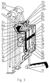
- FIG. 1 shows the basic structure of a three-part process chamber 1 with the partial chambers 1 a; 1b; 1c.
- an electron accelerator 2 is arranged as a band emitter transversely to the direction of flow of the seed to be treated.
- the electron accelerator 2 generates an electron beam 3.
- the electron beam 3 passes through a beam exit window 4 into the partial chambers 1a filled with nitrogen or air; 1b; 1c.
- an electron field 3a; 3b; 3c which acts on the seed 5 which is conveyed in free fall.
- the seed 5 is fed to the inlet funnel 6a.
- a vibration conveyor 8a separates the seeds 5 into a transparent curtain, which is guided through the electron field 3a in free fall.
- a cellular wheel sluice 9a serves as a seal for discharging the seed 5 from the partial chamber 1a.
- a conveyor 10a feeds the seed 5 to the inlet funnel 6b. The seed passes through the vibration conveyor 8b, the sub-chamber 1b and is subjected to the electron action a second time, in the electron field 3b. The seeds are discharged from the sub-chamber 1b through the rotary valve 9b. With the aid of the conveying device 10b, the seed 5 is again transported upwards and fed to the vibration conveyor 8c.
- the seed 5 passes through the electron field 3c in free fall and is exposed to the electron action a third time.
- a sufficiently homogeneous distribution of the energy dose on almost every grain is achieved by transferring the energy dose in 3 steps, each time with a new change in the position of the individual grains of the seed 5.
- the conveying device 11 takes over the removal of the seeds 5 in a known manner.
- the electron accelerator 2 with the beam exit window 4 and the subchambers 1a, 1b and 1c are housed in a radiation protection covering 12.
- the S-shaped design of the radiation protection covering in the area of the vibration conveyor 8a; 8b; 8c and at the cellular wheel locks 9a; 9b, 9c ensures radiation tightness.
- the exchange of the gas in the sub-chambers 1a; 1b; 1c, which are filled with air or nitrogen, with the ambient air is on the seed exit side through the rotary valve 9a; 9b; 9c prevented.
- the cooling gas used to cool the jet exit window 4 is identical to the gas in the subchambers 1a; 1b; 1c and is guided past the jet exit window 4 through a nozzle system 14 with gas inlet 15 and gas outlet 16.
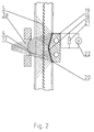
- FIG. 2 shows a section as a cross section in the area of the electron field through a device for electron treatment of seeds with a profiled, roof-like electron reflector, which is also used to obtain a dose-proportional signal.
- the electrons of the electron field 3a appear through the beam exit window 4 Atmospheric pressure, cross for the most part a grid 17, which to protect the Beam exit window 4 serves in front of ricocheting seeds, and partially hit the isolated flow of seeds 5.
- the seed 5 is due to the electrons hitting from different spatial directions acts, which in addition to the multiple pass of the seeds 5 a more homogeneous Distribution of the energy dose around the circumference of each seed causes.
- the electron reflector 18 is mounted on a cooled holder 19 and through a Insulator 20 electrically isolated from this.
- a voltage measuring device 22 enables the voltage drop to be measured over the resistor 21 and so the acquisition of a dose-dependent signal. This signal is fed to a process computer in a known manner and for the purpose the process control further processed.
Landscapes
- Chemical & Material Sciences (AREA)
- Organic Chemistry (AREA)
- Life Sciences & Earth Sciences (AREA)
- Chemical Kinetics & Catalysis (AREA)
- Plasma & Fusion (AREA)
- Environmental Sciences (AREA)
- Physics & Mathematics (AREA)
- Engineering & Computer Science (AREA)
- Soil Sciences (AREA)
- Health & Medical Sciences (AREA)
- General Health & Medical Sciences (AREA)
- Toxicology (AREA)
- Physical Or Chemical Processes And Apparatus (AREA)
- Preparation Of Fruits And Vegetables (AREA)
- Disintegrating Or Milling (AREA)
- Storage Of Fruits Or Vegetables (AREA)
Abstract
Description
Die Erfindung bezieht sich auf ein Verfahren und eine Einrichtung zur Behandlung von Schüttgut, vorzugsweise von Saatgut, mit beschleunigten Elektronen. Das bevorzugte Anwendungsgebiet ist die phytosanitäre Behandlung von Saatgut gegen samenbürtige Schaderreger, die überwiegend in der Samenschale der Samenkörner angesiedelt sind. Weitere Anwendungsgebiete sind die Oberflächensterilisation infizierter Kunststoff-Einwegartikel nach der Zerkleinerung im Recyclingprozess, die chemische Oberflächenaktivierung sowie die Durchführung anderer strahlenchemischer Prozesse an Schüttgut.The invention relates to a method and a device for the treatment of Bulk, preferably seeds, with accelerated electrons. The preferred The field of application is the phytosanitary treatment of seeds against seeds Pathogens that are predominantly located in the seed coat of the seeds. Further areas of application are the surface sterilization of infected plastic disposable articles after shredding in the recycling process, the chemical surface activation as well as the implementation of other radiation chemical processes on bulk material.
Es sind verschiedene Verfahren und die entsprechenden Einrichtungen zur Behandlung von
Schüttgut mit beschleunigten Elektronen in verschiedenen Ausführungen - angepasst an
das zu behandelnde Gut - bekannt.
So wird in einer evakuierten Kammer durch gegenüberliegende Anordnung zweier
Elektronenbeschleuniger ein Elektronenfeld mit entgegengesetzten Geschwindigkeitskomponenten
der Elektronen erzeugt, durch welches das Schüttgut im freien Fall in einem
ausgedehnten transparenten Strom geführt wird (DD 291 705). Zur Elektronenbehandlung
wird das Schüttgut in die Kammer über Zellenradschleusen eingeschleust und nach dem
Elektronenstrahlprozess wieder ausgeschleust. Der Nachteil solcher Einrichtungen ist jedoch
der hohe apparative Aufwand für die Erzeugung des Elektronenfeldes, da mindestens zwei
Elektronenbeschleuniger erforderlich sind, und der hohe vakuumtechnische Aufwand.Various methods and the corresponding devices for treating bulk material with accelerated electrons in various designs - adapted to the material to be treated - are known.
In an evacuated chamber, an electron field with opposite velocity components of the electrons is generated by the arrangement of two electron accelerators opposite each other, through which the bulk material is guided in free fall in an extensive transparent stream (DD 291 705). For electron treatment, the bulk material is introduced into the chamber via cellular wheel locks and then removed again after the electron beam process. However, the disadvantage of such devices is the high outlay in terms of equipment for generating the electron field, since at least two electron accelerators are required, and the high outlay in terms of vacuum technology.
Es ist außerdem bekannt, ein Elektronenfeld mit entgegengesetzten Geschwindigkeitskomponenten dadurch zu erzeugen, dass der Elektronenstrahl, nachdem er den Strom der Schüttgutteilchen passiert hat, durch eine magnetische Umlenkung auf den Teilchenstrom zurückgelenkt wird. Einrichtungen dieser Art vermeiden den Aufwand für einen zweiten Elektronenbeschleuniger. Der Nachteil dieses Verfahrens besteht jedoch darin, dass durch den relativ langen Weg, den der Elektronenstrahl in der Prozesskammer durchläuft, ein wesentlich besseres Vakuum benötigt wird, was bezüglich der Vakuumerzeugung einen noch höheren apparativen Aufwand erfordert.It is also known to have an electron field with opposite speed components by generating the electron beam after it has the current of Bulk particles has passed through a magnetic deflection on the particle stream is steered back. Facilities of this type avoid the expense of a second Electron accelerator. The disadvantage of this method, however, is that the relatively long path that the electron beam travels in the process chamber much better vacuum is needed, which is one in terms of vacuum generation requires even more equipment.
Es sind auch Verfahren und Einrichtungen bekannt, die mit zwei einander gegenüberliegenden Elektronenbeschleunigern arbeiten, wobei die Elektronen über ein Strahlaustrittsfenster an Atmosphärendruck austreten (DE 44 34 767 C1, EP 0 705 531 B1). Das Schüttgut wird dabei ebenfalls im freien Fall durch das Elektronenfeld geführt. Bei dieser Lösung entfällt der Aufwand zur sonst erforderlichen Evakuierung der Prozesskammer. Dennoch verbleibt der Nachteil des hohen apparativen Aufwandes durch den notwendigen Einsatz von mindestens zwei Elektronenbeschleunigern.Methods and devices are also known, which have two opposite ones Electron accelerators work, the electrons passing through a beam exit window emerge at atmospheric pressure (DE 44 34 767 C1, EP 0 705 531 B1). The Bulk material is also guided through the electron field in free fall. At this Solution eliminates the expense of otherwise necessary evacuation of the process chamber. Nevertheless, the disadvantage of the high expenditure on equipment due to the necessary remains Use of at least two electron accelerators.
Es ist weiterhin bekannt, pulverförmige und körnige Materialien an Atmosphärendruck mit
Elektronen zu behandeln, wobei nur ein Elektronenbeschleuniger zum Einsatz kommt und
die zu bestrahlenden Teilchen in einem Gasstrom durch das Elektronenfeld getragen
werden (WO 98/43274). Der Gasstrom mit den zu bestrahlenden Teilchen wird durch einen
rechteckigen Kanal geführt, der an einer Seite mit einer 25 µm dicken Aluminumfolie
verschlossen ist, durch welche die Elektronen nach ihrer Ausschleusung über eine 13 µm
dicke Titanfensterfolie und Durchlaufen der Distanz bis zum Bestrahlungskanal eindringen.
Der Aluminiumfolie gegenüberliegend wird der rechteckige Kanal durch eine ebene Platte
aus einem Werkstoff hoher Ordnungszahl gebildet. Nach Durchdringen des Kanalquerschnitts
werden die Elektronen von dieser Platte zu einem gewissen Anteil rückgestreut.
Die rückgestreuten Elektronen haben eine der ursprünglichen Einfallsrichtung der
Elektronen entgegengerichtete Geschwindigkeitskomponente und ermöglichen, dass auch
die bezüglich der ursprünglichen Einfallsrichtung der Elektronen abgewandte Seite der
Teilchen einem Elektronenbeschuss ausgesetzt ist.
Von Nachteil ist, dass die Intensität der Bestrahlung durch die rückgestreuten Elektronen
wesentlich niedriger ist als die Intensität der Bestrahlung durch die unmittelbar aus dem
Strahlaustrittsfenster austretenden Elektronen, was zu einer ungleichmäßigen Bestrahlung
der einzelnen Teilchen führt. Nachteilig ist auch, dass die zum Tragen der Teilchen
erforderliche Gasgeschwindigkeit mit steigendem Verhältnis von Masse zur Oberfläche der
transportierten Teilchen stark ansteigt. Somit würden für größerkörnige Schüttgüter - wie
z.B. Weizen oder Mais - sehr hohe Gasströmungsgeschwindigkeiten erforderlich werden.
Bei diesen hohen Geschwindigkeiten würden die im Elektronenfeld übertragbaren Energiedosen
auf sehr kleine, für zahlreiche Anwendungen wesentlich zu geringe Werte begrenzt
werden. Ein weiterer Nachteil dieser bekannten Lösung besteht darin, dass die Elektronen
nach dem Austritt aus dem Elektronenbeschleuniger noch zusätzlich die den rechteckigen
Kanal verschließende Aluminiumfolie durchdringen müssen, bevor sie auf die zu
behandelnden Teilchen treffen. Dadurch erleiden die Elektronen einen zusätzlichen
unerwünschten Energieverlust. It is also known to treat powdery and granular materials at atmospheric pressure with electrons, only an electron accelerator being used and the particles to be irradiated being carried through the electron field in a gas stream (WO 98/43274). The gas flow with the particles to be irradiated is passed through a rectangular channel, which is closed on one side with a 25 µm thick aluminum foil, through which the electrons penetrate through a 13 µm thick titanium window film and pass through the distance to the radiation channel. Opposite the aluminum foil, the rectangular channel is formed by a flat plate made of a high atomic number material. After penetrating the channel cross section, the electrons are scattered back to a certain extent by this plate. The backscattered electrons have a velocity component opposite to the original direction of incidence of the electrons and enable the side of the particles facing away from the original direction of incidence of the electrons to also be exposed to electron bombardment.
The disadvantage is that the intensity of the radiation from the backscattered electrons is significantly lower than the intensity of the radiation from the electrons emerging directly from the beam exit window, which leads to uneven radiation of the individual particles. Another disadvantage is that the gas velocity required to carry the particles increases sharply as the ratio of mass to surface of the transported particles increases. This would require very high gas flow velocities for larger-sized bulk materials - such as wheat or corn. At these high speeds, the energy doses that can be transmitted in the electron field would be limited to very small values that are far too low for numerous applications. Another disadvantage of this known solution is that the electrons have to additionally penetrate the aluminum foil closing the rectangular channel after they exit the electron accelerator before they strike the particles to be treated. As a result, the electrons suffer an additional undesirable loss of energy.
Der Erfindung liegt die Aufgabe zugrunde, ein Verfahren und eine zugehörige Einrichtung zur Behandlung von Schüttgut zu schaffen, die es gestatten, unabhängig von der Teilchengröße und mit vergleichsweise geringem vakuumtechnischen Aufwand, der auf die Vakuumerzeugung des Elektronenbeschleunigers beschränkt ist, eine hinreichend gleichmäßige Behandlung der Oberfläche von Schüttgutteilchen mit beschleunigten Elektronen bei etwa Atmosphärendruck durchzuführen.The invention has for its object a method and an associated device for the treatment of bulk goods that make it possible, regardless of the particle size and with comparatively little vacuum technology, which on the Vacuum generation of the electron accelerator is limited, a sufficient uniform treatment of the surface of bulk particles with accelerated Perform electrons at about atmospheric pressure.
Erfindungsgemäß wird die Aufgabe durch das Verfahren gemäß Patentanspruch 1 gelöst.
Gegenstand des Anspruchs 8 ist eine zur Durchführung des Verfahrens geeignete
Einrichtung. Besonders vorteilhafte Ausgestaltungen sind in den Ansprüchen 2 bis 7 und 9
bis 22 beschrieben.According to the invention the object is achieved by the method according to claim 1.
The subject of
Nach dem erfindungsgemäßen Verfahren wird der Schüttgutstrom bei Atmosphärendruck mehrmals durch ein Elektronenfeld geführt. Das hat den Vorteil, dass eine technologisch bedingte Transportgeschwindigkeit, die nach einem Durchlauf zu - für eine effektive Oberflächenbehandlung - zu niedrigen Energiedosen führt, beibehalten werden kann, da durch die wiederholte Einwirkung der Elektronen auf jedes Schüttgutteilchen die Oberfläche jedes Teilchens von genügend Elektronen beaufschlagt wird.According to the method according to the invention, the bulk material flow is at atmospheric pressure passed through an electron field several times. That has the advantage of being a technological one conditional transport speed, which after one pass too - for effective Surface treatment - leading to low energy doses, can be maintained as by the repeated action of the electrons on each bulk particle Enough electrons act on the surface of each particle.
Inhomogenitäten der Intensität der Oberflächenbehandlung in einem einzelnen Durchlauf des Schüttgutstroms durch das Elektronenfeld werden ausgeglichen. Der Schüttgutstrom durchläuft mehrmals nacheinander das Elektronenfeld als ein zumindest im Bereich des Elektronenfeldes transparenter Schüttgutstrom. Beim Passieren des Elektronenfeldes wirken die Elektronen auf die Oberfläche der Teilchen ein und erzeugen nach dem ersten Durchlauf eine erste Dosisverteilung in der Teilchenoberfläche. Durch unterschiedliche Teilchenorientierung und -rotation im Elektronenfeld ist diese teilchenindividuell unterschiedlich. Die Dosisverteilung in der Oberfläche weist im Allgemeinen ein Dosismaximum und ein Dosisminimum auf. Beim Passieren des Elektronenfeldes in weiteren Durchläufen erfolgt wiederum eine Elektroneneinwirkung mit der gleichen Charakteristik. Die dadurch erzeugte Dosisverteilung wird jedoch durch die inzwischen erfolgte zufällige Bewegung der Teilchen der vorangegangenen statistisch überlagert. Damit wird die resultierende Gesamtdosisverteilung, welche sich aus der Summe der einzelnen Dosisverteilungen ergibt, mit jedem Durchlauf gleichmäßiger. Mehrfachanordnungen von Elektronenbeschleunigern zur Homogenisierung des Elektronenfeldes werden dadurch überflüssig. Es genügen einfache Elektronenreflektoren, um bereits nach wenigen Inhomogeneities in the intensity of the surface treatment in a single pass of the bulk material flow through the electron field are balanced. The bulk flow passes through the electron field several times in succession as a, at least in the region of the Electron field transparent bulk flow. Act when passing the electron field the electrons enter the surface of the particles and generate after the first Run a first dose distribution in the particle surface. By different Particle orientation and rotation in the electron field is particle-specific differently. The dose distribution in the surface generally shows a dose maximum and a dose minimum. When passing the electron field in another In turn, electron action with the same characteristics takes place. The dose distribution generated by this is, however, due to the now random Movement of the particles of the previous one is statistically superimposed. With that the resulting total dose distribution, which is the sum of the individual dose distributions results more evenly with each pass. Multiple arrangements of This accelerates electron accelerators for the homogenization of the electron field superfluous. Simple electron reflectors are sufficient to get after just a few
Durchläufen des Schüttgutstromes eine ausreichend gleichmäßige Dosisverteilung auf der
Teilchenoberfläche zu erreichen. Die Anzahl der Durchläufe ist abhängig von der benötigten
Dosishomogenität auf der Oberfläche der Teilchen.
Da somit auch die für eine magnetische Umlenkung des Elektronenstrahles erforderliche
freie Weglänge der Elektronen entfällt, kann die Behandlung an Atmosphärendruck
erfolgen. Damit ist nur für den Elektronenbeschleuniger selbst die Vakuumerzeugung nötig.
Im geringen vakuumtechnischen Aufwand und der kostengünstigen Ausführbarkeit unter
Einsatz nur eines Elektronenbeschleunigers liegen die entscheidenden Vorteile des
Verfahrens. Damit ist auch die Möglichkeit gegeben, mit relativ geringem Aufwand die
Einrichtung mobil auszuführen.Passing the bulk material flow to achieve a sufficiently uniform dose distribution on the particle surface. The number of runs depends on the required dose homogeneity on the surface of the particles.
Since the free path length of the electrons required for magnetic deflection of the electron beam is thus also eliminated, the treatment can be carried out at atmospheric pressure. This means that vacuum generation is only necessary for the electron accelerator itself. The decisive advantages of the process lie in the low expenditure on vacuum technology and the inexpensive feasibility using only one electron accelerator. This also makes it possible to carry out the installation on a mobile basis with relatively little effort.
Im Folgenden wird das erfindungsgemäße Verfahren beschrieben.The method according to the invention is described below.
In einem bekannten Elektronenbeschleuniger vom Typ mit Linearkatodensystem, vielfach
auch Bandstrahler genannt, wird ein Elektronenstrahl erzeugt, der über ein Strahlaustrittsfenster
an Atmosphäre austritt. Die Beschleunigungsspannung zur Erzeugung des
Elektronenstrahls wird entsprechend der gewünschten Eindringtiefe der Elektronen in die
Oberfläche der Teilchen des Schüttgutes angepasst und die Strahlleistung auf die zu
übertragende Energiedosis festgelegt.
Das Elektronenfeld, welches sich vor dem Strahlaustrittsfenster ausbildet, hat den
Querschnitt eines langgestreckten Rechtecks mit in Längsrichtung des Rechteckes gleichen
Eigenschaften. Vor dem Strahlaustrittsfenster wird quer zu seiner Längsrichtung in
mehreren Bereichen das Schüttgut vorbeigeführt. Die Anzahl der Bereiche richtet sich nach
der geforderten Dosishomogenität auf der Teilchenoberfläche, was die Zahl der
erforderlichen Durchläufe der Teilchen des Schüttgutes durch das Elektronenfeld bestimmt.
Jeder Durchlauf erfolgt in einem gesonderten Bereich. Die Bereiche sorgen dafür, dass der
Schüttgutstrom bei einem Durchlauf jeweils durch einen bestimmten Teil des Elektronenfeldes
geführt wird.In a known electron accelerator of the type with a linear cathode system, often also called a band emitter, an electron beam is generated which exits to the atmosphere via a beam exit window. The acceleration voltage for generating the electron beam is adjusted in accordance with the desired depth of penetration of the electrons into the surface of the particles of the bulk material and the beam power is fixed to the energy dose to be transmitted.
The electron field which forms in front of the beam exit window has the cross section of an elongated rectangle with the same properties in the longitudinal direction of the rectangle. In bulk, the bulk material is guided past the beam exit window in a direction transverse to its longitudinal direction. The number of areas depends on the required dose homogeneity on the particle surface, which determines the number of required passes of the particles of the bulk material through the electron field. Each run takes place in a separate area. The areas ensure that the bulk material flow is guided through a certain part of the electron field during one pass.
Die Einrichtung zur Durchführung des Verfahrens ist wie folgt aufgebaut: Eine Prozesskammer ist in eine der Anzahl der Durchläufe des Schüttgutes entsprechende Anzahl von Teilkammern unterteilt. Ein Elektronenbeschleuniger mit Strahlaustrittsfenster ist quer zum Schüttgutstrom angeordnet und erstreckt sich über die gesamte Breite der Prozesskammer. Die Teilkammern sind kanalartig ausgebildet und bilden dadurch Bereiche, in denen das Schüttgut behandelt wird. The device for carrying out the method is structured as follows: A process chamber is in one corresponding to the number of passes of the bulk material Number of subchambers divided. An electron accelerator with a beam exit window is arranged transversely to the bulk material flow and extends across the entire width of the Process chamber. The subchambers are channel-like and thereby form areas in which the bulk material is treated.
Die Ausgänge der ersten bis vorletzten Teilkammer sind mit Mitteln zur Förderung des Schüttgutes verbunden, die das Schüttgut vom Ausgang einer Teilkammer zum Eingang der jeweils nächsten Teilkammer transportieren. Der Eingang der ersten Teilkammer und der Ausgang der letzten Teilkammer sind mit Einrichtungen zur Zu- und Abführung des Schüttgutes zur und von der Einrichtung versehen, was einen kontinuierlichen Betrieb der Anlage ermöglicht. Bevor das Schüttgut der ersten Teilkammer zugeführt wird, wird das Schüttgut durch entsprechende mechanische Einrichtungen vereinzelt, so dass es den Bereich des Elektronenfeldes als transparenter Schüttgutstrom im freien Fall passiert. Vor dem Eintritt in den nächsten Bereich erfolgt erneut eine mechanische Vereinzelung zu einem transparenten Schüttgutstrom. Entsprechend der Anzahl der Bereiche werden diese Durchläufe mehrmals wiederholt. Nach Durchlaufen des letzten Bereiches erfolgt der Abtransport des Schüttgutes.The outputs from the first to the penultimate subchamber are provided with funds to promote the Bulk goods connected, the bulk goods from the exit of a sub-chamber to the entrance of the transport the next subchamber. The entrance of the first sub-chamber and the The exit of the last part of the chamber is equipped with facilities for the supply and discharge of the Provide bulk goods to and from the facility, which means continuous operation of the Facility enables. Before the bulk material is fed into the first subchamber, this is done Bulk goods separated by appropriate mechanical devices, so that it Passes the area of the electron field as a transparent bulk flow in free fall. In front mechanical separation occurs again when entering the next area a transparent bulk flow. According to the number of areas, these are Runs repeated several times. After passing through the last area, the Removal of the bulk goods.
Die Elektronen des Elektronenfeldes haben eine bevorzugte Geschwindigkeitskomponente
in Strahleinfallsrichtung. Vorteilhafterweise sind gegenüber dem Strahlaustrittsfenster
Elektronenreflektoren angeordnet. Die an diesen Elektronenreflektoren rückgestreuten
Elektronen haben jedoch eine geringere Intensität als die im Elektronenstrahl einfallenden
Elektronen. Dadurch kommt es zu einer inhomogenen Dosisverteilung auf der Teilchenoberfläche.
Die Vereinzelung in einen transparenten Schüttgutstrom gewährleistet, dass
sich die einzelnen Teilchen des Schüttgutes nicht gegenseitig abschatten und damit die
Wirksamkeit der Elektronenbehandlung vermindert wird. Gleichzeitig sorgen die
Bewegungsabläufe bei Förderung und Vereinzelung dafür, dass die Teilchen des Schüttgutes
bei jedem Durchlauf eine andere Orientierung bezüglich des Elektronenfeldes haben.
Die einzelnen Dosisverteilungen auf der Oberfläche der Schüttgutpartikel werden statistisch
überlagert.
Das Minimum der pro Flächenelement übertragenen Dosis liegt etwa beim halben
Maximalwert, welcher auf der dem Strahlaustrittsfenster zugewandten Teilchenseite
auftrifft. Diese Dosisverteilung auf der Teilchenoberfläche bedingt, dass bereits nach drei
Durchläufen des Schüttgutes eine für die meisten Anwendungen ausreichende
Homogenität der Oberflächenbehandlung erzielt wird.The electrons of the electron field have a preferred velocity component in the direction of the beam. Electron reflectors are advantageously arranged opposite the beam exit window. However, the backscattered electrons at these electron reflectors have a lower intensity than the electrons incident in the electron beam. This leads to an inhomogeneous dose distribution on the particle surface. The separation into a transparent bulk material flow ensures that the individual particles of the bulk material do not shade each other and thus the effectiveness of the electron treatment is reduced. At the same time, the movement sequences during conveyance and separation ensure that the particles of the bulk material have a different orientation with respect to the electron field with each pass. The individual dose distributions on the surface of the bulk particles are statistically superimposed.
The minimum of the dose transmitted per surface element is approximately half the maximum value which strikes the particle side facing the beam exit window. This dose distribution on the particle surface means that, after three runs of the bulk material, a sufficient homogeneity of the surface treatment is achieved for most applications.
Die Variante, bei der ein transparenter Schüttgutstrom das Elektronenfeld im freien Fall durchläuft, ist technologisch besonders leicht zu realisieren. Daneben ist es jedoch denkbar, zur Erhöhung des Durchsatzes das Schüttgut durch eine Vorrichtung am Eingang der The variant in which a transparent bulk material flow frees the electron field is technologically particularly easy to implement. In addition, it is conceivable to increase the throughput of the bulk material by a device at the entrance of the
Bereiche auf eine bestimmte Geschwindigkeit zwangsweise zu beschleunigen und die Teilchen nach dieser Vorbeschleunigung im freien Fall durch das Elektronenfeld zu führen. Eine gezielte Abbremsung der Teilchen ist vorteilhaft für besonders stoßempfindliche Schüttgüter.Forced areas to accelerate to a certain speed and the Guide particles after this pre-acceleration in free fall through the electron field. Targeted braking of the particles is advantageous for those who are particularly sensitive to shock Bulk goods.
An einem Ausführungsbeispiel wird die Erfindung näher beschrieben.
Die zugehörigen Zeichnungen zeigen in
- Fig. 1:
- eine Ansicht einer Einrichtung zur Elektronenbehandlung von Saatgut mit einem Elektronenbeschleuniger mit Strahlaustrittsfenster und einem Fördersystem für einen dreimaligen Durchlauf des Saatgutes durch das Elektronenfeld,
- Fig. 2:
- einen Querschnitt durch einen Teil der Einrichtung gemäß Fig. 1 im Bereich des Elektronenfeldes.
The associated drawings show in
- Fig. 1:
- 1 shows a view of a device for electron treatment of seeds with an electron accelerator with a beam exit window and a conveyor system for a three-time passage of the seeds through the electron field,
- Fig. 2:
- a cross section through part of the device of FIG. 1 in the region of the electron field.
In Fig. 1 ist der prinzipielle Aufbau einer dreigeteilten Prozesskammer 1 mit den Teilkammern
1a; 1b; 1c dargestellt. Auf einer Seite der Teilkammern 1a; 1b; 1c ist ein
Elektronenbeschleuniger 2 als Bandstrahler quer zur Durchlaufrichtung des zu
behandelnden Saatgutes angeordnet. Der Elektronenbeschleuniger 2 erzeugt einen
Elektronenstrahl 3. Durch ein Strahlaustrittsfenster 4 tritt der Elektronenstrahl 3 in die mit
Stickstoff oder Luft gefüllten Teilkammern 1a; 1b; 1c. Im Bereich vor dem Strahlaustrittsfenster
4 besteht somit in jeder Teilkammer 1a; 1b; 1c ein Elektronenfeld 3a; 3b; 3c,
welches auf das im freien Fall geförderte Saatgut 5 einwirkt.
Das Saatgut 5 wird dem Einlauftrichter 6a zugeführt. Mit Hilfe einer Dosiereinrichtung 7
erfolgt die Einstellung des erforderlichen Massendurchsatzes an Saatgut. Ein Vibrationsförderer
8a vereinzelt das Saatgut 5 zu einem transparenten Vorhang, der im freien Fall
durch das Elektronenfeld 3a geführt wird. Eine Zellradschleuse 9a als Abdichtung dient zur
Ausschleusung des Saatgutes 5 aus der Teilkammer 1a. Eine Fördereinrichtung 10a führt
das Saatgut 5 dem Einlauftrichter 6b zu.
Das Saatgut durchläuft den Vibrationsförderer 8b, die Teilkammer 1b und wird ein zweites
Mal der Elektroneneinwirkung, im Elektronenfeld 3b, unterzogen. Der Saatgutaustrag aus
der Teilkammer 1b erfolgt durch die Zellradschleuse 9b. Mit Hilfe der Fördereinrichtung 10b
wird das Saatgut 5 erneut nach oben transportiert und dem Vibrationsförderer 8c
zugeführt. In der Teilkammer 1c gelangt das Saatgut 5 im freien Fall durch das Elektronenfeld
3c und wird ein drittes Mal der Elektroneneinwirkung ausgesetzt. Durch die
Übertragung der Energiedosis in 3 Schritten mit jeweils erneuter Lageänderung der
einzelnen Körner des Saatgutes 5 wird eine ausreichend homogene Verteilung der
Energiedosis auf nahezu jedem Korn erreicht.
1 shows the basic structure of a three-part process chamber 1 with the
Nach Ausschleusung des Saatgutes 5 durch die Zellradschleuse 9c übernimmt die Fördereinrichtung
11 den Abtransport des Saatgutes 5 in bekannter Weise.
Der Elektronenbeschleuniger 2 mit Strahlaustrittsfenster 4 und die Teilkammern 1a, 1b und
1c sind in einer Strahlenschutzverkleidung 12 eingehaust. Die S-förmige Ausbildung der
Strahlenschutzverkleidung im Bereich der Vibrationsförderer 8a; 8b; 8c und an den Zellradschleusen
9a; 9b, 9c gewährleistet die Strahlendichtheit.
Der Austausch des Gases in den Teilkammern 1a; 1b; 1c, die mit Luft oder Stickstoff gefüllt
sind, mit der Umgebungsluft wird auf der Saatgutaustrittsseite durch die Zellradschleusen
9a; 9b; 9c verhindert. Zur Abdichtung der Saatgutzuführung im oberen Bereich der Einlauftrichter
6a; 6b; 6c dient die Saatgutsäule 13a; 13b; 13c, deren Füllstand durch Regeleinrichtungen
(nicht dargestellt) konstant gehalten wird. Die Abdichtung beim Anfahren
und Leerfahren der Anlage erfolgt durch gesteuerte Luftklappen (nicht dargestellt).
Das zur Kühlung des Strahlaustrittsfensters 4 dienende Kühlgas ist identisch mit dem Gas in
den Teilkammern 1a; 1b; 1c und wird durch ein Düsensystem 14 mit Gaseinlass 15 und
Gasauslass 16 an dem Strahlaustrittsfenster 4 vorbeigeführt.After the
The exchange of the gas in the sub-chambers 1a; 1b; 1c, which are filled with air or nitrogen, with the ambient air is on the seed exit side through the rotary valve 9a; 9b; 9c prevented. To seal the seed supply in the upper area of the inlet funnel 6a; 6b; 6c serves the seed column 13a; 13b; 13c, the fill level of which is kept constant by control devices (not shown). The seal when starting up and emptying the system is done by controlled air flaps (not shown). The cooling gas used to cool the
Fig. 2 zeigt einen Ausschnitt als Querschnitt im Bereich des Elektronenfeldes durch eine
Einrichtung zur Elektronenbehandlung von Saatgut mit einem profilierten, dachartig ausgebildeten
Elektronenreflektor, der gleichzeitig zur Gewinnung eines dosisproportionalen
Signals dient.
2 shows a section as a cross section in the area of the electron field through a device for electron treatment of seeds with a profiled, roof-like electron reflector, which is also used to obtain a dose-proportional signal.
Die Elektronen des Elektronenfeldes 3a treten durch das Strahlaustrittsfenster 4 an
Atmosphärendruck aus, durchqueren zum größten Teil ein Gitter 17, das zum Schutz des
Strahlaustrittsfensters 4 vor abprallenden Saatkörnern dient, und treffen teilweise auf den
vereinzelten Strom des Saatgutes 5. Der übrige Teil der Elektronen trifft ohne Wechselwirkung
mit dem Saatgut 5 auf den profilierten Elektronenreflektor 18 und wird so
reflektiert, dass die zuvor aus einer Vorzugsrichtung auftreffenden Elektronen des
Elektronenfeldes 3a in zwei unterschiedliche Richtungen rückgestreut werden. Das Saatgut
5 wird durch die aus verschiedenen Raumrichtungen auftreffenden Elektronen
beaufschlagt, was zusätzlich zum Mehrfachdurchlauf des Saatgutes 5 eine homogenere
Verteilung der Energiedosis am Umfang eines jeden Saatkornes bewirkt.The electrons of the
Der Elektronenreflektor 18 ist auf einem gekühlten Halter 19 montiert und durch einen
Isolator 20 von diesem elektrisch getrennt. Der Anteil des auf den Elektronenreflektor 18
treffenden Elektronenstromes, der nicht zurückgestreut wird, fließt über einen Widerstand
21 gegen Erde ab. Ein Spannungsmessgerät 22 ermöglicht die Messung des Spannungsabfalles
über dem Widerstand 21 und so die Gewinnung eines dosisabhängigen Signals.
Dieses Signal wird in bekannter Weise einem Prozessrechner zugeführt und zum Zwecke
der Prozesssteuerung weiterverarbeitet.The
Claims (22)
Applications Claiming Priority (2)
| Application Number | Priority Date | Filing Date | Title |
|---|---|---|---|
| DE19942142 | 1999-09-03 | ||
| DE19942142A DE19942142B4 (en) | 1999-09-03 | 1999-09-03 | Process and device for treating bulk material, preferably seed, with accelerated electrons |
Publications (2)
| Publication Number | Publication Date |
|---|---|
| EP1080623A1 true EP1080623A1 (en) | 2001-03-07 |
| EP1080623B1 EP1080623B1 (en) | 2004-12-29 |
Family
ID=7920729
Family Applications (1)
| Application Number | Title | Priority Date | Filing Date |
|---|---|---|---|
| EP00118138A Expired - Lifetime EP1080623B1 (en) | 1999-09-03 | 2000-08-29 | Method and device for the treatment of bulk material, particularly seeds, with accelerated electrons |
Country Status (3)
| Country | Link |
|---|---|
| EP (1) | EP1080623B1 (en) |
| AT (1) | ATE285669T1 (en) |
| DE (2) | DE19942142B4 (en) |
Cited By (7)
| Publication number | Priority date | Publication date | Assignee | Title |
|---|---|---|---|---|
| EP1285562A1 (en) * | 2001-08-21 | 2003-02-26 | Ion Beam Applications S.A. | Method and installation for irradiating bulk material |
| DE102012209434A1 (en) | 2012-06-04 | 2013-12-05 | EVONTA - Service GmbH | Method and device for disinfecting free-flowing products, preferably seeds, with accelerated electrons |
| WO2013182504A1 (en) * | 2012-06-04 | 2013-12-12 | Evonta-Service Gmbh | Method and device for disinfecting pourable products, preferably seeds, with ultraviolet light (uv radiation) |
| EP3528273A1 (en) | 2018-02-20 | 2019-08-21 | Bühler AG | Device and method for pasteurising and/or sterilising particulate material |
| CN111741774A (en) * | 2018-02-20 | 2020-10-02 | 布勒股份公司 | Apparatus and method for disinfecting and/or sterilizing particulate material |
| US10849333B2 (en) | 2016-08-20 | 2020-12-01 | Buehler Ag | Devices and methods for pasteurizing and/or sterilizing particulate material, and cartridge |
| CN113994791A (en) * | 2021-10-29 | 2022-02-01 | 山东省科学院自动化研究所 | Conveying device and method for electron ray seed sterilization treatment |
Families Citing this family (17)
| Publication number | Priority date | Publication date | Assignee | Title |
|---|---|---|---|---|
| WO2007107211A1 (en) | 2006-03-20 | 2007-09-27 | Fraunhofer-Gesellschaft zur Förderung der angewandten Forschung e.V. | Device for altering the characteristics of three-dimensional shaped parts using electrons |
| DE102008007662A1 (en) | 2008-02-06 | 2009-08-13 | Robert Bosch Gmbh | Apparatus and method for the treatment of moldings by means of high-energy electron beams |
| DE102008028545A1 (en) | 2008-06-16 | 2009-12-24 | Fraunhofer-Gesellschaft zur Förderung der angewandten Forschung e.V. | Method and device for inactivating a microbiologically contaminated mass containing solid particles by means of accelerated electrons |
| DE102009051374A1 (en) * | 2009-10-30 | 2011-06-16 | Robert Bosch Gmbh | Apparatus for refelecting accelerated electrons |
| DE102012013593B4 (en) * | 2012-07-07 | 2021-10-14 | Lilas Gmbh | Device for generating an electron beam |
| EP2870115A1 (en) | 2012-07-07 | 2015-05-13 | LIMO Patentverwaltung GmbH & Co. KG | Device for producing an electron beam |
| DE102013113688B3 (en) * | 2013-12-09 | 2015-05-07 | Fraunhofer-Gesellschaft zur Förderung der angewandten Forschung e.V. | Device for applying bulk material with accelerated electrons |
| EP3284351B1 (en) | 2016-08-20 | 2019-02-27 | Bühler AG | Method of pasteurizing and/or sterilising particulate material |
| DE102017104509A1 (en) | 2017-03-03 | 2018-09-06 | Fraunhofer-Gesellschaft zur Förderung der angewandten Forschung e.V. | Apparatus for generating accelerated electrons |
| DE102017113979A1 (en) | 2017-06-23 | 2018-12-27 | Fraunhofer-Gesellschaft zur Förderung der angewandten Forschung e.V. | Apparatus for generating accelerated electrons |
| DE102018111782A1 (en) | 2018-05-16 | 2019-11-21 | Fraunhofer-Gesellschaft zur Förderung der angewandten Forschung e.V. | Apparatus for generating accelerated electrons |
| DE102018124664A1 (en) | 2018-10-05 | 2020-04-09 | Fraunhofer-Gesellschaft zur Förderung der angewandten Forschung e.V. | Process for inactivating biologically active components within a liquid |
| DE102019134558B3 (en) | 2019-12-16 | 2021-03-11 | Fraunhofer-Gesellschaft zur Förderung der angewandten Forschung e.V. | Device and method for applying accelerated electrons to gaseous media |
| DE102021127146B3 (en) | 2021-10-19 | 2023-02-23 | Fraunhofer-Gesellschaft zur Förderung der angewandten Forschung eingetragener Verein | Device for charging bulk material with accelerated electrons |
| DE102021127145A1 (en) | 2021-10-19 | 2023-04-20 | Fraunhofer-Gesellschaft zur Förderung der angewandten Forschung eingetragener Verein | Device for charging bulk material with accelerated electrons |
| DE102021127147B3 (en) | 2021-10-19 | 2023-03-02 | Fraunhofer-Gesellschaft zur Förderung der angewandten Forschung eingetragener Verein | Device for charging bulk material with accelerated electrons |
| DE102022114434B4 (en) | 2022-06-08 | 2024-01-11 | Fraunhofer-Gesellschaft zur Förderung der angewandten Forschung eingetragener Verein | Ring-shaped device for generating accelerated electrons |
Citations (4)
| Publication number | Priority date | Publication date | Assignee | Title |
|---|---|---|---|---|
| US4048504A (en) * | 1974-12-23 | 1977-09-13 | Sulzer Brothers Limited | Method and apparatus for treating flowable material |
| DE2731569A1 (en) * | 1977-07-06 | 1979-05-23 | Sulzer Ag | Radiation treatment of granular material - giving precise dosing without mechanical damage |
| US4633611A (en) * | 1984-12-31 | 1987-01-06 | Bakish Materials Corporation | Process and apparatus for disinfecting seeds |
| DD242337A1 (en) * | 1983-01-12 | 1987-01-28 | Klaus Gaber | PROCESS FOR SEEDING SEEDS |
Family Cites Families (12)
| Publication number | Priority date | Publication date | Assignee | Title |
|---|---|---|---|---|
| DD238715A1 (en) * | 1984-03-02 | 1986-09-03 | Ardenne Manfred | PROCESS FOR SEEDING SEEDS |
| DD291702A5 (en) * | 1990-01-25 | 1991-07-11 | Wtoez Der Brau- Und Malzindustrie,De | PROCESS FOR PREPARING USING FILTER LAYERS USED IN PARTICULAR IN THE BEVERAGE INDUSTRY |
| DK0513081T3 (en) * | 1990-01-31 | 1995-02-06 | Pfitzner Christian Als Gesells | Procedure for combating pests carried by the seed or soil by seed material treatment |
| DK0513135T3 (en) * | 1990-01-31 | 1994-11-14 | Ardenne Anlagentech Gmbh | Method and device for processing seed material |
| DD291677B5 (en) * | 1990-01-31 | 1993-11-11 | Ardenne Anlagentech Gmbh | METHOD AND DEVICE FOR SEED TREATMENT |
| DD291705B5 (en) * | 1990-01-31 | 1995-08-10 | Ardenne Anlagentech Gmbh | Device and method for the electron irradiation of bulk material |
| EP0513080B1 (en) * | 1990-01-31 | 1994-07-20 | PFITZNER, Christian (als Gesellschafter der Gesellschaft für Umweltschutzberatung und -technik GbR) | Process and device for electron beam treatment of particulates |
| DD291679A5 (en) * | 1990-01-31 | 1991-07-11 | Inst Pflanzenschutz Forschung | METHOD FOR THE TREATMENT OF SEED AND FLOOR-PROOF DAMAGE TOOLS BY SEED TREATMENT |
| DD291704B5 (en) * | 1990-01-31 | 1995-08-10 | Ardenne Anlagentech Gmbh | Method and device for treating bulk material with electron beams |
| DD291678A5 (en) * | 1990-01-31 | 1991-07-11 | Wissenschaftlich Techn Zentrum | PROCESS FOR SEED TREATMENT |
| DE4434767C1 (en) * | 1994-09-29 | 1996-02-22 | Fraunhofer Ges Forschung | Device for electron treatment of bulk material, preferably of seed |
| US5801387A (en) * | 1996-03-28 | 1998-09-01 | Electron Processing Systems, Inc. | Method of and apparatus for the electron beam treatment of powders and aggregates in pneumatic transfer |
-
1999
- 1999-09-03 DE DE19942142A patent/DE19942142B4/en not_active Expired - Fee Related
-
2000
- 2000-08-29 AT AT00118138T patent/ATE285669T1/en not_active IP Right Cessation
- 2000-08-29 EP EP00118138A patent/EP1080623B1/en not_active Expired - Lifetime
- 2000-08-29 DE DE50009083T patent/DE50009083D1/en not_active Expired - Lifetime
Patent Citations (4)
| Publication number | Priority date | Publication date | Assignee | Title |
|---|---|---|---|---|
| US4048504A (en) * | 1974-12-23 | 1977-09-13 | Sulzer Brothers Limited | Method and apparatus for treating flowable material |
| DE2731569A1 (en) * | 1977-07-06 | 1979-05-23 | Sulzer Ag | Radiation treatment of granular material - giving precise dosing without mechanical damage |
| DD242337A1 (en) * | 1983-01-12 | 1987-01-28 | Klaus Gaber | PROCESS FOR SEEDING SEEDS |
| US4633611A (en) * | 1984-12-31 | 1987-01-06 | Bakish Materials Corporation | Process and apparatus for disinfecting seeds |
Cited By (15)
| Publication number | Priority date | Publication date | Assignee | Title |
|---|---|---|---|---|
| EP1285562A1 (en) * | 2001-08-21 | 2003-02-26 | Ion Beam Applications S.A. | Method and installation for irradiating bulk material |
| WO2003017747A1 (en) * | 2001-08-21 | 2003-03-06 | Ion Beam Applications S.A. | Method and installation for irradiating bulk material |
| CN1316865C (en) * | 2001-08-21 | 2007-05-23 | 离子束应用股份有限公司 | Method and installation for irradiating bulk material |
| US7513193B2 (en) | 2001-08-21 | 2009-04-07 | Ion Beam Applications S.A. | Method and installation for irradiating bulk material |
| WO2013182500A1 (en) | 2012-06-04 | 2013-12-12 | Evonta-Service Gmbh | Method and device for disinfecting pourable products, preferably seeds, with accelerated electrons |
| WO2013182504A1 (en) * | 2012-06-04 | 2013-12-12 | Evonta-Service Gmbh | Method and device for disinfecting pourable products, preferably seeds, with ultraviolet light (uv radiation) |
| DE102012209434A1 (en) | 2012-06-04 | 2013-12-05 | EVONTA - Service GmbH | Method and device for disinfecting free-flowing products, preferably seeds, with accelerated electrons |
| US9736977B2 (en) | 2012-06-04 | 2017-08-22 | Evonta-Service Gmbh | Method and device for disinfecting pourable products, preferably seeds, with accelerated electrons |
| US10849333B2 (en) | 2016-08-20 | 2020-12-01 | Buehler Ag | Devices and methods for pasteurizing and/or sterilizing particulate material, and cartridge |
| US11166472B2 (en) | 2016-08-20 | 2021-11-09 | Bühler AG | Devices and methods for pasteurizing and/or sterilizing particulate material, and cartridge |
| EP3528273A1 (en) | 2018-02-20 | 2019-08-21 | Bühler AG | Device and method for pasteurising and/or sterilising particulate material |
| CN111741774A (en) * | 2018-02-20 | 2020-10-02 | 布勒股份公司 | Apparatus and method for disinfecting and/or sterilizing particulate material |
| US11896041B2 (en) | 2018-02-20 | 2024-02-13 | Bühler AG | Device and method for pasteurizing and/or sterilizing particulate material |
| US11963540B2 (en) | 2018-02-20 | 2024-04-23 | Bühler AG | Device and method for pasteurizing and/or sterilizing particulate material |
| CN113994791A (en) * | 2021-10-29 | 2022-02-01 | 山东省科学院自动化研究所 | Conveying device and method for electron ray seed sterilization treatment |
Also Published As
| Publication number | Publication date |
|---|---|
| DE19942142B4 (en) | 2004-04-15 |
| DE50009083D1 (en) | 2005-02-03 |
| DE19942142A1 (en) | 2001-03-15 |
| ATE285669T1 (en) | 2005-01-15 |
| EP1080623B1 (en) | 2004-12-29 |
Similar Documents
| Publication | Publication Date | Title |
|---|---|---|
| DE19942142B4 (en) | Process and device for treating bulk material, preferably seed, with accelerated electrons | |
| EP2854497B1 (en) | Method and device for disinfection granular products, such as seed, with accelerated electrons. | |
| EP1999775B1 (en) | Device and method for altering the characteristics of three-dimensional shaped parts using electrons and use of said method | |
| EP3079803B1 (en) | Apparatus for subjecting bulk material to the action of accelerated electrons | |
| EP1982921B1 (en) | Device and method for sterilising containers | |
| EP2650022B1 (en) | Method and device for radiation-based sterilisation of container closures | |
| EP0513080B1 (en) | Process and device for electron beam treatment of particulates | |
| DE102006020483A1 (en) | Method and device for treating seed with a physical plasma at atmospheric pressure | |
| EP0705531B1 (en) | Apparatus for electronic treatment of granules, specially seeds | |
| EP2306792B1 (en) | Method and device for treating objects with a physical plasma at atmospheric pressure | |
| EP2854498A1 (en) | Method and device for disinfecting pourable products, preferably seeds, with ultraviolet light (uv radiation) | |
| EP2024080A1 (en) | Method and device for treating bulk material with a physical plasma at atmospheric pressure | |
| DE102021127147B3 (en) | Device for charging bulk material with accelerated electrons | |
| DD291705B5 (en) | Device and method for the electron irradiation of bulk material | |
| DE3427315A1 (en) | Continuous system for treating coated mouldings with high-energy radiation under an inert gas atmosphere | |
| DE102021127146B3 (en) | Device for charging bulk material with accelerated electrons | |
| DD291704A5 (en) | Method and device for treating bulk material with electron beams | |
| DE19901058C2 (en) | Device and method for degrading and / or converting chemical and / or biological contaminants in a fluid | |
| EP3527230B1 (en) | Device and method for pasteurising and/or sterilising particulate material | |
| DD291705A5 (en) | Device and method for the electron irradiation of bulk material | |
| DE2141376C3 (en) | Device for generating relativistic electron beam pulses with magnetic self-focusing | |
| EP1416514A1 (en) | Electron accelerator for treatment of tubular or elongated products | |
| CH656768A5 (en) | ELECTRONIC ACCELERATOR. | |
| DE1170562B (en) | Device for irradiating matter with high-energy electrons |
Legal Events
| Date | Code | Title | Description |
|---|---|---|---|
| PUAI | Public reference made under article 153(3) epc to a published international application that has entered the european phase |
Free format text: ORIGINAL CODE: 0009012 |
|
| 17P | Request for examination filed |
Effective date: 20000829 |
|
| AK | Designated contracting states |
Kind code of ref document: A1 Designated state(s): AT BE CH CY DE DK ES FI FR GB GR IE IT LI LU MC NL PT SE |
|
| AX | Request for extension of the european patent |
Free format text: AL;LT;LV;MK;RO;SI |
|
| AKX | Designation fees paid |
Free format text: AT BE CH CY DE DK ES FI FR GB GR IE IT LI LU MC NL PT SE |
|
| 17Q | First examination report despatched |
Effective date: 20021203 |
|
| RAP1 | Party data changed (applicant data changed or rights of an application transferred) |
Owner name: FRAUNHOFER-GESELLSCHAFT ZUR FOERDERUNG DERANGEWAND |
|
| GRAP | Despatch of communication of intention to grant a patent |
Free format text: ORIGINAL CODE: EPIDOSNIGR1 |
|
| GRAS | Grant fee paid |
Free format text: ORIGINAL CODE: EPIDOSNIGR3 |
|
| GRAA | (expected) grant |
Free format text: ORIGINAL CODE: 0009210 |
|
| AK | Designated contracting states |
Kind code of ref document: B1 Designated state(s): AT BE CH CY DE DK ES FI FR GB GR IE IT LI LU MC NL PT SE |
|
| PG25 | Lapsed in a contracting state [announced via postgrant information from national office to epo] |
Ref country code: FI Free format text: LAPSE BECAUSE OF FAILURE TO SUBMIT A TRANSLATION OF THE DESCRIPTION OR TO PAY THE FEE WITHIN THE PRESCRIBED TIME-LIMIT Effective date: 20041229 Ref country code: IE Free format text: LAPSE BECAUSE OF FAILURE TO SUBMIT A TRANSLATION OF THE DESCRIPTION OR TO PAY THE FEE WITHIN THE PRESCRIBED TIME-LIMIT Effective date: 20041229 Ref country code: GB Free format text: LAPSE BECAUSE OF FAILURE TO SUBMIT A TRANSLATION OF THE DESCRIPTION OR TO PAY THE FEE WITHIN THE PRESCRIBED TIME-LIMIT Effective date: 20041229 Ref country code: NL Free format text: LAPSE BECAUSE OF FAILURE TO SUBMIT A TRANSLATION OF THE DESCRIPTION OR TO PAY THE FEE WITHIN THE PRESCRIBED TIME-LIMIT Effective date: 20041229 Ref country code: ES Free format text: LAPSE BECAUSE OF FAILURE TO SUBMIT A TRANSLATION OF THE DESCRIPTION OR TO PAY THE FEE WITHIN THE PRESCRIBED TIME-LIMIT Effective date: 20041229 |
|
| REG | Reference to a national code |
Ref country code: GB Ref legal event code: FG4D Free format text: NOT ENGLISH |
|
| REG | Reference to a national code |
Ref country code: CH Ref legal event code: NV Representative=s name: PA ALDO ROEMPLER Ref country code: CH Ref legal event code: EP |
|
| REG | Reference to a national code |
Ref country code: IE Ref legal event code: FG4D Free format text: GERMAN |
|
| REF | Corresponds to: |
Ref document number: 50009083 Country of ref document: DE Date of ref document: 20050203 Kind code of ref document: P |
|
| PG25 | Lapsed in a contracting state [announced via postgrant information from national office to epo] |
Ref country code: SE Free format text: LAPSE BECAUSE OF FAILURE TO SUBMIT A TRANSLATION OF THE DESCRIPTION OR TO PAY THE FEE WITHIN THE PRESCRIBED TIME-LIMIT Effective date: 20050329 Ref country code: DK Free format text: LAPSE BECAUSE OF FAILURE TO SUBMIT A TRANSLATION OF THE DESCRIPTION OR TO PAY THE FEE WITHIN THE PRESCRIBED TIME-LIMIT Effective date: 20050329 Ref country code: GR Free format text: LAPSE BECAUSE OF FAILURE TO SUBMIT A TRANSLATION OF THE DESCRIPTION OR TO PAY THE FEE WITHIN THE PRESCRIBED TIME-LIMIT Effective date: 20050329 |
|
| NLV1 | Nl: lapsed or annulled due to failure to fulfill the requirements of art. 29p and 29m of the patents act | ||
| GBV | Gb: ep patent (uk) treated as always having been void in accordance with gb section 77(7)/1977 [no translation filed] |
Effective date: 20041229 |
|
| REG | Reference to a national code |
Ref country code: IE Ref legal event code: FD4D |
|
| PGFP | Annual fee paid to national office [announced via postgrant information from national office to epo] |
Ref country code: FR Payment date: 20050819 Year of fee payment: 6 |
|
| PG25 | Lapsed in a contracting state [announced via postgrant information from national office to epo] |
Ref country code: CY Free format text: LAPSE BECAUSE OF FAILURE TO SUBMIT A TRANSLATION OF THE DESCRIPTION OR TO PAY THE FEE WITHIN THE PRESCRIBED TIME-LIMIT Effective date: 20050829 Ref country code: AT Free format text: LAPSE BECAUSE OF NON-PAYMENT OF DUE FEES Effective date: 20050829 |
|
| PG25 | Lapsed in a contracting state [announced via postgrant information from national office to epo] |
Ref country code: MC Free format text: LAPSE BECAUSE OF NON-PAYMENT OF DUE FEES Effective date: 20050831 Ref country code: LI Free format text: LAPSE BECAUSE OF NON-PAYMENT OF DUE FEES Effective date: 20050831 Ref country code: BE Free format text: LAPSE BECAUSE OF NON-PAYMENT OF DUE FEES Effective date: 20050831 Ref country code: CH Free format text: LAPSE BECAUSE OF NON-PAYMENT OF DUE FEES Effective date: 20050831 Ref country code: LU Free format text: LAPSE BECAUSE OF NON-PAYMENT OF DUE FEES Effective date: 20050831 |
|
| PLBE | No opposition filed within time limit |
Free format text: ORIGINAL CODE: 0009261 |
|
| STAA | Information on the status of an ep patent application or granted ep patent |
Free format text: STATUS: NO OPPOSITION FILED WITHIN TIME LIMIT |
|
| ET | Fr: translation filed | ||
| 26N | No opposition filed |
Effective date: 20050930 |
|
| REG | Reference to a national code |
Ref country code: CH Ref legal event code: PL |
|
| PGFP | Annual fee paid to national office [announced via postgrant information from national office to epo] |
Ref country code: IT Payment date: 20060831 Year of fee payment: 7 |
|
| BERE | Be: lapsed |
Owner name: *FRAUNHOFER-GESELLSCHAFT ZUR FORDERUNG DER ANGEWAN Effective date: 20050831 |
|
| PG25 | Lapsed in a contracting state [announced via postgrant information from national office to epo] |
Ref country code: PT Free format text: LAPSE BECAUSE OF NON-PAYMENT OF DUE FEES Effective date: 20050529 |
|
| REG | Reference to a national code |
Ref country code: FR Ref legal event code: ST Effective date: 20080430 |
|
| PG25 | Lapsed in a contracting state [announced via postgrant information from national office to epo] |
Ref country code: FR Free format text: LAPSE BECAUSE OF NON-PAYMENT OF DUE FEES Effective date: 20070831 |
|
| PG25 | Lapsed in a contracting state [announced via postgrant information from national office to epo] |
Ref country code: FR Free format text: LAPSE BECAUSE OF NON-PAYMENT OF DUE FEES Effective date: 20060831 |
|
| PG25 | Lapsed in a contracting state [announced via postgrant information from national office to epo] |
Ref country code: IT Free format text: LAPSE BECAUSE OF NON-PAYMENT OF DUE FEES Effective date: 20070829 |
|
| PGFP | Annual fee paid to national office [announced via postgrant information from national office to epo] |
Ref country code: DE Payment date: 20190822 Year of fee payment: 20 |
|
| REG | Reference to a national code |
Ref country code: DE Ref legal event code: R071 Ref document number: 50009083 Country of ref document: DE |