EP1079029A2 - Method and apparatus for the three dimensional control of a construction machine - Google Patents
Method and apparatus for the three dimensional control of a construction machine Download PDFInfo
- Publication number
- EP1079029A2 EP1079029A2 EP00118315A EP00118315A EP1079029A2 EP 1079029 A2 EP1079029 A2 EP 1079029A2 EP 00118315 A EP00118315 A EP 00118315A EP 00118315 A EP00118315 A EP 00118315A EP 1079029 A2 EP1079029 A2 EP 1079029A2
- Authority
- EP
- European Patent Office
- Prior art keywords
- height
- construction machine
- signal
- laser transmitter
- laser
- Prior art date
- Legal status (The legal status is an assumption and is not a legal conclusion. Google has not performed a legal analysis and makes no representation as to the accuracy of the status listed.)
- Withdrawn
Links
- 238000010276 construction Methods 0.000 title claims abstract description 101
- 238000000034 method Methods 0.000 title claims abstract description 22
- 230000005540 biological transmission Effects 0.000 claims abstract description 10
- 238000012545 processing Methods 0.000 claims description 26
- 238000012937 correction Methods 0.000 claims description 7
- 239000007787 solid Substances 0.000 claims description 4
- 239000011269 tar Substances 0.000 description 5
- 238000010586 diagram Methods 0.000 description 4
- 238000005259 measurement Methods 0.000 description 3
- 230000033228 biological regulation Effects 0.000 description 2
- 230000000694 effects Effects 0.000 description 2
- 238000003754 machining Methods 0.000 description 2
- 239000011277 road tar Substances 0.000 description 2
- 230000007423 decrease Effects 0.000 description 1
- 230000001419 dependent effect Effects 0.000 description 1
- 238000001514 detection method Methods 0.000 description 1
- 239000013307 optical fiber Substances 0.000 description 1
- 238000007430 reference method Methods 0.000 description 1
Images


Classifications
-
- E—FIXED CONSTRUCTIONS
- E02—HYDRAULIC ENGINEERING; FOUNDATIONS; SOIL SHIFTING
- E02F—DREDGING; SOIL-SHIFTING
- E02F9/00—Component parts of dredgers or soil-shifting machines, not restricted to one of the kinds covered by groups E02F3/00 - E02F7/00
- E02F9/20—Drives; Control devices
- E02F9/2025—Particular purposes of control systems not otherwise provided for
- E02F9/2045—Guiding machines along a predetermined path
-
- E—FIXED CONSTRUCTIONS
- E01—CONSTRUCTION OF ROADS, RAILWAYS, OR BRIDGES
- E01C—CONSTRUCTION OF, OR SURFACES FOR, ROADS, SPORTS GROUNDS, OR THE LIKE; MACHINES OR AUXILIARY TOOLS FOR CONSTRUCTION OR REPAIR
- E01C19/00—Machines, tools or auxiliary devices for preparing or distributing paving materials, for working the placed materials, or for forming, consolidating, or finishing the paving
- E01C19/004—Devices for guiding or controlling the machines along a predetermined path
- E01C19/006—Devices for guiding or controlling the machines along a predetermined path by laser or ultrasound
-
- E—FIXED CONSTRUCTIONS
- E02—HYDRAULIC ENGINEERING; FOUNDATIONS; SOIL SHIFTING
- E02F—DREDGING; SOIL-SHIFTING
- E02F3/00—Dredgers; Soil-shifting machines
- E02F3/04—Dredgers; Soil-shifting machines mechanically-driven
- E02F3/76—Graders, bulldozers, or the like with scraper plates or ploughshare-like elements; Levelling scarifying devices
- E02F3/80—Component parts
- E02F3/84—Drives or control devices therefor, e.g. hydraulic drive systems
- E02F3/841—Devices for controlling and guiding the whole machine, e.g. by feeler elements and reference lines placed exteriorly of the machine
- E02F3/842—Devices for controlling and guiding the whole machine, e.g. by feeler elements and reference lines placed exteriorly of the machine using electromagnetic, optical or photoelectric beams, e.g. laser beams
-
- E—FIXED CONSTRUCTIONS
- E02—HYDRAULIC ENGINEERING; FOUNDATIONS; SOIL SHIFTING
- E02F—DREDGING; SOIL-SHIFTING
- E02F3/00—Dredgers; Soil-shifting machines
- E02F3/04—Dredgers; Soil-shifting machines mechanically-driven
- E02F3/76—Graders, bulldozers, or the like with scraper plates or ploughshare-like elements; Levelling scarifying devices
- E02F3/80—Component parts
- E02F3/84—Drives or control devices therefor, e.g. hydraulic drive systems
- E02F3/844—Drives or control devices therefor, e.g. hydraulic drive systems for positioning the blade, e.g. hydraulically
- E02F3/847—Drives or control devices therefor, e.g. hydraulic drive systems for positioning the blade, e.g. hydraulically using electromagnetic, optical or acoustic beams to determine the blade position, e.g. laser beams
-
- G—PHYSICS
- G05—CONTROLLING; REGULATING
- G05D—SYSTEMS FOR CONTROLLING OR REGULATING NON-ELECTRIC VARIABLES
- G05D1/00—Control of position, course or altitude of land, water, air, or space vehicles, e.g. automatic pilot
- G05D1/02—Control of position or course in two dimensions
- G05D1/021—Control of position or course in two dimensions specially adapted to land vehicles
- G05D1/0231—Control of position or course in two dimensions specially adapted to land vehicles using optical position detecting means
- G05D1/0234—Control of position or course in two dimensions specially adapted to land vehicles using optical position detecting means using optical markers or beacons
- G05D1/0236—Control of position or course in two dimensions specially adapted to land vehicles using optical position detecting means using optical markers or beacons in combination with a laser
-
- G—PHYSICS
- G05—CONTROLLING; REGULATING
- G05D—SYSTEMS FOR CONTROLLING OR REGULATING NON-ELECTRIC VARIABLES
- G05D1/00—Control of position, course or altitude of land, water, air, or space vehicles, e.g. automatic pilot
- G05D1/02—Control of position or course in two dimensions
- G05D1/021—Control of position or course in two dimensions specially adapted to land vehicles
- G05D1/0276—Control of position or course in two dimensions specially adapted to land vehicles using signals provided by a source external to the vehicle
- G05D1/0278—Control of position or course in two dimensions specially adapted to land vehicles using signals provided by a source external to the vehicle using satellite positioning signals, e.g. GPS
Definitions
- the present invention relates to a reference method or measuring method and in particular a measuring method for three-dimensional control or leveling of a Construction machine.
- Laser controls have been used for regulation for many years the working height of construction machinery.
- the Systems of this type use a rotating one Laser to create a horizontally rotating laser beam.
- the lens thus created defines a target plane for the construction machine.
- a mounted on the construction machine Receiver detects the lens, the working height of the Construction machine adjusted according to the generated lens if necessary.
- the rotating laser or the generated lens can be inclined conditionally.
- the laser beam is always spreads in a straight line can only be flat with this method Areas such as B. sports fields and parking spaces become.
- Another known method for controlling construction machinery becomes a target attached to the construction machinery is persecuted.
- the objective e.g. Legs Measuring plate or a prism, targeted and tracked.
- Servo motors and other electronic components are used to align the optics to the target to be pursued.
- the coordinates of the Target point or the construction machine relative to the predetermined Position of the optics can be calculated.
- the one from the total station calculated coordinates of the current location of the construction machine are sent to the computer on the construction machine. This computer then instructs according to the coordinates the control systems of the construction machine. In the event of deviations appropriate control ensures correct positioning the construction machine.
- GPS global positioning satellite
- the object of the present invention is therefore to an improved method and device for three-dimensional control of a construction machine create to control construction machinery in such a way that uneven Areas can be processed in a simple manner, with high Acquisition costs can be avoided.
- This task is accomplished through a three dimensional process Controlling a construction machine according to claim 1 and a device for three-dimensional control of a construction machine according to Claim 8 solved.
- the process for three-dimensional control of a construction machine used according to the present invention global position signal and a laser transmitter with one stationary location and has the following steps: Receive the global position signal; Determine one Soli height of a work tool of the construction machine from the global position signal; Setting the laser transmitter to with regard to its location, a height signal indicating the solo height to create; and controlling the work tool of the Construction machine depending on the height signal.
- an apparatus created for three-dimensional control of a construction machine has the following features: a first receiving device, which receives a global position signal; a laser transmitter with a stationary location, which generates an altitude signal; and a processing device, the one from the received global position signal Soli height of a work tool of the construction machine determined and generates a first control signal for the laser transmitter, to set the laser transmitter with regard to its location in such a way that the height signal generated by the laser transmitter indicates the solo height; the construction machine the height signal receives and the working tool depending on the height signal controls.
- the altitude determination is less accurate than the determination of the longitude or latitude.
- Construction projects are, however, the requirements for the measuring accuracy or the limit values are stored exactly the other way round, so that, for example, typical limit values with regard to the height in Millimeter range, while accuracy regarding the horizontal plane is in the centimeter range.
- the system of the present invention meets these requirements Calculation by using the rotary laser system to determine the Height of the construction machine is used, and the GPS system Determination of the horizontal coordinates is used.
- a method and a device for controlling construction machinery created a laser for height determination and a GPS system used for horizontal location determination.
- a variable inclination setting of at least one axis of rotation of a rotating laser digital terrain models can be processed become.
- the transmission device uses a rotating laser with an axis of rotation, which is controlled so that by the rotating laser generated light level at the first and second Coordinate of the construction machine has a predetermined target height, to serve as a height reference for a laser receiver.
- a first and a second coordinate of the Construction machine with respect to two axes such as. B. the longitude and the latitude of the construction machine, where a third coordinate or the height of the construction machine the generated light plane is determined.
- the advantages of the present invention are that although simple systems available on the market, such as B. the rotary laser system and the GPS system used uneven surfaces can be processed.
- the present invention therefore provides that the coordinate information received by the GPS signal by means of a radio signal to a processing device be sent near the Rotation laser is placed or integrated in the same is.
- a radio transmitter, the second detection device, such as e.g. B. a laser receiver, and the GPS receiver could in be grouped together so that the number of components and reduced the wiring on the construction machine become.
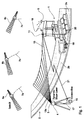
- FIG. 1 shows a road paver or a road tar machine 1 when tarring a road 2.
- Part of the road 2 is already tarred, which consequently is a machined area 2a.
- the other part of street 2 is not yet tarred and thus provides a surface to be machined 2b represents.
- the device for three-dimensional control of the paver 1 a rotating laser 3, which is removed from the construction machine at a predetermined Position is positioned and a tilt device 4 has. Furthermore, a first receiving device 5, such as B. a GPS receiver on the construction machine 1 provided that receives signals 7a-c from three satellites 9a-c. A second receiving device 11, such as. B. a Laser receiver is attached to the construction machine 1 and receives an altitude signal 13 which is output from the rotating laser 3 is produced. The height signal 13 is a light plane 13a, which is generated by the rotating laser beam.
- a Processing device 15 is in the vicinity of the rotating laser 3 arranged and with the same via a connector 17, such as B. a cable, an optical fiber or the like, connected.
- a transmission device is also on the construction machine 1 19, such as B. a radio antenna attached, which is the information obtained by the received GPS signal 7 be obtained by means of a transmission signal 21 to a Antenna 15a of the processing device 15 sends.
- the construction machine 1 is controlled in such a way that that the surface 2a processed according to predetermined solidates becomes.
- an actual position of the construction machine 1 from the GPS signal 7 and from the altitude signal 13 determines how it is in following will be described in more detail, the actual position the construction machine 1 compared with a target position is to send appropriate correction signals to the Output construction machine 1 to make a corresponding correction to effect the construction machine 1.
- the rotating laser 3 is a conventional rotating laser, which has an axis of rotation by means of the inclination device 4 can be inclined.
- the processing facility 15 controls the inclination of the rotating laser 3 in such a way that the light plane 13a on the laser receiver 11 a has a predetermined reference height, as is the case with the Fig. 3-5 is explained in more detail.
- the laser receiver 11 is a linear laser receiver with a linear output signal, that is, an output signal level of the laser receiver 11 directly proportional to the determined relative distance to the reference height in vertical direction, so that especially when activated of proportional valves (not shown) of the construction machine 1 there is an advantage in the dynamics of the control system.
- the laser receiver 11 is connected to a connecting rod 18 a tar application device 20 of the paver 1 appropriate. In this way, the laser receiver 11 is for the height signal 13 without further or without shadowing accessible through other parts of the paver 1.
- This attachment also ensures that the Height (e.g. vertical distance from sea level) of the laser receiver 11 from a working height of the tar application device 20 only differs by a constant distance.
- the processing device 15 receives via the transmission signals 21 Information from the GPS receiver 5.
- the GPS receiver 5 calculates from that of the GPS satellites 9 transmitted GPS signal 7 two coordinates of the construction machine 1 with respect to two axes, the longitude and latitude correspond (with respect to the horizontal) and sends these to the processing device 15.
- the processing device 15 controls according to these coordinates with the help the predetermined absolute position of the rotary laser 3 and the target data the inclination of the rotating laser 3 such that the laser plane 13a at the laser receiver 11 is a Has reference height, as referring to below 3-5 is described in more detail.
- the processing device determines 15 the reference height of the construction machine 1 from the target data and the GPS coordinates.
- the laser receiver 11 receives the height signal 13 or the light plane 13a and sends to a corrector 31 a signal that the deviation of the actual height of the construction machine 1 or the work tool 20 from the reference height of the light plane 13a, which is present on the laser receiver.
- a corrector 31 a signal that the deviation of the actual height of the construction machine 1 or the work tool 20 from the reference height of the light plane 13a, which is present on the laser receiver.
- the laser receiver 11 by means of the transmission device 19 (FIG. 1) the vertical Distance of the construction machine 1 relative to the reference height or the deviation of the actual height from the reference height Processing device 15 outputs.
- the processing facility 15 calculated from this relative distance and the Reference height the third coordinate of the construction machine 1 with respect a vertical axis and compares the three coordinates, d. H. the longitude value, the latitude value and the Height of the construction machine 1 with predetermined target values or a target area.
- the correction device 31 can, for example, be a or have several signal lamps that a driver of the construction machine 1 course or position changes that may need to be made Show.
- the correction device 31 can also with the steering system (not shown) of the construction machine 1 be connected to steer the course of the construction machine 1.
- the correction device 31 for example the working height of a tar application device 32 (FIG. 1) of the road tar machine 1 change to adapt the working height to the solo height.
- 3-5 is the setting of the angle of inclination the axis of rotation of the rotary laser 3 according to the preferred Described embodiment.
- the following equations is based on a right-angled, fixed coordinate system, where the x and y axes are longitude, for example or latitude, and the z-axis the height or indicates the distance to sea level.
- the used Coordinates are in a Gauss-Krüger coordinate system captured.
- FIG. 3 shows a simplified two-dimensional representation of the present invention.
- the underlying rectangular coordinate system shown with the z-axis up, the x-axis to the left and the y-axis directed towards the viewer is.
- the processing facility 15 is via the connector 17 to the rotating laser 3 connected, which has the inclination device 4.
- An arrow 35, 35 ' represents the rotating laser beam of the rotary laser 3, the head 3a, 3a 'of each Position 33, 33 'of the construction machine 1, 1' on the laser receiver 11, 11 'is directed.
- the reference number 9 is intended to be block-like represent the GPS satellites that emit the GPS signal 7.
- the laser beam 35, 35 'emitted by the rotating laser 3 serves as a height reference.
- the head 3a, 3a 'of the rotating laser 3 can be rotated by the inclination device 4 on two mutually perpendicular axes by the angles ⁇ x and ⁇ y , whereby the spatial position of the circular laser plane can be changed such that the rotating laser 3 each point in Can reach space.
- the location (X L , Y L , Z L ) of the rotating laser 3 is measured at the beginning.
- the current location coordinates (X M , Y M ) of a moving road construction machine 1 are determined by the GPS receiver 3 and sent to the processing device 15 via the transmission signal 21.
- the mutually dependent inclination angles ⁇ x and ⁇ y for the corresponding inclination axes of the rotary laser head 3a can be determined from the coordinates X L , Y L , Z L , X M , Y M and Z S thus known.
- the laser After the inclination of the rotary laser head 3a by the angles ⁇ x and ⁇ y , the laser now specifies the reference height Z S at the corresponding location (X M , Y M ).
- the mutually perpendicular inclination axes of the rotary laser 3 are rotated in succession.
- FIG. 5 shows the case in which the change in height hx of the laser plane 13a2 of FIG. 4 is not sufficient to effect the required change in height Z S -Z L. For this reason, the laser plane 13a2 inclined about the y-axis is inclined about the x'-axis. As can be seen in FIG. 5, the difference in height h y is brought about by this second inclination, so that the twice inclined laser plane 13a3 specifies the solid height Z S at the coordinates (X M , Y M ).
- ⁇ y arctan (h y /
- ) arctan ((Z S - H x ) /
- ) arctan ((Z S -tan ( ⁇ x ) *
- the reference height Z S can thus be predetermined for the laser receiver 11, so that the laser receiver 11 can determine the distance between the working height of the tar application device 20 and the desired position.
- the first receiving device 5 in the preferred Embodiment is shown as a GPS receiver, the first receiving device 5 can also include additional devices to improve the measurement accuracy to to be able to simulate the GPS signal even with shadowing.
- the GPS receiver 5 and the laser receiver 11 as well as the correction device 31 and / or the transmission device 19 can be integrated in one package, so that the number of Components in the construction machine 1 is reduced.
- the processing device 15 with the rotating laser 3 be in one piece, so that the number of necessary Components is further reduced.
- a laser with a rotating device and a tilting device is used to generate the height signal, wherein no laser plane is spanned, but a laser beam is always directed onto the laser receiver and the solo height.
- the determined absolute horizontal position X M , Y M of the construction machine 1 the predetermined absolute position (X L , Y L , Z L ) of the laser and the reference height ZS (X M , Y M ) become an angle of rotation for the Rotating device and an inclination angle for the inclination device are calculated.
- the laser receiver can also be an ordinary multi-channel Laser array or other suitable device to receive the altitude signal.
- the processing device can, for example, be a personal computer be, which has a memory in which the Setpoints of the construction project (site shape) are saved.
Abstract
Description
Die vorliegende Erfindung bezieht sich auf ein Referenzverfahren bzw. Meßverfahren und insbesondere auf ein Meßverfahren zum dreidimensionalen Steuern bzw. Nivellieren einer Baumaschine.The present invention relates to a reference method or measuring method and in particular a measuring method for three-dimensional control or leveling of a Construction machine.
Im Straßen- und Tiefbau müssen, wenn eine Baumaßnahme ansteht, zunächst die bestehenden Geländeformen vermessen werden, und ein sogenanntes Geländemodell angefertigt werden. An einem Computer wird das zu entstehende Bauvorhaben geplant. Die erzeugten Daten werden daraufhin auf der Baustelle in das Gelände übertragen. Üblicherweise werden dazu Pflöcke, und im Straßenbau auch gespannte Seile an der Fahrbahnseite verwendet. Um jedoch die Wahrscheinlichkeit von möglichen Fehlern zu reduzieren, geht man in der Bauindustrie dazu über, verbesserte, automatisierte Verfahren einzusetzen. Bei diesen Verfahren werden die Ist-Positionen der Baumaschinen mit Soll-Positionen verglichen, wobei die Positionen der Baumaschinen über verschiedene Verfahren gemessen werden.In road and civil engineering, when a construction project is due, first the existing terrain shapes are measured, and a so-called terrain model are made. The construction project to be created is planned on a computer. The generated data is then on the construction site transferred to the site. Usually this will be Pegs, and in road construction also tensioned ropes on the Roadside used. However, the probability To reduce possible errors, one goes in the construction industry about, improved, automated procedures to use. With these procedures, the actual positions of the construction machines compared with target positions, the Positions of construction machinery measured using various methods become.
Bereits seit vielen Jahren werden Lasersteuerungen zur Regelung der Arbeitshöhe von Baumaschinen verwendet. Die Systeme eines solchen Typs verwenden einen rotierenden Laser, um einen horizontal rotierenden Laserstrahl zu erzeugen. Die so erzeugte Lichtscheibe definiert eine Sollebene für die Baumaschine. Ein an der Baumaschine montierter Empfänger erfaßt die Lichtscheibe, wobei die Arbeitshöhe der Baumaschine entsprechend der erzeugten Lichtscheibe nachgeregelt wird, falls dies notwendig ist.Laser controls have been used for regulation for many years the working height of construction machinery. The Systems of this type use a rotating one Laser to create a horizontally rotating laser beam. The lens thus created defines a target plane for the construction machine. A mounted on the construction machine Receiver detects the lens, the working height of the Construction machine adjusted according to the generated lens if necessary.
Der rotierende Laser bzw. die erzeugte Lichtscheibe können bedingt geneigt werden. Da sich der Laserstrahl jedoch immer geradlinig ausbreitet, können mit diesem Verfahren nur ebene Flächen, wie z. B. Sportplätze und Parkplätze, bearbeitet werden. Zusätzlich ist bei diesen Systemen keine Regelung der Baumaschinen in einer Richtung parallel zu der Lichtebene möglich, da lediglich die Arbeitshöhe gemessen werden kann.The rotating laser or the generated lens can be inclined conditionally. However, since the laser beam is always spreads in a straight line can only be flat with this method Areas such as B. sports fields and parking spaces become. In addition, there is no regulation with these systems of the construction machines in a direction parallel to the light plane possible because only the working height is measured can.
Bei einem anderen, bekannten Verfahren zum Steuern von Baumaschinen wird ein Ziel, das an den Baumaschinen angebracht ist, verfolgt. Über eine Optik wird das Ziel, wie z. B. eine Meßplatte oder ein Prisma, angepeilt und nachverfolgt. Servomotoren und andere elektronische Komponenten werden verwendet, um die Optik auf das zu verfolgende Ziel auszurichten. Während des Nachverfolgens der Optik werden die Himmelsrichtung, die Neigung und die Entfernung der Optik zum Objekt gemessen, wobei aus diesen Daten die Koordinaten des Zielpunkts bzw. der Baumaschine relativ zu der vorbestimmten Position der Optik berechnet werden. Die von der Totalstation berechneten Koordinaten des aktuellen Ortes der Baumaschine werden an den Rechner auf der Baumaschine gesendet. Dieser Rechner instruiert dann entsprechend der Koordinaten die Steuerungssysteme der Baumaschine. Bei Abweichungen sorgt eine entsprechende Steuerung für die richtige Positionierung der Baumaschine.Another known method for controlling construction machinery becomes a target attached to the construction machinery is persecuted. The objective, e.g. Legs Measuring plate or a prism, targeted and tracked. Servo motors and other electronic components are used to align the optics to the target to be pursued. While tracking the optics, the cardinal points, the inclination and distance of the optics to Object measured, the coordinates of the Target point or the construction machine relative to the predetermined Position of the optics can be calculated. The one from the total station calculated coordinates of the current location of the construction machine are sent to the computer on the construction machine. This computer then instructs according to the coordinates the control systems of the construction machine. In the event of deviations appropriate control ensures correct positioning the construction machine.
Aufgrund der vielen verwendeten Servomotoren sind diese Systeme jedoch sehr aufwendig und verursachen hohe Kosten. Ein weiteres Problem bei diesen Systemen stellt ein Verlieren des Ziels, wie z. B. durch eine Abschattung des Ziels bezüglich der Optik, dar, sowie eine Einschränkung der Arbeitsgeschwindigkeit.Because of the many servomotors used, these are However, systems are very complex and cause high costs. Another problem with these systems is losing the target, such as B. by shadowing the target regarding the optics, as well as a limitation of the working speed.
In der jüngeren Vergangenheit werden mehr und mehr GPS-Systeme (GPS = globaler Positionierungssattelit) für Vermessungsaufgaben und die Positionierung von Baumaschinen verwendet. Dafür werden GPS-Empfänger an den Baumaschinen angebracht, die Signale von mehreren, an bekannten Positionen fest im Orbit verankerten Satelliten erfassen. Aus den Entfernungsmessungen zu den Satelliten werden die Absolutkoordinaten des GPS-Empfängers bzw. der Baumaschine berechnet. Durch diese Daten können wiederum die Ist-Position einer Baumaschine und die Soll-Position verglichen werden.In the recent past, more and more GPS systems are being used (GPS = global positioning satellite) for surveying tasks and the positioning of construction machinery used. For this, GPS receivers are used on the construction machines attached, the signals from several, at known positions Capture satellites firmly anchored in orbit. Out The distance measurements to the satellites become the absolute coordinates of the GPS receiver or the construction machine. This data can in turn determine the actual position a construction machine and the target position are compared.
Bis heute ergibt sich das Problem, daß die Koordinatendaten, die aus den GPS-Signalen ermittelt werden, für die meisten Bauvorhaben keine ausreichende Genauigkeit aufweisen. Zusätzlich verringert sich die Meßgenauigkeit mit zunehmender Geschwindigkeit des GPS-Empfängers bzw. der Baumaschine. Wie bei den vorhergehenden Systemen können zudem Abschattungen auftreten, wie z. B. durch Brücken, Tunnel oder andere Geländegegebenheiten. Ein spezifisches Problem bei den GPS-Systemen besteht darin, daß die Meßgenauigkeit derselben bezüglich der Höhe der Baumaschine geringer ist als die Meßgenauigkeit in horizontaler Richtung. Bei den meisten Bauvorhaben sind jedoch die Anforderungen an die Bearbeitungsgenauigkeit bezüglich der Höhe größer als an die Bearbeitungsgenauigkeit bezüglich der horizontalen Positionierung.To date, the problem arises that the coordinate data, which are determined from the GPS signals, for most Construction projects are not sufficiently accurate. In addition the measuring accuracy decreases with increasing Speed of the GPS receiver or the construction machine. How In the previous systems, shading can also occur occur, such as B. through bridges, tunnels or other terrain. A specific problem with the GPS systems is that the measurement accuracy of the same with respect the height of the construction machine is less than the measuring accuracy in the horizontal direction. For most construction projects however, are the requirements for machining accuracy greater in height than in machining accuracy regarding horizontal positioning.
Die Aufgabe der vorliegenden Erfindung besteht folglich darin, ein verbessertes Verfahren und eine verbesserte Vorrichtung zum dreidimensionalen Steuern einer Baumaschine zu schaffen, um Baumaschinen derart zu steuern, daß unebene Flächen auf einfache Art bearbeitet werden können, wobei hohe Anschaffungskosten vermieden werden.The object of the present invention is therefore to an improved method and device for three-dimensional control of a construction machine create to control construction machinery in such a way that uneven Areas can be processed in a simple manner, with high Acquisition costs can be avoided.
Diese Aufgabe wird durch ein Verfahren zum dreidimensionalen Steuern einer Baumaschine gemäß Anspruch 1 und eine Vorrichtung zum dreidimensionalen Steuern einer Baumaschine gemäß Anspruch 8 gelöst.This task is accomplished through a three dimensional process Controlling a construction machine according to claim 1 and a device for three-dimensional control of a construction machine according to Claim 8 solved.
Das Verfahren zum dreidimensionalen Steuern einer Baumaschine gemäß der vorliegenden Erfindung verwendet ein globales Positionssignal und einen Lasersender mit einem stationären Standort und weist folgende Schritte auf: Empfangen des globalen Positionssignals; Bestimmen einer Solihöhe eines Arbeitswerkzeugs der Baumaschine aus dem globalen Positionssignal; Einstellen des Lasersenders, um bezüglich dessen Standort ein die Solihöhe angebendes Höhensignal zu erzeugen; und Steuern des Arbeitswerkzeuges der Baumaschine abhängig von dem Höhensignal.The process for three-dimensional control of a construction machine used according to the present invention global position signal and a laser transmitter with one stationary location and has the following steps: Receive the global position signal; Determine one Soli height of a work tool of the construction machine from the global position signal; Setting the laser transmitter to with regard to its location, a height signal indicating the solo height to create; and controlling the work tool of the Construction machine depending on the height signal.
Gemäß der vorliegenden Erfindung wird ferner eine Vorrichtung zum dreidimensionalen Steuern einer Baumaschine geschaffen, die folgende Merkmale aufweist: eine erste Empfangseinrichtung, die ein globales Positionssignal empfängt; einen Lasersender mit einem stationären Standort, der ein Höhensignal erzeugt; und eine Verarbeitungseinrichtung, die aus dem empfangenen globalen Positionssignal eine Solihöhe eines Arbeitswerkzeuges der Baumaschine bestimmt und ein erstes Steuerungssignal für den Lasersender erzeugt, um den Lasersender bezüglich dessen Standort derart einzustellen, daß das durch den Lasersender erzeugte Höhensignal die Solihöhe angibt; wobei die Baumaschine das Höhensignal empfängt und das Arbeitswerkzeug abhängig von dem Höhensignal steuert.According to the present invention, there is also an apparatus created for three-dimensional control of a construction machine, has the following features: a first receiving device, which receives a global position signal; a laser transmitter with a stationary location, which generates an altitude signal; and a processing device, the one from the received global position signal Soli height of a work tool of the construction machine determined and generates a first control signal for the laser transmitter, to set the laser transmitter with regard to its location in such a way that the height signal generated by the laser transmitter indicates the solo height; the construction machine the height signal receives and the working tool depending on the height signal controls.
Bei den GPS-Systemen ist die Höhenbestimmung ungenauer als die Bestimmung des Längen- bzw. Breitengrades. Bei den meisten Bauvorhaben sind aber die Anforderungen an die Meßgenauigkeiten bzw. die Grenzwerte genau umgekehrt gelagert, so daß beispielsweise typische Grenzwerte bezüglich der Höhe im Millimeterbereich liegen, während die Genauigkeit bezüglich der horizontalen Ebene im Zentimeterbereich liegt. Das System der vorliegenden Erfindung trägt diesen Anforderungen Rechnung, indem das Rotationslasersystem zur Bestimmung der Höhe der Baumaschine verwendet wird, und das GPS-System zur Bestimmung der horizontalen Koordinaten verwendet wird.In the GPS systems, the altitude determination is less accurate than the determination of the longitude or latitude. Most of them Construction projects are, however, the requirements for the measuring accuracy or the limit values are stored exactly the other way round, so that, for example, typical limit values with regard to the height in Millimeter range, while accuracy regarding the horizontal plane is in the centimeter range. The The system of the present invention meets these requirements Calculation by using the rotary laser system to determine the Height of the construction machine is used, and the GPS system Determination of the horizontal coordinates is used.
Gemäß der vorliegenden Erfindung werden durch die Verwendung eines globalen Positionssignals und eines Höhensignals zur Bestimmung einer Position einer Baumaschine die Nachteile der aus dem Stand der Technik bekannten Systeme vermieden, und es wird ein optimales Arbeiten mit vertretbarem Aufwand ermöglicht. Gemäß der vorliegenden Erfindung wird ein Verfahren und eine Vorrichtung zum Steuern von Baumaschinen geschaffen, das einen Laser zur Höhenbestimmung und ein GPS-System zur horizontalen Ortsbestimmung verwendet. Durch eine variable Neigungseinstellung zumindest einer Drehachse eines Rotationslasers können digitale Geländemodelle abgearbeitet werden.According to the present invention, through use a global position signal and an altitude signal for Determining a position of a construction machine the disadvantages avoided the systems known from the prior art, and it will be an optimal work with reasonable effort enables. According to the present invention, a method and a device for controlling construction machinery created a laser for height determination and a GPS system used for horizontal location determination. By a variable inclination setting of at least one axis of rotation of a rotating laser, digital terrain models can be processed become.
Gemäß einem bevorzugten Ausführungsbeispiel wird als Sendeeinrichtung ein Rotationslaser mit einer Drehachse verwendet, die derart gesteuert wird, daß die durch den Rotationslaser erzeugte Lichtebene bei der ersten und zweiten Koordinate der Baumaschine eine vorbestimmte Sollhöhe aufweist, um einem Laserempfänger als Höhenreferenz zu dienen.According to a preferred embodiment, is used as the transmission device uses a rotating laser with an axis of rotation, which is controlled so that by the rotating laser generated light level at the first and second Coordinate of the construction machine has a predetermined target height, to serve as a height reference for a laser receiver.
Gemäß dem bevorzugten Ausführungsbeispiel der Erfindung wird ferner aus dem empfangenen globalen Positionssignal, wie z. B. dem GPS-Signal, eine erste und eine zweite Koordinate der Baumaschine bezüglich zweier Achsen, wie z. B. der Längengrad und der Breitengrad der Baumaschine, bestimmt, wobei eine dritte Koordinate bzw. die Höhe der Baumaschine durch die erzeugte Lichtebene bestimmt wird.According to the preferred embodiment of the invention further from the received global position signal, such as. B. the GPS signal, a first and a second coordinate of the Construction machine with respect to two axes, such as. B. the longitude and the latitude of the construction machine, where a third coordinate or the height of the construction machine the generated light plane is determined.
Die Vorteile der vorliegenden Erfindung bestehen darin, daß, obwohl lediglich einfache, auf dem Markt verfügbare Systeme, wie z. B. das Rotationslasersystem und das GPS-System, verwendet werden, auch unebene Flächen bearbeitet werden können.The advantages of the present invention are that although simple systems available on the market, such as B. the rotary laser system and the GPS system used uneven surfaces can be processed.
Da ein Laser anstatt einer Optik verwendet wird, ergibt sich ferner eine wesentlich höhere Dynamik bezüglich des Steuerns der Maschine gegenüber 3D-Systemen bzw. den im vorhergehenden erwähnten Totalstationssystemen.Since a laser is used instead of optics, it follows also a much higher dynamic in terms of taxation the machine compared to 3D systems or the previous ones mentioned total station systems.
Bei den im vorhergehenden beschriebenen Systemen, d. h. den Totalstationsystemen und den GPS-Systemen, wird ein Bordcomputer verwendet, der in den Baumaschinen eingebaut ist. Dies bedingt einen hohen Aufwand an Maßnahmen zum Schutz gegen Störungen (EMV) und Vibrationen. Bei dem bevorzugten Ausführungsbeispiel der vorliegenden Erfindung ist es deshalb vorgesehen, daß die durch das GPS-Signal empfangenen Koordinateninformationen mittels eines Funksignals an eine Verarbeitungseinrichtung gesendet werden, die in der Nähe des Rotationslasers plaziert ist oder in demselben integriert ist. Ein Funksender, die zweite Erfassungseinrichtung, wie z. B. ein Laserempfänger, und der GPS-Empfänger könnten in einem Paket zusammengefaßt sein, so daß die Anzahl der Komponenten und die Verdrahtung auf der Baumaschine reduziert werden.In the systems described above, i. H. the Total station systems and the GPS systems, becomes an on-board computer used, which is installed in the construction machinery. This requires a lot of measures to protect against Interferences (EMC) and vibrations. In the preferred embodiment The present invention therefore provides that the coordinate information received by the GPS signal by means of a radio signal to a processing device be sent near the Rotation laser is placed or integrated in the same is. A radio transmitter, the second detection device, such as e.g. B. a laser receiver, and the GPS receiver could in be grouped together so that the number of components and reduced the wiring on the construction machine become.
Bevorzugte Ausführungsbeispiele der vorliegenden Erfindung werden nachfolgend bezugnehmend auf die beiliegenden Zeichnungen näher erläutert. Es zeigen:
- Fig. 1
- ein schematisches Diagramm, das die vorliegende Erfindung bei einem exemplarischen Bauvorhaben zeigt.
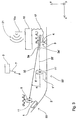
- Fig. 2
- ein Blockdiagramm, das die Funktionsweise der vorliegenden Erfindung darstellt.
- Fig. 3
- ein schematisches Diagramm, das das Einstellen eins Neigungswinkels eines Rotationslasers gemäß einem bevorzugten Ausführungsbeispiel der Erfindung zeigt.
- Fig. 4 und 5
- zwei Neigungsstellungen der Lichtebene, die das Einstellen eines Neigungswinkels eines Rotationslasers gemäß dem bevorzugten Ausführungsbeispiel verdeutlichen sollen.
- Fig. 1
- is a schematic diagram showing the present invention in an exemplary construction project.
- Fig. 2
- a block diagram illustrating the operation of the present invention.
- Fig. 3
- is a schematic diagram showing the setting of an inclination angle of a rotary laser according to a preferred embodiment of the invention.
- 4 and 5
- two inclination positions of the light plane, which are intended to illustrate the setting of an inclination angle of a rotary laser according to the preferred embodiment.
Anhand der Fig. 1 wird nachfolgend ein bevorzugtes Ausführungsbeispiel des erfindungsgemäßen Verfahrens und der erfindungsgemäßen Vorrichtung anhand eines Straßenfertigers näher erläutert.1 is a preferred embodiment of the inventive method and the inventive Device using a paver explained in more detail.
Fig.1 zeigt einen Straßenfertiger bzw. eine Straßenteermaschine
1 beim Teeren einer Straße 2. Ein Teil der Straße
2 ist bereits geteert, der folglich eine bearbeitete Fläche
2a darstellt. Der andere Teil der Straße 2 ist noch nicht
geteert und stellt folglich eine zu bearbeitende Fläche 2b
dar.1 shows a road paver or a road tar machine
1 when tarring a
Gemäß der vorliegenden Erfindung umfaßt die Vorrichtung zum
dreidimensionalen Steuern des Straßenfertigers 1 einen Rotationslaser
3, der entfernt von der Baumaschine an einer vorbestimmten
Position positioniert ist und eine Neigungseinrichtung
4 aufweist. Ferner ist eine erste Empfangseinrichtung
5, wie z. B. ein GPS-Empfänger, an der Baumaschine 1
vorgesehen, die Signale 7a-c dreier Satelliten 9a-c empfängt.
Eine zweite Empfangseinrichtung 11, wie z. B. ein
Laserempfänger, ist an der Baumaschine 1 angebracht und
empfängt ein Höhensignal 13, das von dem Rotationslaser 3
erzeugt wird. Das Höhensignal 13 ist eine Lichtebene 13a,
die durch den rotierenden Laserstrahl erzeugt wird. Eine
Verarbeitungseinrichtung 15 ist in der Nähe des Rotationslasers
3 angeordnet und mit demselben über einen Verbinder
17, wie z. B. ein Kabel, eine Glasfaser oder dergleichen,
verbunden. An der Baumaschine 1 ist ferner eine Übertragungseinrichtung
19, wie z. B. eine Funkantenne, angebracht,
die die Informationen, die durch das empfangene GPS-Signal 7
erhalten werden, mittels eines Übertragungssignals 21 an eine
Antenne 15a der Verarbeitungseinrichtung 15 sendet.According to the present invention, the device for
three-dimensional control of the paver 1 a
Gemäß dem Verfahren wird die Baumaschine 1 derart gesteuert,
daß die Fläche 2a gemäß vorbestimmter Solidaten bearbeitet
wird. Dabei wird eine Ist-Position der Baumaschine 1 aus dem
GPS-Signal 7 und aus dem Höhensignal 13 bestimmt, wie es im
folgenden noch näher beschrieben wird, wobei die Ist-Position
der Baumaschine 1 mit einer Soll-Position verglichen
wird, um gegebenenfalls geeignete Korrektursignale an die
Baumaschine 1 auszugeben, um eine entsprechende Korrektur
der Baumaschine 1 zu bewirken.According to the method, the construction machine 1 is controlled in such a way that
that the
Der Rotationslaser 3 ist ein herkömmlicher rotierender Laser,
der eine Drehachse aufweist, die mittels der Neigungseinrichtung
4 geneigt werden kann. Die Verarbeitungseinrichtung
15 steuert die Neigung des Rotationslasers 3 derart,
daß die Lichtebene 13a an dem Laserempfänger 11 eine
vorbestimmte Referenzhöhe aufweist, wie es bezüglich der
Fig. 3-5 noch näher erläutert wird.The
Der Laserempfänger 11 ist ein linearer Laserempfänger mit
einem höhenlinearen Ausgangssignal, das heißt, daß ein Ausgangssignalpegel
des Laserempfängers 11 direkt proportional
zu dem bestimmten relativen Abstand zu der Referenzhöhe in
vertikaler Richtung ist, so daß besonders bei Ansteuerung
von Proportionalventilen (nicht gezeigt) der Baumaschine 1
ein Vorteil in der Dynamik des Steuerungssystems entsteht.
Der Laserempfänger 11 ist über eine Verbindungsstange 18 an
einer Teeraufbringungsvorrichtung 20 des Straßenfertigers 1
angebracht. Auf diese Weise ist der Laserempfänger 11 für
das Höhensignal 13 ohne weiteres bzw. ohne Abschattungen
durch andere Teile des Straßenfertigers 1 zugänglich. Durch
diese Anbringung ist es ferner gewährleistet, daß sich die
Höhe (z. B. der vertikale Abstand zur Meereshöhe) des Laserempfängers
11 von einer Arbeitshöhe der Teeraufbringungsvorrichtung
20 lediglich um einen konstanten Abstand unterscheidet.
Es wird darauf hingewiesen, daß aus Gründen des
leichteren Verständnisses dieser konstante Abstand, der in
Fig. 4 im wesentlichen der Länge der Verbindungsstange 18
entspricht, vernachlässigt wird, so daß in der weiteren
Beschreibung der Ort des Laserempfängers 11 dem Ort der
Teeraufbringungsvorrichtung 18 bzw. der Baumaschine 1 entsprechen
soll.The
Es wird nun auf Fig. 2 Bezug genommen, die ein Blockdiagramm zeigt, das die Funktionsweise und die Signalverbindungen der vorliegenden Erfindung darstellt.Referring now to Figure 2, this is a block diagram shows that the functioning and the signal connections of the represents the present invention.
Die Verarbeitungseinrichtung 15 empfängt über die Übertragungssignale
21 Informationen von dem GPS-Empfänger 5. Der
GPS-Empfänger 5 berechnet aus dem von den GPS-Sateliten 9
ausgesendeten GPS-Signal 7 zwei Koordinaten der Baumaschine
1 bezüglich zwei Achsen, die dem Längengrad bzw. dem Breitengrad
entsprechen (bezüglich der Horizontalen) und sendet
diese an die Verarbeitungseinrichtung 15. Die Verarbeitungseinrichtung
15 steuert gemäß dieser Koordinaten unter Zuhilfenahme
der vorbestimmten absoluten Position des Rotationslasers
3 und der Solldaten die Neigung des Rotationslasers 3
derart, daß die Laserebene 13a beim Laserempfänger 11 eine
Referenzhöhe aufweist, wie es im folgenden bezugnehmend auf
Fig. 3-5 näher beschrieben wird. Dabei ermittelt die Verarbeitungseinrichtung
15 die Referenzhöhe der Baumaschine 1
aus den Solldaten und den GPS-Koordinaten. Der Laserempfänger
11 empfängt das Höhensignal 13 bzw. die Lichtebene 13a
und sendet an eine Korrektureinrichtung 31 ein Signal, das
der Abweichung der Ist-Höhe der Baumaschine 1 bzw. des Arbeitswerkzeuges
20 von der Referenzhöhe der Lichtebene 13a,
die an dem Laserempfänger vorliegt, entspricht. Obwohl der
Abstand zur Meereshöhe durch den GPS-Empfänger 5 bestimmt
werden könnte bzw. üblicherweise bestimmt wird, wird derselbe
nicht verwendet, da, wie im vorhergehenden erwähnt, die
Genauigkeit dieses Meßwertes zu gering ist.The
Es könnte ferner vorgesehen sein, daß der Laserempfänger 11
mittels der Übertragungseinrichtung 19 (Fig. 1) den vertikalen
Abstand der Baumaschine 1 relativ zu der Referenzhöhe
bzw. die Abweichung der Ist-Höhe von der Referenzhöhe an die
Verarbeitungseinrichtung 15 ausgibt. Die Verarbeitungseinrichtung
15 berechnet aus diesem relativen Abstand und der
Referenzhöhe die dritte Koordinate der Baumaschine 1 bezüglich
einer vertikalen Achse und vergleicht die drei Koordinaten,
d. h. den Längengradwert, den Breitengradwert und die
Höhe, der Baumaschine 1 mit vorbestimmten Sollwerten bzw.
einer Sollfläche.It could also be provided that the
Die Korrektureinrichtung 31 kann beispielsweise eine oder
mehrere Signallampen aufweisen, die einem Fahrer der Baumaschine
1 eventuell vorzunehmende Kurs- bzw. Positionierungsänderungen
anzeigen. Die Korrektureinrichtung 31 kann
ferner mit dem Lenksystem (nicht gezeigt) der Baumaschine 1
verbunden sein, um den Kurs der Baumaschine 1 zu lenken. Bei
dem vorliegenden Ausführungsbeispiel kann die Korrektureinrichtung
31 beispielsweise die Arbeitshöhe einer Teeraufbringungsvorrichtung
32 (Fig. 1) der Straßenteermaschine 1
ändern, um die Arbeitshöhe der Solihöhe anzupassen.The
Anhand der Fig. 3-5 wird das Einstellen des Neigungswinkels
der Drehachse des Rotationslasers 3 gemäß dem bevorzugten
Ausführungsbeispiel beschrieben. Den folgenden Gleichungen
ist ein rechtwinkliges, ortsfestes Koordinatensystem zugrundegelegt,
wobei die x- und y-Achse beispielsweise den Längengrad
bzw. Breitengrad angeben, und die z-Achse die Höhe
bzw. den Abstand zur Meereshöhe angibt. Die verwendeten
Koordinaten sind in einem Gauss-Krüger-Koordinatensystem
festgehalten.3-5 is the setting of the angle of inclination
the axis of rotation of the
Fig. 3 zeigt eine vereinfachte zweidimensionale Darstellung
der vorliegenden Erfindung. Am rechten, unteren Rand der
Darstellung ist das zugrundegelegte rechtwinklige Koordinatensystem
gezeigt, wobei die z-Achse nach oben, die x-Achse
nach links und die y-Achse zum Betrachter hin gerichtet
ist. Es sind zwei Positionen 33, 33' der Baumaschine 1,
1' mit dem Laserempfänger 11, 11' und dem GPS-Empfänger 5,
5' auf der Straße 2 gezeigt, wobei die Position 33' einem
Anfangszustand entspricht und durch gestrichelte Linien dargestellt
ist, wohingegen die augenblickliche Position 33
durch durchgezogene Linien dargestellt ist. Die Verarbeitungseinrichtung
15 ist über den Verbinder 17 mit dem Rotationslaser
3 verbunden, der die Neigungseinrichtung 4 aufweist.
Ein Pfeil 35, 35' stellt den rotierenden Laserstrahl
des Rotationslasers 3 dar, dessen Kopf 3a, 3a' bei jeder
Position 33, 33' der Baumaschine 1, 1' auf den Laserempfänger
11, 11' gerichtet ist. Das Bezugszeichen 9 soll blockhaft
die GPS-Sateliten darstellen, die das GPS-Signal 7 aussenden.3 shows a simplified two-dimensional representation
of the present invention. At the bottom right of the
Representation is the underlying rectangular coordinate system
shown with the z-axis up, the x-axis
to the left and the y-axis directed towards the viewer
is. There are two
Im Ausgangszustand wird durch die Drehung des Rotationslasers
3' ein Laserstrahl 35' parallel zur Straße 2 ausgestrahlt.
Der vom Rotationslaser 3 ausgesendete Laserstrahl
35, 35' dient als Höhenreferenz. Der Kopf 3a, 3a' des Rotationslasers
3 kann mittels der Neigungseinrichtung 4 auf
zwei senkrecht zueinanderstehenden Achsen um die Winkel αx
und αy verdreht werden, wodurch die räumliche Lage der
kreisförmigen Laserebene verändert werden kann, derart, daß
der Rotationslaser 3 jeden Punkt im Raum erreichen kann.In the initial state, the rotation of the rotating laser 3 'emits a laser beam 35' parallel to the
Der Standort (XL, YL, ZL) des Rotationslasers 3 wird zu
Beginn eingemessen. Die aktuellen Ortskoordinaten (XM, YM)
einer sich bewegenden Straßenbaumaschine 1 werden vom GPS-Empfänger
3 ermittelt und über das Übertragungssignal 21 an
die Verarbeitungseinrichtung 15 gesendet. In der Verarbeitungseinrichtung
15 sind die aus dem Bauplan vorgegebenen
Sollhöhen ZS zur jeweiligen Sollkoordinate
Um mit dem Laserstrahl 35 die aus XM und YM ermittelte Sollhöhe
ZS vorzugeben, werden nacheinander die senkrecht zueinander
stehenden Neigungsachsen des Rotationslasers 3 verdreht.
Zuerst wird der Rotationslasers 3 mit der y-Achse als
Drehachse solange um den Winkel αx verdreht, bis dadurch eine
Höhenänderung
In Fig. 4 ist die Neigung der durch den Laserstrahl 35 aufgespannten
Laserebene 13a2, die mit durchgezogenen Linien
dargestellt ist, gegen die mit gestrichelten Linien dargestellte
Laserebene 13a1 im Ausgangszustand gezeigt, wobei
deutlich die resultierende Höhenänderung hx zu sehen ist.4 shows the inclination of the laser plane 13a2 spanned by the
Die Höhenänderung, die die Laserebene 13a aufgrund der Verdrehung
um die y-Achse erfährt, berechnet sich zu:
Falls der Winkel αx lediglich bis zu einem maximal möglichen
Winkel αx,max geändert werden kann und die Höhenänderung hx
mittels der Neigung um die y-Achse um den Winkel αx,max
kleiner als die erforderliche Höhenänderung ZS-ZL ist, wird
die noch bestehende Differenzhöhe
In Fig. 5 ist der Fall dargestellt, daß die Höhenänderung hx der Laserebene 13a2 von Fig. 4 nicht ausreicht, um die erforderliche Höhenänderung ZS-ZL zu bewirken. Aus diesem Grund wird die um die y-Achse geneigte Laserebene 13a2 um die x'-Achse geneigt. Wie es in Fig. 5 ersichtlich ist, wird durch diese zweite Neigung die Differenzhöhe hy bewirkt, so daß die zweimal geneigte Laserebene 13a3 bei den Koordinaten (XM, YM) die Solihöhe ZS vorgibt.5 shows the case in which the change in height hx of the laser plane 13a2 of FIG. 4 is not sufficient to effect the required change in height Z S -Z L. For this reason, the laser plane 13a2 inclined about the y-axis is inclined about the x'-axis. As can be seen in FIG. 5, the difference in height h y is brought about by this second inclination, so that the twice inclined laser plane 13a3 specifies the solid height Z S at the coordinates (X M , Y M ).
Mit der Annahme, daß der Rotationslaser am Ort (XL, YL, ZL)
= (0,0,0) steht, gilt für die Sollhöhe:
Mit dieser Annahme berechnet sich der Neigungswinkel αy
durch die Differenzhöhe
Nach hy aufgelöst ergibt diese Gleichung
Durch Neigung des Rotationslaserkopfs 3 kann auf diese Weise
dem Laserempfänger 11 somit die Referenzhöhe ZS vorgegeben
werden, so daß der Laserempfänger 11 den Abstand zwischen
der Arbeitshöhe der Teeraufbringungsvorrichtung 20 und der
Sollposition bestimmen kann.By tilting the
Es wird darauf hingewiesen, daß bei den im vorhergehenden erwähnten Gleichungen (1) - (4) die aufeinander senkrecht stehenden Drehachsen des Lasersenders YL und XL sind, und daß dieselben nur für den Fall gültig sind, daß YL und XL parallel zu und in Richtung der Gauß-Krüger-Koordinaten Y (Rechtswert) bzw. X (Hochwert) zeigen.It should be noted that in the aforementioned equations (1) - (4) the mutually perpendicular axes of rotation of the laser transmitter are Y L and X L , and that they are only valid in the case that Y L and X L are parallel point to and in the direction of the Gauss-Krüger coordinates Y (right value) and X (high value).
Bezugnehmend auf Gleichung (2) wird auf folgendes hingewiesen:
liegt die Koordinate des Laserempfängers auf der Neigungsachse
YL, so muß der vom Rotationslaser 3 erzeugte Laserstrahl
durch Neigung um die Neigungsachse XL um den Winkel
αx auf den Laserempfänger 11 gerichtet werden. Ist diese
Einstellung mechanisch nicht möglich, da der notwendige Neigungswinkel
αx den maximalen Winkel αx,max überschreitet, so
muß die Neigungsachse um mindestens 90° verdrehbar sein. Analoges
gilt für den Fall, wenn die y-Koordinate des Empfängers
auf der Neigungsachse XL liegt. Ferner kann der Fall,
daß (XL, YL, ZL) = (0,0,0) nicht gilt, als konstanter Offset
betrachtet und leicht auf die obigen Gleichungen (2) - (4)
übertragen werden.With reference to equation (2), the following is pointed out: If the coordinate of the laser receiver lies on the inclination axis Y L , the laser beam generated by the
Obwohl die erste Empfangseinrichtung 5 bei dem bevorzugten
Ausführungsbeispiel als ein GPS-Empfänger dargestellt ist,
kann die erste Empfangseinrichtung 5 ferner zusätzliche Einrichtungen
zum Verbessern der Meßgenauigkeit aufweisen, um
das GPS-Signal auch bei einer Abschattung simulieren zu können.Although the
Der GPS-Empfänger 5 und der Laserempfänger 11 sowie die Korrektueinrichtung
31 und/oder die Übertragungseinrichtung 19
können in einem Paket integriert sein, so daß die Anzahl der
Komponenten in der Baumaschine 1 verringert wird. Entsprechend
kann die Verarbeitungseinrichtung 15 mit dem Rotationslaser
3 einstückig sein, so daß die Anzahl der notwendigen
Komponenten zusätzlich reduziert wird.The
Bei einem weiteren Ausführungsbeispiel der vorliegenden Erfindung wird zum Erzeugen des Höhensignals ein Laser mit einer Dreheinrichtung und einer Neigungseinrichtung verwendet, wobei keine Laserebene aufgespannt wird, sondern ein Laserstrahl immer auf den Laserempfänger und die Solihöhe gerichtet ist. In diesem Fall werden aus der bestimmten absoluten horizontalen Position XM, YM der Baumaschine 1, der vorbestimmten absoluten Position (XL, YL, ZL) der Lasers und der Referenzhöhe ZS(XM, YM) ein Drehwinkel für die Dreheinrichtung und ein Neigungswinkel für die Neigungseinrichtung berechnet.In a further exemplary embodiment of the present invention, a laser with a rotating device and a tilting device is used to generate the height signal, wherein no laser plane is spanned, but a laser beam is always directed onto the laser receiver and the solo height. In this case, the determined absolute horizontal position X M , Y M of the construction machine 1, the predetermined absolute position (X L , Y L , Z L ) of the laser and the reference height ZS (X M , Y M ) become an angle of rotation for the Rotating device and an inclination angle for the inclination device are calculated.
Der Laserempfänger kann ebenfalls ein gewöhnliches mehrkanaliges Laserarray oder eine andere geeignete Einrichtung zum Empfangen des Höhensignals sein.The laser receiver can also be an ordinary multi-channel Laser array or other suitable device to receive the altitude signal.
Die Verarbeitungseinrichtung kann beispielsweise ein Personalcomputer sein, der einen Speicher aufweist, in dem die Sollwerte des Bauvorhabens (Geländeform) gespeichert sind.The processing device can, for example, be a personal computer be, which has a memory in which the Setpoints of the construction project (site shape) are saved.
Claims (19)
wobei die Baumaschine (1) das Höhensignal (13) empfängt und das Arbeitswerkzeug (20) abhängig von dem Höhensignal (13) steuert.
wherein the construction machine (1) receives the height signal (13) and controls the working tool (20) depending on the height signal (13).
wobei die Verarbeitungseinrichtung (15) den ersten Neigungswinkel (αx) aus einer Höhendifferenz (ZS-ZL) zwischen der Solihöhe (ZS) und der Höhenposition (ZL) am stationären Standort des Lasersenders (3) und einem Abstand (XM-XL) zwischen der Baumaschine (1) und dem stationären Standort (XL, YL, ZL) des Lasersenders (3) entlang einer ersten Richtung bestimmt;
wherein the processing device (15) the first inclination angle (α x ) from a height difference (Z S -Z L ) between the solo height (Z S ) and the height position (Z L ) at the stationary location of the laser transmitter (3) and a distance (X M -X L ) between the construction machine (1) and the stationary location (X L , Y L , Z L ) of the laser transmitter (3) along a first direction;
wobei die Empfangseinrichtung (11) ein Signal, das der Abweichung entspricht, an eine Korrektureinrichtung (31) sendet, die das Arbeitswerkzeug (20) der Baumaschine (1) steuert, um die Abweichung von der vorbestimmten Sollposition (ZS) zu kompensieren.Device according to one of Claims 8 to 14, in which the second receiving device (11) determines the deviation of a position of the working tool (20) of the construction machine (1) from a desired position (Z S );
wherein the receiving device (11) sends a signal corresponding to the deviation to a correction device (31) which controls the work tool (20) of the construction machine (1) in order to compensate for the deviation from the predetermined target position (Z S ).
Applications Claiming Priority (2)
| Application Number | Priority Date | Filing Date | Title |
|---|---|---|---|
| DE19940404A DE19940404C2 (en) | 1999-08-25 | 1999-08-25 | Method and device for three-dimensional control of a construction machine |
| DE19940404 | 1999-08-25 |
Publications (2)
| Publication Number | Publication Date |
|---|---|
| EP1079029A2 true EP1079029A2 (en) | 2001-02-28 |
| EP1079029A3 EP1079029A3 (en) | 2004-03-10 |
Family
ID=7919624
Family Applications (1)
| Application Number | Title | Priority Date | Filing Date |
|---|---|---|---|
| EP00118315A Withdrawn EP1079029A3 (en) | 1999-08-25 | 2000-08-23 | Method and apparatus for the three dimensional control of a construction machine |
Country Status (2)
| Country | Link |
|---|---|
| EP (1) | EP1079029A3 (en) |
| DE (1) | DE19940404C2 (en) |
Cited By (15)
| Publication number | Priority date | Publication date | Assignee | Title |
|---|---|---|---|---|
| US6948267B2 (en) | 2001-05-11 | 2005-09-27 | Kalannin Kaspek Oy | Device for optimization of the thickness of an ice layer |
| EP1672122A1 (en) | 2004-12-17 | 2006-06-21 | Leica Geosystems AG | Method and apparatus for controlling a road working machine |
| DE102006009404B3 (en) * | 2006-02-26 | 2007-07-05 | Gräf, Stefan | Arrangement for relative position determination of photoelectric receiver system, has receiver system which consists of equilateral carrier, which is obtuse angled within cross section in form of roof edge prism |
| EP1607717A3 (en) * | 2004-06-15 | 2007-12-19 | Kabushiki Kaisha Topcon | Position measuring system |
| EP1983299A1 (en) * | 2007-04-16 | 2008-10-22 | MOBA - Mobile Automation AG | Apparatus and method for determining an elevation of working tools based on a laser system |
| EP2040030A1 (en) * | 2007-09-24 | 2009-03-25 | Leica Geosystems AG | Positioning method |
| US7510247B2 (en) | 2003-03-17 | 2009-03-31 | Kalannin Kaspek Oy | Ice resurfacing machine as well as system and method for ice maintenance |
| WO2009055955A1 (en) * | 2007-11-01 | 2009-05-07 | Pius Kuster | Method and device for determining an object from hybrid measurements |
| US8794868B2 (en) | 2007-06-21 | 2014-08-05 | Leica Geosystems Ag | Optical guidance system for a laying engine for producing a concrete or asphalt top layer |
| AT517924A1 (en) * | 2015-11-10 | 2017-05-15 | Ing Günther Lehmann Dipl | marking System |
| WO2017152227A1 (en) * | 2016-03-08 | 2017-09-14 | Earley Ross | Laser level checking |
| DE102011054224B4 (en) | 2011-01-24 | 2019-06-19 | Trimble Inc. (n.d.Ges.d.Staates Delaware) | Laser Reference System |
| DE102017012010A1 (en) * | 2017-12-22 | 2019-06-27 | Wirtgen Gmbh | Self-propelled construction machine and method for controlling a self-propelled construction machine |
| CN110004800A (en) * | 2019-04-10 | 2019-07-12 | 安徽开源路桥有限责任公司 | Asphalt concrete pavement construction equipment and construction method based on 3D numerical control system |
| CN113983954A (en) * | 2021-10-19 | 2022-01-28 | 中铁大桥科学研究院有限公司 | Method and device for measuring bridge deck line shape |
Families Citing this family (7)
| Publication number | Priority date | Publication date | Assignee | Title |
|---|---|---|---|---|
| DE102005024676A1 (en) * | 2004-12-21 | 2006-07-06 | Bosch Rexroth Aktiengesellschaft | System for position detection and control for working arms of mobile working machines |
| EP1677125A1 (en) | 2004-12-28 | 2006-07-05 | Leica Geosystems AG | Method and rotative laser for determining a positional information of at least one object |
| US7588088B2 (en) * | 2006-06-13 | 2009-09-15 | Catgerpillar Trimble Control Technologies, Llc | Motor grader and control system therefore |
| DE102007018352A1 (en) * | 2007-04-18 | 2008-10-30 | Wacker Construction Equipment Ag | Floor cutting device with automatic route guidance |
| DE102010060654A1 (en) * | 2010-11-18 | 2012-05-24 | Status Pro Maschinenmesstechnik Gmbh | Method for measuring horizontal surface of component or structure during construction of e.g. crane, involves receiving data transmitted by positioning system by receivers for determining coordinates, and evaluating data by computing device |
| PL2514873T3 (en) | 2011-04-18 | 2014-08-29 | Voegele Ag J | Method and system for applying a paving composition |
| EP2515255A1 (en) | 2011-04-18 | 2012-10-24 | Joseph Vögele AG | Portable reader for identifying a construction site vehicle |
Citations (3)
| Publication number | Priority date | Publication date | Assignee | Title |
|---|---|---|---|---|
| US5375663A (en) * | 1993-04-01 | 1994-12-27 | Spectra-Physics Laserplane, Inc. | Earthmoving apparatus and method for grading land providing continuous resurveying |
| EP0919837A2 (en) * | 1997-11-14 | 1999-06-02 | Kabushiki Kaisha TOPCON | Communication system for surveying instrument |
| EP0950874A2 (en) * | 1998-03-06 | 1999-10-20 | Kabushiki Kaisha TOPCON | Construction equipment control system |
Family Cites Families (2)
| Publication number | Priority date | Publication date | Assignee | Title |
|---|---|---|---|---|
| US5549412A (en) * | 1995-05-24 | 1996-08-27 | Blaw-Knox Construction Equipment Corporation | Position referencing, measuring and paving method and apparatus for a profiler and paver |
| DE19755324A1 (en) * | 1997-12-12 | 1999-06-17 | Michael Dipl Ing Sartori | Controlling place and position of vehicle |
-
1999
- 1999-08-25 DE DE19940404A patent/DE19940404C2/en not_active Expired - Fee Related
-
2000
- 2000-08-23 EP EP00118315A patent/EP1079029A3/en not_active Withdrawn
Patent Citations (3)
| Publication number | Priority date | Publication date | Assignee | Title |
|---|---|---|---|---|
| US5375663A (en) * | 1993-04-01 | 1994-12-27 | Spectra-Physics Laserplane, Inc. | Earthmoving apparatus and method for grading land providing continuous resurveying |
| EP0919837A2 (en) * | 1997-11-14 | 1999-06-02 | Kabushiki Kaisha TOPCON | Communication system for surveying instrument |
| EP0950874A2 (en) * | 1998-03-06 | 1999-10-20 | Kabushiki Kaisha TOPCON | Construction equipment control system |
Cited By (28)
| Publication number | Priority date | Publication date | Assignee | Title |
|---|---|---|---|---|
| US6948267B2 (en) | 2001-05-11 | 2005-09-27 | Kalannin Kaspek Oy | Device for optimization of the thickness of an ice layer |
| US7510247B2 (en) | 2003-03-17 | 2009-03-31 | Kalannin Kaspek Oy | Ice resurfacing machine as well as system and method for ice maintenance |
| EP1607717A3 (en) * | 2004-06-15 | 2007-12-19 | Kabushiki Kaisha Topcon | Position measuring system |
| US7643923B2 (en) | 2004-12-17 | 2010-01-05 | Leica Geosystems Ag | Method and device for monitoring a road processing machine |
| EP1672122A1 (en) | 2004-12-17 | 2006-06-21 | Leica Geosystems AG | Method and apparatus for controlling a road working machine |
| WO2006064062A1 (en) * | 2004-12-17 | 2006-06-22 | Leica Geosystems Ag | Method and device for monitoring a road processing machine |
| DE102006009404B3 (en) * | 2006-02-26 | 2007-07-05 | Gräf, Stefan | Arrangement for relative position determination of photoelectric receiver system, has receiver system which consists of equilateral carrier, which is obtuse angled within cross section in form of roof edge prism |
| EP1983299A1 (en) * | 2007-04-16 | 2008-10-22 | MOBA - Mobile Automation AG | Apparatus and method for determining an elevation of working tools based on a laser system |
| US7760369B2 (en) | 2007-04-16 | 2010-07-20 | Moba-Mobile Automation Ag | Apparatus and method for determining an elevation of working tools based on a laser system |
| US8794868B2 (en) | 2007-06-21 | 2014-08-05 | Leica Geosystems Ag | Optical guidance system for a laying engine for producing a concrete or asphalt top layer |
| US8422032B2 (en) | 2007-09-24 | 2013-04-16 | Leica Geosystems Ag | Position determination method |
| AU2008303962B2 (en) * | 2007-09-24 | 2011-03-24 | Leica Geosystems Ag | Position determination method |
| CN101809407B (en) * | 2007-09-24 | 2012-09-05 | 莱卡地球系统公开股份有限公司 | Position determination method |
| WO2009039929A1 (en) * | 2007-09-24 | 2009-04-02 | Leica Geosystems Ag | Position determination method |
| EP2040030A1 (en) * | 2007-09-24 | 2009-03-25 | Leica Geosystems AG | Positioning method |
| WO2009055955A1 (en) * | 2007-11-01 | 2009-05-07 | Pius Kuster | Method and device for determining an object from hybrid measurements |
| DE102011054224B4 (en) | 2011-01-24 | 2019-06-19 | Trimble Inc. (n.d.Ges.d.Staates Delaware) | Laser Reference System |
| AT517924A1 (en) * | 2015-11-10 | 2017-05-15 | Ing Günther Lehmann Dipl | marking System |
| AT517924B1 (en) * | 2015-11-10 | 2019-10-15 | Dipl Ing Guenther Lehmann | marking System |
| WO2017152227A1 (en) * | 2016-03-08 | 2017-09-14 | Earley Ross | Laser level checking |
| CN109154500A (en) * | 2016-03-08 | 2019-01-04 | 斯塔夫控股私人有限公司 | Laser leveling inspection |
| US11280607B2 (en) | 2016-03-08 | 2022-03-22 | Staff Holdings Pty Ltd | Laser level checking |
| DE102017012010A1 (en) * | 2017-12-22 | 2019-06-27 | Wirtgen Gmbh | Self-propelled construction machine and method for controlling a self-propelled construction machine |
| EP3502821B1 (en) * | 2017-12-22 | 2021-03-24 | Wirtgen GmbH | Self-propelled construction machine and method for controlling the same |
| US11029704B2 (en) | 2017-12-22 | 2021-06-08 | Wirtgen Gmbh | Self-propelled construction machine and method for controlling a self-propelled construction machine |
| CN110004800A (en) * | 2019-04-10 | 2019-07-12 | 安徽开源路桥有限责任公司 | Asphalt concrete pavement construction equipment and construction method based on 3D numerical control system |
| CN113983954A (en) * | 2021-10-19 | 2022-01-28 | 中铁大桥科学研究院有限公司 | Method and device for measuring bridge deck line shape |
| CN113983954B (en) * | 2021-10-19 | 2023-08-11 | 中铁大桥科学研究院有限公司 | Method and device for measuring bridge deck line shape |
Also Published As
| Publication number | Publication date |
|---|---|
| DE19940404C2 (en) | 2001-07-12 |
| EP1079029A3 (en) | 2004-03-10 |
| DE19940404A1 (en) | 2001-03-29 |
Similar Documents
| Publication | Publication Date | Title |
|---|---|---|
| DE19940404C2 (en) | Method and device for three-dimensional control of a construction machine | |
| DE102007051198B4 (en) | System and method for automatic adjustment of a working device | |
| EP2193333B1 (en) | Positioning method | |
| AT403066B (en) | METHOD FOR DETERMINING THE DEVIATIONS OF THE ACTUAL LOCATION OF A TRACK SECTION | |
| EP1606965B1 (en) | Method and device for adapting a radio network model to the conditions of a real radio network | |
| DE69635569T2 (en) | Device for determining the local position of a car on a road | |
| DE102012011518B3 (en) | Geodetic objective for position determination system to determine position of e.g. landmarks, has interface formed to output signals for determination of spatial orientation of reflector relative to target point in marking direction | |
| EP3502821A1 (en) | Self-propelled construction machine and method for controlling the same | |
| EP3106899A1 (en) | Referenced vehicle control system | |
| DE102018133693B3 (en) | Procedure for calibrating the alignment of a moving object sensor | |
| DE102004062275A1 (en) | Method and device for determining a calibration parameter of a stereo camera | |
| EP1842077A2 (en) | Method and rotating laser for determining an item of position information of at least one object | |
| EP0796420A1 (en) | Surveying and marking device | |
| EP2511658A1 (en) | Measuring system and method for new point determination | |
| DE10308525A1 (en) | surveying system | |
| DE102006019917A1 (en) | Multi-segmented constructional structure e.g. airplane structure, dimensional stability securing method, involves detecting positions of segments and built-together group of segments within coordinate system during assembling structure | |
| EP0858931A2 (en) | Device for controlling the aiming of vehicle headlights | |
| DE102007034354A1 (en) | Method and apparatus for estimating behavior of a vehicle using GPS signals | |
| EP2603767A1 (en) | Method for calibrating a measurement system and device for carrying out the method | |
| EP3839146A1 (en) | Method for milling traffic surfaces with a milling roller, and milling machine for carrying out the method for milling traffic surfaces | |
| DE19544112A1 (en) | Generating digital terrain models, e.g. for agricultural cost optimisation, forestry, construction or cartography | |
| DE102007049123A1 (en) | Marking and / or leveling device and method | |
| EP2998699B1 (en) | Device for providing a height reference for a tool of a construction machine, device and method for adjusting the height of a tool of a construction machine, construction machine | |
| EP1408344B1 (en) | Survey apparatus and survey method using a laserscanner | |
| DE102011054224B4 (en) | Laser Reference System |
Legal Events
| Date | Code | Title | Description |
|---|---|---|---|
| PUAI | Public reference made under article 153(3) epc to a published international application that has entered the european phase |
Free format text: ORIGINAL CODE: 0009012 |
|
| 17P | Request for examination filed |
Effective date: 20000823 |
|
| AK | Designated contracting states |
Kind code of ref document: A2 Designated state(s): AT BE CH CY DE DK ES FI FR GB GR IE IT LI LU MC NL PT SE |
|
| AX | Request for extension of the european patent |
Free format text: AL;LT;LV;MK;RO;SI |
|
| PUAL | Search report despatched |
Free format text: ORIGINAL CODE: 0009013 |
|
| AK | Designated contracting states |
Kind code of ref document: A3 Designated state(s): AT BE CH CY DE DK ES FI FR GB GR IE IT LI LU MC NL PT SE |
|
| AX | Request for extension of the european patent |
Extension state: AL LT LV MK RO SI |
|
| RIC1 | Information provided on ipc code assigned before grant |
Ipc: 7G 01S 17/66 B Ipc: 7E 02F 3/84 B Ipc: 7E 01C 19/00 B Ipc: 7E 02F 9/20 A |
|
| STAA | Information on the status of an ep patent application or granted ep patent |
Free format text: STATUS: THE APPLICATION HAS BEEN WITHDRAWN |
|
| 18W | Application withdrawn |
Effective date: 20040330 |