EP1075074A2 - Gas transfer machine - Google Patents
Gas transfer machine Download PDFInfo
- Publication number
- EP1075074A2 EP1075074A2 EP00116875A EP00116875A EP1075074A2 EP 1075074 A2 EP1075074 A2 EP 1075074A2 EP 00116875 A EP00116875 A EP 00116875A EP 00116875 A EP00116875 A EP 00116875A EP 1075074 A2 EP1075074 A2 EP 1075074A2
- Authority
- EP
- European Patent Office
- Prior art keywords
- stator
- motor
- motor rotor
- rotor
- gas
- Prior art date
- Legal status (The legal status is an assumption and is not a legal conclusion. Google has not performed a legal analysis and makes no representation as to the accuracy of the status listed.)
- Withdrawn
Links
Images


Classifications
-
- F—MECHANICAL ENGINEERING; LIGHTING; HEATING; WEAPONS; BLASTING
- F04—POSITIVE - DISPLACEMENT MACHINES FOR LIQUIDS; PUMPS FOR LIQUIDS OR ELASTIC FLUIDS
- F04B—POSITIVE-DISPLACEMENT MACHINES FOR LIQUIDS; PUMPS
- F04B39/00—Component parts, details, or accessories, of pumps or pumping systems specially adapted for elastic fluids, not otherwise provided for in, or of interest apart from, groups F04B25/00 - F04B37/00
-
- H—ELECTRICITY
- H02—GENERATION; CONVERSION OR DISTRIBUTION OF ELECTRIC POWER
- H02K—DYNAMO-ELECTRIC MACHINES
- H02K5/00—Casings; Enclosures; Supports
- H02K5/04—Casings or enclosures characterised by the shape, form or construction thereof
- H02K5/12—Casings or enclosures characterised by the shape, form or construction thereof specially adapted for operating in liquid or gas
- H02K5/128—Casings or enclosures characterised by the shape, form or construction thereof specially adapted for operating in liquid or gas using air-gap sleeves or air-gap discs
-
- F—MECHANICAL ENGINEERING; LIGHTING; HEATING; WEAPONS; BLASTING
- F04—POSITIVE - DISPLACEMENT MACHINES FOR LIQUIDS; PUMPS FOR LIQUIDS OR ELASTIC FLUIDS
- F04C—ROTARY-PISTON, OR OSCILLATING-PISTON, POSITIVE-DISPLACEMENT MACHINES FOR LIQUIDS; ROTARY-PISTON, OR OSCILLATING-PISTON, POSITIVE-DISPLACEMENT PUMPS
- F04C18/00—Rotary-piston pumps specially adapted for elastic fluids
-
- F—MECHANICAL ENGINEERING; LIGHTING; HEATING; WEAPONS; BLASTING
- F04—POSITIVE - DISPLACEMENT MACHINES FOR LIQUIDS; PUMPS FOR LIQUIDS OR ELASTIC FLUIDS
- F04C—ROTARY-PISTON, OR OSCILLATING-PISTON, POSITIVE-DISPLACEMENT MACHINES FOR LIQUIDS; ROTARY-PISTON, OR OSCILLATING-PISTON, POSITIVE-DISPLACEMENT PUMPS
- F04C29/00—Component parts, details or accessories of pumps or pumping installations, not provided for in groups F04C18/00 - F04C28/00
- F04C29/0042—Driving elements, brakes, couplings, transmissions specially adapted for pumps
- F04C29/0085—Prime movers
-
- H—ELECTRICITY
- H02—GENERATION; CONVERSION OR DISTRIBUTION OF ELECTRIC POWER
- H02K—DYNAMO-ELECTRIC MACHINES
- H02K3/00—Details of windings
- H02K3/44—Protection against moisture or chemical attack; Windings specially adapted for operation in liquid or gas
-
- F—MECHANICAL ENGINEERING; LIGHTING; HEATING; WEAPONS; BLASTING
- F04—POSITIVE - DISPLACEMENT MACHINES FOR LIQUIDS; PUMPS FOR LIQUIDS OR ELASTIC FLUIDS
- F04C—ROTARY-PISTON, OR OSCILLATING-PISTON, POSITIVE-DISPLACEMENT MACHINES FOR LIQUIDS; ROTARY-PISTON, OR OSCILLATING-PISTON, POSITIVE-DISPLACEMENT PUMPS
- F04C2220/00—Application
- F04C2220/10—Vacuum
-
- F—MECHANICAL ENGINEERING; LIGHTING; HEATING; WEAPONS; BLASTING
- F04—POSITIVE - DISPLACEMENT MACHINES FOR LIQUIDS; PUMPS FOR LIQUIDS OR ELASTIC FLUIDS
- F04C—ROTARY-PISTON, OR OSCILLATING-PISTON, POSITIVE-DISPLACEMENT MACHINES FOR LIQUIDS; ROTARY-PISTON, OR OSCILLATING-PISTON, POSITIVE-DISPLACEMENT PUMPS
- F04C2240/00—Components
- F04C2240/50—Bearings
- F04C2240/51—Bearings for cantilever assemblies
Landscapes
- Engineering & Computer Science (AREA)
- Mechanical Engineering (AREA)
- General Engineering & Computer Science (AREA)
- Power Engineering (AREA)
- Synchronous Machinery (AREA)
- Structures Of Non-Positive Displacement Pumps (AREA)
- Connection Of Motors, Electrical Generators, Mechanical Devices, And The Like (AREA)
- Compressor (AREA)
- Permanent Magnet Type Synchronous Machine (AREA)
- Iron Core Of Rotating Electric Machines (AREA)
- Motor Or Generator Frames (AREA)
Abstract
Description
- The present invention relates to a gas transfer machine for use as a fan, a vacuum pump, a compressor, or the like for transferring a gas based on the rotation of a rotor, and more particularly to a motor for rotating such a rotor.
- FIGS. 1 and 2 of the accompanying drawings show a conventional gas transfer machine for use as a fan, a vacuum pump, a compressor, or the like for transferring a gas. As shown in FIGS. 1 and 2, the conventional gas transfer machine has an induction motor for rotating a rotatable member such as an impeller. Specifically, the conventional gas transfer machine includes a pump rotor 1, a
motor rotor 7 directly coupled to the pump rotor 1 by amain shaft 2, and astator 6 disposed around themotor rotor 7 and havingwindings 8. When themotor rotor 7 is rotated by a revolving magnetic field generated by thestator 6, the pump rotor 1 is rotated to transfer a gas from agas inlet 30 to agas outlet 31. Themain shaft 2 is rotatably supported bybearings stator 6 is covered with acan 11 that comprises a thin sheet of metal. The can 11 fully shields thestator 6 for protection against exposure to the gas, which may be corrosive, that may possibly be introduced through thebearing 3b. Themotor rotor 7 and thestator 6 make up an induction motor. Themotor rotor 7 hassecondary conductors 9 in the form of conductive rods of aluminum or the like andend rings 10 joining the ends of thesecondary conductors 9. - The conventional gas transfer machine shown in FIGS. 1 and 2 suffers the following problems: While the vacuum pump or compressor as the gas transfer machine is in operation, the gas discharged therefrom is heated when compressed, thereby heating the pump rotor to a high temperature. As a result, the motor rotor that is directly connected to the main shaft is also heated to a high temperature. Since the motor rotor rotates at a high speed, its mechanical strength needs to be taken into account for reliable operation thereof. Such a requirement makes it difficult to design the motor rotor to rotate at a higher speed. However, there is a demand for vacuum pumps and compressors whose motor rotors rotate at higher speeds for higher performance.
- Since the induction motor has the secondary conductors in its rotor, the end rings and the secondary conductors pose a strength problem when the rotor rotates at high speeds. The end rings and the secondary conductors are also under thermal stresses at high temperatures. Furthermore, the efficiency of the induction motor cannot be increased because of a loss that is necessarily caused by the secondary conductors and the metal can.
- Furthermore, the dimension of coil ends of the induction motor is not minimum because the induction motor usually employs a distributed winding pattern. Consequently, the motor has relatively large dimensions, which make the overall size of the gas transfer machine large.
- Another problem of the induction motor is that it causes slippage. The actual rotational speed of the rotor of the induction motor cannot be determined from a power supply system, but needs to be detected by a sensor or the like coupled with the rotor.
- The motor rotor that is held in contact with the gas being transferred comprises a composite material of electromagnetic sheet steel and aluminum. Therefore, if the gas being transferred is corrosive, then the motor rotor would be corroded. It is necessary to apply a corrosion-resistant coating to the motor rotor or cover the motor rotor with a can. However, the corrosion-resistant coating on the composite material of electromagnetic sheet steel and aluminum is not reliable and tends to be peeled off easily. The can that covers the motor rotor reduces the efficiency because it widens the gap between the motor rotor and the stator.
- It is therefore an object of the present invention to provide a gas transfer machine which is of a compact structure, is stable in operation even when handling a corrosive gas, and can operate at a high speed.
- According to the present invention, there is provided a gas transfer machine comprising a pump rotor mounted on a rotatable shaft for transferring a gas, and a reluctance-type motor for rotating the rotatable shaft about its own axis, the reluctance-type motor comprising a stator, a motor rotor surrounded by the stator, and a shield member isolating the stator from the motor rotor, the motor rotor being directly coupled to the rotatable shaft and having a plurality of magnetic salient poles.
- Since the reluctance-type motor has no secondary conductors and end rings on the motor rotor, the motor rotor is of increased mechanical strength upon rotation at a high speed, and has increased efficiency as it causes no current loss. The stator can have concentrated windings on salient poles for minimizing coil ends and hence for reducing the size of the motor.
- The shield member may comprise a molded body of synthetic resin having a surface positioned radially inwardly of an inner circumferential surface of the stator, the stator being embedded in the molded body of synthetic resin. The stator can thus be protected by the shield member against contact with the gas, which may be corrosive, so that windings of the stator can be protected. In addition, the molded body of synthetic resin causes no eddy current loss.
- Alternatively, the shield member may comprise a can of synthetic resin or nonconductive material. The can of synthetic resin or nonconductive material is also effective to protect the stator and its windings against contact with the gas, which may be corrosive, and causes no current loss.
- The motor rotor may have a plurality of permanent magnets disposed respectively in the magnetic salient poles. The permanent magnets in the magnetic salient poles can increase the torque generated by the motor with an increased output power thereof.
- The motor rotor is preferably made of permalloy. The motor rotor of permally is resistant to corrosion due to contact with the gas, which may be corrosive, and also provides desired magnetic properties for the motor.
- The above and other objects, features, and advantages of the present invention will become apparent from the following description when taken in conjunction with the accompanying drawings which illustrate preferred embodiments of the present invention by way of example.
-
- FIG. 1 is an axial cross-sectional view of a conventional gas transfer machine;
- FIG. 2 is a cross-sectional view taken along line II - II of FIG. 1;
- FIG. 3 is an axial cross-sectional view of a gas transfer machine according to a first embodiment of the present invention;
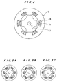
- FIG. 4 is a cross-sectional view taken along line IV - IV of FIG. 3;
- FIGS. 5A, 5B, and 5C are cross-sectional views illustrative of the principle of operation of a reluctance-type motor shown in FIG. 4;
- FIG. 6 is a cross-sectional view of a modification of the reluctance-type motor shown in FIG. 4; and
- FIG. 7 is an axial cross-sectional view of a gas transfer machine according to a second embodiment of the present invention.
-
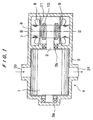
- FIGS. 3 and 4 show a vacuum pump as a gas transfer machine according to a first embodiment of the present invention. As shown in FIG. 3, the vacuum pump has a pump rotor 1 and a
motor rotor 7 directly coupled to the pump rotor 1 by amain shaft 2, and astator 6 disposed around themotor rotor 7 and having windings 8 (see also FIG. 2). When themotor rotor 7 is rotated by a revolving magnetic field generated by thestator 6, the pump rotor 1 is rotated to transfer a gas from agas inlet 30 to agas outlet 31. Themain shaft 2 is rotatably supported bybearings motor rotor 7 hassalient poles 7a. Themotor rotor 7 and thestator 6 make up a reluctance-type motor in which themotor rotor 7 is free of secondary conductors and end rings. - For increasing the efficiency of the motor, the
stator 6 is embedded in a moldedbody 11A of synthetic resin that has a circular inner surface positioned radially inwardly of the inner circumferential surface of thestator 6. The moldedbody 11A of synthetic resin prevents thewindings 8 and thestator 6 from contacting the gas being transferred. Rather than the moldedbody 11A of synthetic resin, a can of synthetic resin or nonconductive material may be used to cover thestator 6. - As shown in FIG. 4, the
stator 6 has six magnetic poles, and themotor rotor 7 has four salientmagnetic poles 7a. Thewindings 8 comprise concentrated windings on salient poles for minimizing coil ends. The reluctance-type motor operates on the principle that thesalient poles 7a of themotor rotor 7 are attracted by magnetic forces generated by the magnetic poles of thestator 6. - The principle of operation of the reluctance-type motor will be described below with reference to FIGS. 5A, 5B, and 5C. In FIG. 5A, windings around salient poles U1, U2 are energized to produce magnetic poles, magnetic forces generated thereby attract salient poles a, c of the rotor, rotating them toward the respective salient poles U1, U2. When the rotor reaches the angular position shown in FIG. 5B, the windings around the salient poles U1, U2 are deenergized, and windings around salient poles V1, V2 are energized to produce magnetic poles. Magnetic forces generated thereby attract the salient poles a, c of the rotor, rotating them toward the respective salient poles V1, V2, as shown in FIG. 5C. In this manner, the windings of the stator are successively energized and de-energized to rotate the
rotor 7 in synchronism with a revolving magnetic field generated by thestator 6. The rotational speed of therotor 7 can be recognized by measuring the frequency with which the windings of thestator 6 are energized. - The
motor rotor 7 has very high mechanism strength upon rotation at a high speed because it is free of secondary conductors and end rings of aluminum or copper as is the case with an induction motor. Particularly, it is not necessary to take into account the resistance of the conductors to centrifugal forces. The efficiency of the motor is not lowered because no loss is caused by currents flowing through the secondary conductors. In addition, because the windings of thestator 6 comprise concentrated windings on salient poles, it is possible to minimize coil ends, thus reducing the over all size of the vacuum pump. - FIG. 6 shows a modified reluctance-type motor in cross section. The modified reluctance-type motor shown in FIG. 6 has a
motor rotor 7 havingsalient poles 7a that include respectivepermanent magnets 12 disposed therein for producing magnetic forces to increase the output power of the motor. The vacuum pump that incorporates the modified reluctance-type motor is required to rotate at a high speed, and discharges the gas at a high temperature from the gas outlet. Since thepermanent magnets 12 are disposed in the respectivesalient poles 7a, thepermanent magnets 12 are retained with high mechanical strength in themotor rotor 7 for protection against disintegration. Thepermanent magnets 12 held in themotor rotor 7 are effective to produce strong magnetic forces tending to rotate themotor rotor 7 for thereby achieving a large torque with increased efficiency. - The vacuum pump may possibly be used in applications where it needs to transfer corrosive gases. The
motor rotor 7 may be made of iron-nickel magnetic alloy such as permally or the like for resistance to corrosion due to contact with a corrosive gas that is being delivered by the vacuum pump. Since permally is a magnetic alloy of iron and nickel and has high magnetic properties, it can be used as the material of a core, with the nickel making the core highly resistant to corrosion. According to the principles of operation of the reluctance-type motor as described above, themotor rotor 7 of permalloy is able to produce sufficient rotational forces. Therefore, themotor rotor 7 that is exposed to a corrosive gas being delivered by the vacuum pump is both resistant to corrosion and able to provide desired magnetic properties required for the motor. - The
motor rotor 7 of the reluctance-type motor rotates in synchronism with the revolving magnetic field generated by thestator 6. Consequently, the rotational speed of themotor rotor 7 can be recognized by measuring the frequency with which the windings of thestator 6 are energized, and the motor is not required to be combined with a speed sensor or the like for detecting the rotational speed of themotor rotor 7. - The reluctance-type motor according to the present invention is applicable to both a pump having two pump rotors rotatable in synchronism with each other for transferring a gas and a pump having a single pump rotor for transferring a gas.
- The
stator 6 is embedded in the moldedbody 11A of synthetic resin. Alternatively, thestator 6 may be covered with a can of synthetic resin or nonconductive material. Since the moldedbody 11A of synthetic resin or the can of synthetic resin or nonconductive material does not cause an eddy current loss, the efficiency of the motor is increased. - FIG. 7 shows in cross section a gas transfer machine according to a second embodiment of the present invention. As shown in FIG. 7, the gas transfer machine comprises a gas circulating device having a circulating
fan 22 disposed in a hermetically sealedhousing 21. The hermetically sealedhousing 21 is filled with a corrosion-resistant process gas 25 under a predetermined pressure for performing any of various chemical or physical processes. Theprocess gas 25 is circulated in the hermetically sealedhousing 21 by the circulatingfan 22 to perform the desired chemical or physical process. - The circulating
fan 22 in the hermetically sealedhousing 21 is mounted on arotatable shaft 23 whose opposite ends are rotatably supportedrespective bearings housing 21. Amotor rotor 7 is coupled to the end of therotatable shaft 23 which projects from thebearing 24b. - The
motor rotor 7 is surrounded by a stator can 11B that is held against the inner circumferential surface of astator 6 havingwindings 8. The stator can 11B separates astator chamber 13 in which thestator 6 is placed from arotor chamber 14 in which themotor rotor 7 is disposed. The stator can 11B fully isolates thestator chamber 13 from therotor chamber 14 into which the gas being transferred may possibly enter via the bearing 24B. Therefore, thestator 6 is protected from contact with the gas, which may be corrosive. The stator can 11B comprises a thin-walled cylindrical member of synthetic resin. Since the stator can 11B is nonconductive, it causes no eddy current loss. - The gas circulating device shown in FIG. 7 may be incorporated in an excimer laser device, for example. In the excimer laser device, a halogen-base gas such as a highly reactive fluorine gas is supplied as the
process gas 25 to the oscillator of the excimer laser device, and hence needs to be circulated in the excimer laser device. Therefore, themotor rotor 7 is preferably made of permally that is a ferromagnetic material and resistant to corrosion against halogen-base gases. Since themotor rotor 7 is of a unitary structure, it may be coated with a corrosion-resistant layer such as a plated nickel layer that remains highly sticky to themotor rotor 7 for protection against being peeled off. - Alternatively, the
motor rotor 7 may be made of a ferromagnetic material such as electromagnetic soft iron, for example, and plated with nickel. - The principles of the present invention are not limited to the vacuum pump and the gas circulating device, but are also applicable to various gas transfer machines.
- Although certain preferred embodiments of the present invention have been shown and described in detail, it should be understood that various changes and modifications may be made therein without departing from the scope of the appended claims.
Claims (5)
- A gas transfer machine comprising:a pump rotor mounted on a rotatable shaft for transferring a gas; anda reluctance-type motor for rotating said rotatable shaft about its own axis, said reluctance-type motor comprising a stator, a motor rotor surrounded by said stator, and a shield member isolating said stator from said motor rotor, said motor rotor being directly coupled to said rotatable shaft and having a plurality of magnetic salient poles.
- A gas transfer machine according to claim 1, wherein said shield member comprises a molded body of synthetic resin having a surface positioned radially inwardly of an inner circumferential surface of said stator, said stator being embedded in said molded body of synthetic resin.
- A gas transfer machine according to claim 1, wherein said shield member comprises a can of synthetic resin or nonconductive material.
- A gas transfer machine according to claim 1, wherein said motor rotor has a plurality of permanent magnets disposed respectively in said magnetic salient poles.
- A gas transfer machine according to claim 1, wherein said motor rotor is made of permalloy.
Applications Claiming Priority (2)
| Application Number | Priority Date | Filing Date | Title |
|---|---|---|---|
| JP22276199 | 1999-08-05 | ||
| JP11222761A JP2001050161A (en) | 1999-08-05 | 1999-08-05 | Gas transfer machine |
Publications (2)
| Publication Number | Publication Date |
|---|---|
| EP1075074A2 true EP1075074A2 (en) | 2001-02-07 |
| EP1075074A3 EP1075074A3 (en) | 2003-07-02 |
Family
ID=16787498
Family Applications (1)
| Application Number | Title | Priority Date | Filing Date |
|---|---|---|---|
| EP00116875A Withdrawn EP1075074A3 (en) | 1999-08-05 | 2000-08-04 | Gas transfer machine |
Country Status (5)
| Country | Link |
|---|---|
| US (1) | US6700273B1 (en) |
| EP (1) | EP1075074A3 (en) |
| JP (1) | JP2001050161A (en) |
| KR (1) | KR20010049994A (en) |
| TW (1) | TW546444B (en) |
Cited By (10)
| Publication number | Priority date | Publication date | Assignee | Title |
|---|---|---|---|---|
| EP1217214A2 (en) | 2000-12-21 | 2002-06-26 | Ingersoll-Rand European Sales Limited | Compressor and driving motor assembly |
| GB2376505A (en) * | 2001-06-11 | 2002-12-18 | Compair Uk Ltd | Driving screw compressors by switched reluctance drive motors |
| EP1717443A1 (en) * | 2004-02-16 | 2006-11-02 | JTEKT Corporation | Motor-driven pump unit |
| WO2009050126A1 (en) * | 2007-10-17 | 2009-04-23 | Eneftech Innovation Sa | Scroll device for compression or expansion |
| EP2175139A2 (en) | 2008-10-07 | 2010-04-14 | ILMVAC GmbH | Pump assembly with pump unit and drive unit with an electric motor with capsulated motor housing |
| WO2011008182A3 (en) * | 2009-07-13 | 2011-10-20 | Ferhat Daldaban | A drum with a switched reluctance motor |
| RU2498484C2 (en) * | 2011-12-22 | 2013-11-10 | Открытое акционерное общество "АЛНАС" (ОАО "АЛНАС") | Submersible synchronous electric motor |
| EP2698540A1 (en) * | 2012-08-16 | 2014-02-19 | Ebara Corporation | Sealing structure, vacuum pump motor including same sealing structure, and vacuum pump |
| EP2700819A1 (en) * | 2012-08-21 | 2014-02-26 | Ebara Corporation | Vacuum pump motor and vacuum pump including same |
| WO2016079426A3 (en) * | 2014-11-19 | 2016-07-21 | Valeo Systemes De Controle Moteur | Electric supercharger |
Families Citing this family (27)
| Publication number | Priority date | Publication date | Assignee | Title |
|---|---|---|---|---|
| KR20020086391A (en) * | 2002-10-12 | 2002-11-18 | 이은진 | Fully enclosed fluid equipment that transmits power to permanent magnets |
| JP2004201428A (en) * | 2002-12-19 | 2004-07-15 | Matsushita Electric Ind Co Ltd | Motor |
| WO2005039019A1 (en) * | 2003-10-15 | 2005-04-28 | Rigaku Corporation | Actuator |
| JP2005210808A (en) * | 2004-01-21 | 2005-08-04 | Mayekawa Mfg Co Ltd | Permanent magnet embedded type synchronous machine |
| KR20050093003A (en) * | 2004-03-17 | 2005-09-23 | 이재본 | Micro turbine generator |
| CN1797904A (en) * | 2004-12-20 | 2006-07-05 | 晋裕工业股份有限公司 | Convex shaped permanent magnet rotor motor |
| MY138646A (en) * | 2005-02-23 | 2009-07-31 | Panasonic Corp | Motor and electric apparatus equipped with a conductive pin for suppressing electrolytic corrosion |
| DE202005005620U1 (en) * | 2005-04-08 | 2006-08-17 | Hawe Hydraulik Gmbh & Co. Kg | pump unit |
| CN100360805C (en) * | 2005-05-08 | 2008-01-09 | 邵志刚 | Gas rotationally compressing apparatus, liquid rotationally conveying device and gas engine |
| JP2007116767A (en) * | 2005-10-18 | 2007-05-10 | Denso Corp | Fuel pump |
| DE102006032765A1 (en) * | 2006-07-14 | 2008-01-17 | Leybold Vacuum Gmbh | vacuum pump |
| GB0618729D0 (en) * | 2006-09-22 | 2006-11-01 | Hobby Roger B | Flux impulse motor |
| JP2008178225A (en) * | 2007-01-18 | 2008-07-31 | Toyota Motor Corp | Rotating electric machine |
| US20100295319A1 (en) * | 2009-05-21 | 2010-11-25 | Engauge Controls Inc. | Wind turbine |
| JP5962179B2 (en) * | 2012-04-26 | 2016-08-03 | 日本精工株式会社 | motor |
| JP6103883B2 (en) * | 2012-10-26 | 2017-03-29 | アスモ株式会社 | Electric pump |
| CA2836309C (en) * | 2012-12-11 | 2022-03-15 | Mcmaster University | Switched reluctance machine with rotor excitation using permanent magnets |
| JP6124688B2 (en) * | 2013-05-31 | 2017-05-10 | 株式会社荏原製作所 | Motor, pump |
| KR20230048164A (en) | 2013-11-13 | 2023-04-10 | 브룩스 오토메이션 인코퍼레이티드 | Sealed switched reluctance motor |
| KR102383699B1 (en) | 2013-11-13 | 2022-04-06 | 브룩스 오토메이션 인코퍼레이티드 | Method and apparatus for brushless electrical machine control |
| TWI695447B (en) | 2013-11-13 | 2020-06-01 | 布魯克斯自動機械公司 | Transport apparatus |
| WO2015073647A1 (en) | 2013-11-13 | 2015-05-21 | Brooks Automation, Inc. | Sealed robot drive |
| JP6236301B2 (en) * | 2013-11-21 | 2017-11-22 | アスモ株式会社 | Electric pump |
| JP6358699B2 (en) * | 2014-07-15 | 2018-07-18 | 大木製▲薬▼株式会社 | Air purification device |
| JP6593163B2 (en) * | 2015-12-28 | 2019-10-23 | スズキ株式会社 | Rotating electric machine |
| KR102044997B1 (en) | 2017-11-28 | 2019-11-14 | 박관식 | Clean air generator for pneumatic conveyor system |
| EP4336713A2 (en) * | 2018-07-19 | 2024-03-13 | Agilent Technologies, Inc. | Vacuum pumping system having an oil-lubricated vacuum pump |
Family Cites Families (17)
| Publication number | Priority date | Publication date | Assignee | Title |
|---|---|---|---|---|
| US4916346A (en) * | 1987-12-28 | 1990-04-10 | General Electric Company | Composite rotor lamination for use in reluctance hompolar, and permanent magnet machines |
| US4995159A (en) * | 1988-08-15 | 1991-02-26 | Pacific Scientific Company | Method of making an electronically commutated reluctance motor |
| CN1073133C (en) * | 1994-04-27 | 2001-10-17 | 松下电器产业株式会社 | Thermosetting composition, molding material, molded structure, and method of decomposing them |
| US5422525A (en) * | 1994-06-30 | 1995-06-06 | Sundstrand Corporation | Switched reluctance machine having unbalance forces compensation coils |
| US6262510B1 (en) * | 1994-09-22 | 2001-07-17 | Iancu Lungu | Electronically switched reluctance motor |
| EP0733804B1 (en) * | 1995-03-20 | 2002-12-18 | Ebara Corporation | Vacuum pump |
| US5806169A (en) * | 1995-04-03 | 1998-09-15 | Trago; Bradley A. | Method of fabricating an injected molded motor assembly |
| US5663605A (en) * | 1995-05-03 | 1997-09-02 | Ford Motor Company | Rotating electrical machine with electromagnetic and permanent magnet excitation |
| EP0846364B1 (en) * | 1995-08-24 | 1999-12-15 | Sulzer Electronics AG | Electric motor |
| CA2190697C (en) | 1996-01-31 | 2000-07-25 | Donald Glenn Larson | Blower motor with adjustable timing |
| JP3690616B2 (en) * | 1996-04-15 | 2005-08-31 | 日立金属株式会社 | Rotating machine |
| US5929541A (en) * | 1996-11-26 | 1999-07-27 | Kinsiro Naito | Synchronous machine |
| JPH10288191A (en) | 1997-04-16 | 1998-10-27 | Daikin Ind Ltd | Pump |
| US6087751A (en) * | 1997-07-01 | 2000-07-11 | Kabushiki Kaisha Toshiba | Reluctance type rotating machine with permanent magnets |
| JP3425369B2 (en) * | 1997-09-24 | 2003-07-14 | 東芝テック株式会社 | 3 phase motor |
| JPH11166500A (en) * | 1997-12-03 | 1999-06-22 | Toshiba Ave Co Ltd | Pump |
| US6247906B1 (en) * | 1999-05-28 | 2001-06-19 | Joseph M. Pijanowski | Combined pump and motor device |
-
1999
- 1999-08-05 JP JP11222761A patent/JP2001050161A/en active Pending
-
2000
- 2000-08-04 EP EP00116875A patent/EP1075074A3/en not_active Withdrawn
- 2000-08-04 KR KR1020000045235A patent/KR20010049994A/en not_active Application Discontinuation
- 2000-08-04 US US09/633,139 patent/US6700273B1/en not_active Expired - Fee Related
- 2000-08-04 TW TW089115668A patent/TW546444B/en not_active IP Right Cessation
Non-Patent Citations (1)
| Title |
|---|
| None |
Cited By (19)
| Publication number | Priority date | Publication date | Assignee | Title |
|---|---|---|---|---|
| EP1217214B1 (en) * | 2000-12-21 | 2008-08-06 | Ingersoll-Rand European Sales Limited | Compressor and driving motor assembly |
| US7573165B2 (en) | 2000-12-21 | 2009-08-11 | Ingersoll-Rand European Sales Limited | Compressor and driving motor assembly |
| EP1217214A2 (en) | 2000-12-21 | 2002-06-26 | Ingersoll-Rand European Sales Limited | Compressor and driving motor assembly |
| GB2376505A (en) * | 2001-06-11 | 2002-12-18 | Compair Uk Ltd | Driving screw compressors by switched reluctance drive motors |
| GB2376505B (en) * | 2001-06-11 | 2003-12-17 | Compair Uk Ltd | Improvements in screw compressors |
| EP1717443A1 (en) * | 2004-02-16 | 2006-11-02 | JTEKT Corporation | Motor-driven pump unit |
| EP1717443A4 (en) * | 2004-02-16 | 2010-10-20 | Jtekt Corp | Motor-driven pump unit |
| EP2204531A1 (en) * | 2007-10-17 | 2010-07-07 | Eneftech Innovation SA | Scroll device for compression or expansion |
| WO2009050126A1 (en) * | 2007-10-17 | 2009-04-23 | Eneftech Innovation Sa | Scroll device for compression or expansion |
| DE102008042656A1 (en) | 2008-10-07 | 2010-04-15 | Ilmvac Gmbh | Electric motor with encapsulated motor housing |
| EP2175139A2 (en) | 2008-10-07 | 2010-04-14 | ILMVAC GmbH | Pump assembly with pump unit and drive unit with an electric motor with capsulated motor housing |
| WO2011008182A3 (en) * | 2009-07-13 | 2011-10-20 | Ferhat Daldaban | A drum with a switched reluctance motor |
| RU2498484C2 (en) * | 2011-12-22 | 2013-11-10 | Открытое акционерное общество "АЛНАС" (ОАО "АЛНАС") | Submersible synchronous electric motor |
| EP2698540A1 (en) * | 2012-08-16 | 2014-02-19 | Ebara Corporation | Sealing structure, vacuum pump motor including same sealing structure, and vacuum pump |
| US9429166B2 (en) | 2012-08-16 | 2016-08-30 | Ebara Corporation | Sealing structure, vacuum pump motor including same sealing structure, and vacuum pump |
| EP2700819A1 (en) * | 2012-08-21 | 2014-02-26 | Ebara Corporation | Vacuum pump motor and vacuum pump including same |
| US9291155B2 (en) | 2012-08-21 | 2016-03-22 | Ebara Corporation | Vacuum pump motor and vacuum pump having balance rings |
| TWI575852B (en) * | 2012-08-21 | 2017-03-21 | 荏原製作所股份有限公司 | Vacuum pump motor and vacuum pump with the vacuum pump motor |
| WO2016079426A3 (en) * | 2014-11-19 | 2016-07-21 | Valeo Systemes De Controle Moteur | Electric supercharger |
Also Published As
| Publication number | Publication date |
|---|---|
| US6700273B1 (en) | 2004-03-02 |
| KR20010049994A (en) | 2001-06-15 |
| EP1075074A3 (en) | 2003-07-02 |
| TW546444B (en) | 2003-08-11 |
| JP2001050161A (en) | 2001-02-23 |
Similar Documents
| Publication | Publication Date | Title |
|---|---|---|
| US6700273B1 (en) | Gas transfer machine | |
| US7709988B2 (en) | Methods and apparatus for using an electrical machine to transport fluids through a pipeline | |
| US7768173B2 (en) | Apparatus for using an electrical machine to transport fluids through a pipeline | |
| EP2314878B1 (en) | Supercharger | |
| EP1826887B1 (en) | Methods and apparatus for using an electrical machine to transport fluids through a pipeline | |
| US6902380B2 (en) | Vacuum pump with pump rotor pairs and permanent magnet motor | |
| US7531932B2 (en) | Power generating system | |
| EP1286446A1 (en) | Permanent magnet rotor and permanent magnet machine | |
| JPH04219496A (en) | Vacuum pump for clean molecular vacuum | |
| JP2003518896A (en) | Thermally protected electrical machine | |
| CA2233998A1 (en) | Rotodynamic machine for the forwarding of a fluid | |
| EP1233189B1 (en) | Magnetic bearing type vacuum pump | |
| EP0018801A1 (en) | Rotary electrical machines | |
| EP0156606B1 (en) | Generator device | |
| JP2000278903A (en) | Motor and its manufacture | |
| EP0773619B1 (en) | Axial-flow induction motor | |
| JPS59138797A (en) | Circulating pump with magnetically supported rotor | |
| JP3592089B2 (en) | Rotating electric machine | |
| JPH01209942A (en) | Permanent magnet rotor | |
| JPH027842A (en) | Rotary machine | |
| FI130001B (en) | An electric turbomachine | |
| JP2003283010A (en) | Gas laser apparatus | |
| JP2001169486A (en) | High-speed servo motor | |
| JP2002349470A (en) | Motor pump | |
| JPH0260456A (en) | Superconducting rotating machine |
Legal Events
| Date | Code | Title | Description |
|---|---|---|---|
| PUAI | Public reference made under article 153(3) epc to a published international application that has entered the european phase |
Free format text: ORIGINAL CODE: 0009012 |
|
| AK | Designated contracting states |
Kind code of ref document: A2 Designated state(s): AT BE CH CY DE DK ES FI FR GB GR IE IT LI LU MC NL PT SE |
|
| AX | Request for extension of the european patent |
Free format text: AL;LT;LV;MK;RO;SI |
|
| PUAL | Search report despatched |
Free format text: ORIGINAL CODE: 0009013 |
|
| AK | Designated contracting states |
Designated state(s): AT BE CH CY DE DK ES FI FR GB GR IE IT LI LU MC NL PT SE |
|
| AX | Request for extension of the european patent |
Extension state: AL LT LV MK RO SI |
|
| RIC1 | Information provided on ipc code assigned before grant |
Ipc: 7F 04D 25/06 B Ipc: 7H 02K 19/10 B Ipc: 7H 02K 19/06 B Ipc: 7H 02K 3/44 B Ipc: 7H 02K 5/128 A |
|
| 17P | Request for examination filed |
Effective date: 20031229 |
|
| AKX | Designation fees paid |
Designated state(s): DE FR GB NL |
|
| 17Q | First examination report despatched |
Effective date: 20040310 |
|
| GRAP | Despatch of communication of intention to grant a patent |
Free format text: ORIGINAL CODE: EPIDOSNIGR1 |
|
| STAA | Information on the status of an ep patent application or granted ep patent |
Free format text: STATUS: THE APPLICATION IS DEEMED TO BE WITHDRAWN |
|
| 18D | Application deemed to be withdrawn |
Effective date: 20061027 |