EP1069862B1 - Guide sleeve for offset vertebrae - Google Patents
Guide sleeve for offset vertebrae Download PDFInfo
- Publication number
- EP1069862B1 EP1069862B1 EP99916588A EP99916588A EP1069862B1 EP 1069862 B1 EP1069862 B1 EP 1069862B1 EP 99916588 A EP99916588 A EP 99916588A EP 99916588 A EP99916588 A EP 99916588A EP 1069862 B1 EP1069862 B1 EP 1069862B1
- Authority
- EP
- European Patent Office
- Prior art keywords
- bone engaging
- guide sleeve
- offset
- tube portion
- tube
- Prior art date
- Legal status (The legal status is an assumption and is not a legal conclusion. Google has not performed a legal analysis and makes no representation as to the accuracy of the status listed.)
- Expired - Lifetime
Links
- 210000000988 bone and bone Anatomy 0.000 claims abstract description 87
- 230000007246 mechanism Effects 0.000 claims description 7
- 238000003780 insertion Methods 0.000 claims description 6
- 230000037431 insertion Effects 0.000 claims description 6
- 238000000034 method Methods 0.000 abstract description 7
- 210000001519 tissue Anatomy 0.000 description 5
- 238000012800 visualization Methods 0.000 description 5
- 230000006378 damage Effects 0.000 description 3
- 238000006073 displacement reaction Methods 0.000 description 3
- 208000014674 injury Diseases 0.000 description 3
- 238000001356 surgical procedure Methods 0.000 description 3
- 208000007103 Spondylolisthesis Diseases 0.000 description 2
- 208000027418 Wounds and injury Diseases 0.000 description 2
- 238000003384 imaging method Methods 0.000 description 2
- 239000007943 implant Substances 0.000 description 2
- 238000012986 modification Methods 0.000 description 2
- 230000004048 modification Effects 0.000 description 2
- RTAQQCXQSZGOHL-UHFFFAOYSA-N Titanium Chemical compound [Ti] RTAQQCXQSZGOHL-UHFFFAOYSA-N 0.000 description 1
- 230000005856 abnormality Effects 0.000 description 1
- 230000004075 alteration Effects 0.000 description 1
- XAGFODPZIPBFFR-UHFFFAOYSA-N aluminium Chemical compound [Al] XAGFODPZIPBFFR-UHFFFAOYSA-N 0.000 description 1
- 229910052782 aluminium Inorganic materials 0.000 description 1
- 239000000560 biocompatible material Substances 0.000 description 1
- 238000001804 debridement Methods 0.000 description 1
- 230000007850 degeneration Effects 0.000 description 1
- 201000010099 disease Diseases 0.000 description 1
- 208000037265 diseases, disorders, signs and symptoms Diseases 0.000 description 1
- 230000004927 fusion Effects 0.000 description 1
- 230000006872 improvement Effects 0.000 description 1
- 210000004705 lumbosacral region Anatomy 0.000 description 1
- 230000001537 neural effect Effects 0.000 description 1
- 230000000149 penetrating effect Effects 0.000 description 1
- 238000002360 preparation method Methods 0.000 description 1
- 230000001737 promoting effect Effects 0.000 description 1
- 230000001681 protective effect Effects 0.000 description 1
- 230000006641 stabilisation Effects 0.000 description 1
- 238000011105 stabilization Methods 0.000 description 1
- 229910001220 stainless steel Inorganic materials 0.000 description 1
- 239000010935 stainless steel Substances 0.000 description 1
- 229910052719 titanium Inorganic materials 0.000 description 1
- 239000010936 titanium Substances 0.000 description 1
- 230000008733 trauma Effects 0.000 description 1
Images


Classifications
-
- A—HUMAN NECESSITIES
- A61—MEDICAL OR VETERINARY SCIENCE; HYGIENE
- A61B—DIAGNOSIS; SURGERY; IDENTIFICATION
- A61B17/00—Surgical instruments, devices or methods, e.g. tourniquets
- A61B17/02—Surgical instruments, devices or methods, e.g. tourniquets for holding wounds open; Tractors
- A61B17/025—Joint distractors
-
- A—HUMAN NECESSITIES
- A61—MEDICAL OR VETERINARY SCIENCE; HYGIENE
- A61B—DIAGNOSIS; SURGERY; IDENTIFICATION
- A61B17/00—Surgical instruments, devices or methods, e.g. tourniquets
- A61B17/16—Bone cutting, breaking or removal means other than saws, e.g. Osteoclasts; Drills or chisels for bones; Trepans
- A61B17/17—Guides or aligning means for drills, mills, pins or wires
- A61B17/1739—Guides or aligning means for drills, mills, pins or wires specially adapted for particular parts of the body
- A61B17/1757—Guides or aligning means for drills, mills, pins or wires specially adapted for particular parts of the body for the spine
-
- A—HUMAN NECESSITIES
- A61—MEDICAL OR VETERINARY SCIENCE; HYGIENE
- A61B—DIAGNOSIS; SURGERY; IDENTIFICATION
- A61B17/00—Surgical instruments, devices or methods, e.g. tourniquets
- A61B17/02—Surgical instruments, devices or methods, e.g. tourniquets for holding wounds open; Tractors
- A61B17/025—Joint distractors
- A61B2017/0256—Joint distractors for the spine
-
- A—HUMAN NECESSITIES
- A61—MEDICAL OR VETERINARY SCIENCE; HYGIENE
- A61B—DIAGNOSIS; SURGERY; IDENTIFICATION
- A61B90/00—Instruments, implements or accessories specially adapted for surgery or diagnosis and not covered by any of the groups A61B1/00 - A61B50/00, e.g. for luxation treatment or for protecting wound edges
- A61B90/06—Measuring instruments not otherwise provided for
- A61B2090/062—Measuring instruments not otherwise provided for penetration depth
Definitions
- the present invention relates generally to surgical procedures for spinal stabilization and more specifically to instrumentation adapted for inserting a spinal implant within the intervertebral disc space between adjacent vertebrae. More particularly, while there may be other applications, the present invention is especially suited for engaging two vertebral bodies that are offset in an anterior-posterior fashion, as in spondylolisthesis, with respect to each other and providing a protected passageway for the movement of instruments and implants therethrough.
- WO-A-95/27321 G. K. Michelson
- WO-A-95/27321 G. K. Michelson
- a common condition in spinal abnormalities is that adjacent vertebral bodies have been displaced creating an anterior-posterior offset condition. While offset vertebral bodies may be encountered in any part of the spine as a result of trauma, disease, or degeneration, the condition of spondylolisthesis typically develops in the lumbar spine.
- the uniform bone engaging end of the hollow sleeve in prior systems fails to completely engage both offset vertebra bodies simultaneously.
- This incomplete engagement with the offset vertebral bodies creates an unprotected space between one of the vertebral bodies and the end of the hollow sleeve.
- This unprotected space may allow contact between instruments disposed within the sleeve, such as cutting instruments, and surrounding tissue. Such contact may damage the sensitive tissue adjacent to the vertebral body leading to potential injury or death for the patient.
- the present invention is directed to this need and provides a more effective protective guide sleeve for engaging offset vertebral bodies.
- the present invention provides a guide sleeve having offset bone engaging portions.
- the sleeve comprises a first tube portion having a first bone engaging end and a second tube portion moveably connected to the first tube portion.
- the second tube portion includes a second bone engaging end disposed proximal to the first bone engaging end.
- the second tube portion is moveable in relation to the first bone engaging portion to create an offset between the second bone engaging surface in relation to the first bone engaging surface.
- the bone engaging end will include a distraction portion extending distally therefrom.
- the guide sleeve may define one or more windows for visualization.
- the invention provides a sleeve composed of a tube having a longitudinal axis and a bone engaging end.
- the bone engaging end has a first bone engaging portion and a second bone engaging portion.
- the second bone engaging portion is offset with respect to the first bone engaging portion.
- the offset bone engaging portions are adapted to engage offset vertebral bodies.
- the present invention is useful with a method of positioning a guide sleeve against a first vertebral body offset from a second vertebral body.
- the method includes making a determination of the amount of offset between the first vertebral body and the second vertebral body.
- a guide sleeve is provided that includes a bone engaging portion with a first portion and a second portion longitudinally offset from the first portion, the offset between the first and second portions substantially corresponding to the offset between the first vertebral body and the second vertebral body.
- the guide sleeve is then positioned adjacent the spine with the first bone engaging portion engaging the first vertebral body and the second bone engaging portion engaging the second vertebral body.
- the guide sleeve may be composed of a first portion slidably connected to a second portion.
- the amount of offset may be adjusted to correspond to the offset between adjacent vertebra.
- the extent of offset between the bone engaging portion may be adjusted after insertion into the body.
- One object of the present invention is to provide an improved guide sleeve for engaging offset bone segments.
- the present invention provides a guide sleeve for guiding instruments to a surgical site and protecting surrounding tissue from injury as a result of contact with the instruments disposed within the sleeve. While the invention may have other applications, particularly in the spine, in one preferred embodiment the invention is specifically adapted to engage anterior-posterior offset vertebral bodies to define a protected access passage to the disc space between the offset vertebral bodies.
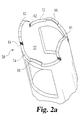
- Figs. 1 and 2 illustrate a guide sleeve in accordance with a preferred embodiment of the invention.
- guide sleeve 50 includes a tube body 52 defining a bone engaging end 58 and an opposite proximal end 59.
- Tube body 52 defines a longitudinal axis 65 extending between bone engaging end 58 and proximal end 59, as well as a longitudinally extending internal working channel 53 (Fig. 2a) adapted to receive surgical instruments.
- tube body 52 defines windows 54 and 56 extending through the tube side walls. Windows 54 and 56 provide access through the tube for external visualization of instruments disposed within the tube, visualization of the disc space and instrument access for debridement.
- Smaller window 54 is offset along longitudinal axis 65 from bone engaging end 58 by side wall portion 76.
- larger window 56 is offset along longitudinal axis 65 from bone engaging end 58 by side wall portion 78.
- Side wall portion 76 is longer than side wall portion 78 and thus provides greater protection against the intrusion of neural tissue into the working channel of guide sleeve 50.
- the bone engaging end includes a pair of opposing distraction extensions 60 and 61 having tapered leading tips to ease insertion into the disc space.
- distraction extension 60 includes offset groove portions 62 and 64 to engage the adjacent vertebral bodies and resist expulsion from the disc space.
- Distraction extension 61 is similarly configured.
- Distraction extension 60 terminates on a first side adjacent bone engaging surface 72 and on a second side adjacent bone engaging surface 74.
- Distraction extension 61 is similarly configured and terminates adjacent bone engaging surfaces 72 and 74.
- bone engaging surfaces 72 and 74 each have a substantially planar configuration interrupted by spikes 66 and 68, respectively.
- distraction extensions 60 and 61 are configured to have the same extent of longitudinal extension (Fig. 2).
- bone engaging surfaces 72 and 74 are longitudinally offset by a distance 70.
- each bone engaging surface 72 and 74 includes a spike 66 and 68, respectively, for penetrating the vertebral bone.
- the tips of spikes 66 and 68 are likewise offset by a distance approximate to distance 70. While spikes have been shown in a preferred embodiment, it is contemplated that spikes are not required to utilize the present invention. Moreover, although one spike has been shown on each surface, those skilled in the art will understand that more or less spikes or other bone engaging structures may be utilized on the bone engaging surfaces without deviating from the invention.
- Bone engagement ends 72 and 74 are offset a distance 70 that is selected to approximate the amount of anterior-posterior displacement between adjacent vertebral bodies. It will be understood that a series of guide sleeves 50 may be provided, each having a different displacement 70, such that the appropriate guide sleeve 50 may be selected depending upon the amount of anterior-posterior offset between adjacent vertebra determined during examination of the vertebral bodies.
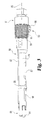
- Guide sleeve 80 includes first end 81 and an opposite bone engaging end 89 and a longitudinal axis 85 extending therebetween.
- Guide sleeve 80 is divided into a fixed portion 82 and a movable portion 84.
- fixed portion 82 and movable portion 84 are configured to define the side walls of a cylindrical tube to thereby form 360 degrees of protection.
- one of the portions may form the complete guide tube with a segment thereof being movable to adjust the configuration of bone engaging end 89.
- the proximal portion of moveable portion 84 is maintained in alignment with fixed portion 82 by adjustment mechanism 83.
- the distal portion of moveable portion 84 is maintained in alignment with fixed portion 82 by distal guide 86.
- Guide sleeve 80 also includes visualization windows 87 and 88 formed in movable portion 84 and an opposing visualization window formed in fixed portion 82.
- the bone engaging end 89 is configured similar to the bone engaging end 58 of guide sleeve 50 previously described. Bone engaging end 89 includes a pair of distraction extensions 94. In the illustrated embodiment, distraction extensions 94 do not include the tapered sections adjacent the distal tip as shown with respect to guide sleeve 50. However, it is contemplated that such a configuration may be used if it is desirable to ease insertion of the distraction extensions into the disc space.
- Fixed portion 82 includes bone engaging surface 91 having a spike 90.
- Moveable portion 84 includes bone engaging surface 93 having a spike 92.
- Adjustment mechanism 83 includes an internally threaded collar 95 rotatably mounted on sleeve 80 by several pins similar to pin 101 engaging an internal shoulder (not shown ⁇ . Collar 95 is adapted to engage external threads 99 disposed on movable sleeve 84. It will be understood that as internally threaded collar 95 is rotated about guide sleeve 80, moveable portion 84 will move axially with respect to fixed portion 82 in relation to the thread pitch. In this manner the offset 102 between bone engaging surfaces 91 and 93 can be adjusted.
- mark 96 on fixed portion 82 and scale 97 on movable portion 82 provides an indication of the amount of displacement between fixed portion 82 and movable portion 84, and the corresponding offset 102 between bone engaging surfaces 91 and 93.
- Collar 95 may be prevented from rotation by use of lock 98 which consists of a threaded shaft (not shown) with an external knob. The threaded shaft is received in a threaded opening in collar 95 and may be advanced to prevent rotation of the collar and thereby securely lock the offset in the desired position.
- an imaging system may be utilized to determine the anterior-posterior offset 102 between adjacent lower vertebral body V 1 and upper vertebral body V 2 .
- a fixed guide sleeve 50 having a longitudinal offset 70 between a lower bone engaging end 74 and an upper bone engaging end 72 approximating offset 102 may be selected or an adjustable guide sleeve 80 may be adjusted to provide a longitudinal offset 102.
- a guide sleeve according the embodiment shown in Figs. 1 and 2 may be used in a similar manner, for the purposes of illustration the following description will be made with specific reference to the embodiment illustrated in Figs. 3 and 4.
- Surgical access to the spine is achieved by known methods.
- the surgical procedure is performed from the posterior side of the spine.
- a distractor with the desired distraction height will be inserted into the disc space D to accomplish distraction.
- Guide sleeve 80 having offset 102 and distraction extensions substantially matching the distractor height is then passed over the distractor and positioned adjacent the spine.
- Force is then applied to proximal end 81, such as by mallet or other instrument if manual force is insufficient, to urge distraction extensions 94 into the disc space and spikes 90 and 92 into vertebral bodies V 1 and V 2 , respectively.
- spikes 90 and 92 will be advanced into the vertebral bodies until at least a portion of bone engaging surfaces 91 and 93 are abuttingly engaged with vertebral bodies V 1 and V 2 , respectively.
- guide sleeve 80 may be adjusted once it is in position in the disc space.
- movable portion 84 would be substantially advanced distally.
- Guide sleeve 80 would be advanced with distraction extensions 94 entering the disc space until contact between spike 92 and vertebra V 2 is achieved.
- Spike 90 would then be in contact with vertebra V 1 .
- the adjustment mechanism may then be locked and force applied to the proximal end 81 of guide sleeve 80 to fully seat the guide sleeve in position.
- Guide sleeves according to the present invention are preferably made of biocompatible materials having sufficient strength to withstand the forces encountered during insertion and use. More preferably, the guide sleeves may be made of stainless steel, titanium, or aluminum. Further, while distraction extensions and spikes have been illustrated in the preferred embodiments, it will be understood that such features are not required and that guide sleeves according to the present invention may be formed without these features. Still further, the teaching of the present invention may be applied to double barrel guide sleeves, typically utilized in anterior procedures, to provide similar advantages for adjusting the bone engaging end of the guide sleeves to accommodate various configurations of the vertebral bodies.
Landscapes
- Health & Medical Sciences (AREA)
- Life Sciences & Earth Sciences (AREA)
- Surgery (AREA)
- General Health & Medical Sciences (AREA)
- Veterinary Medicine (AREA)
- Biomedical Technology (AREA)
- Heart & Thoracic Surgery (AREA)
- Medical Informatics (AREA)
- Molecular Biology (AREA)
- Animal Behavior & Ethology (AREA)
- Nuclear Medicine, Radiotherapy & Molecular Imaging (AREA)
- Public Health (AREA)
- Engineering & Computer Science (AREA)
- Orthopedic Medicine & Surgery (AREA)
- Dentistry (AREA)
- Oral & Maxillofacial Surgery (AREA)
- Prostheses (AREA)
- Surgical Instruments (AREA)
- Mounting, Exchange, And Manufacturing Of Dies (AREA)
- Pharmaceuticals Containing Other Organic And Inorganic Compounds (AREA)
- Turning (AREA)
Abstract
Description
Claims (13)
- A guide sleeve (50) for engaging an upper vertebra (V2) and a lower vertebra (V1) with an anterior-posterior offset therebetween, the guide sleeve comprising a tube (50) having a longitudinal axis (65) and a bone engaging end (58), said bone engaging end having a first bone engaging portion (72) for engaging the upper vertebra (V2) and a second bone engaging portion (74) for engaging the lower vertebra (V1), characterized by said second bone engaging portion (74) being longitudinally offset (70) with respect to said first bone engaging portion (72).
- The guide sleeve of claim 1, wherein said bone engaging end includes a spike (66) for engaging a vertebral body.
- The guide sleeve of claim 1, wherein said bone engaging end further includes extensions (60, 61) for extending into the disc space between two adjacent vertebra.
- The guide sleeve of claim 1, wherein said first bone engaging portion is slidable longitudinally with respect to said second bone engaging portion.
- The guide sleeve of claim 1, wherein said tube comprises:a first tube portion (82) having said first bone engaging end; anda second tube portion (84) movably coupled to said first tube portion, said second tube portion having said second bone engaging end disposed adjacent said first bone engaging end, wherein said second tube portion is movable in relation to said first tube portion to provide said longitudinal offset between the first bone engaging portion and the second bone engaging portion.
- The guide sleeve of claim 5, wherein said first tube portion has an upper surface defining a first window spaced from said first bone engaging end by a first side wall portion having a first longitudinal length, and said second tube portion has a lower surface defining a second window spaced from said second bone engaging end by second side wall portion having a second longitudinal length, said second length greater than said first length.
- The guide sleeve of claim 5, wherein said first bone engaging end includes a first spike (90) for piercing the bone and said second bone engaging portion includes a second spike (92) for piercing the bone.
- The guide sleeve of claim 5 wherein said second bone engaging end includes a pair of opposing distraction extensions (89, 94) adapted for insertion into the disc space.
- The guide sleeve of claim 8, wherein said first tube portion is a lower portion adapted to engage an lower vertebral body and said second tube portion is an upper portion adapted to engage a upper vertebral body.
- The guide sleeve of claim 5, further including an adjustment mechanism (83) disposed between said first tube portion and said second tube portion, said adjustment mechanism adapted to control the longitudinal extent of offset (102) between said first bone engaging end and said second bone engaging end.
- The guide sleeve of claim 10, wherein said second tube portion includes an external thread (99) and said adjustment mechanism (83) includes an internally threaded collar (95) mounted on said first tube portion for controlling the position of said second tube portion with respect to said first tube portion.
- The guide sleeve of claim 5, wherein said first tube portion includes a plurality of index markings (97) and said second tube includes an indicator (96) disposed adjacent said index markings, said indicator cooperable with said index markings to indicate the longitudinal offset between said first bone engaging portion and said second bone engaging portion.
- The guide sleeve of claim 1 wherein said first bone engaging portion is movably interconnected with said second bone engaging portion, said second bone engaging portion movable with respect to said first bone engaging portion to a longitudinally offset position, adapted for engagement with offset vertebra.
Applications Claiming Priority (5)
| Application Number | Priority Date | Filing Date | Title |
|---|---|---|---|
| US8120698P | 1998-04-09 | 1998-04-09 | |
| US81206P | 1998-04-09 | ||
| US287927 | 1999-04-07 | ||
| US09/287,927 US6197033B1 (en) | 1998-04-09 | 1999-04-07 | Guide sleeve for offset vertebrae |
| PCT/US1999/007863 WO1999052447A1 (en) | 1998-04-09 | 1999-04-09 | Guide sleeve for offset vertebrae |
Publications (2)
| Publication Number | Publication Date |
|---|---|
| EP1069862A1 EP1069862A1 (en) | 2001-01-24 |
| EP1069862B1 true EP1069862B1 (en) | 2004-08-11 |
Family
ID=26765327
Family Applications (1)
| Application Number | Title | Priority Date | Filing Date |
|---|---|---|---|
| EP99916588A Expired - Lifetime EP1069862B1 (en) | 1998-04-09 | 1999-04-09 | Guide sleeve for offset vertebrae |
Country Status (9)
| Country | Link |
|---|---|
| US (1) | US6197033B1 (en) |
| EP (1) | EP1069862B1 (en) |
| JP (1) | JP4004735B2 (en) |
| AT (1) | ATE272984T1 (en) |
| AU (1) | AU739027B2 (en) |
| CA (1) | CA2327348C (en) |
| DE (1) | DE69919343T2 (en) |
| ES (1) | ES2226373T3 (en) |
| WO (1) | WO1999052447A1 (en) |
Families Citing this family (86)
| Publication number | Priority date | Publication date | Assignee | Title |
|---|---|---|---|---|
| AU761818C (en) * | 1999-02-04 | 2004-05-27 | Warsaw Orthopedic, Inc. | Methods and instrumentation for vertebral interbody fusion |
| US6491695B1 (en) * | 1999-11-05 | 2002-12-10 | Carl Roggenbuck | Apparatus and method for aligning vertebrae |
| US6478800B1 (en) | 2000-05-08 | 2002-11-12 | Depuy Acromed, Inc. | Medical installation tool |
| US6641582B1 (en) * | 2000-07-06 | 2003-11-04 | Sulzer Spine-Tech Inc. | Bone preparation instruments and methods |
| WO2002003867A2 (en) * | 2000-07-06 | 2002-01-17 | Sulzer Spine-Tech Inc. | Bone preparation instruments |
| US6599291B1 (en) * | 2000-10-20 | 2003-07-29 | Sdgi Holdings, Inc. | Methods and instruments for interbody surgical techniques |
| US6666891B2 (en) | 2000-11-13 | 2003-12-23 | Frank H. Boehm, Jr. | Device and method for lumbar interbody fusion |
| MXPA03004180A (en) | 2000-11-13 | 2004-12-02 | Boehm Frank H Jr | Device and method for lumbar interbody fusion. |
| US6929647B2 (en) * | 2001-02-21 | 2005-08-16 | Howmedica Osteonics Corp. | Instrumentation and method for implant insertion |
| AU2002338527A1 (en) * | 2001-04-30 | 2002-11-11 | Howmedica Osteonics Corp. | Insertion instrument |
| US20030149438A1 (en) * | 2001-04-30 | 2003-08-07 | Howmedica Osteonics Corp. | Insertion instrument |
| US6652533B2 (en) | 2001-09-20 | 2003-11-25 | Depuy Acromed, Inc. | Medical inserter tool with slaphammer |
| US6709439B2 (en) | 2001-10-30 | 2004-03-23 | Depuy Spine, Inc. | Slaphammer tool |
| JP4339698B2 (en) * | 2002-03-11 | 2009-10-07 | ジンマー・スパイン・オースチン・インコーポレイテツド | Instruments and methods for implanting spinal implant devices |
| US7497859B2 (en) * | 2002-10-29 | 2009-03-03 | Kyphon Sarl | Tools for implanting an artificial vertebral disk |
| JP2006517842A (en) | 2003-02-14 | 2006-08-03 | デピュイ スパイン、インコーポレイテッド | Apparatus and method for in situ forming intervertebral fusion |
| US6945974B2 (en) * | 2003-07-07 | 2005-09-20 | Aesculap Inc. | Spinal stabilization implant and method of application |
| US6945975B2 (en) * | 2003-07-07 | 2005-09-20 | Aesculap, Inc. | Bone fixation assembly and method of securement |
| US7621956B2 (en) * | 2003-07-31 | 2009-11-24 | Globus Medical, Inc. | Prosthetic spinal disc replacement |
| US20050080422A1 (en) * | 2003-10-14 | 2005-04-14 | Centerpulse Spine-Tech, Inc. | Instruments for use with implants, and methods |
| US7311712B2 (en) | 2004-02-26 | 2007-12-25 | Aesculap Implant Systems, Inc. | Polyaxial locking screw plate assembly |
| FR2871366A1 (en) | 2004-06-09 | 2005-12-16 | Ceravic Soc Par Actions Simpli | PROSTHETIC EXPANSIBLE BONE IMPLANT |
| DE102004043996B4 (en) * | 2004-09-08 | 2008-04-17 | Aesculap Ag & Co. Kg | Surgical instrument and implant system |
| ATE524121T1 (en) | 2004-11-24 | 2011-09-15 | Abdou Samy | DEVICES FOR PLACING AN ORTHOPEDIC INTERVERTEBRAL IMPLANT |
| US20060217731A1 (en) * | 2005-03-28 | 2006-09-28 | Sdgi Holdings, Inc. | X-ray and fluoroscopic visualization slots |
| US20070055379A1 (en) * | 2005-08-03 | 2007-03-08 | Stone Corbett W | Annular access devices |
| JP4944111B2 (en) | 2005-08-16 | 2012-05-30 | ベンベニュー メディカル, インコーポレイテッド | Spinal distractor |
| WO2008103781A2 (en) | 2007-02-21 | 2008-08-28 | Benvenue Medical, Inc. | Devices for treating the spine |
| US8366773B2 (en) | 2005-08-16 | 2013-02-05 | Benvenue Medical, Inc. | Apparatus and method for treating bone |
| US20070093897A1 (en) * | 2005-10-21 | 2007-04-26 | Stryker Spine (In France) | System and method for fusion cage implantation |
| US20070123903A1 (en) * | 2005-10-31 | 2007-05-31 | Depuy Spine, Inc. | Medical Device installation tool and methods of use |
| US20070191856A1 (en) * | 2006-01-31 | 2007-08-16 | Sdgi Holdings, Inc. | Adjustable height spinal distractor |
| US8377072B2 (en) * | 2006-02-06 | 2013-02-19 | Depuy Spine, Inc. | Medical device installation tool |
| US8303601B2 (en) * | 2006-06-07 | 2012-11-06 | Stryker Spine | Collet-activated distraction wedge inserter |
| EP3195817B1 (en) * | 2006-07-31 | 2023-09-06 | T.A.G. Medical Products Corporation Ltd. | Drill guide useful in arthroscopic bone transplanting procedure |
| US8105382B2 (en) | 2006-12-07 | 2012-01-31 | Interventional Spine, Inc. | Intervertebral implant |
| JP5371107B2 (en) | 2007-02-21 | 2013-12-18 | ベンベニュー メディカル, インコーポレイテッド | Spinal therapy device |
| US8480715B2 (en) * | 2007-05-22 | 2013-07-09 | Zimmer Spine, Inc. | Spinal implant system and method |
| US8900307B2 (en) | 2007-06-26 | 2014-12-02 | DePuy Synthes Products, LLC | Highly lordosed fusion cage |
| EP2471493A1 (en) | 2008-01-17 | 2012-07-04 | Synthes GmbH | An expandable intervertebral implant and associated method of manufacturing the same |
| BRPI0910325A8 (en) | 2008-04-05 | 2019-01-29 | Synthes Gmbh | expandable intervertebral implant |
| WO2009125243A1 (en) * | 2008-04-08 | 2009-10-15 | Vexim | Guide sleeve for accessing a vertebral body and related methods of use |
| WO2009125242A1 (en) | 2008-04-08 | 2009-10-15 | Vexim | Apparatus for restoration of the spine and methods of use thereof |
| US8123785B2 (en) * | 2008-05-08 | 2012-02-28 | Aesculap Implant Systems, Llc | Minimally invasive spinal stabilization system |
| US8535327B2 (en) | 2009-03-17 | 2013-09-17 | Benvenue Medical, Inc. | Delivery apparatus for use with implantable medical devices |
| US9526620B2 (en) | 2009-03-30 | 2016-12-27 | DePuy Synthes Products, Inc. | Zero profile spinal fusion cage |
| US8206394B2 (en) | 2009-05-13 | 2012-06-26 | Depuy Spine, Inc. | Torque limited instrument for manipulating a spinal rod relative to a bone anchor |
| US8764806B2 (en) | 2009-12-07 | 2014-07-01 | Samy Abdou | Devices and methods for minimally invasive spinal stabilization and instrumentation |
| US9393129B2 (en) | 2009-12-10 | 2016-07-19 | DePuy Synthes Products, Inc. | Bellows-like expandable interbody fusion cage |
| WO2011097315A1 (en) | 2010-02-02 | 2011-08-11 | Azadeh Farin | Spine surgery device |
| US9907560B2 (en) | 2010-06-24 | 2018-03-06 | DePuy Synthes Products, Inc. | Flexible vertebral body shavers |
| US8979860B2 (en) | 2010-06-24 | 2015-03-17 | DePuy Synthes Products. LLC | Enhanced cage insertion device |
| EP2588034B1 (en) | 2010-06-29 | 2018-01-03 | Synthes GmbH | Distractible intervertebral implant |
| DE102010035832A1 (en) * | 2010-08-30 | 2012-03-01 | Spontech Spine Intelligence Group Ag | Instrumentation for inserting an implant into an intervertebral disc space |
| US9402732B2 (en) | 2010-10-11 | 2016-08-02 | DePuy Synthes Products, Inc. | Expandable interspinous process spacer implant |
| KR101240378B1 (en) * | 2010-11-12 | 2013-03-11 | 주식회사 위노바 | Apparatus for Guiding Mesh Implant with Arthrodesis |
| JP5847289B2 (en) | 2011-04-07 | 2016-01-20 | ヴェクシム ソシエテアノニム | Expandable orthopedic device |
| WO2012178018A2 (en) | 2011-06-24 | 2012-12-27 | Benvenue Medical, Inc. | Devices and methods for treating bone tissue |
| US8845728B1 (en) | 2011-09-23 | 2014-09-30 | Samy Abdou | Spinal fixation devices and methods of use |
| US20130226240A1 (en) | 2012-02-22 | 2013-08-29 | Samy Abdou | Spinous process fixation devices and methods of use |
| US9198767B2 (en) | 2012-08-28 | 2015-12-01 | Samy Abdou | Devices and methods for spinal stabilization and instrumentation |
| US8882818B1 (en) | 2012-09-24 | 2014-11-11 | Vg Innovations, Llc | Method for deploying a fusion device for sacroiliac joint fusion |
| US9320617B2 (en) | 2012-10-22 | 2016-04-26 | Cogent Spine, LLC | Devices and methods for spinal stabilization and instrumentation |
| US9717601B2 (en) | 2013-02-28 | 2017-08-01 | DePuy Synthes Products, Inc. | Expandable intervertebral implant, system, kit and method |
| US9522070B2 (en) | 2013-03-07 | 2016-12-20 | Interventional Spine, Inc. | Intervertebral implant |
| US9883874B1 (en) * | 2013-03-08 | 2018-02-06 | Vg Innovations, Llc | Tool and method for implanting fusion device into sacroiliac joint |
| US10085783B2 (en) | 2013-03-14 | 2018-10-02 | Izi Medical Products, Llc | Devices and methods for treating bone tissue |
| DE102013004964B4 (en) | 2013-03-22 | 2016-11-03 | Joimax Gmbh | Instrument set and method for inserting a basket into the disc space between two vertebral bodies |
| FR3015221B1 (en) | 2013-12-23 | 2017-09-01 | Vexim | EXPANSIBLE INTRAVERTEBRAL IMPLANT SYSTEM WITH POSTERIOR PEDICULAR FIXATION |
| US11426290B2 (en) | 2015-03-06 | 2022-08-30 | DePuy Synthes Products, Inc. | Expandable intervertebral implant, system, kit and method |
| US10857003B1 (en) | 2015-10-14 | 2020-12-08 | Samy Abdou | Devices and methods for vertebral stabilization |
| US20170367839A1 (en) | 2016-06-23 | 2017-12-28 | VGI Medical, LLC | Method and apparatus for spinal facet fusion |
| CN109688980B (en) | 2016-06-28 | 2022-06-10 | Eit 新兴移植技术股份有限公司 | Expandable and angularly adjustable intervertebral cage with articulation joint |
| CN109688981A (en) | 2016-06-28 | 2019-04-26 | Eit 新兴移植技术股份有限公司 | Distensible, adjustable angle intervertebral cage |
| US10973648B1 (en) | 2016-10-25 | 2021-04-13 | Samy Abdou | Devices and methods for vertebral bone realignment |
| US10744000B1 (en) | 2016-10-25 | 2020-08-18 | Samy Abdou | Devices and methods for vertebral bone realignment |
| US10888433B2 (en) | 2016-12-14 | 2021-01-12 | DePuy Synthes Products, Inc. | Intervertebral implant inserter and related methods |
| US10398563B2 (en) | 2017-05-08 | 2019-09-03 | Medos International Sarl | Expandable cage |
| US11344424B2 (en) | 2017-06-14 | 2022-05-31 | Medos International Sarl | Expandable intervertebral implant and related methods |
| US10940016B2 (en) | 2017-07-05 | 2021-03-09 | Medos International Sarl | Expandable intervertebral fusion cage |
| US11179248B2 (en) | 2018-10-02 | 2021-11-23 | Samy Abdou | Devices and methods for spinal implantation |
| US11446156B2 (en) | 2018-10-25 | 2022-09-20 | Medos International Sarl | Expandable intervertebral implant, inserter instrument, and related methods |
| US11925393B2 (en) * | 2019-06-28 | 2024-03-12 | K2M, Inc. | Pedicle screw rasp system and adjuster |
| US11426286B2 (en) | 2020-03-06 | 2022-08-30 | Eit Emerging Implant Technologies Gmbh | Expandable intervertebral implant |
| US11850160B2 (en) | 2021-03-26 | 2023-12-26 | Medos International Sarl | Expandable lordotic intervertebral fusion cage |
| US11752009B2 (en) | 2021-04-06 | 2023-09-12 | Medos International Sarl | Expandable intervertebral fusion cage |
Family Cites Families (3)
| Publication number | Priority date | Publication date | Assignee | Title |
|---|---|---|---|---|
| US5772661A (en) | 1988-06-13 | 1998-06-30 | Michelson; Gary Karlin | Methods and instrumentation for the surgical correction of human thoracic and lumbar spinal disease from the antero-lateral aspect of the spine |
| US6093207A (en) | 1994-03-18 | 2000-07-25 | Pisharodi; Madhavan | Middle expanded, removable intervertebral disk stabilizer disk |
| DE19510372C1 (en) * | 1995-03-22 | 1996-07-25 | Aesculap Ag | Drilling gauge for surgical drilling instruments with sleeve |
-
1999
- 1999-04-07 US US09/287,927 patent/US6197033B1/en not_active Expired - Lifetime
- 1999-04-09 AT AT99916588T patent/ATE272984T1/en not_active IP Right Cessation
- 1999-04-09 EP EP99916588A patent/EP1069862B1/en not_active Expired - Lifetime
- 1999-04-09 CA CA002327348A patent/CA2327348C/en not_active Expired - Fee Related
- 1999-04-09 WO PCT/US1999/007863 patent/WO1999052447A1/en active IP Right Grant
- 1999-04-09 AU AU34880/99A patent/AU739027B2/en not_active Ceased
- 1999-04-09 ES ES99916588T patent/ES2226373T3/en not_active Expired - Lifetime
- 1999-04-09 JP JP2000543063A patent/JP4004735B2/en not_active Expired - Fee Related
- 1999-04-09 DE DE69919343T patent/DE69919343T2/en not_active Expired - Fee Related
Also Published As
| Publication number | Publication date |
|---|---|
| AU739027B2 (en) | 2001-10-04 |
| EP1069862A1 (en) | 2001-01-24 |
| ATE272984T1 (en) | 2004-08-15 |
| JP2002511299A (en) | 2002-04-16 |
| JP4004735B2 (en) | 2007-11-07 |
| CA2327348A1 (en) | 1999-10-21 |
| ES2226373T3 (en) | 2005-03-16 |
| DE69919343T2 (en) | 2005-08-11 |
| WO1999052447A1 (en) | 1999-10-21 |
| US6197033B1 (en) | 2001-03-06 |
| AU3488099A (en) | 1999-11-01 |
| CA2327348C (en) | 2007-07-17 |
| DE69919343D1 (en) | 2004-09-16 |
Similar Documents
| Publication | Publication Date | Title |
|---|---|---|
| EP1069862B1 (en) | Guide sleeve for offset vertebrae | |
| US7722618B2 (en) | Method and instrumentation for posterior interbody fusion | |
| US6524318B1 (en) | Spinal surgery instruments and methods | |
| US8840621B2 (en) | Spinal access systems and methods | |
| US6428541B1 (en) | Method and instrumentation for vertebral interbody fusion | |
| US7244258B2 (en) | Methods and instrumentation for vertebral interbody fusion | |
| US6059790A (en) | Apparatus and method for spinal stabilization | |
| US6575981B1 (en) | Methods and instrumentation for vertebral interbody fusion | |
| EP1622525B1 (en) | System for minimally invasive posterior fixation | |
| US8597299B2 (en) | Instrumentation and method for providing surgical access to a spine | |
| US7776046B2 (en) | Method and instrumentation for vertebral interbody fusion | |
| US6743234B2 (en) | Methods and instrumentation for vertebral interbody fusion | |
| US6113602A (en) | Posterior spinal instrument guide and method | |
| AU3744699A (en) | Method and instrumentation for vertebral interbody fusion | |
| KR19980702563A (en) | Methods and instruments for surgical correction of human thoracic and lumbar spine diseases from the outside of the spine | |
| WO2009094493A2 (en) | Spinal access systems and methods | |
| DE10003051C2 (en) | Instruments for lumbar spine surgery |
Legal Events
| Date | Code | Title | Description |
|---|---|---|---|
| PUAI | Public reference made under article 153(3) epc to a published international application that has entered the european phase |
Free format text: ORIGINAL CODE: 0009012 |
|
| 17P | Request for examination filed |
Effective date: 20001107 |
|
| AK | Designated contracting states |
Kind code of ref document: A1 Designated state(s): AT BE CH CY DE DK ES FI FR GB GR IE IT LI LU MC NL PT SE |
|
| GRAP | Despatch of communication of intention to grant a patent |
Free format text: ORIGINAL CODE: EPIDOSNIGR1 |
|
| GRAS | Grant fee paid |
Free format text: ORIGINAL CODE: EPIDOSNIGR3 |
|
| GRAA | (expected) grant |
Free format text: ORIGINAL CODE: 0009210 |
|
| AK | Designated contracting states |
Kind code of ref document: B1 Designated state(s): AT BE CH CY DE DK ES FI FR GB GR IE IT LI LU MC NL PT SE |
|
| PG25 | Lapsed in a contracting state [announced via postgrant information from national office to epo] |
Ref country code: NL Free format text: LAPSE BECAUSE OF FAILURE TO SUBMIT A TRANSLATION OF THE DESCRIPTION OR TO PAY THE FEE WITHIN THE PRESCRIBED TIME-LIMIT Effective date: 20040811 Ref country code: FI Free format text: LAPSE BECAUSE OF FAILURE TO SUBMIT A TRANSLATION OF THE DESCRIPTION OR TO PAY THE FEE WITHIN THE PRESCRIBED TIME-LIMIT Effective date: 20040811 Ref country code: AT Free format text: LAPSE BECAUSE OF FAILURE TO SUBMIT A TRANSLATION OF THE DESCRIPTION OR TO PAY THE FEE WITHIN THE PRESCRIBED TIME-LIMIT Effective date: 20040811 |
|
| REG | Reference to a national code |
Ref country code: GB Ref legal event code: FG4D |
|
| REG | Reference to a national code |
Ref country code: CH Ref legal event code: EP |
|
| REG | Reference to a national code |
Ref country code: IE Ref legal event code: FG4D |
|
| REF | Corresponds to: |
Ref document number: 69919343 Country of ref document: DE Date of ref document: 20040916 Kind code of ref document: P |
|
| REG | Reference to a national code |
Ref country code: GR Ref legal event code: EP Ref document number: 20040402886 Country of ref document: GR |
|
| REG | Reference to a national code |
Ref country code: CH Ref legal event code: NV Representative=s name: RITSCHER & PARTNER AG |
|
| PG25 | Lapsed in a contracting state [announced via postgrant information from national office to epo] |
Ref country code: SE Free format text: LAPSE BECAUSE OF FAILURE TO SUBMIT A TRANSLATION OF THE DESCRIPTION OR TO PAY THE FEE WITHIN THE PRESCRIBED TIME-LIMIT Effective date: 20041111 Ref country code: DK Free format text: LAPSE BECAUSE OF FAILURE TO SUBMIT A TRANSLATION OF THE DESCRIPTION OR TO PAY THE FEE WITHIN THE PRESCRIBED TIME-LIMIT Effective date: 20041111 |
|
| NLV1 | Nl: lapsed or annulled due to failure to fulfill the requirements of art. 29p and 29m of the patents act | ||
| REG | Reference to a national code |
Ref country code: ES Ref legal event code: FG2A Ref document number: 2226373 Country of ref document: ES Kind code of ref document: T3 |
|
| PG25 | Lapsed in a contracting state [announced via postgrant information from national office to epo] |
Ref country code: LU Free format text: LAPSE BECAUSE OF NON-PAYMENT OF DUE FEES Effective date: 20050409 Ref country code: CY Free format text: LAPSE BECAUSE OF FAILURE TO SUBMIT A TRANSLATION OF THE DESCRIPTION OR TO PAY THE FEE WITHIN THE PRESCRIBED TIME-LIMIT Effective date: 20050409 |
|
| PG25 | Lapsed in a contracting state [announced via postgrant information from national office to epo] |
Ref country code: IE Free format text: LAPSE BECAUSE OF NON-PAYMENT OF DUE FEES Effective date: 20050411 |
|
| PG25 | Lapsed in a contracting state [announced via postgrant information from national office to epo] |
Ref country code: MC Free format text: LAPSE BECAUSE OF NON-PAYMENT OF DUE FEES Effective date: 20050430 |
|
| ET | Fr: translation filed | ||
| PLBE | No opposition filed within time limit |
Free format text: ORIGINAL CODE: 0009261 |
|
| STAA | Information on the status of an ep patent application or granted ep patent |
Free format text: STATUS: NO OPPOSITION FILED WITHIN TIME LIMIT |
|
| 26N | No opposition filed |
Effective date: 20050512 |
|
| PGFP | Annual fee paid to national office [announced via postgrant information from national office to epo] |
Ref country code: GR Payment date: 20060406 Year of fee payment: 8 |
|
| PGFP | Annual fee paid to national office [announced via postgrant information from national office to epo] |
Ref country code: BE Payment date: 20060425 Year of fee payment: 8 |
|
| PGFP | Annual fee paid to national office [announced via postgrant information from national office to epo] |
Ref country code: GB Payment date: 20070313 Year of fee payment: 9 |
|
| PGFP | Annual fee paid to national office [announced via postgrant information from national office to epo] |
Ref country code: ES Payment date: 20070417 Year of fee payment: 9 |
|
| BERE | Be: lapsed |
Owner name: *SDGI HOLDINGS INC. Effective date: 20070430 |
|
| PG25 | Lapsed in a contracting state [announced via postgrant information from national office to epo] |
Ref country code: PT Free format text: LAPSE BECAUSE OF NON-PAYMENT OF DUE FEES Effective date: 20050111 |
|
| PGFP | Annual fee paid to national office [announced via postgrant information from national office to epo] |
Ref country code: IT Payment date: 20070616 Year of fee payment: 9 |
|
| PG25 | Lapsed in a contracting state [announced via postgrant information from national office to epo] |
Ref country code: BE Free format text: LAPSE BECAUSE OF NON-PAYMENT OF DUE FEES Effective date: 20070430 |
|
| REG | Reference to a national code |
Ref country code: CH Ref legal event code: PCAR Free format text: RITSCHER & PARTNER AG;RESIRAIN 1;8125 ZOLLIKERBERG (CH) |
|
| PG25 | Lapsed in a contracting state [announced via postgrant information from national office to epo] |
Ref country code: GR Free format text: LAPSE BECAUSE OF NON-PAYMENT OF DUE FEES Effective date: 20071102 |
|
| REG | Reference to a national code |
Ref country code: CH Ref legal event code: PUE Owner name: WARSAW ORTHOPEDIC, INC. Free format text: SDGI HOLDINGS, INC.#300 DELAWARE AVENUE, SUITE 508#WILMINGTON, DE 19801 (US) -TRANSFER TO- WARSAW ORTHOPEDIC, INC.#2500 SILVEUS CROSSING#WARSAW, IN 46581 (US) |
|
| GBPC | Gb: european patent ceased through non-payment of renewal fee |
Effective date: 20080409 |
|
| REG | Reference to a national code |
Ref country code: FR Ref legal event code: TP |
|
| REG | Reference to a national code |
Ref country code: ES Ref legal event code: FD2A Effective date: 20080410 |
|
| PG25 | Lapsed in a contracting state [announced via postgrant information from national office to epo] |
Ref country code: GB Free format text: LAPSE BECAUSE OF NON-PAYMENT OF DUE FEES Effective date: 20080409 |
|
| PG25 | Lapsed in a contracting state [announced via postgrant information from national office to epo] |
Ref country code: ES Free format text: LAPSE BECAUSE OF NON-PAYMENT OF DUE FEES Effective date: 20080410 |
|
| PG25 | Lapsed in a contracting state [announced via postgrant information from national office to epo] |
Ref country code: IT Free format text: LAPSE BECAUSE OF NON-PAYMENT OF DUE FEES Effective date: 20080409 |
|
| PGFP | Annual fee paid to national office [announced via postgrant information from national office to epo] |
Ref country code: FR Payment date: 20090406 Year of fee payment: 11 Ref country code: DE Payment date: 20090430 Year of fee payment: 11 |
|
| PGFP | Annual fee paid to national office [announced via postgrant information from national office to epo] |
Ref country code: CH Payment date: 20090430 Year of fee payment: 11 |
|
| REG | Reference to a national code |
Ref country code: CH Ref legal event code: PL |
|
| REG | Reference to a national code |
Ref country code: FR Ref legal event code: ST Effective date: 20101230 |
|
| PG25 | Lapsed in a contracting state [announced via postgrant information from national office to epo] |
Ref country code: LI Free format text: LAPSE BECAUSE OF NON-PAYMENT OF DUE FEES Effective date: 20100430 Ref country code: DE Free format text: LAPSE BECAUSE OF NON-PAYMENT OF DUE FEES Effective date: 20101103 Ref country code: CH Free format text: LAPSE BECAUSE OF NON-PAYMENT OF DUE FEES Effective date: 20100430 |
|
| PG25 | Lapsed in a contracting state [announced via postgrant information from national office to epo] |
Ref country code: FR Free format text: LAPSE BECAUSE OF NON-PAYMENT OF DUE FEES Effective date: 20100430 |