EP1065347B1 - Method for fuel gas moisturization and heating - Google Patents
Method for fuel gas moisturization and heating Download PDFInfo
- Publication number
- EP1065347B1 EP1065347B1 EP00304151A EP00304151A EP1065347B1 EP 1065347 B1 EP1065347 B1 EP 1065347B1 EP 00304151 A EP00304151 A EP 00304151A EP 00304151 A EP00304151 A EP 00304151A EP 1065347 B1 EP1065347 B1 EP 1065347B1
- Authority
- EP
- European Patent Office
- Prior art keywords
- saturator
- fuel gas
- water
- gas
- fuel
- Prior art date
- Legal status (The legal status is an assumption and is not a legal conclusion. Google has not performed a legal analysis and makes no representation as to the accuracy of the status listed.)
- Expired - Lifetime
Links
- 239000002737 fuel gas Substances 0.000 title claims description 78
- 238000010438 heat treatment Methods 0.000 title claims description 38
- 238000000034 method Methods 0.000 title description 8
- XLYOFNOQVPJJNP-UHFFFAOYSA-N water Substances O XLYOFNOQVPJJNP-UHFFFAOYSA-N 0.000 claims description 78
- 239000007789 gas Substances 0.000 claims description 50
- 239000000446 fuel Substances 0.000 claims description 48
- 229920006395 saturated elastomer Polymers 0.000 claims description 29
- 238000011084 recovery Methods 0.000 claims description 21
- 238000009738 saturating Methods 0.000 claims description 2
- 238000011144 upstream manufacturing Methods 0.000 claims description 2
- 239000008236 heating water Substances 0.000 claims 1
- 239000012530 fluid Substances 0.000 description 8
- VNWKTOKETHGBQD-UHFFFAOYSA-N methane Chemical compound C VNWKTOKETHGBQD-UHFFFAOYSA-N 0.000 description 8
- 239000002131 composite material Substances 0.000 description 6
- 238000000605 extraction Methods 0.000 description 5
- 239000007788 liquid Substances 0.000 description 3
- QGZKDVFQNNGYKY-UHFFFAOYSA-N Ammonia Chemical compound N QGZKDVFQNNGYKY-UHFFFAOYSA-N 0.000 description 2
- 239000000203 mixture Substances 0.000 description 2
- 239000003345 natural gas Substances 0.000 description 2
- 238000010521 absorption reaction Methods 0.000 description 1
- 229910021529 ammonia Inorganic materials 0.000 description 1
- 238000009835 boiling Methods 0.000 description 1
- 238000006243 chemical reaction Methods 0.000 description 1
- 238000002485 combustion reaction Methods 0.000 description 1
- 239000000498 cooling water Substances 0.000 description 1
- 230000003247 decreasing effect Effects 0.000 description 1
- 230000008030 elimination Effects 0.000 description 1
- 238000003379 elimination reaction Methods 0.000 description 1
- 239000010687 lubricating oil Substances 0.000 description 1
- 238000004519 manufacturing process Methods 0.000 description 1
- 238000002156 mixing Methods 0.000 description 1
- 230000004048 modification Effects 0.000 description 1
- 238000012986 modification Methods 0.000 description 1
- 230000003020 moisturizing effect Effects 0.000 description 1
- 238000010248 power generation Methods 0.000 description 1
- 238000005507 spraying Methods 0.000 description 1
- 238000009692 water atomization Methods 0.000 description 1
Images


Classifications
-
- F—MECHANICAL ENGINEERING; LIGHTING; HEATING; WEAPONS; BLASTING
- F01—MACHINES OR ENGINES IN GENERAL; ENGINE PLANTS IN GENERAL; STEAM ENGINES
- F01K—STEAM ENGINE PLANTS; STEAM ACCUMULATORS; ENGINE PLANTS NOT OTHERWISE PROVIDED FOR; ENGINES USING SPECIAL WORKING FLUIDS OR CYCLES
- F01K23/00—Plants characterised by more than one engine delivering power external to the plant, the engines being driven by different fluids
- F01K23/02—Plants characterised by more than one engine delivering power external to the plant, the engines being driven by different fluids the engine cycles being thermally coupled
- F01K23/06—Plants characterised by more than one engine delivering power external to the plant, the engines being driven by different fluids the engine cycles being thermally coupled combustion heat from one cycle heating the fluid in another cycle
- F01K23/10—Plants characterised by more than one engine delivering power external to the plant, the engines being driven by different fluids the engine cycles being thermally coupled combustion heat from one cycle heating the fluid in another cycle with exhaust fluid of one cycle heating the fluid in another cycle
- F01K23/106—Plants characterised by more than one engine delivering power external to the plant, the engines being driven by different fluids the engine cycles being thermally coupled combustion heat from one cycle heating the fluid in another cycle with exhaust fluid of one cycle heating the fluid in another cycle with water evaporated or preheated at different pressures in exhaust boiler
-
- Y—GENERAL TAGGING OF NEW TECHNOLOGICAL DEVELOPMENTS; GENERAL TAGGING OF CROSS-SECTIONAL TECHNOLOGIES SPANNING OVER SEVERAL SECTIONS OF THE IPC; TECHNICAL SUBJECTS COVERED BY FORMER USPC CROSS-REFERENCE ART COLLECTIONS [XRACs] AND DIGESTS
- Y02—TECHNOLOGIES OR APPLICATIONS FOR MITIGATION OR ADAPTATION AGAINST CLIMATE CHANGE
- Y02E—REDUCTION OF GREENHOUSE GAS [GHG] EMISSIONS, RELATED TO ENERGY GENERATION, TRANSMISSION OR DISTRIBUTION
- Y02E20/00—Combustion technologies with mitigation potential
- Y02E20/16—Combined cycle power plant [CCPP], or combined cycle gas turbine [CCGT]
Definitions
- the present invention relates to natural gas fired combined cycle power plants and, in particular, to a modified bottoming cycle for fuel gas saturation and heating to increase power output and thermodynamic efficiency.
- Fuel heating is currently implemented in some combined cycle power plants for improving thermal efficiency. Although current fuel heating methods result in plant power output reduction, when heating the fuel above the LP steam temperature, the gain in thermal efficiency as a result of the decreased heat consumption makes fuel heating an economically attractive design option. Two such systems are shown in DE-A-4321081 and EP-A-0 588 392. However, there remains a need for a method and apparatus for achieving a better temperature matching in the HRSG while avoiding power plant output reduction.
- the bottoming cycle design system results in better temperature matching between the hot and cold heat exchange streams below the lowest pressure evaporator temperature by providing a water heating section for fuel gas saturation in parallel with the lower pressure economizer (LP-EC) in the heat recovery steam generator.
- the heat source for fuel gas saturation in the current invention is the gas turbine exhaust gases.
- the increased gas mass flow due to the addition of moisture results in increased power output from the gas and steam turbines.
- Fuel gas saturation is followed by superheating the fuel, preferably with bottom cycle heat sources, resulting in a larger thermal efficiency gain compared to current fuel heating methods. There is a gain in power output compared to no fuel heating, even when heating the fuel to above the LP steam temperature.
- a combined cycle system including a gas turbine, a steam turbine, and a heat recovery steam generator, wherein gas turbine exhaust gas is used in the heat recovery steam generat for generating steam for the steam turbine, said gas turbine exhaust gas flowing from an entry end to an exit end of the heat recovery steam generator, and wherein the system further comprises a fuel gas saturator having an inlet for hot saturator water, an inlet for fuel gas, an outlet for saturated fuel gas, and a saturator water outlet; a saturator water heater; a flow path for flowing saturator water from said saturator water outlet to said saturator heater, said saturator heater being operatively coupled to a heat source in the heat recovery steam generator for heating saturator water conducted thereto, using said heat source, to produce hot saturator water; a flow path for flowing hot saturator water produced by the saturator heater to the hot saturator water inlet of the fuel gas saturator ; a fuel super
- the fuel gas saturator assembly comprises a fuel gas saturator packed column, for saturating and heating fuel gas with heated water received from the first water heater of the HRSG.
- the fuel gas saturator assembly comprises a water inlet for adding water to the fuel gas and a heat exchanger for heating fuel gas saturated with the water input at the water inlet.
- the heat exchanger receives and uses the heated water from the first water heater to heat the fuel gas.
- the fuel superheater heats the saturated fuel gas using a heat recovery steam generator heat source.
- the herein described modified bottoming cycle is applicable in particular to natural gas fire combined cycle applications.
- FIGURE 1 A schematic of a conventional three pressure reheat combined cycle power plant with fuel heating 10 is shown in FIGURE 1.
- This example includes a gas turbine system 12 comprising a combustion system 14 and a gas turbine 16, and a steam turbine system 18 including a high pressure section 20, an intermediate pressure section 22, and one or more low pressure sections 24 with multiple steam admission points at different pressures.
- the low pressure section 24 exhausts into a condenser 26.
- the steam turbine 18 drives the generator 28 which produces electrical power.
- the gas turbine 12, steam turbine system 18, and generator 28 are arranged in tandem, on a single shaft 30.
- the steam turbine system 18 is associated with a multi-pressure HRSG 32 which includes a low pressure economizer (LP-EC), a low pressure evaporator(LP-EV), a high pressure economizer (HP-EC-2), an intermediate pressure economizer (IP-EC), an intermediate pressure evaporator (IP-EV), a low pressure superheater (LP-SH), a final high pressure economizer (HP-EC-1), an intermediate pressure superheater (IP-SH), a high pressure evaporator (HP-EV), a high pressure superheater section (HP-SH-2), a reheater (RH-SH), and a final high pressure superheater section (HP-SH-1).
- LP-EC low pressure economizer
- IP-EC intermediate pressure economizer
- IP-EV intermediate pressure evaporator
- HP-EC-1 low pressure superheater
- HP-EC-1 intermediate pressure superheater
- HP-SH high pressure evaporator
- HP-SH-2
- Condensate is fed from condenser 26 to the HRSG 32 via conduit 34 with the aid of condensate pump 36.
- the condensate subsequently passes through the LP-EC and into the LP-EV.
- steam from the LP-EV is fed to the LP-SH and then returned to the low pressure section 24 of the steam turbine 18 via conduit 38 and appropriate LP admissions stop/control valve(s) schematically depicted at 40.
- Feed water with the aid of feed water pump(s) 42 passes (1) through the IP-EC via conduit 44 and to the IP-EV via conduit 48, and (2) through the HP-EC-2 via conduit 46 and then on to the final HP-EC-1 (conduit not shown).
- steam from the IP-EV passes through the IP-SH and then flows through the reheater RH-SH via conduit 50.
- the reheated steam is returned to the intermediate pressure section 22 of the steam turbine 18 via conduit 52.
- the source for fuel heater 56 in this example is an extraction 58 from the intermediate pressure economizer (IP-EC) outlet. Extraction from other sections of the HRSG or the steam turbine is also possible. Adding heat to the fuel from a bottom cycle energy source reduces the heat consumption by an amount equal to the heat added, with a corresponding reduction in the fuel gas consumption. Although there is a reduction in the plant net power output due to the use of a bottom cycle energy source for fuel heating, particularly when heating the fuel above the LP steam temperature, the reduction of the heat consumption would result in the increase in the thermodynamic efficiency if an appropriate heat source is selected. While the economical value of the increased thermodynamic efficiency is considerably higher than the cost of the lost power output in most instances, the benefit is nevertheless reduced due to the loss in the power plant output.
- IP-EC intermediate pressure economizer
- FIGURE 2 shows a plot of the heat duty inhundreds of kilowatts (millions of BTU's per hour) versus the corresponding temperature of the hot composite (gas) and the cold composite (boiler feed water), for the LP-EC section of the HRSG 32 in FIGURE 1.
- Gases leaving the low pressure evaporator (LP-EV) and entering the LP-EC are typically between 143-166°C (290-330°F), and 156°C (313°F) is used for this example.
- a temperature differential of 13.8°C (25°F) exists at the gas inlet to the LP-EC, where the feed water is heated to 142°C (288°F), with this temperature mismatch increasing to approximately 33.3°C (60°F) at a gas temperature of 121°C (250°F), and further increasing to approximately 55.6°C (100°F) at the LP-EC exit where the gas enters the stack.
- This temperature mismatch is a source of exergy loss inherent in conventional Rankine bottoming cycles.
- Fuel gas is sent to a saturator 160, where moisture is absorbed by direct contact with hot water in a packed or trayed column.
- the saturator bottoms water is heated with gas turbine exhaust gas in the saturator heater 162.
- the saturator heater 162 is placed in an optimal location relative to other HRSG tube banks which heat the cycle working fluid.
- Makeup water is provided to the fuel gas saturator 160, to replace the moisture absorbed by the gas.
- the saturated fuel gas leaving the saturator 160 is further heated in a fuel superheater 164 using, in the illustrated embodiment, a bottoming cycle heat source.
- a bottoming cycle heat source for the saturator heater and the fuel superheater results in a performance enhancement for the power cycle.
- FIGURE 4 a first preferred implementation of the foregoing concept for a three pressure reheat Combined Cycle Power Plant is shown in FIGURE 4.
- components that correspond to those identified above with reference to FIGURES 1 and/or 2 are identified with similar reference numerals but are only discussed in particular as necessary or desirable to an understanding of the fuel saturation and heating components and process.
- a section of the low pressure economizer has been modified by placing a fuel saturator water heating coil section (SAT.HTR) 262 in parallel with an economizer section (LP-EC-1).
- SAT.HTR fuel saturator water heating coil section
- LP-EC-1 fuel saturator water heating coil section
- This modification results in the reduction of the temperature mismatch and exergy loss in the HRSG 232 below the LP-EV gas exit temperature, and a corresponding efficiency enhancement with fuel saturation.
- saturator heater While in the illustrated embodiment of saturator heater is shown in parallel to the LP-EC-1, it could, for example, be arranged in an intertwined arrangement with the LP-EC-1, or placed at other locations in the HRSG.
- the heated saturator water is sent to saturator 260 via conduit 266, where moisture is absorbed by the fuel gas by direct contact with the hot saturator water.
- the saturator bottoms water is returned to the saturator water heater 262, e.g., with the aid of a saturator bottoms pump 268.
- Makeup water is provided, for example, from the feed water pump 242 output as shown at F, to the fuel gas saturator 260, to replace the moisture absorbed by the gas.
- makeup water for fuel saturation is shown as taken from the feed water transfer pump 242 discharge and/or from the fuel superheater 264, the saturator water (saturator makeup) could be taken from any other location in the cycle, or from an outside source.
- the illustrated source(s) are not to be limiting in this regard.
- the saturated fuel gas leaving the saturator 260 is further heated in fuel superheater 264, preferably using a bottoming cycle heat source.
- the heating source for the fuel superheating in this example is IP-EC discharge water, via conduit 258, but other heat sources could be used.
- the IP-EC discharge water is returned to the IP-EC as shown at G and/or is used as makeup water for fuel saturation, as mentioned above.
- the proposed system design shown in FIGURE 4 results in a +1.0% gain in combined cycle net efficiency, and a +0.9% gain in combined cycle net output.
- the gas leaves the LP-EV at 156°C (313°F) and the saturator bottoms water is heated to 148°C (298°F) in the saturator heater (SAT.HTR) which is placed, as noted above, in parallel with LP-EC-1.
- SAT.HTR saturator heater
- the boiler feed water is heated to 142°C (288°F) in LP-EC-1&2 as in the previous example.
- the saturated fuel gas leaving the gas saturator has a composition of approximately 86%v CH4 and 14%v H20.
- the saturated fuel gas is subsequently superheated to 185°C (365°F) in the fuel superheating heat exchanger 264.
- FIGURE 5 shows the plot of heat duty in millions of BTUs per hour versus the corresponding temperature of the hot composite (gas) and the cold composite (boiler feed water heating, and saturator bottoms water heating) for the HRSG section LP-EC-1&2 and the saturator heater, for the system shown in FIGURE 4.
- the proposed cycle design of FIGURE 4 has thus resulted in a substantial reduction of the temperature mismatch (and exergy losses) in this example for gas temperatures between 156°C (313°F) and approximately 116°C (240°F), and a smaller reduction in the temperature mismatch at lower gas temperatures.
- the heat source for fuel superheating after saturation could be an extraction from other points in the HRSG or the Steam Turbine.
- water leaving the fuel superheater is returned to the IP-EC, that water could be admitted to any other appropriate location in the bottoming cycle, or to the fuel saturator as makeup water.
- FIGURE 6 is a further illustrative embodiment of the invention, in which the saturated fuel gas leaving the saturator 360 is superheated using the saturator bottoms liquid rather than cycle working fluid as in the embodiment of FIGURE 4.
- the saturator bottoms liquid is initially heated in the heat exchanger 362 with heat from the HRSG exhaust gases.
- An extraction 368 from the outlet of heat exchanger 362 is sent to heat exchanger 370 for further heating.
- heat exchanger 370 is placed upstream of heat exchanger 362 in the HRSG 332. Both saturator heaters 362 and 370 are placed in an optimal location relative to other HRSG tube banks which heat the cycle working fluid.
- the outlet 372 from heater 370 is used as the heat source for superheating the saturated fuel gas in heat exchanger 364.
- the outlet liquid stream 374 from heater 364 is admitted to the fuel gas saturator 360 after being rejoined with the other flow 376 from the outlet of heat exchanger 362, for direct contact heat and mass transfer with the fuel gas.
- the apparatus and method of superheating the saturated fuel gas shown in FIGURE 6 provides a performance benefit due to additional moisture absorption by the gas, and increased safety in the system.
- the increased safety of this system is due to the elimination of the potential of fuel gas mixing with the cycle working fluid, which is a potential safety hazard when using cycle working fluid as the heat source for heat exchange with the fuel gas.
- the saturator bottoms pump 376 of FIGURE 6, and the like pumps illustrated in FIGURES 3 and 4, may be located at other positions in the system and additional pumps may be added to the system depicted.
- Heater 370 may be eliminated from the system for some cycle designs with the extraction from the outlet of heater 362 sent directly to heater 364.
- the saturation water (saturator make-up, or saturator bottoms) in any of the illustrated embodiments could be heated with low grade heat sources available in the cycle, such as lube oil heat, which are normally rejected to cooling water. This would result in a further performance enhancement to the proposed cycle.
- the fuel gas saturator assembly for adding water to and heating the fuel gas may be a saturator packed column.
- the saturator packed column shown in FIGURE 3 could be replaced by the combination of a water input and a fuel/water heat exchanger, as shown in FIGURE 7, while obtaining similar thermodynamic benefits of moisturizing the fuel.
- the choice of device would be determined by the heat and mass transfer effectiveness of the device, and the overall power plant economics.
- the makeup water is sprayed into the fuel gas at the inlet to the heat exchanger (water atomization for spraying would be either using a pressure atomized nozzle, air atomized nozzle, or steam atomized.
- the two phase fuel/water mixture is heated in heat exchanger 460 using heat extracted from an optimum HRSG location as shown in FIGURE 7, with a closed loop system.
- the saturated fuel gas leaving heat exchanger 460 is further superheated in heat exchanger 464 prior to entering the gas turbine combustor.
- the system otherwise generally corresponds to the other embodiments described hereinabove.
- the invention can be applied to a single pressure or multi-pressure combined cycle power generation system with or without reheat.
Landscapes
- Engineering & Computer Science (AREA)
- Chemical & Material Sciences (AREA)
- Combustion & Propulsion (AREA)
- Mechanical Engineering (AREA)
- General Engineering & Computer Science (AREA)
- Engine Equipment That Uses Special Cycles (AREA)
Description
- The present invention relates to natural gas fired combined cycle power plants and, in particular, to a modified bottoming cycle for fuel gas saturation and heating to increase power output and thermodynamic efficiency.
- In conventional bottoming cycle Heat Recovery Steam Generators (HRSG) there is a large temperature difference between, the hot gas and the cold water in the lower pressure economizer (LP-EC) resulting in thermodynamic exergy (thermodynamic potential) losses which limit the power output in the cycle. Heretofore there have been attempts to design bottoming cycles for better temperature matching in the HRSG, such as the Kalina cycle, which uses a multi-component fluid, e.g., ammonia and water, with non-isothermal boiling characteristics. Such multi-component fluid cycles provide better temperature matching in the entire HRSG and efficiency gains. However, significant practical difficulties exist in using multi-component fluids in bottoming cycles.
- Fuel heating is currently implemented in some combined cycle power plants for improving thermal efficiency. Although current fuel heating methods result in plant power output reduction, when heating the fuel above the LP steam temperature, the gain in thermal efficiency as a result of the decreased heat consumption makes fuel heating an economically attractive design option. Two such systems are shown in DE-A-4321081 and EP-A-0 588 392. However, there remains a need for a method and apparatus for achieving a better temperature matching in the HRSG while avoiding power plant output reduction.
- The bottoming cycle design system according to a presently preferred embodiment of the present invention results in better temperature matching between the hot and cold heat exchange streams below the lowest pressure evaporator temperature by providing a water heating section for fuel gas saturation in parallel with the lower pressure economizer (LP-EC) in the heat recovery steam generator. Thus, the heat source for fuel gas saturation in the current invention is the gas turbine exhaust gases. The increased gas mass flow due to the addition of moisture results in increased power output from the gas and steam turbines. Fuel gas saturation is followed by superheating the fuel, preferably with bottom cycle heat sources, resulting in a larger thermal efficiency gain compared to current fuel heating methods. There is a gain in power output compared to no fuel heating, even when heating the fuel to above the LP steam temperature. As noted above, current fuel heating methods would result in a power output loss compared to no fuel heating. Thus, fuel gas saturation and subsequent super heating with the cycle of the invention results in increased power output and thermodynamic efficiency compared to a conventional combined cycle with fuel heating to the same temperature or a cycle with no fuel heating. This improved performance is a result of the reduced exergy losses in the HRSG with the modified bottoming cycle described.
- According to the invention, there is provided a combined cycle system including a gas turbine, a steam turbine, and a heat recovery steam generator, wherein gas turbine exhaust gas is used in the heat recovery steam generat for generating steam for the steam turbine, said gas turbine exhaust gas flowing from an entry end to an exit end of the heat recovery steam generator, and wherein the system further comprises a fuel gas saturator having an inlet for hot saturator water, an inlet for fuel gas, an outlet for saturated fuel gas, and a saturator water outlet; a saturator water heater; a flow path for flowing saturator water from said saturator water outlet to said saturator heater, said saturator heater being operatively coupled to a heat source in the heat recovery steam generator for heating saturator water conducted thereto, using said heat source, to produce hot saturator water; a flow path for flowing hot saturator water produced by the saturator heater to the hot saturator water inlet of the fuel gas saturator ; a fuel superheater for heating said saturated fuel gas; a flow path for flowing saturated fuel gas from said saturated fuel gas outlet to said fuel superheater for heating said saturated fuel gas, to produce superheated, saturated fuel gas; and a flow path for flowing said superheated, saturated fuel gas to said gas turbine; in which the saturator heater is located in the heat recovery steam generator.
- In one embodiment, the fuel gas saturator assembly comprises a fuel gas saturator packed column, for saturating and heating fuel gas with heated water received from the first water heater of the HRSG. In another embodiment, the fuel gas saturator assembly comprises a water inlet for adding water to the fuel gas and a heat exchanger for heating fuel gas saturated with the water input at the water inlet. In this case, the heat exchanger receives and uses the heated water from the first water heater to heat the fuel gas. Whether a heat exchanger or a saturator column is used, in a preferred embodiment of the invention, the fuel superheater heats the saturated fuel gas using a heat recovery steam generator heat source.
- The herein described modified bottoming cycle is applicable in particular to natural gas fire combined cycle applications.
- The invention will now be described in greater detail, by way of example, with reference to the drawings, in which:-
- FIGURE 1 is a schematic representation of a conventional three pressure re-heat STAG cycle system;
- FIGURE 2 is a graph showing hot (gas) and cold (LP-EC) composite temperature with no fuel saturation for the system of FIGURE 1;
- FIGURE 3 is a schematic representation of a combined cycle power plant in accordance with the invention;
- FIGURE 4 is a more detailed schematic representation of a three pressure reheat STAG cycle with fuel gas saturation in accordance with one embodiment of the invention;
- FIGURE 5 is a graph of hot (gas) and cold (LP-EC-1&2 + SAT.HTR) composite temperature with fuel saturation in accordance with the first embodiment of the invention;
- FIGURE 6 is a schematic representation of a combined cycle power plant with fuel gas saturation and integrated fuel superheater in accordance with another implementation of the invention; and
- FIGURE 7 is a schematic representation of a combined cycle power plant with fuel gas saturation and integrated fuel superheater in accordance with yet another implementation of the invention.
- A schematic of a conventional three pressure reheat combined cycle power plant with
fuel heating 10 is shown in FIGURE 1. - This example includes a
gas turbine system 12 comprising acombustion system 14 and agas turbine 16, and asteam turbine system 18 including a high pressure section 20, anintermediate pressure section 22, and one or morelow pressure sections 24 with multiple steam admission points at different pressures. Thelow pressure section 24 exhausts into acondenser 26. Thesteam turbine 18 drives thegenerator 28 which produces electrical power. Thegas turbine 12,steam turbine system 18, andgenerator 28 are arranged in tandem, on asingle shaft 30. - The
steam turbine system 18 is associated with a multi-pressure HRSG 32 which includes a low pressure economizer (LP-EC), a low pressure evaporator(LP-EV), a high pressure economizer (HP-EC-2), an intermediate pressure economizer (IP-EC), an intermediate pressure evaporator (IP-EV), a low pressure superheater (LP-SH), a final high pressure economizer (HP-EC-1), an intermediate pressure superheater (IP-SH), a high pressure evaporator (HP-EV), a high pressure superheater section (HP-SH-2), a reheater (RH-SH), and a final high pressure superheater section (HP-SH-1). - Condensate is fed from
condenser 26 to the HRSG 32 viaconduit 34 with the aid ofcondensate pump 36. The condensate subsequently passes through the LP-EC and into the LP-EV. In a known manner steam from the LP-EV is fed to the LP-SH and then returned to thelow pressure section 24 of thesteam turbine 18 viaconduit 38 and appropriate LP admissions stop/control valve(s) schematically depicted at 40. Feed water with the aid of feed water pump(s) 42 passes (1) through the IP-EC viaconduit 44 and to the IP-EV viaconduit 48, and (2) through the HP-EC-2 viaconduit 46 and then on to the final HP-EC-1 (conduit not shown). At the same time, steam from the IP-EV passes through the IP-SH and then flows through the reheater RH-SH viaconduit 50. The reheated steam is returned to theintermediate pressure section 22 of thesteam turbine 18 viaconduit 52. - Meanwhile, condensate in the final HP-EC-1 is passed to the HP-EV. Steam exiting the HP-EV passes through the superheater sections HP-SH-2 and HP-SH-1 and is returned to the high pressure section 20 of the
steam turbine 18 by way ofconduit 54 and appropriate stop/control valves (if required, not shown). - The source for
fuel heater 56 in this example is anextraction 58 from the intermediate pressure economizer (IP-EC) outlet. Extraction from other sections of the HRSG or the steam turbine is also possible. Adding heat to the fuel from a bottom cycle energy source reduces the heat consumption by an amount equal to the heat added, with a corresponding reduction in the fuel gas consumption. Although there is a reduction in the plant net power output due to the use of a bottom cycle energy source for fuel heating, particularly when heating the fuel above the LP steam temperature, the reduction of the heat consumption would result in the increase in the thermodynamic efficiency if an appropriate heat source is selected. While the economical value of the increased thermodynamic efficiency is considerably higher than the cost of the lost power output in most instances, the benefit is nevertheless reduced due to the loss in the power plant output. - By way of illustration, and with reference to the
cycle 10 shown in FIGURE 1, heating the fuel from 26.7°C (80°F) to 185°C (365°F) with the water leaving theexchanger 56 at a temperature of 54.4°C (130°F) results in an increase in combined cycle net efficiency by +0.6%, with a reduction in the net power output of -0.25%.
FIGURE 2 shows a plot of the heat duty inhundreds of kilowatts (millions of BTU's per hour) versus the corresponding temperature of the hot composite (gas) and the cold composite (boiler feed water), for the LP-EC section of theHRSG 32 in FIGURE 1. Gases leaving the low pressure evaporator (LP-EV) and entering the LP-EC are typically between 143-166°C (290-330°F), and 156°C (313°F) is used for this example. In this example, a temperature differential of 13.8°C (25°F) exists at the gas inlet to the LP-EC, where the feed water is heated to 142°C (288°F), with this temperature mismatch increasing to approximately 33.3°C (60°F) at a gas temperature of 121°C (250°F), and further increasing to approximately 55.6°C (100°F) at the LP-EC exit where the gas enters the stack. This temperature mismatch is a source of exergy loss inherent in conventional Rankine bottoming cycles.
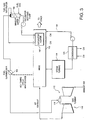
The basic concept of the invention can be understood with reference to the schematic representation of FIGURE 3. For convenience components that correspond to those identified above with reference to FIGURE 1 are identified with similar reference numerals but are only discussed in particular as necessary or desirable to an understanding of the fuel saturation and heating components and process.
Fuel gas is sent to asaturator 160, where moisture is absorbed by direct contact with hot water in a packed or trayed column. The saturator bottoms water is heated with gas turbine exhaust gas in thesaturator heater 162. Thesaturator heater 162 is placed in an optimal location relative to other HRSG tube banks which heat the cycle working fluid. Makeup water is provided to thefuel gas saturator 160, to replace the moisture absorbed by the gas. The saturated fuel gas leaving thesaturator 160 is further heated in afuel superheater 164 using, in the illustrated embodiment, a bottoming cycle heat source. The appropriate selection of bottoming cycle heat source(s) for the saturator heater and the fuel superheater results in a performance enhancement for the power cycle. - The addition of moisture to the fuel gas at the
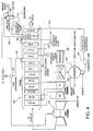
fuel gas saturator 160 increases the mass flow of the fuel gas. This increased mass flow increases power output of both the gas and steam turbines. Moreover, the use of low grade energy, which would not be useful for steam production, to introduce moisture and thus increase mass flow to the fuel, results in the gain in thermodynamic efficiency. This is also reflected as a reduction of the temperature mismatch in the HRSG below the LP-EV gas exit temperature and a corresponding decrease in thermodynamic exergy losses in the HRSG section. - By way of example, a first preferred implementation of the foregoing concept for a three pressure reheat Combined Cycle Power Plant is shown in FIGURE 4. Again, for convenience, components that correspond to those identified above with reference to FIGURES 1 and/or 2 are identified with similar reference numerals but are only discussed in particular as necessary or desirable to an understanding of the fuel saturation and heating components and process.
- In the embodiment of FIGURE 4, a section of the low pressure economizer (LP-EC) has been modified by placing a fuel saturator water heating coil section (SAT.HTR) 262 in parallel with an economizer section (LP-EC-1). This modification results in the reduction of the temperature mismatch and exergy loss in the
HRSG 232 below the LP-EV gas exit temperature, and a corresponding efficiency enhancement with fuel saturation. While in the illustrated embodiment of saturator heater is shown in parallel to the LP-EC-1, it could, for example, be arranged in an intertwined arrangement with the LP-EC-1, or placed at other locations in the HRSG. - The heated saturator water is sent to
saturator 260 viaconduit 266, where moisture is absorbed by the fuel gas by direct contact with the hot saturator water. The saturator bottoms water is returned to thesaturator water heater 262, e.g., with the aid of a saturator bottoms pump 268. Makeup water is provided, for example, from thefeed water pump 242 output as shown at F, to thefuel gas saturator 260, to replace the moisture absorbed by the gas. Although makeup water for fuel saturation is shown as taken from the feedwater transfer pump 242 discharge and/or from thefuel superheater 264, the saturator water (saturator makeup) could be taken from any other location in the cycle, or from an outside source. Thus, the illustrated source(s) are not to be limiting in this regard. - The saturated fuel gas leaving the
saturator 260 is further heated infuel superheater 264, preferably using a bottoming cycle heat source. The heating source for the fuel superheating in this example is IP-EC discharge water, viaconduit 258, but other heat sources could be used. In the embodiment of FIGURE 4, the IP-EC discharge water is returned to the IP-EC as shown at G and/or is used as makeup water for fuel saturation, as mentioned above. - As an illustration, with the gas turbine and ambient conditions identical to those used for the example depicted in FIGURES 1 and 2, the proposed system design shown in FIGURE 4 results in a +1.0% gain in combined cycle net efficiency, and a +0.9% gain in combined cycle net output. In this example, the gas leaves the LP-EV at 156°C (313°F) and the saturator bottoms water is heated to 148°C (298°F) in the saturator heater (SAT.HTR) which is placed, as noted above, in parallel with LP-EC-1. The boiler feed water is heated to 142°C (288°F) in LP-EC-1&2 as in the previous example.
- Fuel gas (100% Methane, CH4) enters the fuel gas saturator at a pressure of 400 psia and a temperature of 26.7°C (80°F). The fuel gas leaves the saturator at 140°C (284°F) saturated with water vapor. The saturated fuel gas leaving the gas saturator has a composition of approximately 86%v CH4 and 14%v H20. The saturated fuel gas is subsequently superheated to 185°C (365°F) in the fuel
superheating heat exchanger 264.
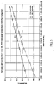
FIGURE 5 shows the plot of heat duty in millions of BTUs per hour versus the corresponding temperature of the hot composite (gas) and the cold composite (boiler feed water heating, and saturator bottoms water heating) for the HRSG section LP-EC-1&2 and the saturator heater, for the system shown in FIGURE 4. (For conversion purposes, 1,000,000 BTUs per hour = 293 kilowatts and 100°F = (100 - 32) / 9 x 5°C)..In this example, a temperature differential of 8.3°C (15°F) exists at the gas inlet to the HRSG sections after the LP-EV, with the temperature differential increasing to approximately 19.4°C (35°F) at a gas temperature of 121°C (250°F) and further increasing to 80 DEG F at the HRSG exit. The proposed cycle design of FIGURE 4 has thus resulted in a substantial reduction of the temperature mismatch (and exergy losses) in this example for gas temperatures between 156°C (313°F) and approximately 116°C (240°F), and a smaller reduction in the temperature mismatch at lower gas temperatures.
As noted above, the heat source for fuel superheating after saturation could be an extraction from other points in the HRSG or the Steam Turbine. Further, while in the example of FIGURE 4, water leaving the fuel superheater is returned to the IP-EC, that water could be admitted to any other appropriate location in the bottoming cycle, or to the fuel saturator as makeup water.
FIGURE 6 is a further illustrative embodiment of the invention, in which the saturated fuel gas leaving thesaturator 360 is superheated using the saturator bottoms liquid rather than cycle working fluid as in the embodiment of FIGURE 4.
As illustrated, the saturator bottoms liquid is initially heated in theheat exchanger 362 with heat from the HRSG exhaust gases. Anextraction 368 from the outlet ofheat exchanger 362 is sent toheat exchanger 370 for further heating. As illustrated,heat exchanger 370 is placed upstream ofheat exchanger 362 in theHRSG 332. Bothsaturator heaters outlet 372 fromheater 370 is used as the heat source for superheating the saturated fuel gas inheat exchanger 364. Theoutlet liquid stream 374 fromheater 364 is admitted to thefuel gas saturator 360 after being rejoined with theother flow 376 from the outlet ofheat exchanger 362, for direct contact heat and mass transfer with the fuel gas. - The apparatus and method of superheating the saturated fuel gas shown in FIGURE 6 provides a performance benefit due to additional moisture absorption by the gas, and increased safety in the system. The increased safety of this system is due to the elimination of the potential of fuel gas mixing with the cycle working fluid, which is a potential safety hazard when using cycle working fluid as the heat source for heat exchange with the fuel gas.
- The saturator bottoms pump 376 of FIGURE 6, and the like pumps illustrated in FIGURES 3 and 4, may be located at other positions in the system and additional pumps may be added to the system depicted.
Heater 370 may be eliminated from the system for some cycle designs with the extraction from the outlet ofheater 362 sent directly toheater 364. Furthermore, although not illustrated in particular, the saturation water (saturator make-up, or saturator bottoms) in any of the illustrated embodiments could be heated with low grade heat sources available in the cycle, such as lube oil heat, which are normally rejected to cooling water. This would result in a further performance enhancement to the proposed cycle. - As described above with reference to e.g., FIGURE 3, the fuel gas saturator assembly for adding water to and heating the fuel gas may be a saturator packed column. As an alternative, the saturator packed column shown in FIGURE 3 could be replaced by the combination of a water input and a fuel/water heat exchanger, as shown in FIGURE 7, while obtaining similar thermodynamic benefits of moisturizing the fuel. The choice of device (packed column or heat exchanger) would be determined by the heat and mass transfer effectiveness of the device, and the overall power plant economics. In FIGURE 7, the makeup water is sprayed into the fuel gas at the inlet to the heat exchanger (water atomization for spraying would be either using a pressure atomized nozzle, air atomized nozzle, or steam atomized. If steam or air atomized configurations are used it would be extracted from the cycle.). The two phase fuel/water mixture is heated in
heat exchanger 460 using heat extracted from an optimum HRSG location as shown in FIGURE 7, with a closed loop system. The saturated fuel gas leavingheat exchanger 460 is further superheated inheat exchanger 464 prior to entering the gas turbine combustor. The system otherwise generally corresponds to the other embodiments described hereinabove. - As will be appreciated, the invention can be applied to a single pressure or multi-pressure combined cycle power generation system with or without reheat.
Claims (7)
- A combined cycle system including a gas turbine (116), a steam turbine, (118, 218, 318) and a heat recovery steam generator (132, 232, 332), wherein gas turbine exhaust gas is used in the heat recovery steam generator (132, 232, 332) for generating steam for the steam turbine (118, 218, 318), said gas turbine exhaust gas flowing from an entry end to an exit end of the heat recovery steam generator (132, 232, 332), and wherein the system further comprises:a fuel gas saturator (160, 260, 360) having an inlet for hot saturator water, an inlet for fuel gas, an outlet for saturated fuel gas, and a saturator water outlet;a saturator water heater (162, 262; 362)a flow path for flowing saturator water from said saturator water outlet to said saturator heater (162, 262, 362), said saturator heater (162, 262, 362) being operatively coupled to a heat source in the heat recovery steam generator (132, 232, 332) for heating saturator water conducted thereto, using said heat source, to produce hot saturator water;a flow path for flowing hot saturator water produced by the saturator heater (162, 262, 362) to the hot saturator water inlet of the fuel gas saturator (160, 260, 360);a fuel superheater (164, 264, 364) for heating said saturated fuel gas;a flow path for flowing saturated fuel gas from said saturated fuel gas outlet to said fuel superheater (164, 264, 364) for heating said saturated fuel gas, to produce superheated, saturated fuel gas; anda flow path for flowing said superheated, saturated fuel gas to said gas turbine (116); Characterised in thatthe saturator heater (162, 262; 362) is located in the heat recovery steam generator (132, 232, 332).
- A combined cycle system according to claim 1, wherein said fuel superheater (164, 264, 364) is operatively coupled to a heat source in the heat recovery steam generator (132, 232, 332)., for heating said saturated fuel gas using said heat source.
- A combined cycle system according to claim 1 or 2, wherein said saturator heater (162, 262; 362) is operatively coupled to a first portion of the heat recovery steam generator (132, 232, 332), said fuel superheater (164, 264, 364) is operatively coupled to a second portion of the heat recovery steam generator (132, 232, 332),, and wherein said second portion is upstream of said first portion with respect to a flow direction of said gas turbine exhaust through the heat recovery steam generator (132, 232, 332)..
- A combined cycle system according to claim 1, 2 or 3, wherein said heat recovery steam generator (132, 232, 332) includes a low pressure evaporator and wherein said heat source is downstream of said low pressure evaporator with respect to a flow direction of said gas turbine exhaust through the heat recovery steam generator (132, 232, 332),.
- The combined cycle system as claimed in claim 1, the system further comprising:a condenser (126, 226, 326) for receiving exhaust steam from the steam turbine (118, 218, 318) and condensing said exhaust steam to water;said heat recovery steam generator (132, 232, 332) for receiving water from said condenser (126, 226, 326) and converting said water to steam for return to said steam turbine (118, 218, 318); anda fuel gas saturator assembly (160, 260, 360) for saturating fuel gas with water and heating said fuel gas;said heat recovery steam generator (132, 232, 332) including a first water heater (162, 262; 362) for heating water with heat from said exhaust gases, to define a heat source for said fuel gas saturator assembly (162, 262, 362); anda fuel gas superheater (164, 264, 364) for superheating fuel gas that has been saturated and heated by said fuel gas saturator assembly (162, 262, 362) for supply to said gas turbine (116).
- The combined cycle system according to claim 5, wherein said fuel gas saturator assembly water inlet is for adding water to a fuel gas supply for said gas turbine (116) and said system comprises a heat exchanger for heating fuel gas saturated with water input at said water inlet; said heat exchanger receiving heated water from said first water heater (162, 2762, 362).
- The combined cycle system according to claim 5 or 6, wherein said fuel gas saturator assembly (160, 260, 360) comprises a fuel gas saturator packed column having an inlet for hot water from said first water heater (162, 262, 362), an inlet for fuel gas, an outlet for saturated fuel gas, and a water outlet.
Applications Claiming Priority (2)
| Application Number | Priority Date | Filing Date | Title |
|---|---|---|---|
| US340510 | 1989-04-18 | ||
| US34051099A | 1999-07-01 | 1999-07-01 |
Publications (3)
| Publication Number | Publication Date |
|---|---|
| EP1065347A2 EP1065347A2 (en) | 2001-01-03 |
| EP1065347A3 EP1065347A3 (en) | 2003-03-05 |
| EP1065347B1 true EP1065347B1 (en) | 2007-03-07 |
Family
ID=23333685
Family Applications (1)
| Application Number | Title | Priority Date | Filing Date |
|---|---|---|---|
| EP00304151A Expired - Lifetime EP1065347B1 (en) | 1999-07-01 | 2000-05-17 | Method for fuel gas moisturization and heating |
Country Status (5)
| Country | Link |
|---|---|
| US (1) | US6389794B2 (en) |
| EP (1) | EP1065347B1 (en) |
| JP (1) | JP4700786B2 (en) |
| KR (1) | KR100766345B1 (en) |
| DE (1) | DE60033738T2 (en) |
Cited By (1)
| Publication number | Priority date | Publication date | Assignee | Title |
|---|---|---|---|---|
| CN101290120B (en) * | 2007-08-03 | 2010-06-09 | 周汉强 | Gas safe prewarming circulating system |
Families Citing this family (42)
| Publication number | Priority date | Publication date | Assignee | Title |
|---|---|---|---|---|
| US6474069B1 (en) | 2000-10-18 | 2002-11-05 | General Electric Company | Gas turbine having combined cycle power augmentation |
| US6694744B1 (en) | 2000-11-09 | 2004-02-24 | General Electric Company | Fuel gas moisturization system level control |
| US6499302B1 (en) * | 2001-06-29 | 2002-12-31 | General Electric Company | Method and apparatus for fuel gas heating in combined cycle power plants |
| WO2003091163A2 (en) * | 2002-04-24 | 2003-11-06 | Liprie Randal C | Cogeneration wasteheat evaporation system and method for wastewater treatment utilizing wasteheat recovery |
| EP1541811A3 (en) * | 2003-09-18 | 2005-06-22 | Matsushita Electric Industrial Co., Ltd. | Cogeneration system |
| US7284709B2 (en) * | 2003-11-07 | 2007-10-23 | Climate Energy, Llc | System and method for hydronic space heating with electrical power generation |
| US7040861B2 (en) * | 2004-03-04 | 2006-05-09 | General Electric Company | Method and apparatus for reducing self sealing flow in combined-cycle steam turbines |
| JP2006009713A (en) * | 2004-06-28 | 2006-01-12 | Hitachi Ltd | Cogeneration system and energy supply system |
| KR100579576B1 (en) * | 2004-08-17 | 2006-05-15 | 엘지전자 주식회사 | Steam supply and power generation system |
| KR100624815B1 (en) * | 2004-08-17 | 2006-09-20 | 엘지전자 주식회사 | Exhaust gas heat exchanger for cogeneration system |
| KR100600752B1 (en) * | 2004-08-17 | 2006-07-14 | 엘지전자 주식회사 | Steam supply and power generation system |
| US20070017207A1 (en) * | 2005-07-25 | 2007-01-25 | General Electric Company | Combined Cycle Power Plant |
| US7788930B2 (en) * | 2007-05-01 | 2010-09-07 | General Electric Company | Methods and systems for gas moisturization control |
| EP1990578A1 (en) | 2007-05-08 | 2008-11-12 | ALSTOM Technology Ltd | Gas turbine with water injection |
| US7874162B2 (en) * | 2007-10-04 | 2011-01-25 | General Electric Company | Supercritical steam combined cycle and method |
| US20090101822A1 (en) | 2007-10-18 | 2009-04-23 | General Electric Company | System and method for sensing fuel moisturization |
| US8015793B2 (en) * | 2008-07-18 | 2011-09-13 | Siemens Energy, Inc. | Fuel heating via exhaust gas extraction |
| US8205451B2 (en) * | 2008-08-05 | 2012-06-26 | General Electric Company | System and assemblies for pre-heating fuel in a combined cycle power plant |
| US20100031933A1 (en) * | 2008-08-05 | 2010-02-11 | Prakash Narayan | System and assemblies for hot water extraction to pre-heat fuel in a combined cycle power plant |
| US8186142B2 (en) * | 2008-08-05 | 2012-05-29 | General Electric Company | Systems and method for controlling stack temperature |
| US8438850B2 (en) * | 2009-02-17 | 2013-05-14 | General Electric Company | Waste heat utilization for pre-heating fuel |
| EP2290202A1 (en) * | 2009-07-13 | 2011-03-02 | Siemens Aktiengesellschaft | Cogeneration plant and cogeneration method |
| US8783043B2 (en) * | 2009-07-15 | 2014-07-22 | Siemens Aktiengesellschaft | Method for removal of entrained gas in a combined cycle power generation system |
| US20110016870A1 (en) * | 2009-07-23 | 2011-01-27 | Yefim Kashler | Method and apparatus for improved gas turbine efficiency and augmented power output |
| US8616005B1 (en) * | 2009-09-09 | 2013-12-31 | Dennis James Cousino, Sr. | Method and apparatus for boosting gas turbine engine performance |
| US20110113786A1 (en) * | 2009-11-18 | 2011-05-19 | General Electric Company | Combined cycle power plant with integrated organic rankine cycle device |
| US8783040B2 (en) * | 2010-02-25 | 2014-07-22 | General Electric Company | Methods and systems relating to fuel delivery in combustion turbine engines |
| EP2547888A4 (en) * | 2010-03-15 | 2016-03-16 | Ener Core Power Inc | Processing fuel and water |
| US20110232313A1 (en) * | 2010-03-24 | 2011-09-29 | General Electric Company | Chiller Condensate System |
| JP5479191B2 (en) * | 2010-04-07 | 2014-04-23 | 株式会社東芝 | Steam turbine plant |
| US8141367B2 (en) | 2010-05-19 | 2012-03-27 | General Electric Company | System and methods for pre-heating fuel in a power plant |
| US8881530B2 (en) | 2010-09-02 | 2014-11-11 | General Electric Company | Fuel heating system for startup of a combustion system |
| US8813471B2 (en) * | 2011-06-29 | 2014-08-26 | General Electric Company | System for fuel gas moisturization and heating |
| DE112012002934T5 (en) * | 2011-07-11 | 2014-04-24 | Hatch Ltd. | Advanced Combined Cycle Systems and Indirect Methanol Verbination Based Processes |
| US20130074508A1 (en) * | 2011-09-23 | 2013-03-28 | John Edward Sholes | Fuel Heating in Combined Cycle Turbomachinery |
| JP5591213B2 (en) * | 2011-11-25 | 2014-09-17 | 三菱電機株式会社 | Inverter device and air conditioner equipped with the same |
| US9422868B2 (en) | 2013-04-09 | 2016-08-23 | General Electric Company | Simple cycle gas turbomachine system having a fuel conditioning system |
| EP2824293A1 (en) * | 2013-07-08 | 2015-01-14 | Alstom Technology Ltd | Power plant with integrated fuel gas preheating |
| US9840939B2 (en) * | 2014-07-14 | 2017-12-12 | General Electric Company | Variable fuel gas moisture control for gas turbine combustor |
| EP3290794A1 (en) * | 2016-09-05 | 2018-03-07 | Technip France | Method for reducing nox emission |
| US10900418B2 (en) * | 2017-09-28 | 2021-01-26 | General Electric Company | Fuel preheating system for a combustion turbine engine |
| WO2024091836A1 (en) * | 2022-10-25 | 2024-05-02 | Ge Infrastructure Technology Llc | Combined cycle power plant having reduced parasitic pumping losses |
Family Cites Families (22)
| Publication number | Priority date | Publication date | Assignee | Title |
|---|---|---|---|---|
| NL191444C (en) * | 1982-02-16 | 1995-07-04 | Shell Int Research | Method for generating mechanical energy and generating steam using a gas turbine. |
| JPS59105909A (en) * | 1982-12-09 | 1984-06-19 | Mitsubishi Heavy Ind Ltd | Compound electric power generating system by fuel cracking |
| JPH076409B2 (en) * | 1986-10-21 | 1995-01-30 | 三菱重工業株式会社 | Temperature control method in catalytic reduction |
| US4753068A (en) | 1987-01-15 | 1988-06-28 | El Masri Maher A | Gas turbine cycle incorporating simultaneous, parallel, dual-mode heat recovery |
| SE468910B (en) * | 1989-04-18 | 1993-04-05 | Gen Electric | POWER SUPPLY UNIT, BY WHICH THE CONTENT OF DAMAGE POLLUTANTS IN THE EXHAUSTS IS REDUCED |
| US5170622A (en) | 1991-04-02 | 1992-12-15 | Cheng Dah Y | Advanced regenerative parallel compound dual fluid heat engine Advanced Cheng Cycle (ACC) |
| US5233826A (en) | 1991-04-02 | 1993-08-10 | Cheng Dah Y | Method for starting and operating an advanced regenerative parallel compound dual fluid heat engine-advanced cheng cycle (ACC) |
| GB9208646D0 (en) | 1992-04-22 | 1992-06-10 | Boc Group Plc | Air separation |
| NL9201256A (en) * | 1992-07-13 | 1994-02-01 | Kema Nv | STEG DEVICE FOR GENERATING ELECTRICITY WITH WET NATURAL GAS. |
| DE4321081A1 (en) * | 1993-06-24 | 1995-01-05 | Siemens Ag | Process for operating a gas and steam turbine plant and a combined cycle gas plant |
| US5450821A (en) | 1993-09-27 | 1995-09-19 | Exergy, Inc. | Multi-stage combustion system for externally fired power plants |
| US5577377A (en) | 1993-11-04 | 1996-11-26 | General Electric Co. | Combined cycle with steam cooled gas turbine |
| US5628179A (en) | 1993-11-04 | 1997-05-13 | General Electric Co. | Steam attemperation circuit for a combined cycle steam cooled gas turbine |
| US5544479A (en) | 1994-02-10 | 1996-08-13 | Longmark Power International, Inc. | Dual brayton-cycle gas turbine power plant utilizing a circulating pressurized fluidized bed combustor |
| JP3787820B2 (en) * | 1996-02-16 | 2006-06-21 | 石川島播磨重工業株式会社 | Gasification combined power generation facility |
| US5867977A (en) | 1996-05-14 | 1999-02-09 | The Dow Chemical Company | Method and apparatus for achieving power augmentation in gas turbines via wet compression |
| JPH10131716A (en) | 1996-10-28 | 1998-05-19 | Mitsubishi Heavy Ind Ltd | Method and device for controlling steam cooling system of gas turbine |
| JP3564242B2 (en) | 1996-10-29 | 2004-09-08 | 三菱重工業株式会社 | Cooling steam system for steam-cooled gas turbine |
| JP3564241B2 (en) | 1996-10-29 | 2004-09-08 | 三菱重工業株式会社 | Combined cycle power plant |
| JPH10131719A (en) | 1996-10-29 | 1998-05-19 | Mitsubishi Heavy Ind Ltd | Steam cooling gas turbine system |
| JPH1193694A (en) * | 1997-09-18 | 1999-04-06 | Toshiba Corp | Gas turbine plant |
| JPH11156117A (en) * | 1997-11-26 | 1999-06-15 | Ishikawajima Harima Heavy Ind Co Ltd | Saturation facility |
-
2000
- 2000-05-17 DE DE60033738T patent/DE60033738T2/en not_active Expired - Lifetime
- 2000-05-17 EP EP00304151A patent/EP1065347B1/en not_active Expired - Lifetime
- 2000-06-01 JP JP2000163932A patent/JP4700786B2/en not_active Expired - Lifetime
- 2000-06-23 KR KR1020000034667A patent/KR100766345B1/en active IP Right Grant
-
2001
- 2001-04-10 US US09/829,437 patent/US6389794B2/en not_active Expired - Lifetime
Cited By (1)
| Publication number | Priority date | Publication date | Assignee | Title |
|---|---|---|---|---|
| CN101290120B (en) * | 2007-08-03 | 2010-06-09 | 周汉强 | Gas safe prewarming circulating system |
Also Published As
| Publication number | Publication date |
|---|---|
| DE60033738T2 (en) | 2007-11-08 |
| JP4700786B2 (en) | 2011-06-15 |
| EP1065347A2 (en) | 2001-01-03 |
| JP2001020757A (en) | 2001-01-23 |
| US6389794B2 (en) | 2002-05-21 |
| DE60033738D1 (en) | 2007-04-19 |
| US20010049934A1 (en) | 2001-12-13 |
| KR100766345B1 (en) | 2007-10-15 |
| KR20010015055A (en) | 2001-02-26 |
| EP1065347A3 (en) | 2003-03-05 |
Similar Documents
| Publication | Publication Date | Title |
|---|---|---|
| EP1065347B1 (en) | Method for fuel gas moisturization and heating | |
| CN101403322B (en) | Supercritical steam combined cycle and method | |
| US5428950A (en) | Steam cycle for combined cycle with steam cooled gas turbine | |
| US5412937A (en) | Steam cycle for combined cycle with steam cooled gas turbine | |
| EP0676532B1 (en) | Steam injected gas turbine system with topping steam turbine | |
| CA2718367C (en) | Direct heating organic ranking cycle | |
| US6065280A (en) | Method of heating gas turbine fuel in a combined cycle power plant using multi-component flow mixtures | |
| US5623822A (en) | Method of operating a waste-to-energy plant having a waste boiler and gas turbine cycle | |
| CN203670119U (en) | Gas-steam combined cycle power device | |
| US20070017207A1 (en) | Combined Cycle Power Plant | |
| Fraize et al. | Effects of steam injection on the performance of gas turbine power cycles | |
| US6244033B1 (en) | Process for generating electric power | |
| KR960038080A (en) | Combined cycle system, reheat steam cycle and superheated steam temperature control | |
| US9188028B2 (en) | Gas turbine system with reheat spray control | |
| JP2000257407A (en) | Improved bottoming cycle for cooling air around inlet of gas-turbine combined cycle plant | |
| US5361377A (en) | Apparatus and method for producing electrical power | |
| Srinivas et al. | Sensitivity analysis of STIG based combined cycle with dual pressure HRSG | |
| US20040139747A1 (en) | Steam ammonia power cycle | |
| Srinivas et al. | Parametric simulation of steam injected gas turbine combined cycle | |
| IL124422A (en) | Method and device for generating steam | |
| CN115003958A (en) | Device with an add-on module | |
| CA2983533C (en) | Combined cycle power generation | |
| Kudinov et al. | Development of technologies to increase efficiency and reliability of combined cycle power plant with double-pressure heat recovery steam generator | |
| JP2003521629A (en) | Integrated gasification combined cycle power plant with kalina bottoming cycle | |
| WO2024038724A1 (en) | Combined cycle power generator |
Legal Events
| Date | Code | Title | Description |
|---|---|---|---|
| PUAI | Public reference made under article 153(3) epc to a published international application that has entered the european phase |
Free format text: ORIGINAL CODE: 0009012 |
|
| AK | Designated contracting states |
Kind code of ref document: A2 Designated state(s): AT BE CH CY DE DK ES FI FR GB GR IE IT LI LU MC NL PT SE |
|
| AX | Request for extension of the european patent |
Free format text: AL;LT;LV;MK;RO;SI |
|
| PUAL | Search report despatched |
Free format text: ORIGINAL CODE: 0009013 |
|
| AK | Designated contracting states |
Designated state(s): AT BE CH CY DE DK ES FI FR GB GR IE IT LI LU MC NL PT SE Kind code of ref document: A3 Designated state(s): AT BE CH CY DE DK ES FI FR GB GR IE IT LI LU MC NL PT SE |
|
| AX | Request for extension of the european patent |
Extension state: AL LT LV MK RO SI |
|
| 17P | Request for examination filed |
Effective date: 20030905 |
|
| AKX | Designation fees paid |
Designated state(s): CH DE FR GB IT LI |
|
| 17Q | First examination report despatched |
Effective date: 20050630 |
|
| RTI1 | Title (correction) |
Free format text: METHOD FOR FUEL GAS MOISTURIZATION AND HEATING |
|
| GRAP | Despatch of communication of intention to grant a patent |
Free format text: ORIGINAL CODE: EPIDOSNIGR1 |
|
| GRAS | Grant fee paid |
Free format text: ORIGINAL CODE: EPIDOSNIGR3 |
|
| GRAA | (expected) grant |
Free format text: ORIGINAL CODE: 0009210 |
|
| AK | Designated contracting states |
Kind code of ref document: B1 Designated state(s): CH DE FR GB IT LI |
|
| REG | Reference to a national code |
Ref country code: GB Ref legal event code: FG4D |
|
| REG | Reference to a national code |
Ref country code: CH Ref legal event code: EP |
|
| REG | Reference to a national code |
Ref country code: CH Ref legal event code: NV Representative=s name: SERVOPATENT GMBH |
|
| REF | Corresponds to: |
Ref document number: 60033738 Country of ref document: DE Date of ref document: 20070419 Kind code of ref document: P |
|
| ET | Fr: translation filed | ||
| PLBE | No opposition filed within time limit |
Free format text: ORIGINAL CODE: 0009261 |
|
| STAA | Information on the status of an ep patent application or granted ep patent |
Free format text: STATUS: NO OPPOSITION FILED WITHIN TIME LIMIT |
|
| 26N | No opposition filed |
Effective date: 20071210 |
|
| REG | Reference to a national code |
Ref country code: CH Ref legal event code: PFA Owner name: GENERAL ELECTRIC COMPANY Free format text: GENERAL ELECTRIC COMPANY#1 RIVER ROAD#SCHENECTADY, NY 12345 (US) -TRANSFER TO- GENERAL ELECTRIC COMPANY#1 RIVER ROAD#SCHENECTADY, NY 12345 (US) |
|
| REG | Reference to a national code |
Ref country code: FR Ref legal event code: PLFP Year of fee payment: 17 |
|
| REG | Reference to a national code |
Ref country code: FR Ref legal event code: PLFP Year of fee payment: 18 |
|
| PGFP | Annual fee paid to national office [announced via postgrant information from national office to epo] |
Ref country code: CH Payment date: 20170527 Year of fee payment: 18 Ref country code: GB Payment date: 20170530 Year of fee payment: 18 Ref country code: FR Payment date: 20170525 Year of fee payment: 18 Ref country code: DE Payment date: 20170530 Year of fee payment: 18 |
|
| REG | Reference to a national code |
Ref country code: DE Ref legal event code: R119 Ref document number: 60033738 Country of ref document: DE |
|
| REG | Reference to a national code |
Ref country code: CH Ref legal event code: PL |
|
| GBPC | Gb: european patent ceased through non-payment of renewal fee |
Effective date: 20180517 |
|
| PG25 | Lapsed in a contracting state [announced via postgrant information from national office to epo] |
Ref country code: LI Free format text: LAPSE BECAUSE OF NON-PAYMENT OF DUE FEES Effective date: 20180531 Ref country code: CH Free format text: LAPSE BECAUSE OF NON-PAYMENT OF DUE FEES Effective date: 20180531 |
|
| PG25 | Lapsed in a contracting state [announced via postgrant information from national office to epo] |
Ref country code: FR Free format text: LAPSE BECAUSE OF NON-PAYMENT OF DUE FEES Effective date: 20180531 Ref country code: GB Free format text: LAPSE BECAUSE OF NON-PAYMENT OF DUE FEES Effective date: 20180517 Ref country code: DE Free format text: LAPSE BECAUSE OF NON-PAYMENT OF DUE FEES Effective date: 20181201 |
|
| PGFP | Annual fee paid to national office [announced via postgrant information from national office to epo] |
Ref country code: IT Payment date: 20190418 Year of fee payment: 20 |