EP1065116A2 - Isolation valve armature configured to reduce Bernoulli force during normal braking operation - Google Patents
Isolation valve armature configured to reduce Bernoulli force during normal braking operation Download PDFInfo
- Publication number
- EP1065116A2 EP1065116A2 EP00113921A EP00113921A EP1065116A2 EP 1065116 A2 EP1065116 A2 EP 1065116A2 EP 00113921 A EP00113921 A EP 00113921A EP 00113921 A EP00113921 A EP 00113921A EP 1065116 A2 EP1065116 A2 EP 1065116A2
- Authority
- EP
- European Patent Office
- Prior art keywords
- valve
- armature
- isolation valve
- isolation
- bernoulli force
- Prior art date
- Legal status (The legal status is an assumption and is not a legal conclusion. Google has not performed a legal analysis and makes no representation as to the accuracy of the status listed.)
- Granted
Links
Images


Classifications
-
- B—PERFORMING OPERATIONS; TRANSPORTING
- B60—VEHICLES IN GENERAL
- B60T—VEHICLE BRAKE CONTROL SYSTEMS OR PARTS THEREOF; BRAKE CONTROL SYSTEMS OR PARTS THEREOF, IN GENERAL; ARRANGEMENT OF BRAKING ELEMENTS ON VEHICLES IN GENERAL; PORTABLE DEVICES FOR PREVENTING UNWANTED MOVEMENT OF VEHICLES; VEHICLE MODIFICATIONS TO FACILITATE COOLING OF BRAKES
- B60T8/00—Arrangements for adjusting wheel-braking force to meet varying vehicular or ground-surface conditions, e.g. limiting or varying distribution of braking force
- B60T8/32—Arrangements for adjusting wheel-braking force to meet varying vehicular or ground-surface conditions, e.g. limiting or varying distribution of braking force responsive to a speed condition, e.g. acceleration or deceleration
- B60T8/34—Arrangements for adjusting wheel-braking force to meet varying vehicular or ground-surface conditions, e.g. limiting or varying distribution of braking force responsive to a speed condition, e.g. acceleration or deceleration having a fluid pressure regulator responsive to a speed condition
- B60T8/36—Arrangements for adjusting wheel-braking force to meet varying vehicular or ground-surface conditions, e.g. limiting or varying distribution of braking force responsive to a speed condition, e.g. acceleration or deceleration having a fluid pressure regulator responsive to a speed condition including a pilot valve responding to an electromagnetic force
- B60T8/3615—Electromagnetic valves specially adapted for anti-lock brake and traction control systems
- B60T8/363—Electromagnetic valves specially adapted for anti-lock brake and traction control systems in hydraulic systems
-
- B—PERFORMING OPERATIONS; TRANSPORTING
- B60—VEHICLES IN GENERAL
- B60T—VEHICLE BRAKE CONTROL SYSTEMS OR PARTS THEREOF; BRAKE CONTROL SYSTEMS OR PARTS THEREOF, IN GENERAL; ARRANGEMENT OF BRAKING ELEMENTS ON VEHICLES IN GENERAL; PORTABLE DEVICES FOR PREVENTING UNWANTED MOVEMENT OF VEHICLES; VEHICLE MODIFICATIONS TO FACILITATE COOLING OF BRAKES
- B60T8/00—Arrangements for adjusting wheel-braking force to meet varying vehicular or ground-surface conditions, e.g. limiting or varying distribution of braking force
- B60T8/32—Arrangements for adjusting wheel-braking force to meet varying vehicular or ground-surface conditions, e.g. limiting or varying distribution of braking force responsive to a speed condition, e.g. acceleration or deceleration
- B60T8/34—Arrangements for adjusting wheel-braking force to meet varying vehicular or ground-surface conditions, e.g. limiting or varying distribution of braking force responsive to a speed condition, e.g. acceleration or deceleration having a fluid pressure regulator responsive to a speed condition
- B60T8/50—Arrangements for adjusting wheel-braking force to meet varying vehicular or ground-surface conditions, e.g. limiting or varying distribution of braking force responsive to a speed condition, e.g. acceleration or deceleration having a fluid pressure regulator responsive to a speed condition having means for controlling the rate at which pressure is reapplied to or released from the brake
- B60T8/5018—Pressure reapplication using restrictions
- B60T8/5025—Pressure reapplication using restrictions in hydraulic brake systems
Landscapes
- Physics & Mathematics (AREA)
- Engineering & Computer Science (AREA)
- Fluid Mechanics (AREA)
- Transportation (AREA)
- Mechanical Engineering (AREA)
- Electromagnetism (AREA)
- Magnetically Actuated Valves (AREA)
- Regulating Braking Force (AREA)
- Valves And Accessory Devices For Braking Systems (AREA)
- Lift Valve (AREA)
Abstract
Description
| Bernoulli force when fully open (base supply) | Bernoulli force when partially open (ABS) | |
| Isolation valve without edge groove | 3.70 N (closing) | 4.66 N (closing) |
| Isolation valve with edge groove | 0.30 N (opening) | 4.32 N (closing) |
Claims (20)
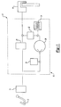
- An isolation valve for controlling fluid flow in a vehicular braking system, said valve comprising:a solenoid coil assembly;an armature moveably positioned within said solenoid coil assembly, said armature having a ball end engaging a ball seat, said armature configured to modify Bernoulli force that affects movement of said armature when said solenoid coil assembly is de-energized.
- The isolation valve of claim 1, where said armature configuration eliminates Bernoulli force during normal braking events when said isolation valve is fully open.
- The isolation valve of claim 2, where Bernoulli force generated when said isolation valve is partially open during a controlled braking event is not eliminated by said edge groove.
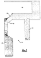
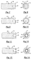
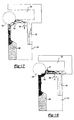
- An isolation valve for use in a hydraulic control unit for a vehicular brake system, said isolation valve comprising:a valve body housing defining a valve cavity;a valve stem mounted in said valve cavity, said valve stem having a coaxial fluid passage therethrough;a cylindrical sleeve mounted on said valve body surrounding said valve stem;an armature slidably mounted in said cylindrical sleeve and biased by a spring in a normally open position; said armature havinga valve end for controlling fluid flow through said coaxial fluid passage, andan edge groove at said valve end to modify Bernoulli force that affects movement of said armature.
- The isolation valve of claim 4, where said edge groove eliminates Bernoulli force during normal braking events when said isolation valve is fully open.
- The isolation valve of claim 5, where Bernoulli force generated when said isolation valve is partially open during a controlled braking event is not eliminated by said edge groove.
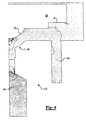
- An isolation valve for use in a hydraulic control unit for a vehicular brake system, said isolation valve comprising:a valve body housing defining a valve cavity;a valve stem mounted in said valve cavity, said valve stem having a coaxial fluid passage therethrough;a cylindrical sleeve mounted on said valve body surrounding said valve stem;an armature slideably mounted in said cylindrical sleeve and biased by a spring in a normally open position; said armature havinga valve end for controlling fluid flow through said coaxial fluid passage, andan outer step at said valve end to modify Bernoulli force that affects movement of said armature.
- The isolation valve of claim 4, where said outer step eliminates Bernoulli force during normal braking events when said isolation valve is fully open.
- The isolation valve of claim 5, where Bernoulli force generated when said isolation valve is partially open during a controlled braking event is not eliminated by said outer step.
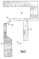
- An isolation valve for use in a hydraulic control unit for a vehicular brake system, said isolation valve comprising:a valve body housing defining a valve cavity;a valve stem mounted in said valve cavity, said valve stem having a coaxial fluid passage therethrough;a cylindrical sleeve mounted on said valve body surrounding said valve stem;an armature slideably mounted in said cylindrical sleeve and biased by a spring in a normally open position; said armature havinga valve end for controlling fluid flow through said coaxial fluid passage, andan annular cavity at said valve end to modify Bernoulli force that affects movement of said armature.
- The isolation valve of claim 4, where said annular cavity eliminates Bernoulli force during normal braking events when said isolation valve is fully open.
- The isolation valve of claim 5, where Bernoulli force generated when said isolation valve is partially open during a controlled braking event is not eliminated by said annular cavity.
- An isolation valve for use in a hydraulic control unit for a vehicular brake system, said isolation valve comprising:a valve body housing defining a valve cavity;a valve stem mounted in said valve cavity, said valve stem having a coaxial fluid passage therethrough;a cylindrical sleeve mounted on said valve body surrounding said valve stem;an armature slideably mounted in said cylindrical sleeve and biased by a spring in a normally open position; said armature havinga valve end for controlling fluid flow through said coaxial fluid passage, andan outer step and an annular cavity at said valve end to modify Bernoulli force that affects movement of said armature.
- The isolation valve of claim 4, where said outer step and said annular cavity eliminate Bernoulli force during normal braking events when said isolation valve is fully open.
- The isolation valve of claim 5, where Bernoulli force generated when said isolation valve is partially open during a controlled braking event is not eliminated by said outer step and said annular cavity.
- A method of manufacturing an isolation valve for use in a hydraulic control unit for a vehicular brake system comprising the steps of:forming a valve cavity in a valve body housing;mounting a valve stem in said valve cavity, said valve stem having a coaxial fluid passage therethrough;mounting a cylindrical sleeve in said valve body surrounding said valve stem;forming an armature having a valve end for controlling fluid flow through said coaxial fluid passage;configuring said valve end to modify Bernoulli force that affects movement of said armature;mounting the configured armature in said cylindrical sleeve so that it is slideable and biased by a spring in a normally open position.
- The method of manufacturing an isolation valve of claim 16, where said valve end is configured with an edge groove to modify Bernoulli force that affects movement of said armature.
- The method of manufacturing an isolation valve of claim 16, where said valve end is configured with an outer step to modify Bernoulli force that affects movement of said armature.
- The method of manufacturing an isolation valve of claim 16, where said valve end is configured with an annular cavity to modify Bernoulli force that affects movement of said armature.
- The method of manufacturing an isolation valve of claim 16, where said valve end is configured with an outer step and an annular cavity to modify Bernoulli force that affects movement of said armature.
Applications Claiming Priority (2)
| Application Number | Priority Date | Filing Date | Title |
|---|---|---|---|
| US340942 | 1989-04-20 | ||
| US09/340,492 US6471305B1 (en) | 1999-06-30 | 1999-06-30 | Isolation valve armature configured to reduce bernoulli force during normal braking operation |
Publications (3)
| Publication Number | Publication Date |
|---|---|
| EP1065116A2 true EP1065116A2 (en) | 2001-01-03 |
| EP1065116A3 EP1065116A3 (en) | 2003-04-16 |
| EP1065116B1 EP1065116B1 (en) | 2005-02-09 |
Family
ID=23333583
Family Applications (1)
| Application Number | Title | Priority Date | Filing Date |
|---|---|---|---|
| EP00113921A Expired - Lifetime EP1065116B1 (en) | 1999-06-30 | 2000-06-30 | Isolation valve armature configured to reduce Bernoulli force during normal braking operation |
Country Status (4)
| Country | Link |
|---|---|
| US (1) | US6471305B1 (en) |
| EP (1) | EP1065116B1 (en) |
| JP (1) | JP2001055132A (en) |
| DE (1) | DE60017981T2 (en) |
Cited By (5)
| Publication number | Priority date | Publication date | Assignee | Title |
|---|---|---|---|---|
| KR100423646B1 (en) * | 2000-07-18 | 2004-03-22 | 주식회사 만도 | Normal open type solenoid valve for ABS |
| WO2006026503A1 (en) * | 2004-08-27 | 2006-03-09 | Kelsey-Hayes Company | Solenoid valve with spherical armature |
| US7341320B2 (en) | 2003-05-19 | 2008-03-11 | Hitachi, Ltd. | Electromagnetically actuated valve |
| WO2008043623A1 (en) * | 2006-10-10 | 2008-04-17 | Robert Bosch Gmbh | Solenoid valve |
| WO2012107137A1 (en) * | 2011-02-08 | 2012-08-16 | Robert Bosch Gmbh | Magnet valve for controlling a fluid |
Families Citing this family (17)
| Publication number | Priority date | Publication date | Assignee | Title |
|---|---|---|---|---|
| JP2002323162A (en) * | 2001-04-26 | 2002-11-08 | Sumitomo Denko Brake Systems Kk | Solenoid valve |
| KR100466952B1 (en) * | 2002-04-24 | 2005-01-24 | 현대모비스 주식회사 | Anti-Lock Brake Equipment Solenoid Valve |
| KR100465811B1 (en) * | 2002-04-24 | 2005-01-13 | 현대모비스 주식회사 | Anti-Lock Brake Equipment Solenoid Valve |
| KR100465201B1 (en) * | 2002-07-16 | 2005-01-13 | 현대모비스 주식회사 | Solenoid Controlled Valve of Anti-lock Brake System |
| DE102004001565A1 (en) * | 2004-01-10 | 2005-08-04 | Robert Bosch Gmbh | Electromagnetic valve, in particular for a brake system of a motor vehicle |
| DE102004030428A1 (en) * | 2004-06-24 | 2006-01-19 | Robert Bosch Gmbh | valve device |
| US7367636B2 (en) * | 2005-02-16 | 2008-05-06 | Bendix Commercial Vehicle Systems, Llc | Solenoid armature with integrated spherical soft seal |
| DE102006047917A1 (en) * | 2006-10-10 | 2008-04-17 | Robert Bosch Gmbh | Valve body and associated solenoid valve |
| KR100839715B1 (en) * | 2007-05-02 | 2008-06-19 | 현대모비스 주식회사 | Side flux path inlet typed solenoid valve |
| US8192172B2 (en) | 2009-04-06 | 2012-06-05 | Woodward, Inc. | Flow sensing shutoff valve |
| DE102009019534A1 (en) * | 2009-04-30 | 2010-12-02 | Schaeffler Technologies Gmbh & Co. Kg | Electromagnetic hydraulic valve |
| KR101198752B1 (en) | 2010-09-16 | 2012-11-12 | 주식회사 만도 | Solenoid valve for brake system |
| KR101198751B1 (en) | 2010-09-20 | 2012-11-12 | 주식회사 만도 | Solenoid valve for anti-lock brake system |
| KR101617802B1 (en) * | 2014-10-30 | 2016-05-03 | 현대모비스 주식회사 | Decompression solenoid valve |
| US10544770B2 (en) | 2017-06-29 | 2020-01-28 | Woodward, Inc. | Mecha-hydraulic actuated inlet control valve |
| DE102018201883A1 (en) * | 2018-02-07 | 2019-08-08 | Continental Teves Ag & Co. Ohg | Electromagnetic valve, in particular for hydraulic motor vehicle brake systems |
| JP7103066B2 (en) * | 2018-08-28 | 2022-07-20 | 浜名湖電装株式会社 | Fluid control valve |
Family Cites Families (31)
| Publication number | Priority date | Publication date | Assignee | Title |
|---|---|---|---|---|
| DE2113001B1 (en) * | 1971-03-18 | 1972-02-03 | Westinghouse Bremsen Und Appba | Electromagnetically operated vent valve with high acceleration |
| DE2134067A1 (en) * | 1971-07-08 | 1973-01-25 | Servo Technik Gmbh | ELECTROMAGNETIC VALVE |
| GB1433445A (en) * | 1973-06-05 | 1976-04-28 | Rau Swf Autozubehoer | Magnetic valve |
| US4021152A (en) | 1974-12-06 | 1977-05-03 | Taisan Industrial Co., Ltd. | Electromagnetic pump |
| US4791958A (en) | 1983-12-21 | 1988-12-20 | Brundage Robert W | Solenoid controlled fluid valve |
| US4531708A (en) * | 1984-08-21 | 1985-07-30 | Honeywell Lucifer Sa | Solenoid valve |
| US4865399A (en) * | 1985-08-09 | 1989-09-12 | Kelsey Hayes Company | Vehicle anti-lock brake system |
| US4668023A (en) * | 1985-08-09 | 1987-05-26 | Kelsey-Hayes Company | Control valve for an anti-lock brake system |
| DE3534665A1 (en) * | 1985-09-28 | 1987-04-09 | Bosch Gmbh Robert | Two-position solenoid valve |
| KR930006510B1 (en) * | 1988-07-29 | 1993-07-16 | 미쓰비시전기 주식회사 | Solenoid valve |
| US5011113A (en) * | 1988-12-29 | 1991-04-30 | Applied Power Inc. | Fluid control valve |
| US4941447A (en) * | 1989-02-21 | 1990-07-17 | Colt Industries Inc. | Metering valve |
| US5253676A (en) * | 1992-08-13 | 1993-10-19 | Moog Controls, Inc. | Low Bernoulli force control orifice |
| JP2569208Y2 (en) * | 1992-10-13 | 1998-04-22 | 株式会社ユニシアジェックス | Solenoid valve structure |
| JP3294382B2 (en) * | 1992-10-30 | 2002-06-24 | 株式会社デンソー | Flow control valve |
| DE4324533C2 (en) | 1993-07-21 | 1996-04-25 | Lucas Ind Plc | Valve arrangement |
| DE4332372A1 (en) | 1993-09-23 | 1995-03-30 | Bosch Gmbh Robert | Electromagnetically actuated valve, in particular for slip-controlled hydraulic brake systems in motor vehicles |
| US5791747A (en) * | 1994-02-18 | 1998-08-11 | Kelsey-Hayes Company | Hydraulic valve control unit for vehicular anti-lock brake and traction control systems |
| US5364067A (en) | 1994-02-18 | 1994-11-15 | Kelsey-Hayes Corporation | Vehicular anti-lock brake system hydraulic control valve and method of making same |
| US5439279A (en) * | 1994-02-18 | 1995-08-08 | Kelsey-Hayes Company | Vehicular anti-lock brake system hydraulic control unit |
| DE19530899C2 (en) * | 1995-08-23 | 2003-08-21 | Bosch Gmbh Robert | Solenoid valve, in particular for a slip-controlled, hydraulic brake system for motor vehicles |
| US6026847A (en) | 1995-10-11 | 2000-02-22 | Reinicke; Robert H. | Magnetostrictively actuated valve |
| DE19604315A1 (en) | 1996-02-07 | 1997-08-14 | Bosch Gmbh Robert | Electromagnetically operated valve, in particular for hydraulic brake systems in motor vehicles |
| DE19604317A1 (en) * | 1996-02-07 | 1997-08-14 | Bosch Gmbh Robert | Electromagnetically operated valve, in particular for hydraulic brake systems in motor vehicles |
| US5887621A (en) * | 1996-04-10 | 1999-03-30 | Applied Power Inc. | On/off bidirectional valve |
| DE19649225A1 (en) | 1996-11-27 | 1998-05-28 | Nass Magnet Gmbh | Valve |
| WO1998040260A1 (en) * | 1997-03-11 | 1998-09-17 | Kelsey-Hayes Company | Sleeve and armature subassembly for control valves of vehicular braking systems and method of forming |
| US5791339A (en) | 1997-03-13 | 1998-08-11 | Nellcor Puritan Bennettt Incorprated | Spring piloted safety valve with jet venturi bias |
| US6065734A (en) | 1997-10-03 | 2000-05-23 | Kelsey-Hayes Company | Control valve for a hydraulic control unit of vehicular brake systems |
| US6029703A (en) | 1998-12-18 | 2000-02-29 | Borg-Warner Automotive, Inc. | Pressure solenoid control valve with flux shunt |
| US6065495A (en) | 1999-02-04 | 2000-05-23 | General Motors Corporation | Two-position, three-way solenoid-actuated valve |
-
1999
- 1999-06-30 US US09/340,492 patent/US6471305B1/en not_active Expired - Fee Related
-
2000
- 2000-06-29 JP JP2000195470A patent/JP2001055132A/en active Pending
- 2000-06-30 EP EP00113921A patent/EP1065116B1/en not_active Expired - Lifetime
- 2000-06-30 DE DE60017981T patent/DE60017981T2/en not_active Expired - Fee Related
Cited By (8)
| Publication number | Priority date | Publication date | Assignee | Title |
|---|---|---|---|---|
| KR100423646B1 (en) * | 2000-07-18 | 2004-03-22 | 주식회사 만도 | Normal open type solenoid valve for ABS |
| US7341320B2 (en) | 2003-05-19 | 2008-03-11 | Hitachi, Ltd. | Electromagnetically actuated valve |
| DE102004024673B4 (en) * | 2003-05-19 | 2012-01-12 | Hitachi, Ltd. | Electromagnetically actuated valve |
| WO2006026503A1 (en) * | 2004-08-27 | 2006-03-09 | Kelsey-Hayes Company | Solenoid valve with spherical armature |
| US7195226B2 (en) | 2004-08-27 | 2007-03-27 | Kelsey-Hayes Company | Solenoid valve with spherical armature |
| WO2008043623A1 (en) * | 2006-10-10 | 2008-04-17 | Robert Bosch Gmbh | Solenoid valve |
| WO2012107137A1 (en) * | 2011-02-08 | 2012-08-16 | Robert Bosch Gmbh | Magnet valve for controlling a fluid |
| US9133957B2 (en) | 2011-02-08 | 2015-09-15 | Robert Bosch Gmbh | Magnet valve for controlling a fluid |
Also Published As
| Publication number | Publication date |
|---|---|
| EP1065116B1 (en) | 2005-02-09 |
| US6471305B1 (en) | 2002-10-29 |
| EP1065116A3 (en) | 2003-04-16 |
| DE60017981D1 (en) | 2005-03-17 |
| DE60017981T2 (en) | 2006-04-06 |
| JP2001055132A (en) | 2001-02-27 |
Similar Documents
| Publication | Publication Date | Title |
|---|---|---|
| EP1065116B1 (en) | Isolation valve armature configured to reduce Bernoulli force during normal braking operation | |
| EP0997363B1 (en) | Supply valve for a hydraulic control unit of a vehicular braking system | |
| US5865213A (en) | Controllable valve | |
| KR100495961B1 (en) | Solenoid valve | |
| JP3365151B2 (en) | solenoid valve | |
| JP3786477B2 (en) | Solenoid valves for automobiles, especially slip-controlled hydraulic brake devices | |
| CN104973037B (en) | Magnetic valve for brakes | |
| US5971501A (en) | Pressure control valve unit for hydraulic brake device | |
| US4898434A (en) | Brake pressure control device for vehicles | |
| CN109843665B (en) | Solenoid valve and hydraulic brake system for vehicle | |
| US5681097A (en) | Hydraulic control unit for vehicular anti-lock brake and traction control systems | |
| JP2002509839A (en) | Solenoid valve | |
| JPH072074A (en) | Valve gear for skid control device | |
| US5641211A (en) | Pressure control valve for hydraulic slip-controlled brake system | |
| US5730509A (en) | Magnetic control valve for a slip-controlled hydraulic brake system for motor vehicles | |
| CN112747124B (en) | Two-stage electromagnetic valve | |
| JPH05193492A (en) | Hydraulic brake apparatus | |
| US6450590B1 (en) | Control valve with reduced seat for a hydraulic control unit | |
| US6302499B1 (en) | Control valve for a hydraulic control unit of vehicular brake systems | |
| JP3773146B2 (en) | Hydraulic control valve device | |
| JPH0868474A (en) | Electromagnetically operated type valve | |
| KR100553657B1 (en) | Electromagnetic valve apparatus | |
| KR100819914B1 (en) | A electronic control master cylinder | |
| JP2000018416A (en) | Solenoid valve | |
| US6332655B1 (en) | Electromagnetic valve for a hydraulic brake |
Legal Events
| Date | Code | Title | Description |
|---|---|---|---|
| PUAI | Public reference made under article 153(3) epc to a published international application that has entered the european phase |
Free format text: ORIGINAL CODE: 0009012 |
|
| AK | Designated contracting states |
Kind code of ref document: A2 Designated state(s): AT BE CH CY DE DK ES FI FR GB GR IE IT LI LU MC NL PT SE |
|
| AX | Request for extension of the european patent |
Free format text: AL;LT;LV;MK;RO;SI |
|
| PUAL | Search report despatched |
Free format text: ORIGINAL CODE: 0009013 |
|
| AK | Designated contracting states |
Designated state(s): AT BE CH CY DE DK ES FI FR GB GR IE IT LI LU MC NL PT SE |
|
| AX | Request for extension of the european patent |
Extension state: AL LT LV MK RO SI |
|
| 17P | Request for examination filed |
Effective date: 20030527 |
|
| 17Q | First examination report despatched |
Effective date: 20030709 |
|
| AKX | Designation fees paid |
Designated state(s): DE ES FR GB IT |
|
| GRAP | Despatch of communication of intention to grant a patent |
Free format text: ORIGINAL CODE: EPIDOSNIGR1 |
|
| GRAS | Grant fee paid |
Free format text: ORIGINAL CODE: EPIDOSNIGR3 |
|
| GRAA | (expected) grant |
Free format text: ORIGINAL CODE: 0009210 |
|
| AK | Designated contracting states |
Kind code of ref document: B1 Designated state(s): DE ES FR GB IT |
|
| PG25 | Lapsed in a contracting state [announced via postgrant information from national office to epo] |
Ref country code: FR Free format text: LAPSE BECAUSE OF NON-PAYMENT OF DUE FEES Effective date: 20050209 Ref country code: ES Free format text: LAPSE BECAUSE OF FAILURE TO SUBMIT A TRANSLATION OF THE DESCRIPTION OR TO PAY THE FEE WITHIN THE PRESCRIBED TIME-LIMIT Effective date: 20050209 Ref country code: IT Free format text: LAPSE BECAUSE OF FAILURE TO SUBMIT A TRANSLATION OF THE DESCRIPTION OR TO PAY THE FEE WITHIN THE PRESCRIBED TIME-LIMIT;WARNING: LAPSES OF ITALIAN PATENTS WITH EFFECTIVE DATE BEFORE 2007 MAY HAVE OCCURRED AT ANY TIME BEFORE 2007. THE CORRECT EFFECTIVE DATE MAY BE DIFFERENT FROM THE ONE RECORDED. Effective date: 20050209 |
|
| REG | Reference to a national code |
Ref country code: GB Ref legal event code: FG4D |
|
| REG | Reference to a national code |
Ref country code: IE Ref legal event code: FG4D |
|
| REF | Corresponds to: |
Ref document number: 60017981 Country of ref document: DE Date of ref document: 20050317 Kind code of ref document: P |
|
| PG25 | Lapsed in a contracting state [announced via postgrant information from national office to epo] |
Ref country code: GB Free format text: LAPSE BECAUSE OF NON-PAYMENT OF DUE FEES Effective date: 20050630 |
|
| PLBE | No opposition filed within time limit |
Free format text: ORIGINAL CODE: 0009261 |
|
| STAA | Information on the status of an ep patent application or granted ep patent |
Free format text: STATUS: NO OPPOSITION FILED WITHIN TIME LIMIT |
|
| 26N | No opposition filed |
Effective date: 20051110 |
|
| GBPC | Gb: european patent ceased through non-payment of renewal fee |
Effective date: 20050630 |
|
| EN | Fr: translation not filed | ||
| PGFP | Annual fee paid to national office [announced via postgrant information from national office to epo] |
Ref country code: DE Payment date: 20090626 Year of fee payment: 10 |
|
| PG25 | Lapsed in a contracting state [announced via postgrant information from national office to epo] |
Ref country code: DE Free format text: LAPSE BECAUSE OF NON-PAYMENT OF DUE FEES Effective date: 20110101 |