EP1062918B1 - Apparatus for cleaning dental equipment - Google Patents
Apparatus for cleaning dental equipment Download PDFInfo
- Publication number
- EP1062918B1 EP1062918B1 EP00305326A EP00305326A EP1062918B1 EP 1062918 B1 EP1062918 B1 EP 1062918B1 EP 00305326 A EP00305326 A EP 00305326A EP 00305326 A EP00305326 A EP 00305326A EP 1062918 B1 EP1062918 B1 EP 1062918B1
- Authority
- EP
- European Patent Office
- Prior art keywords
- chamber
- washing
- liquid
- rinsing
- cleaning
- Prior art date
- Legal status (The legal status is an assumption and is not a legal conclusion. Google has not performed a legal analysis and makes no representation as to the accuracy of the status listed.)
- Expired - Lifetime
Links
Images
Classifications
-
- A—HUMAN NECESSITIES
- A61—MEDICAL OR VETERINARY SCIENCE; HYGIENE
- A61C—DENTISTRY; APPARATUS OR METHODS FOR ORAL OR DENTAL HYGIENE
- A61C19/00—Dental auxiliary appliances
- A61C19/002—Cleaning devices specially adapted for dental instruments
Definitions
- This invention relates to a cleaner and, more specifically, to a sealed cleaner which may be utilised to clean sharp or dangerous objects.
- Health-care workers due to the nature of their employment, are often exposed to pathogens and other infectious organisms from the patients whom they treat and, therefore, are subjected to the possibility of contracting diseases. Indeed, it is well known that contact with such organisms represents a significant occupational hazard for such workers.
- Infection of a health-care worker may occur either directly or indirectly.
- Direct infection involves the transmission of, for example, a pathogen to a health-care worker, via a cut or abrasion on the workers skin, from infected bodily fluids of a patient.
- a variety of blood-bome diseases may be transmitted in such a fashion, for example HIV and Hepatitis, and consequently, as our knowledge of such transmission has increased, health-care workers have become more conscious of such risks.
- Disposable gloves are now used and many surgical or medical devices are disposed of by incineration after a single use.
- a vector may provide the route of infection from its source to an individual.
- such vectors may include sharps, for example hypodermic needles, which can pierce the skin after they have been used and thereby infect the worker.
- a pathogen may become labile due to the medical procedure used and if, for example, the infection or its vector is vapourised during the procedure, it may be either directly ingested or may be deposited in such a position where it may be transmitted to a worker.
- Dental spatter and aerosols are produced when tools such as air turbine handpieces, ultrasonic scalers and three-in-one syringes are used.
- Dental spatter is defined as airborne particles comprising water, bacteria and other particulate matter and it has been known to contain living tubercle bacteria. This spatter may be found anywhere from six inches to four feet from the equipment used. Aerosols may be suspended in the air for long periods of time due to their size range which is nominally of the order of 0.5 - 50 ⁇ m.
- aerosols and dental spatter are produced whilst the equipment is in use, they may also be produced when the equipment is cleaned.
- Air powered tools are often connected to a pressure source in order to clean them and this can cause spatter.
- conventional washing of infected or dirty equipment such as by ultrasonic cleaning, can cause aerosol formation and spatter which may also spread infectious agents.
- ultrasonic cleaners for example, two pieces of equipment are often in contact with one another, such collisions can cause damage and, consequently, can be expensive.
- the cleaning of some equipment is not suitable for ultrasonic cleaning and, in such cases, occluded matter has to be scrubbed off of the equipment by hand. Obviously such an operation increases the likelihood of injury to the cleaner. Cleaned equipment is usually then placed in an autoclave where it is sterilised ready for its next use.
- MERCK & Co proposed a two stage method in which items to be cleaned are soaked in an enzyme solution and then soaked in a solution containing a germicidal detergent microbiological decontaminating composition.
- the total soak time is preferably 20 minutes for each step giving a total preferred soak time of 40 minutes.
- the disclosed method indicates that the use of gluteraldehyde, a known irritant, is preferred and the method does not provide for rinsing of the so-cleaned items.
- the cleaning effect relies upon the efficacy of the cleaning system used and does not provide for agitation of the items to so aid in their cleansing, hence the elevated soak times.
- A.D.D. Co (WO 92/03171) have disclosed a hydro impact medical and dental instrument washer in which items to be cleaned are placed within holding means in a chamber, which is exposed to a turbulent flow of a liquid cleaning solution at a temperature in the range of 37 - 65 °C.
- the cleaning fluid is arranged to clean the items contained within the washer rather than to microbiologically disinfect them.
- the teachings do not provide for rinsing of the items once the matter has been removed therefrom and the provision of holding means ensures that a user handles the items subsequent to the cleaning process.
- Castellini S.p.A have proposed apparatus for cleaning surgical instruments (EP 0345228) in which surgical instruments, or at least the portion of which thought to be contaminated, are immersed in a cleaning solution, preferably comprising glutaraldehyde.
- a turbulent flow of liquid is produced by a dedicated compressed air line which is plumbed into the apparatus.
- the turbulent liquid flow is pulsed which necessitates the use of complicated valve systems and so on.
- the washing liquid and air are supplied from sources external to the tank and a preferred washing step of five hours is required for sterilisation, the apparatus being operated in through-flow mode.
- Siemens have suggested methods and apparatus for cleaning medical instruments (US 5723090 and US 5533539 respectively) in which items are cleaned by exposing them to a jet of cold water, followed by a jet of preheated water and cleaning the instruments with a heated water stream before lubricating and drying the items in a twenty minute cycle.
- Each of the fluids to which the items are exposed are supplied from dedicated external sources, necessitating the presence of sterile filters and oil separators for the air line, for example.
- the invention provides a dental equipment cleaning apparatus comprising a washing chamber, a washing tank arranged to supply the chamber with washing liquid, a rinsing tank arranged to supply the chamber with rinsing liquid and circulation means, wherein washing liquid is arranged to circulate by said circulation means around a circuit comprising the chamber for a given time period and drain means arranged to drain the chamber of liquid once circulation has ceased, and wherein said circulation means is arranged to circulate rinsing liquid introduced into the chamber from the rinsing tank.
- the chamber may comprise a reservoir portion holding a volume of liquid during a respective cleaning cycle, and in which, in use, dental equipment to be cleaned is situated.
- dental equipment is placed in a tray before it is placed in the reservoir.
- the tray may be autoclavable.
- the washing liquid may comprise an enzyme and/or a bactericide and/or a surfactant and/or a disinfectant and the rinsing liquid may comprise a rinse aid.
- the time period for each of the washing and rinsing cycles is preferably less than fifteen minutes, more preferably less than ten minutes and more preferably still less that five minutes duration.
- the flow rate is such that all adhered or occluded matter is removed from the dental equipment within two minutes of commencement of the washing cycle.
- Introducing means preferably comprising jets, may be provided for introducing the respective liquids into the chamber. Also, means for heating the washing liquid and/or rinsing liquid and/or at least a portion of the chamber, may be included.
- a method of cleaning dental equipment comprising providing apparatus in accordance with the invention, as defined above, placing dental equipment to be cleaned in the washing chamber (2), circulating washing liquid around a circuit comprising the chamber for a given time period, draining the chamber (2) of washing liquid once circulation has ceased and circulating rinsing liquid introduced into the chamber (2) subsequent to completion of washing.
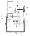
- a cleaner generally shown at 1, comprises a washing chamber 2 with an integral reservoir portion 3.
- the bottom and the top of the chamber 2 are connected by a circuit 4 comprising a pump 5 which sucks liquid from the reservoir 3 and pumps it into the chamber 2, in the direction of arrows a, through introduction means 6 which may comprise a plurality of spray heads or jets 7.
- the cleaner further comprises a wash tank 8 and a rinse tank 9 which are connected to the chamber 2 via respective valves 10, for example solenoid valves and a drain valve 11 which exhausts the reservoir 3 when operated.
- valves 10 for example solenoid valves and a drain valve 11 which exhausts the reservoir 3 when operated.
- items to be cleaned such as dental handpieces, syringes or the like, or indeed other surgical instruments and medical equipment, are placed on a tray immediately after use.
- a lid is placed on the tray sealing the items therein and the tray may be stored before cleaning.
- the tray is placed in the reservoir portion 3 of the chamber 2 with its lid removed and the door to the chamber 2 is shut and a cleaning cycle is started.
- the valve 10 associated with the wash tank 8 opens and washing liquid fills the reservoir 3.
- the pump 5 is then activated and circulates the washing liquid around the circuit 4.
- the pump 5 is deactivated and the drain valve 11 is opened, thereby draining the reservoir portion 3 of the washing liquid contained therein.
- the dirtied washing liquid, once evacuated, may be stored for disposal, filtered or otherwise treated and re-used, simply re-used or directly sent to waste.
- the drain valve 11 is closed and the valve 10 associated with the rinse tank 9 is opened. Rinsing liquid then fills the reservoir portion 3 to a pre-set level, at which time the valve 10 is closed and the pump 5 is activated to circulate the rinsing liquid around the circuit 4. At the end of a further pre-set time period, the pump 5 is deactivated and the drain valve 11 is activated thereby draining the reservoir 3 of rinsing fluid.
- the so-drained rinsing fluid may be similarly treated subsequent to its evacuation from the reservoir 3.
- the tray can then open the door to the chamber 2 and remove the tray with the cleaned items therein.
- the tray can then be placed in an autoclave, or other suitable means, where the items will be sterilised.
- the tray can then be removed from the sterilisation means and the items are conveniently ready for use.
- This cleaner obviously provides for a situation in which medical equipment, for example, is placed in the tray immediately after use and is then cleaned and sterilised, such that it is in a condition suitable for re-use, without anyone having to touch a single item. This substantially reduces the risk of sharps injuries and completely removes the opportunity for taking up of infectious agents spread through spatter from ultrasonic cleaners.
- inventive cleaner also provides a cheap, easily usable alternative to the systems currently employed and can be installed with nothing more than a supply of fluid and power.
- the washing fluid may comprise an enzyme solution, a bactericide, a disinfectant or a surfactant to help in the cleaning process and the rinsing fluid may contain a rinse aid to help in the removal of liquid from the items.
- a bespoke enzyme solution comprising one or more enzymes, which digests or breaks down any adhered matter is used.
- the solution may additionally or alternatively comprise a disinfectant to provide further microbiological decontamination of the items placed within the cleaner.
- the combination of the cleaning solution coupled with the action of the spray heads or jets 7 provides a fast and effective method of disinfecting surgical instruments.
- the pump 5 is of a power that flow rates around the circuit 4 are such that extensive cleaning and rinsing is undertaken during a respective two minute cycle. Under such conditions, any occluded or adhered matter may be removed from any items placed in the cleaner although the time period for each of the washing and rinsing cycles can be altered to suit the conditions of use.
- the cleaner may also comprise a heater 12 to heat any or all of the wash 8 and rinse 9 tanks or the reservoir 3 to promote the cleaning effect of the cleaner. It has been found that heating the washing fluid to around 80 °C is particularly efficacious in cleaning medical and other equipment.
- the introduction means 6 may comprise any number of spray heads or jets 7 which may impinge on the items to be cleaned from any direction, for example, at directions orthogonal from that shown in the diagram.
- the size of the reservoir 3 can be of a size such that a number of trays can be placed therein.
- retaining sliders can be fitted such that each pair of sliders supports one of a plurality of vertically situated trays to be accommodated within the reservoir and the trays may also be horizontally situated with respect to one another.
- Each of the functions of the cleaner may be controlled from an instrumental panel on the front of the machine. This enables an operator to select from a range of pre-determined washing cycles or programs or to manually select the time for each of the washing and rinsing cycles and a number of other parameters. For example, a particular type of instrument may require a greater flow rate of liquid or a higher operating temperature, or indeed a double wash cycle using two tanks of washing liquid with different washing liquids in each. All of the functions are controllable from the control panel.
Landscapes
- Health & Medical Sciences (AREA)
- General Health & Medical Sciences (AREA)
- Dentistry (AREA)
- Epidemiology (AREA)
- Life Sciences & Earth Sciences (AREA)
- Animal Behavior & Ethology (AREA)
- Oral & Maxillofacial Surgery (AREA)
- Public Health (AREA)
- Veterinary Medicine (AREA)
- Dental Tools And Instruments Or Auxiliary Dental Instruments (AREA)
- Apparatus For Disinfection Or Sterilisation (AREA)
- Filters For Electric Vacuum Cleaners (AREA)
- Cleaning By Liquid Or Steam (AREA)
Abstract
Description
- This invention relates to a cleaner and, more specifically, to a sealed cleaner which may be utilised to clean sharp or dangerous objects.
- Health-care workers, due to the nature of their employment, are often exposed to pathogens and other infectious organisms from the patients whom they treat and, therefore, are subjected to the possibility of contracting diseases. Indeed, it is well known that contact with such organisms represents a significant occupational hazard for such workers.
- Infection of a health-care worker may occur either directly or indirectly. Direct infection involves the transmission of, for example, a pathogen to a health-care worker, via a cut or abrasion on the workers skin, from infected bodily fluids of a patient. A variety of blood-bome diseases may be transmitted in such a fashion, for example HIV and Hepatitis, and consequently, as our knowledge of such transmission has increased, health-care workers have become more conscious of such risks. Disposable gloves are now used and many surgical or medical devices are disposed of by incineration after a single use.
- Indirect infection comes about through a pathway other than direct exposure to the infected bodily fluid of a patient. For example, a vector may provide the route of infection from its source to an individual. For health-care workers such vectors may include sharps, for example hypodermic needles, which can pierce the skin after they have been used and thereby infect the worker. In another case, a pathogen may become labile due to the medical procedure used and if, for example, the infection or its vector is vapourised during the procedure, it may be either directly ingested or may be deposited in such a position where it may be transmitted to a worker.
- It is well known that in dental practices dentists and dental nurses, as well as orthodontists and dental hygienists, may, in the course of their duties, find themselves in situations in which there is a potential for the transmission of infectious agents. A small ulcer or wound in the mouth of, for example, a patient can be the source of an infection. Indeed, it has been well established that many of the micro-organisms which are present in the mouth are pathogenic and, although they are usually kept under control by the body's own defence mechanisms, this is not always the case. Therefore, any broken skin of the health-care worker, which comes into direct or indirect contact with such a wound, will allow the possibility of direct transmission of infection or of an infectious agent.
- Furthermore, in dental practices there is an abundance of sharps which are routinely used and which are not disposable, that is to say, they are washed, disinfected, sterilised and then re-used. These, obviously, can provide a vector for indirect transmission as they may puncture the skin during use or whilst being cleaned. This route is therefore potentially serious and any attempt to mitigate this potential vector as a cause of infection is sought.
- However, there is another route of infection in dental practice which is potentially serious. Dental spatter and aerosols are produced when tools such as air turbine handpieces, ultrasonic scalers and three-in-one syringes are used. Dental spatter is defined as airborne particles comprising water, bacteria and other particulate matter and it has been known to contain living tubercle bacteria. This spatter may be found anywhere from six inches to four feet from the equipment used. Aerosols may be suspended in the air for long periods of time due to their size range which is nominally of the order of 0.5 - 50 µm.
- Although aerosols and dental spatter are produced whilst the equipment is in use, they may also be produced when the equipment is cleaned. Air powered tools are often connected to a pressure source in order to clean them and this can cause spatter. Also, it is known that conventional washing of infected or dirty equipment, such as by ultrasonic cleaning, can cause aerosol formation and spatter which may also spread infectious agents. In ultrasonic cleaners, for example, two pieces of equipment are often in contact with one another, such collisions can cause damage and, consequently, can be expensive. The cleaning of some equipment is not suitable for ultrasonic cleaning and, in such cases, occluded matter has to be scrubbed off of the equipment by hand. Obviously such an operation increases the likelihood of injury to the cleaner. Cleaned equipment is usually then placed in an autoclave where it is sterilised ready for its next use.
- The cleaning of dental and surgical equipment prior to its sterilisation has been previously considered. For example MERCK & Co (WO 94/02179) proposed a two stage method in which items to be cleaned are soaked in an enzyme solution and then soaked in a solution containing a germicidal detergent microbiological decontaminating composition. The total soak time is preferably 20 minutes for each step giving a total preferred soak time of 40 minutes. However, the disclosed method indicates that the use of gluteraldehyde, a known irritant, is preferred and the method does not provide for rinsing of the so-cleaned items. Moreover, the cleaning effect relies upon the efficacy of the cleaning system used and does not provide for agitation of the items to so aid in their cleansing, hence the elevated soak times.
- A.D.D. Co (WO 92/03171) have disclosed a hydro impact medical and dental instrument washer in which items to be cleaned are placed within holding means in a chamber, which is exposed to a turbulent flow of a liquid cleaning solution at a temperature in the range of 37 - 65 °C. The cleaning fluid is arranged to clean the items contained within the washer rather than to microbiologically disinfect them. Furthermore, the teachings do not provide for rinsing of the items once the matter has been removed therefrom and the provision of holding means ensures that a user handles the items subsequent to the cleaning process.
- Castellini S.p.A have proposed apparatus for cleaning surgical instruments (EP 0345228) in which surgical instruments, or at least the portion of which thought to be contaminated, are immersed in a cleaning solution, preferably comprising glutaraldehyde. A turbulent flow of liquid is produced by a dedicated compressed air line which is plumbed into the apparatus. The turbulent liquid flow is pulsed which necessitates the use of complicated valve systems and so on. The washing liquid and air are supplied from sources external to the tank and a preferred washing step of five hours is required for sterilisation, the apparatus being operated in through-flow mode.
- Siemens have suggested methods and apparatus for cleaning medical instruments (US 5723090 and US 5533539 respectively) in which items are cleaned by exposing them to a jet of cold water, followed by a jet of preheated water and cleaning the instruments with a heated water stream before lubricating and drying the items in a twenty minute cycle. Each of the fluids to which the items are exposed are supplied from dedicated external sources, necessitating the presence of sterile filters and oil separators for the air line, for example.
- Therefore it is an object of the invention to provide a cleaner which prevents or, at least, substantially reduces the chance of infection when cleaning infected or at least potentially infected objects such as sharps other dental tools or surgical instruments and provides a safe method of carrying out such a cleaning operation whilst avoiding the problems associated with prior art cleaners, such as elevated cleaning times, the provision of external sources of cleaning materials necessitating dedicated supply lines and the like. Moreover, it is an object to provide a cleaner in which a minimum of materials are required to facilitate the cleaning of fouled or dirtied surgical instruments, such as relatively low water and power consumption.
- It is a further object of the invention to provide a cleaner which can clean surgical instruments which have been previously located in a standard autoclave tray such that the operator need not come into contact with any such items after their use and until their storage prior to their next use.
- Accordingly, the invention provides a dental equipment cleaning apparatus comprising a washing chamber, a washing tank arranged to supply the chamber with washing liquid, a rinsing tank arranged to supply the chamber with rinsing liquid and circulation means, wherein washing liquid is arranged to circulate by said circulation means around a circuit comprising the chamber for a given time period and drain means arranged to drain the chamber of liquid once circulation has ceased, and wherein said circulation means is arranged to circulate rinsing liquid introduced into the chamber from the rinsing tank.
- The chamber may comprise a reservoir portion holding a volume of liquid during a respective cleaning cycle, and in which, in use, dental equipment to be cleaned is situated. Preferably the dental equipment is placed in a tray before it is placed in the reservoir. The tray may be autoclavable. Additionally, the washing liquid may comprise an enzyme and/or a bactericide and/or a surfactant and/or a disinfectant and the rinsing liquid may comprise a rinse aid.
- The time period for each of the washing and rinsing cycles is preferably less than fifteen minutes, more preferably less than ten minutes and more preferably still less that five minutes duration. In a preferred embodiment the flow rate is such that all adhered or occluded matter is removed from the dental equipment within two minutes of commencement of the washing cycle.
- Introducing means, preferably comprising jets, may be provided for introducing the respective liquids into the chamber. Also, means for heating the washing liquid and/or rinsing liquid and/or at least a portion of the chamber, may be included.
- Further, there may be provided a method of cleaning dental equipment comprising providing apparatus in accordance with the invention, as defined above, placing dental equipment to be cleaned in the washing chamber (2), circulating washing liquid around a circuit comprising the chamber for a given time period, draining the chamber (2) of washing liquid once circulation has ceased and circulating rinsing liquid introduced into the chamber (2) subsequent to completion of washing.
- The invention will now be described with reference to the accompanying drawing which shows a schematic diagram of the cleaner.
- A cleaner, generally shown at 1, comprises a washing chamber 2 with an integral reservoir portion 3. The bottom and the top of the chamber 2 are connected by a
circuit 4 comprising a pump 5 which sucks liquid from the reservoir 3 and pumps it into the chamber 2, in the direction of arrows a, through introduction means 6 which may comprise a plurality of spray heads or jets 7. - The cleaner further comprises a wash tank 8 and a rinse tank 9 which are connected to the chamber 2 via
respective valves 10, for example solenoid valves and adrain valve 11 which exhausts the reservoir 3 when operated. - In operation, items to be cleaned, such as dental handpieces, syringes or the like, or indeed other surgical instruments and medical equipment, are placed on a tray immediately after use. A lid is placed on the tray sealing the items therein and the tray may be stored before cleaning. The tray is placed in the reservoir portion 3 of the chamber 2 with its lid removed and the door to the chamber 2 is shut and a cleaning cycle is started.
- The
valve 10 associated with the wash tank 8 opens and washing liquid fills the reservoir 3. The pump 5 is then activated and circulates the washing liquid around thecircuit 4. At the end of a pre-set time period, which is preferably about two minutes, the pump 5 is deactivated and thedrain valve 11 is opened, thereby draining the reservoir portion 3 of the washing liquid contained therein. The dirtied washing liquid, once evacuated, may be stored for disposal, filtered or otherwise treated and re-used, simply re-used or directly sent to waste. - Once the reservoir portion 3 is drained of dirtied washing liquid the
drain valve 11 is closed and thevalve 10 associated with the rinse tank 9 is opened. Rinsing liquid then fills the reservoir portion 3 to a pre-set level, at which time thevalve 10 is closed and the pump 5 is activated to circulate the rinsing liquid around thecircuit 4. At the end of a further pre-set time period, the pump 5 is deactivated and thedrain valve 11 is activated thereby draining the reservoir 3 of rinsing fluid. The so-drained rinsing fluid may be similarly treated subsequent to its evacuation from the reservoir 3. - An operator may then open the door to the chamber 2 and remove the tray with the cleaned items therein. The tray can then be placed in an autoclave, or other suitable means, where the items will be sterilised. The tray can then be removed from the sterilisation means and the items are conveniently ready for use.
- This cleaner obviously provides for a situation in which medical equipment, for example, is placed in the tray immediately after use and is then cleaned and sterilised, such that it is in a condition suitable for re-use, without anyone having to touch a single item. This substantially reduces the risk of sharps injuries and completely removes the opportunity for taking up of infectious agents spread through spatter from ultrasonic cleaners.
- Furthermore the inventive cleaner also provides a cheap, easily usable alternative to the systems currently employed and can be installed with nothing more than a supply of fluid and power.
- The washing fluid may comprise an enzyme solution, a bactericide, a disinfectant or a surfactant to help in the cleaning process and the rinsing fluid may contain a rinse aid to help in the removal of liquid from the items.
- Indeed, in a preferred embodiment a bespoke enzyme solution, comprising one or more enzymes, which digests or breaks down any adhered matter is used. The solution may additionally or alternatively comprise a disinfectant to provide further microbiological decontamination of the items placed within the cleaner. The combination of the cleaning solution coupled with the action of the spray heads or jets 7 provides a fast and effective method of disinfecting surgical instruments.
- The pump 5 is of a power that flow rates around the
circuit 4 are such that extensive cleaning and rinsing is undertaken during a respective two minute cycle. Under such conditions, any occluded or adhered matter may be removed from any items placed in the cleaner although the time period for each of the washing and rinsing cycles can be altered to suit the conditions of use. Furthermore the cleaner may also comprise aheater 12 to heat any or all of the wash 8 and rinse 9 tanks or the reservoir 3 to promote the cleaning effect of the cleaner. It has been found that heating the washing fluid to around 80 °C is particularly efficacious in cleaning medical and other equipment. - The introduction means 6 may comprise any number of spray heads or jets 7 which may impinge on the items to be cleaned from any direction, for example, at directions orthogonal from that shown in the diagram.
- Moreover, the size of the reservoir 3 can be of a size such that a number of trays can be placed therein. For example retaining sliders can be fitted such that each pair of sliders supports one of a plurality of vertically situated trays to be accommodated within the reservoir and the trays may also be horizontally situated with respect to one another.
- Each of the functions of the cleaner may be controlled from an instrumental panel on the front of the machine. This enables an operator to select from a range of pre-determined washing cycles or programs or to manually select the time for each of the washing and rinsing cycles and a number of other parameters. For example, a particular type of instrument may require a greater flow rate of liquid or a higher operating temperature, or indeed a double wash cycle using two tanks of washing liquid with different washing liquids in each. All of the functions are controllable from the control panel.
- Thus, there is provided an easy to use cleaner with minimal installation costs and low overheads and one which substantially reduces the possibility of injury to an operator whilst cleaning.
Claims (12)
- A dental equipment cleaning apparatus (1) comprising a washing chamber (2), a washing tank (8) arranged to supply the chamber (2) with washing liquid, a rinsing tank (9) arranged to supply the chamber (2) with rinsing liquid and circulation means (4, 5), wherein washing liquid is arranged to circulate by said circulation means (4, 5) around a circuit comprising the chamber (2) for a given time period and drain means (11) arranged to drain the chamber (2) of liquid once circulation has ceased, and wherein said circulation means (4, 5) is arranged to circulate rinsing liquid introduced into the chamber (2) from the rinsing tank (9) subsequent to completion of the washing cycle.
- Apparatus (1) according to claim 1, wherein the chamber (2) comprises a reservoir portion (3) holding a volume of liquid during a respective cleaning cycle, and in which, in use, dental equipment to be cleaned is situated.
- Apparatus (1) according to claim 2 further comprising a tray which is located or locatable within the reservoir (3) and in which, in use, the dental equipment is placed or placeable.
- Apparatus (1) according to claim 3, wherein the tray is an autoclavable tray.
- Apparatus (1) according to any preceding claim, wherein the washing liquid comprises an enzyme and/or a bactericide and/or a surfactant and/or a disinfectant.
- Apparatus (1) according to any preceding claim, wherein the rinsing liquid comprises a rinse aid.
- Apparatus (1) according to any preceding claim, wherein the time period for each of the washing and rinsing cycles is less than fifteen minutes, more preferably less than ten minutes and more preferably still less that five minutes duration.
- Apparatus (1) according to any preceding claim further comprising introducing means (6) to introduce the respective liquids into the chamber (2).
- Apparatus (1) according to claim 8, wherein said introducing means (6) comprises jets (7).
- Apparatus (1) according to any preceding claim, wherein the flow rate of washing liquid is such that all occluded or adhered matter is removed from the dental equipment within two minutes of commencement of the washing cycle.
- Apparatus (1) according to any preceding claim further comprising heating means (12) arranged to heat the washing liquid and/or rinsing liquid and/or at least a portion of the chamber (2).
- A method of cleaning dental equipment comprising providing apparatus according to any preceding claim, placing dental equipment to be cleaned in the washing chamber, circulating washing liquid around a circuit comprising the chamber for a given time period, draining the chamber of washing liquid once circulation has ceased and circulating rinsing liquid introduced into the chamber subsequent to completion of washing.
Applications Claiming Priority (2)
| Application Number | Priority Date | Filing Date | Title |
|---|---|---|---|
| GBGB9914391.9A GB9914391D0 (en) | 1999-06-22 | 1999-06-22 | Cleaner |
| GB9914391 | 1999-06-22 |
Publications (3)
| Publication Number | Publication Date |
|---|---|
| EP1062918A2 EP1062918A2 (en) | 2000-12-27 |
| EP1062918A3 EP1062918A3 (en) | 2002-12-18 |
| EP1062918B1 true EP1062918B1 (en) | 2006-01-11 |
Family
ID=10855711
Family Applications (1)
| Application Number | Title | Priority Date | Filing Date |
|---|---|---|---|
| EP00305326A Expired - Lifetime EP1062918B1 (en) | 1999-06-22 | 2000-06-22 | Apparatus for cleaning dental equipment |
Country Status (4)
| Country | Link |
|---|---|
| EP (1) | EP1062918B1 (en) |
| AT (1) | ATE315364T1 (en) |
| DE (1) | DE60025441T2 (en) |
| GB (2) | GB9914391D0 (en) |
Families Citing this family (1)
| Publication number | Priority date | Publication date | Assignee | Title |
|---|---|---|---|---|
| DE102005001700A1 (en) * | 2005-01-13 | 2006-07-27 | Julius-Maximilians-Universität Würzburg | Instrument cleaning device for treatment instruments |
Family Cites Families (9)
| Publication number | Priority date | Publication date | Assignee | Title |
|---|---|---|---|---|
| DE3430605A1 (en) * | 1984-08-20 | 1986-02-27 | Siemens AG, 1000 Berlin und 8000 München | METHOD AND DEVICE FOR CLEANING, DISINFECTING AND STERILIZING MEDICAL, IN PARTICULAR DENTAL, INSTRUMENTS |
| US5137689A (en) * | 1987-07-01 | 1992-08-11 | Cantrell Stephen B | Method and apparatus for cleaning instruments |
| IT1220367B (en) * | 1988-05-17 | 1990-06-15 | Castellini Spa | METHOD AND EQUIPMENT FOR THE STERILIZATION AND MECHANICAL CLEANING OF MEDICAL, SURGICAL AND DENTAL TOOLS SUCH AS HANDPIECES, MIRRORS, SCALPEL AND SIMILAR |
| EP0544762A4 (en) * | 1990-08-20 | 1995-01-11 | A.D.D. Co. | Hydro impact medical and dental instruments washer |
| CA2052649A1 (en) * | 1990-10-15 | 1992-04-16 | Steris Inc. | Combined two stage method for cleaning and decontaminating surgical instruments |
| US5489531A (en) | 1990-10-15 | 1996-02-06 | E. R. Squibb And Sons, Inc. | Combined two stage method for cleaning and decontaminating surgical instruments |
| CA2127907C (en) | 1993-07-15 | 2006-07-11 | Ralf Sutter | Method and apparatus for intensive cleaning of medical articles |
| DE4323815C2 (en) | 1993-07-15 | 1997-09-25 | Siemens Ag | Method and device for the hygienic preparation of medical, in particular dental, instruments |
| SE507213C2 (en) * | 1996-06-18 | 1998-04-27 | Tsp Medical Ab | Device for sterilizing instruments |
-
1999
- 1999-06-22 GB GBGB9914391.9A patent/GB9914391D0/en not_active Ceased
-
2000
- 2000-06-22 DE DE60025441T patent/DE60025441T2/en not_active Expired - Fee Related
- 2000-06-22 AT AT00305326T patent/ATE315364T1/en not_active IP Right Cessation
- 2000-06-22 GB GB0015160A patent/GB2351226A/en not_active Withdrawn
- 2000-06-22 EP EP00305326A patent/EP1062918B1/en not_active Expired - Lifetime
Also Published As
| Publication number | Publication date |
|---|---|
| ATE315364T1 (en) | 2006-02-15 |
| DE60025441D1 (en) | 2006-04-06 |
| GB0015160D0 (en) | 2000-08-09 |
| GB2351226A (en) | 2000-12-27 |
| EP1062918A3 (en) | 2002-12-18 |
| GB9914391D0 (en) | 1999-08-18 |
| DE60025441T2 (en) | 2006-09-21 |
| EP1062918A2 (en) | 2000-12-27 |
Similar Documents
| Publication | Publication Date | Title |
|---|---|---|
| US5245845A (en) | Flexible article sterilizing mechanism | |
| US5443801A (en) | Endoscope cleaner/sterilizer | |
| KR20010024138A (en) | Sterilization Using Liquid Carbon Dioxide and UV-Irradiation | |
| JP7332174B2 (en) | Apparatus for cleaning surgical instruments and medical devices generally and procedures for pre-treating surgical instruments and medical devices | |
| Rani | Sterilization protocols in dentistry-A review | |
| Sanchez et al. | Decontaminating dental instruments: testing the effectiveness of selected methods | |
| CA2519931A1 (en) | Supplemental ozone treatment methods for difficult cleaning and sterilizing applications | |
| AU752509B2 (en) | Method and device for disinfection/sterilization of medical instruments | |
| US6346218B1 (en) | Pliable container for treatment of infectious medical waste | |
| JP4469577B2 (en) | Cleaning and disinfecting treatment equipment | |
| EP1062918B1 (en) | Apparatus for cleaning dental equipment | |
| Bhatnagar et al. | Infection control strategy in orthodontic office | |
| Savage et al. | The use of autoclaves in the dental surgery | |
| GB2500866A (en) | Method for decontamination of medical instruments | |
| KR20010111031A (en) | A method for sterilising conduits that convey fluid to medical instruments, especially dental instruments | |
| KR200216082Y1 (en) | Apparatus For Sterilizing and Cleaning Of Medical Instruments | |
| JPH06509482A (en) | Sterilization method and equipment | |
| JPH01305956A (en) | Sterilizing and rinsing method | |
| JPH0731636A (en) | Medical fluid spray type washing sterilizer of handpiece for dental cutting | |
| RU2041719C1 (en) | Medical purpose articles postoperative treatment method | |
| Mohamed et al. | Sterilization | |
| DK200700139U3 (en) | Apparatus for sterilizing an element | |
| JPH0241161A (en) | Method and apparatus for purifying instrument | |
| CN110404093B (en) | Washing, disinfecting, drying and/or sterilizing apparatus, and associated method and medium | |
| Porter | Focus on decontamination: legislation and equipment |
Legal Events
| Date | Code | Title | Description |
|---|---|---|---|
| PUAI | Public reference made under article 153(3) epc to a published international application that has entered the european phase |
Free format text: ORIGINAL CODE: 0009012 |
|
| AK | Designated contracting states |
Kind code of ref document: A2 Designated state(s): AT BE CH CY DE DK ES FI FR GB GR IE IT LI LU MC NL PT SE |
|
| AX | Request for extension of the european patent |
Free format text: AL;LT;LV;MK;RO;SI |
|
| PUAL | Search report despatched |
Free format text: ORIGINAL CODE: 0009013 |
|
| AK | Designated contracting states |
Kind code of ref document: A3 Designated state(s): AT BE CH CY DE DK ES FI FR GB GR IE IT LI LU MC NL PT SE |
|
| AX | Request for extension of the european patent |
Free format text: AL;LT;LV;MK;RO;SI |
|
| 17P | Request for examination filed |
Effective date: 20030516 |
|
| AKX | Designation fees paid |
Designated state(s): AT BE CH CY DE DK ES FI FR GB GR IE IT LI LU MC NL PT SE |
|
| 17Q | First examination report despatched |
Effective date: 20040929 |
|
| GRAP | Despatch of communication of intention to grant a patent |
Free format text: ORIGINAL CODE: EPIDOSNIGR1 |
|
| GRAS | Grant fee paid |
Free format text: ORIGINAL CODE: EPIDOSNIGR3 |
|
| GRAA | (expected) grant |
Free format text: ORIGINAL CODE: 0009210 |
|
| AK | Designated contracting states |
Kind code of ref document: B1 Designated state(s): AT BE CH CY DE DK ES FI FR GB GR IE IT LI LU MC NL PT SE |
|
| PG25 | Lapsed in a contracting state [announced via postgrant information from national office to epo] |
Ref country code: BE Free format text: LAPSE BECAUSE OF FAILURE TO SUBMIT A TRANSLATION OF THE DESCRIPTION OR TO PAY THE FEE WITHIN THE PRESCRIBED TIME-LIMIT Effective date: 20060111 Ref country code: NL Free format text: LAPSE BECAUSE OF FAILURE TO SUBMIT A TRANSLATION OF THE DESCRIPTION OR TO PAY THE FEE WITHIN THE PRESCRIBED TIME-LIMIT Effective date: 20060111 Ref country code: AT Free format text: LAPSE BECAUSE OF FAILURE TO SUBMIT A TRANSLATION OF THE DESCRIPTION OR TO PAY THE FEE WITHIN THE PRESCRIBED TIME-LIMIT Effective date: 20060111 Ref country code: FI Free format text: LAPSE BECAUSE OF FAILURE TO SUBMIT A TRANSLATION OF THE DESCRIPTION OR TO PAY THE FEE WITHIN THE PRESCRIBED TIME-LIMIT Effective date: 20060111 Ref country code: CH Free format text: LAPSE BECAUSE OF FAILURE TO SUBMIT A TRANSLATION OF THE DESCRIPTION OR TO PAY THE FEE WITHIN THE PRESCRIBED TIME-LIMIT Effective date: 20060111 Ref country code: LI Free format text: LAPSE BECAUSE OF FAILURE TO SUBMIT A TRANSLATION OF THE DESCRIPTION OR TO PAY THE FEE WITHIN THE PRESCRIBED TIME-LIMIT Effective date: 20060111 |
|
| REG | Reference to a national code |
Ref country code: CH Ref legal event code: EP |
|
| REG | Reference to a national code |
Ref country code: IE Ref legal event code: FG4D |
|
| REF | Corresponds to: |
Ref document number: 60025441 Country of ref document: DE Date of ref document: 20060406 Kind code of ref document: P |
|
| PG25 | Lapsed in a contracting state [announced via postgrant information from national office to epo] |
Ref country code: DK Free format text: LAPSE BECAUSE OF FAILURE TO SUBMIT A TRANSLATION OF THE DESCRIPTION OR TO PAY THE FEE WITHIN THE PRESCRIBED TIME-LIMIT Effective date: 20060411 Ref country code: SE Free format text: LAPSE BECAUSE OF FAILURE TO SUBMIT A TRANSLATION OF THE DESCRIPTION OR TO PAY THE FEE WITHIN THE PRESCRIBED TIME-LIMIT Effective date: 20060411 |
|
| PG25 | Lapsed in a contracting state [announced via postgrant information from national office to epo] |
Ref country code: ES Free format text: LAPSE BECAUSE OF FAILURE TO SUBMIT A TRANSLATION OF THE DESCRIPTION OR TO PAY THE FEE WITHIN THE PRESCRIBED TIME-LIMIT Effective date: 20060422 |
|
| PGFP | Annual fee paid to national office [announced via postgrant information from national office to epo] |
Ref country code: GB Payment date: 20060608 Year of fee payment: 7 |
|
| PG25 | Lapsed in a contracting state [announced via postgrant information from national office to epo] |
Ref country code: PT Free format text: LAPSE BECAUSE OF FAILURE TO SUBMIT A TRANSLATION OF THE DESCRIPTION OR TO PAY THE FEE WITHIN THE PRESCRIBED TIME-LIMIT Effective date: 20060612 |
|
| PG25 | Lapsed in a contracting state [announced via postgrant information from national office to epo] |
Ref country code: IE Free format text: LAPSE BECAUSE OF NON-PAYMENT OF DUE FEES Effective date: 20060622 |
|
| PGFP | Annual fee paid to national office [announced via postgrant information from national office to epo] |
Ref country code: DE Payment date: 20060624 Year of fee payment: 7 |
|
| PGFP | Annual fee paid to national office [announced via postgrant information from national office to epo] |
Ref country code: FR Payment date: 20060628 Year of fee payment: 7 |
|
| PG25 | Lapsed in a contracting state [announced via postgrant information from national office to epo] |
Ref country code: MC Free format text: LAPSE BECAUSE OF NON-PAYMENT OF DUE FEES Effective date: 20060630 |
|
| PGFP | Annual fee paid to national office [announced via postgrant information from national office to epo] |
Ref country code: IT Payment date: 20060630 Year of fee payment: 7 |
|
| NLV1 | Nl: lapsed or annulled due to failure to fulfill the requirements of art. 29p and 29m of the patents act | ||
| REG | Reference to a national code |
Ref country code: CH Ref legal event code: PL |
|
| ET | Fr: translation filed | ||
| REG | Reference to a national code |
Ref country code: GB Ref legal event code: 732E |
|
| PLBE | No opposition filed within time limit |
Free format text: ORIGINAL CODE: 0009261 |
|
| STAA | Information on the status of an ep patent application or granted ep patent |
Free format text: STATUS: NO OPPOSITION FILED WITHIN TIME LIMIT |
|
| 26N | No opposition filed |
Effective date: 20061012 |
|
| GBPC | Gb: european patent ceased through non-payment of renewal fee |
Effective date: 20070622 |
|
| REG | Reference to a national code |
Ref country code: FR Ref legal event code: ST Effective date: 20080229 |
|
| PG25 | Lapsed in a contracting state [announced via postgrant information from national office to epo] |
Ref country code: GR Free format text: LAPSE BECAUSE OF FAILURE TO SUBMIT A TRANSLATION OF THE DESCRIPTION OR TO PAY THE FEE WITHIN THE PRESCRIBED TIME-LIMIT Effective date: 20060412 Ref country code: DE Free format text: LAPSE BECAUSE OF NON-PAYMENT OF DUE FEES Effective date: 20080101 |
|
| PG25 | Lapsed in a contracting state [announced via postgrant information from national office to epo] |
Ref country code: GB Free format text: LAPSE BECAUSE OF NON-PAYMENT OF DUE FEES Effective date: 20070622 |
|
| REG | Reference to a national code |
Ref country code: GB Ref legal event code: 732E |
|
| PG25 | Lapsed in a contracting state [announced via postgrant information from national office to epo] |
Ref country code: LU Free format text: LAPSE BECAUSE OF NON-PAYMENT OF DUE FEES Effective date: 20060622 |
|
| PG25 | Lapsed in a contracting state [announced via postgrant information from national office to epo] |
Ref country code: FR Free format text: LAPSE BECAUSE OF NON-PAYMENT OF DUE FEES Effective date: 20070702 |
|
| PG25 | Lapsed in a contracting state [announced via postgrant information from national office to epo] |
Ref country code: CY Free format text: LAPSE BECAUSE OF FAILURE TO SUBMIT A TRANSLATION OF THE DESCRIPTION OR TO PAY THE FEE WITHIN THE PRESCRIBED TIME-LIMIT Effective date: 20060111 |
|
| PG25 | Lapsed in a contracting state [announced via postgrant information from national office to epo] |
Ref country code: IT Free format text: LAPSE BECAUSE OF NON-PAYMENT OF DUE FEES Effective date: 20070622 |