EP1059420A1 - Housing for a high pressure compressor - Google Patents
Housing for a high pressure compressor Download PDFInfo
- Publication number
- EP1059420A1 EP1059420A1 EP00401609A EP00401609A EP1059420A1 EP 1059420 A1 EP1059420 A1 EP 1059420A1 EP 00401609 A EP00401609 A EP 00401609A EP 00401609 A EP00401609 A EP 00401609A EP 1059420 A1 EP1059420 A1 EP 1059420A1
- Authority
- EP
- European Patent Office
- Prior art keywords
- ventilation
- ferrule
- sectors
- rings
- stator according
- Prior art date
- Legal status (The legal status is an assumption and is not a legal conclusion. Google has not performed a legal analysis and makes no representation as to the accuracy of the status listed.)
- Granted
Links
Images


Classifications
-
- F—MECHANICAL ENGINEERING; LIGHTING; HEATING; WEAPONS; BLASTING
- F01—MACHINES OR ENGINES IN GENERAL; ENGINE PLANTS IN GENERAL; STEAM ENGINES
- F01D—NON-POSITIVE DISPLACEMENT MACHINES OR ENGINES, e.g. STEAM TURBINES
- F01D11/00—Preventing or minimising internal leakage of working-fluid, e.g. between stages
- F01D11/08—Preventing or minimising internal leakage of working-fluid, e.g. between stages for sealing space between rotor blade tips and stator
- F01D11/14—Adjusting or regulating tip-clearance, i.e. distance between rotor-blade tips and stator casing
- F01D11/16—Adjusting or regulating tip-clearance, i.e. distance between rotor-blade tips and stator casing by self-adjusting means
- F01D11/18—Adjusting or regulating tip-clearance, i.e. distance between rotor-blade tips and stator casing by self-adjusting means using stator or rotor components with predetermined thermal response, e.g. selective insulation, thermal inertia, differential expansion
-
- F—MECHANICAL ENGINEERING; LIGHTING; HEATING; WEAPONS; BLASTING
- F04—POSITIVE - DISPLACEMENT MACHINES FOR LIQUIDS; PUMPS FOR LIQUIDS OR ELASTIC FLUIDS
- F04D—NON-POSITIVE-DISPLACEMENT PUMPS
- F04D29/00—Details, component parts, or accessories
- F04D29/40—Casings; Connections of working fluid
- F04D29/52—Casings; Connections of working fluid for axial pumps
- F04D29/54—Fluid-guiding means, e.g. diffusers
- F04D29/541—Specially adapted for elastic fluid pumps
- F04D29/545—Ducts
Landscapes
- Engineering & Computer Science (AREA)
- Mechanical Engineering (AREA)
- General Engineering & Computer Science (AREA)
- Structures Of Non-Positive Displacement Pumps (AREA)
Abstract
Description
Le sujet de cette invention est un stator à structure hétérogène susceptible de s'appliquer en particulier aux compresseurs à haute pression de turbines à gaz.The subject of this invention is a stator heterogeneous structure likely to apply in particular to high pressure compressors of gas turbines.
La structure du rotor et du stator des turbines à gaz est souvent refroidie ou ventilée par de l'air prélevé de l'écoulement qui parcourt la machine. On rencontre même des doubles ventilations associées à des doubles prélèvements, où une ventilation d'une partie aval du stator et du rotor fait suite à une première ventilation du stator et du rotor effectuée plus en amont. L'air prélevé pour la ventilation en aval est originaire d'une partie de la machine où il a déjà été comprimé, ce qui l'a beaucoup plus échauffé que l'air de la ventilation en amont. Le problème habituel d'obtenir un réglage correct des diamètres du stator et du rotor afin d'éviter l'augmentation excessive des jeux au bout des aubes, qui accroítrait les fuites d'air et les pertes de rendement, ou au contraire la disparition de ces jeux, qui aurait pour conséquence un frottement des aubes du rotor sur le stator, devient alors bien difficile à résoudre à cause de ces conditions hétérogènes de ventilation, qui induisent des températures et des dilatations thermiques différentes entre les portions respectivement soumises aux deux ventilations. Une autre source de difficultés provient de ce que les différentes parties de la machine, même celles qui sont situées à un même niveau du compresseur, sont portées à des températures différentes selon qu'elles sont proches de l'air de ventilation ou de l'air plus chaud de la veine d'écoulement : il en résulte des dilatations inégales, des déformations et des contraintes dans le stator. Enfin, les variations de température sont plus rapides à certains endroits, de sorte que les problèmes précédents peuvent devenir plus ou moins aigus localement, pendant les phases de changement de régime. Aucune structure connue de stator ne donne entière satisfaction dans ces conditions.The rotor and stator structure of gas turbine is often cooled or ventilated by the air taken from the flow which flows through the machine. There are even double breakdowns associated with double samples, where a breakdown of a downstream part of the stator and rotor follows a first ventilation of the stator and rotor carried out further upstream. The air taken for ventilation in downstream comes from a part of the machine where it has already been compressed, which made it much warmer than the air from the upstream ventilation. The problem usual to obtain a correct setting of the diameters of the stator and rotor to avoid increase excessive play at the tip of the blades, which would increase air leaks and performance losses, or at otherwise the disappearance of these games, which would consequently a friction of the blades of the rotor on the stator, becomes very difficult to resolve because of these heterogeneous ventilation conditions, which induce temperatures and expansions different thermals between the portions respectively subject to the two breakdowns. A another source of difficulty is that the different parts of the machine, even those that are located on the same level of the compressor, are brought to different temperatures depending on whether they are close to ventilation air or warmer air flow vein: this results in unequal dilations, deformations and constraints in the stator. Finally, variations in temperatures are faster in some places, so the previous problems may become more or less acute locally, during the phases of change of regime. No known stator structure is not entirely satisfactory under these conditions.
L'idée de l'invention consiste à scinder la structure du stator de part et d'autre de la jonction des zones de ventilations et de construire différemment le stator entre les portions soumises à la ventilation en amont et celles qui sont soumises à la ventilation en aval. Sous sa forme la plus générale, l'invention consiste en un stator de compresseur muni d'une ventilation en amont et une ventilation en aval d'air plus chaud qu'à la ventilation amont et comprenant une virole délimitant une veine d'écoulement de gaz, caractérisé en ce qu'il comprend une première portion de virole, soumise à la ventilation en amont, à structure annulaire continue sur une circonférence et en un premier matériau, et une deuxième portion de virole, soumise à la ventilation aval, à structure formée de secteurs angulaires juxtaposés et en un deuxième matériau ayant un coefficient de dilatation plus grand que le premier matériau. The idea of the invention is to split the stator structure on either side of the junction ventilation zones and build differently the stator between the portions subjected to ventilation upstream and those subject to ventilation downstream. In its most general form, the invention consists of a compressor stator fitted with a upstream ventilation and downstream ventilation warmer than upstream ventilation and including a ferrule defining a gas flow stream, characterized in that it comprises a first portion ferrule, subject to upstream ventilation, to continuous ring structure on a circumference and in a first material, and a second portion of ferrule, subjected to downstream ventilation, with structure formed of juxtaposed angular sectors and in one second material having a coefficient of expansion larger than the first material.
Les premier et deuxième matériaux peuvent être choisis, respectivement parmi des matériaux à coefficient de dilatation plus bas tels que TA6V et alliages de titane, INC0909, intermétalliques du type TiAl, ayant un coefficient moyen de dilatation linéique inférieur à 10.10-6 m par degré ; et parmi des matériaux à coefficient de dilatation plus grand tels que des alliages à base de nickel du type INC0718, RENE77 et dérivés, ayant un coefficient moyen de dilatation linéique voisin de 15.10-6 m par degré.The first and second materials can be chosen, respectively, from materials with a lower coefficient of expansion such as TA6V and titanium alloys, INC0909, intermetallic of the TiAl type, having an average coefficient of linear expansion of less than 10.10 -6 m per degree; and among materials with a greater coefficient of expansion such as nickel-based alloys of the type INC0718, RENE77 and derivatives, having an average coefficient of linear expansion close to 15.10 -6 m per degree.
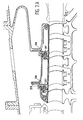
Une explication plus détaillée de l'invention, de ses caractéristiques, buts et avantages sera fournie à l'aide des figures, dont la figure 1 est une vue d'ensemble d'un compresseur à haute pression d'une turbine à gaz ; la figure 2 est une vue agrandie de la partie aval du stator de ce compresseur ; la figure 2A une vue analogue d'une autre réalisation possible de l'invention ; les figures 3 et 4 sont deux coupes de la partie amont et de la partie aval du compresseur ; et la figure 5 est une vue agrandie de la partie amont du compresseur.A more detailed explanation of the invention, its characteristics, aims and advantages will be provided using the figures, of which figure 1 is an overview of a high pressure compressor a gas turbine; Figure 2 is an enlarged view the downstream part of the stator of this compressor; the Figure 2A a similar view of another embodiment possible of the invention; Figures 3 and 4 are two sections of the upstream part and the downstream part of the compressor; and Figure 5 is an enlarged view of the upstream part of the compressor.
Un compresseur à haute pression tel que
celui de la figure 1 comprend un rotor central 1
entraíné par une ligne d'arbres 2 et composé d'une
enveloppe 3 de forme fuselée composée d'anneaux 4
juxtaposés et séparés par des disques 5 au droit
d'étages d'aubes mobiles 6. Un stator 7 entoure le
rotor 1 et comprend, en doublure interne d'une carcasse
8, une portion 9 sur laquelle porte l'invention et qui
se compose d'un carter 10 de support et d'une virole 11
soutenue par le carter 10, tournée vers le rotor 1 et
qui sert à délimiter une veine 12 annulaire
d'écoulement des gaz dans laquelle s'étendent les
étages d'aubes mobiles 6 et des étages d'aubes
stationnaires 13 de redressement de l'écoulement, qui
sont accrochés à la virole 11 et alternent avec les
étages précédemment mentionnés. Il est habituel que les
bouts des aubes stationnaires 13, situés devant
l'enveloppe 3 du rotor 1, portent des anneaux de
liaison 14 garnis de bandes circulaires de matière dite
abradable 15, formée d'une structure en nid d'abeilles
ou plus généralement d'érosion facile, qui est creusée
par des nervures 16 en regard érigées sur l'enveloppe 3
et qui forment avec elle un joint d'étanchéité à
labyrinthe. Cependant, les bouts des aubes mobiles 6
sont libres de tout équipement et finissent tout près
de la virole 11.A high pressure compressor such as
that of FIG. 1 comprises a central rotor 1
driven by a line of trees 2 and composed of a
envelope 3 of tapered shape composed of
La portion 9 interne du stator 7 présente
des discontinuités, qui sont des ouvertures de
prélèvement d'air de la veine 12, notées par les
références 17, 18 et qui donnent dans des chambres
respectives 19 et 20 établies entre la portion 9 et la
carcasse 8 et par lesquelles transite l'air prélevé de
la veine 12 pour ventiler en particulier le carter 10
et le soumettre à une température et une dilatation
thermique déterminée. L'intérieur du rotor 1 est lui
aussi ventilé, tout d'abord à travers un perçage 21 de
l'enveloppe 3 situé en amont du rotor 1 et par lequel
de l'air frais, sensiblement à la même température que
celui qui entre dans la chambre 19, est aspiré, puis
par un autre perçage 22 de l'enveloppe 3, sensiblement
au droit de la deuxième ouverture 18. Les chambres 19
et 20 divisent la stator 7 en deux zones de
ventilation, devant lesquelles elles s'étendent
respectivement et qui sont situées de part et d'autre
de l'ouverture 19 d'entrée dans la chambre aval 20, qui
sépare la portion 9 en deux. Deux zones de ventilation
de positions semblables existent sur le rotor 1, de
part et d'autre du perçage 22.The
Malgré les précautions prises pour égaliser
les dilatations thermiques entre les diverses parties
du rotor 1 et du stator 7, notamment en prévoyant pour
chacun d'eux des conditions de ventilation identiques,
l'expérience montre qu'on est embarrassé pour trouver
des conditions de fonctionnement satisfaisantes, en ne
laissant subsister que des jeux modérés entre les aubes
mobiles 6 et la virole 11. Le problème est plus aigu
pour la partie aval, parcourue par de l'air plus chaud
et soumise à une ventilation également plus chaude. On
préconise alors (figures 2 et 3) de construire la
virole 11 sous forme de secteurs 23, dont on peut
trouver un nombre variable sur une circonférence, peut-être
une dizaine, et dont l'extension longitudinale
peut aussi être variable ; dans le cas présent, on
propose deux cercles de secteurs 23 présentant une
partie avant de support d'aube stationnaire 13 et une
partie arrière située au droit d'un étage d'aubes
mobiles 6, et un troisième cercle de secteurs 23' qui
est plus court et ne comprend qu'une portion faisant
face à un étage d'aubes mobiles 6. Les secteurs 23 et
23' adjacents sont unis par des languettes 24 souples
d'étanchéité, s'étendant dans des rainures
longitudinales des bords des secteurs et se joignant
par leurs extrémités 25, entre des cercles de secteurs
23 et 23' consécutifs ; et par d'autres languettes 26
souples établies dans des rainures purement ou
obliquement radiales des bords des secteurs 23 et 23',
et s'étendant des premières languettes 24 au carter 10.
Cette disposition empêche efficacement les gaz, très
chauds à cet endroit, de la veine 12 de fuir entre les
secteurs 23 et 23' pour atteindre le carter 10 et
risquer de l'endommager. En particulier, on remarque
que les languettes 24 et 26 isolent des volumes vides
27 (pouvant d'ailleurs être emplis d'un isolant à la
chaleur) qui apparaissent entre chacun des cercles de
secteurs 23 et 23' et des anneaux 28 associés du carter
10. Le carter 10 est donc exposé uniquement à l'air
entrant dans la chambre avant 20, et la virole 11 à
l'air de la veine 12. Les anneaux 28 successifs sont
joints entre eux et à la carcasse 8 en unissant des
brides 29 qui les terminent au moyen de boulons 30. Il
est intéressant de remarquer aussi le mode de liaison
et d'assemblage des secteurs 23 et 23' : chacun d'eux
comprend une lèvre arrière 31, saillant vers
l'intérieur et vers l'arrière, et qui est enserrée
entre une lèvre 32 d'un des anneaux 28, située
radialement vers l'extérieur, et une lèvre 33 ou 33'
pointant vers l'avant et établie soit à l'avant des
secteurs 23, soit à l'avant de l'anneau 28 situé le
plus en aval ; et les secteurs 23 et 23' comprennent
encore une lèvre extérieure 34 à l'avant, qui coopère
avec les lèvres 33 pour enserrer entre elles les lèvres
31 et 32 dirigées vers l'arrière. Les secteurs 23'
diffèrent en ce qu'ils ne comprennent qu'une lèvre
unique à l'avant, portant la référence 35 et orientée
vers l'arrière, et qui est logée dans une rainure 36 de
l'anneau 28 situé le plus en avant. Ce mode
d'assemblage est plus simple qu'un mode inspiré de
conceptions plus traditionnelles de fixation d'anneaux
de virole, illustré à la figure 2A, où les lèvres 31 et
32 sont unies par des joints séparés 37 à section en
agrafe et où les éléments de virole comprennent une
nervure 38 relativement haute finissant en une lèvre 39
orientée vers l'avant et logée dans une rainure de
l'anneau adjacent ; il est toutefois possible d'adopter
cette conception moins favorable si on le souhaite. Des
systèmes 50 à imbrication de tenon permettent dans tous
les cas de lier les secteurs 23 et 23' aux anneaux 28
en direction angulaire ; de nombreuses réalisations
sont à la portée de l'homme du métier.Despite the precautions taken to equalize
thermal expansions between the various parts
rotor 1 and
La construction de la virole 11 en secteurs
angulaires 23 et 23' permet de ne pas créer des
contraintes de compression sensibles le long de la
circonférence et qui proviendrait de l'élévation de
température plus rapide de la virole 11 que du carter
10. Les dilatations plus importantes de la virole 11
qu'on subit tout de même se traduisent simplement par
une diminution des jeux entre secteurs angulaires 23 et
23' adjacents et par une flexion éventuelle des
languettes 24 et 26, qui sont souples. Le risque de
déformations irrégulières de la virole 11 par
ovalisation ou création d'ondulations, qui conduiraient
à des jeux variables en bout des aubes mobiles 6, ou
même à un frettage de la virole 11 contre le carter 10
consécutif à une expansion radiale excessive, est ainsi
évité. Le mode de liaison des secteurs 23 et 23' aux
anneaux 28 est assez souple et absorbe les déformations
sans recevoir de fortes contraintes. Les anneaux 28
sont de préférence continus sur la circonférence pour
donner une structure plus simple et une meilleure
résistance mécanique. De plus, on préconise que les
anneaux 28 comme les secteurs 23 et 23' soient
construits en une matière ayant un coefficient de
dilatation élevé, c'est-à-dire d'une matière qui
conduise bien la chaleur, afin de subir aussi
rapidement que possible les dilatations entraínées par
l'échauffement au cours des changements de régime. On
conseille de construire le rotor 1 dans le même
matériau en regard des anneaux 28 du stator 7. Un
alliage à base de nickel, du type INCO718, à haut
coefficient de dilatation peut être employé pour cette
partie aval du compresseur.Construction of
Les moindres variations de température
auxquelles la partie amont du stator 7 est exposée
justifient qu'on lui donne une structure différente,
comme on le voit sur les figures 4 et 5. Le carter 10
est à cet endroit composé d'anneaux 40, unis entre eux
par des boulons 42 enserrant des brides 41 qui les
terminent, ainsi que la carcasse 8, à la façon des
anneaux 28 ; mais ces anneaux-ci 40 comprennent encore
des excroissances 43 et 43' radialement à l'intérieur,
qui débouchent sur la veine 12 d'écoulement d'air et
sont donc exposées à sa température. Deux de ces
excroissances 43 sont suffisamment larges pour
s'étendre en regard d'un étage d'aubes mobiles 6
respectif. The slightest variations in temperature
to which the upstream part of the
La virole 11 est donc ici formée à la fois
par les excroissances 43 et 43' et par des anneaux 44
de support des aubes stationnaires 13 ; les anneaux 44
finissent à l'avant et à l'arrière par des lèvres 45
qui entrent dans des rainures des excroissances 43 et
43'. Enfin, des systèmes mécaniques 46 à imbrication de
tenon unissent les anneaux 40 aux anneaux 44
concentriques contre les rotations mutuelles. La
différence majeure avec la conception en aval est que
les anneaux 44 sont continus sur une circonférence tout
comme les anneaux 40. On estime en effet que comme les
échauffements sont moins importants en amont, et que
les différences de température entre le carter 10 et la
virole 11 sont moins importantes également, il est plus
simple et plus avantageux d'avoir une structure
analogue pour les deux, les risques de déformations et
de contraintes excessives étant réduits. De plus, on
préconise que le matériau employé ait un coefficient de
dilatation moins important que celui qu'on emploie pour
construire l'aval du carter, car on observe que les
dilatations plus lentes que ces matériaux subissent
régularisent un peu l'évolution de la dilatation
pendant les phases transitoires et permettent
finalement de mieux maítriser les jeux en bout de pale
des aubes mobiles 6. Un alliage du type Inconel 909
peut être conseillé ou un intermétallique du type TiAl.
Ici encore, le rotor 1 peut être construit dans un
matériau dont le coefficient de dilatation est proche
de celui utilisé pour les anneaux 40 de stator en
regard, par exemple un alliage de titane.The
Claims (8)
Applications Claiming Priority (2)
| Application Number | Priority Date | Filing Date | Title |
|---|---|---|---|
| FR9907315A FR2794816B1 (en) | 1999-06-10 | 1999-06-10 | HIGH PRESSURE COMPRESSOR STATOR |
| FR9907315 | 1999-06-10 |
Publications (2)
| Publication Number | Publication Date |
|---|---|
| EP1059420A1 true EP1059420A1 (en) | 2000-12-13 |
| EP1059420B1 EP1059420B1 (en) | 2004-12-08 |
Family
ID=9546602
Family Applications (1)
| Application Number | Title | Priority Date | Filing Date |
|---|---|---|---|
| EP00401609A Expired - Lifetime EP1059420B1 (en) | 1999-06-10 | 2000-06-08 | Housing for a high pressure compressor |
Country Status (5)
| Country | Link |
|---|---|
| US (1) | US6390771B1 (en) |
| EP (1) | EP1059420B1 (en) |
| JP (1) | JP4124552B2 (en) |
| DE (1) | DE60016505T2 (en) |
| FR (1) | FR2794816B1 (en) |
Cited By (10)
| Publication number | Priority date | Publication date | Assignee | Title |
|---|---|---|---|---|
| EP1561998A1 (en) | 2004-02-05 | 2005-08-10 | Snecma Moteurs | Diffusor for a gas turbine engine |
| FR2913051A1 (en) * | 2007-02-28 | 2008-08-29 | Snecma Sa | TURBINE STAGE IN A TURBOMACHINE |
| EP2071133A1 (en) * | 2007-12-14 | 2009-06-17 | Snecma | Turbomachine module equipped with a device for improving radial play |
| WO2009123301A2 (en) * | 2008-03-31 | 2009-10-08 | Mitsubishi Heavy Industries, Ltd. | Rotary machine |
| WO2010026181A1 (en) * | 2008-09-05 | 2010-03-11 | Snecma | Method for making a circular revolution thermomechanical part comprising a carrier substrate containing titanium coated with steel or a superalloy, and titanium fire-resistant compressor casing for a turbine engine obtained by said method |
| WO2010026179A1 (en) * | 2008-09-05 | 2010-03-11 | Snecma | Method for making a circular revolution thermomechanical part including a carrier substrate containing titanium coated with steel or a superalloy, and titanium fire-resistant compressor casing for a turbine engine obtained by said method |
| WO2010026182A1 (en) * | 2008-09-05 | 2010-03-11 | Snecma | Method for making a circular revolution thermomechanical part comprising a carrier substrate containing titanium coated with steel or a superalloy, and titanium fire-resistant compressor casing for a turbine engine obtained by said method |
| CN102705254A (en) * | 2010-11-05 | 2012-10-03 | 通用电气公司 | Shroud leakage cover |
| WO2013162752A1 (en) | 2012-04-24 | 2013-10-31 | United Technologies Corporation | Thermal management system for a gas turbine engine |
| FR3086323A1 (en) | 2018-09-24 | 2020-03-27 | Safran Aircraft Engines | TURMOMACHINE INTERNAL HOUSING WITH IMPROVED THERMAL INSULATION |
Families Citing this family (15)
| Publication number | Priority date | Publication date | Assignee | Title |
|---|---|---|---|---|
| EP1118806A1 (en) * | 2000-01-20 | 2001-07-25 | Siemens Aktiengesellschaft | Thermally charged wall structure and method to seal gaps in such a structure |
| DE102004016222A1 (en) * | 2004-03-26 | 2005-10-06 | Rolls-Royce Deutschland Ltd & Co Kg | Arrangement for automatic running gap adjustment in a two-stage or multi-stage turbine |
| FR2887939B1 (en) * | 2005-06-29 | 2016-09-30 | Soc Nat D'etude Et De Construction De Moteurs D'aviation Snecma | TURBOMACHINE MULTI-STAGE COMPRESSOR |
| US7604455B2 (en) * | 2006-08-15 | 2009-10-20 | Siemens Energy, Inc. | Rotor disc assembly with abrasive insert |
| US7704038B2 (en) * | 2006-11-28 | 2010-04-27 | General Electric Company | Method and apparatus to facilitate reducing losses in turbine engines |
| FR2925108B1 (en) * | 2007-12-14 | 2013-05-03 | Snecma | TURBOMACHINE MODULE PROVIDED WITH A DEVICE FOR IMPROVING RADIAL GAMES |
| US8613593B2 (en) * | 2008-12-30 | 2013-12-24 | Rolls-Royce North American Technologies Inc. | Engine case system for a gas turbine engine |
| JP4856257B2 (en) * | 2010-03-24 | 2012-01-18 | 川崎重工業株式会社 | Turbine rotor seal structure |
| US9091172B2 (en) | 2010-12-28 | 2015-07-28 | Rolls-Royce Corporation | Rotor with cooling passage |
| US9115600B2 (en) * | 2011-08-30 | 2015-08-25 | Siemens Energy, Inc. | Insulated wall section |
| US20140286766A1 (en) * | 2012-09-11 | 2014-09-25 | General Electric Company | Compressor Casing Assembly Providing Access To Compressor Blade Sealing Assembly |
| US10539153B2 (en) * | 2017-03-14 | 2020-01-21 | General Electric Company | Clipped heat shield assembly |
| US10767485B2 (en) * | 2018-01-08 | 2020-09-08 | Raytheon Technologies Corporation | Radial cooling system for gas turbine engine compressors |
| US20200072070A1 (en) * | 2018-09-05 | 2020-03-05 | United Technologies Corporation | Unified boas support and vane platform |
| US11174742B2 (en) | 2019-07-19 | 2021-11-16 | Rolls-Royce Plc | Turbine section of a gas turbine engine with ceramic matrix composite vanes |
Citations (7)
| Publication number | Priority date | Publication date | Assignee | Title |
|---|---|---|---|---|
| US3854843A (en) * | 1971-12-01 | 1974-12-17 | R Penny | Composite elongate member having a predetermined effective coefficient of linear expansion |
| US4101242A (en) * | 1975-06-20 | 1978-07-18 | Rolls-Royce Limited | Matching thermal expansion of components of turbo-machines |
| US4578942A (en) * | 1983-05-02 | 1986-04-01 | Mtu Motoren-Und Turbinen-Union Muenchen Gmbh | Gas turbine engine having a minimal blade tip clearance |
| US4805398A (en) * | 1986-10-01 | 1989-02-21 | Societe Nationale D'etude Et De Construction De Moteurs D'aviation "S. N. E. C. M. A." | Turbo-machine with device for automatically controlling the rate of flow of turbine ventilation air |
| US5127794A (en) * | 1990-09-12 | 1992-07-07 | United Technologies Corporation | Compressor case with controlled thermal environment |
| US5160241A (en) * | 1991-09-09 | 1992-11-03 | General Electric Company | Multi-port air channeling assembly |
| US5314303A (en) * | 1992-01-08 | 1994-05-24 | Societe Nationale D'etude Et De Construction De Moteurs D'aviation "Snecma" | Device for checking the clearances of a gas turbine compressor casing |
Family Cites Families (6)
| Publication number | Priority date | Publication date | Assignee | Title |
|---|---|---|---|---|
| DE1285255B (en) * | 1964-10-28 | 1968-12-12 | Bergmann Borsig Veb | Heat-movable suspended guide grille segments of axial gas turbines |
| US5351478A (en) * | 1992-05-29 | 1994-10-04 | General Electric Company | Compressor casing assembly |
| FR2695164B1 (en) * | 1992-08-26 | 1994-11-04 | Snecma | Turbomachine provided with a device preventing a longitudinal circulation of gas around the stages of straightening vanes. |
| US5653581A (en) * | 1994-11-29 | 1997-08-05 | United Technologies Corporation | Case-tied joint for compressor stators |
| US5553999A (en) * | 1995-06-06 | 1996-09-10 | General Electric Company | Sealable turbine shroud hanger |
| US6109868A (en) * | 1998-12-07 | 2000-08-29 | General Electric Company | Reduced-length high flow interstage air extraction |
-
1999
- 1999-06-10 FR FR9907315A patent/FR2794816B1/en not_active Expired - Fee Related
-
2000
- 2000-05-25 JP JP2000154077A patent/JP4124552B2/en not_active Expired - Lifetime
- 2000-06-05 US US09/586,791 patent/US6390771B1/en not_active Expired - Lifetime
- 2000-06-08 DE DE60016505T patent/DE60016505T2/en not_active Expired - Lifetime
- 2000-06-08 EP EP00401609A patent/EP1059420B1/en not_active Expired - Lifetime
Patent Citations (7)
| Publication number | Priority date | Publication date | Assignee | Title |
|---|---|---|---|---|
| US3854843A (en) * | 1971-12-01 | 1974-12-17 | R Penny | Composite elongate member having a predetermined effective coefficient of linear expansion |
| US4101242A (en) * | 1975-06-20 | 1978-07-18 | Rolls-Royce Limited | Matching thermal expansion of components of turbo-machines |
| US4578942A (en) * | 1983-05-02 | 1986-04-01 | Mtu Motoren-Und Turbinen-Union Muenchen Gmbh | Gas turbine engine having a minimal blade tip clearance |
| US4805398A (en) * | 1986-10-01 | 1989-02-21 | Societe Nationale D'etude Et De Construction De Moteurs D'aviation "S. N. E. C. M. A." | Turbo-machine with device for automatically controlling the rate of flow of turbine ventilation air |
| US5127794A (en) * | 1990-09-12 | 1992-07-07 | United Technologies Corporation | Compressor case with controlled thermal environment |
| US5160241A (en) * | 1991-09-09 | 1992-11-03 | General Electric Company | Multi-port air channeling assembly |
| US5314303A (en) * | 1992-01-08 | 1994-05-24 | Societe Nationale D'etude Et De Construction De Moteurs D'aviation "Snecma" | Device for checking the clearances of a gas turbine compressor casing |
Cited By (22)
| Publication number | Priority date | Publication date | Assignee | Title |
|---|---|---|---|---|
| EP1561998A1 (en) | 2004-02-05 | 2005-08-10 | Snecma Moteurs | Diffusor for a gas turbine engine |
| EP1561998B1 (en) * | 2004-02-05 | 2012-03-07 | Snecma | Diffusor for a gas turbine engine |
| FR2913051A1 (en) * | 2007-02-28 | 2008-08-29 | Snecma Sa | TURBINE STAGE IN A TURBOMACHINE |
| EP1965034A1 (en) | 2007-02-28 | 2008-09-03 | Snecma | Turbine stage in a turbomachine |
| US8403636B2 (en) | 2007-02-28 | 2013-03-26 | Snecma | Turbine stage in a turbomachine |
| EP2071133A1 (en) * | 2007-12-14 | 2009-06-17 | Snecma | Turbomachine module equipped with a device for improving radial play |
| FR2925109A1 (en) * | 2007-12-14 | 2009-06-19 | Snecma Sa | TURBOMACHINE MODULE PROVIDED WITH A DEVICE FOR IMPROVING RADIAL GAMES |
| CN101952557A (en) * | 2008-03-31 | 2011-01-19 | 三菱重工业株式会社 | Rotary mechanism |
| WO2009123301A2 (en) * | 2008-03-31 | 2009-10-08 | Mitsubishi Heavy Industries, Ltd. | Rotary machine |
| WO2009123301A3 (en) * | 2008-03-31 | 2010-09-16 | Mitsubishi Heavy Industries, Ltd. | Rotary machine |
| RU2483218C2 (en) * | 2008-03-31 | 2013-05-27 | Мицубиси Хеви Индастрис, Лтд. | Turbine |
| WO2010026181A1 (en) * | 2008-09-05 | 2010-03-11 | Snecma | Method for making a circular revolution thermomechanical part comprising a carrier substrate containing titanium coated with steel or a superalloy, and titanium fire-resistant compressor casing for a turbine engine obtained by said method |
| WO2010026182A1 (en) * | 2008-09-05 | 2010-03-11 | Snecma | Method for making a circular revolution thermomechanical part comprising a carrier substrate containing titanium coated with steel or a superalloy, and titanium fire-resistant compressor casing for a turbine engine obtained by said method |
| WO2010026179A1 (en) * | 2008-09-05 | 2010-03-11 | Snecma | Method for making a circular revolution thermomechanical part including a carrier substrate containing titanium coated with steel or a superalloy, and titanium fire-resistant compressor casing for a turbine engine obtained by said method |
| US8888448B2 (en) | 2008-09-05 | 2014-11-18 | Snecma | Method for the manufacture of a circular revolution thermomechanical part including a titanium-based load-bearing substrate lined with steel or superalloy, a turbomachine compressor housing which is resistant to titanium fire obtained according to this method |
| CN102705254A (en) * | 2010-11-05 | 2012-10-03 | 通用电气公司 | Shroud leakage cover |
| CN102705254B (en) * | 2010-11-05 | 2016-08-31 | 通用电气公司 | For guiding the system and method for leadage air |
| WO2013162752A1 (en) | 2012-04-24 | 2013-10-31 | United Technologies Corporation | Thermal management system for a gas turbine engine |
| EP2841753A4 (en) * | 2012-04-24 | 2016-10-19 | United Technologies Corp | Thermal management system for a gas turbine engine |
| FR3086323A1 (en) | 2018-09-24 | 2020-03-27 | Safran Aircraft Engines | TURMOMACHINE INTERNAL HOUSING WITH IMPROVED THERMAL INSULATION |
| WO2020065178A1 (en) | 2018-09-24 | 2020-04-02 | Safran Aircraft Engines | Internal turbomachine casing having improved thermal insulation |
| US11566538B2 (en) | 2018-09-24 | 2023-01-31 | Safran Aircraft Engines | Internal turbomachine casing having improved thermal insulation |
Also Published As
| Publication number | Publication date |
|---|---|
| US6390771B1 (en) | 2002-05-21 |
| JP4124552B2 (en) | 2008-07-23 |
| DE60016505D1 (en) | 2005-01-13 |
| FR2794816A1 (en) | 2000-12-15 |
| FR2794816B1 (en) | 2001-07-06 |
| EP1059420B1 (en) | 2004-12-08 |
| DE60016505T2 (en) | 2005-11-03 |
| JP2001012396A (en) | 2001-01-16 |
Similar Documents
| Publication | Publication Date | Title |
|---|---|---|
| EP1059420B1 (en) | Housing for a high pressure compressor | |
| EP0967364B1 (en) | Stator ring for the high-pressure turbine of a turbomachine | |
| CA2457892C (en) | Gas turbine stator housing | |
| US4537024A (en) | Turbine engines | |
| EP1571294B1 (en) | Hook-shaped sideplate for a rotor disc | |
| FR2636094A1 (en) | DEVICE OR SEALING ASSEMBLY BETWEEN STAGES OF A TURBOMOTOR COMPRISING SEVERAL SEGMENTS AND SEGMENT SEALING THE DEVICE OR SEALING ASSEMBLY | |
| FR2479900A1 (en) | INTERIOR TRIM OF COMBUSTION CHAMBER | |
| FR2607892A1 (en) | SEALING ASSEMBLY | |
| EP0110757B1 (en) | Axial compressor stator blade fixing device for the active control of the play between rotor and stator | |
| FR2955898A1 (en) | Turbine-stage for use in e.g. turboprop engine in airplane, has groove including sidewalls with annular rib in which annular seal is housed, where seal is clamped between bottom of groove and upstream edge of ring | |
| FR2557212A1 (en) | STATOR STRUCTURE FOR A GAS TURBINE ENGINE | |
| FR2490722A1 (en) | AIR GASKETS FOR TURBOMACHINES | |
| FR3011031A1 (en) | ROTARY ASSEMBLY FOR TURBOMACHINE | |
| FR2483008A1 (en) | DEVICE FOR MINIMIZING AND MAINTAINING CONSTANT EXTERMITY SETTING OF AXIAL TURBINE BLADES OF GAS TURBINE ENGINES | |
| FR3020408A1 (en) | ROTARY ASSEMBLY FOR TURBOMACHINE | |
| FR2593233A1 (en) | SEALING STRUCTURE FOR A TRANSITION DUCT, INTENDED TO BE INSTALLED BETWEEN THE ROTORS OF HIGH PRESSURE AND LOW PRESSURE TURBINES OF A MULTI-ROTOR ENGINE | |
| FR2690965A1 (en) | Device for sealing parts, in particular in turbomachines. | |
| FR2636373A1 (en) | DEVICE FOR ATTACHING ENVELOPED CROWN IN GAS TURBINES | |
| EP0651139B1 (en) | Turbomachine with means to control the tip clearance between rotor and stator | |
| FR2926612A1 (en) | Rotor drum for e.g. turbo-jet engine of aircraft, has cooling units at internal surface and at right of sealing elements to exchange heat by convection between wall and cooling and ventilation air circulating inside walls and between disks | |
| FR2534982A1 (en) | Control device for the tolerances of a high-pressure compressor | |
| FR3067405A1 (en) | TURBOMACHINE AND METHOD OF SEALING BY AIR BLOWING | |
| FR2468073A1 (en) | ANNULAR COMBUSTION CHAMBER OF TURBOMOTEUR | |
| FR2895766A1 (en) | IMPROVEMENTS TO A GAME CONTROL SYSTEM | |
| FR2543219A1 (en) | Stator assembly which may be cooled for a gas turbine |
Legal Events
| Date | Code | Title | Description |
|---|---|---|---|
| PUAI | Public reference made under article 153(3) epc to a published international application that has entered the european phase |
Free format text: ORIGINAL CODE: 0009012 |
|
| 17P | Request for examination filed |
Effective date: 20000617 |
|
| AK | Designated contracting states |
Kind code of ref document: A1 Designated state(s): DE FR GB |
|
| AX | Request for extension of the european patent |
Free format text: AL;LT;LV;MK;RO;SI |
|
| AKX | Designation fees paid |
Free format text: DE FR GB |
|
| 17Q | First examination report despatched |
Effective date: 20031219 |
|
| GRAP | Despatch of communication of intention to grant a patent |
Free format text: ORIGINAL CODE: EPIDOSNIGR1 |
|
| GRAS | Grant fee paid |
Free format text: ORIGINAL CODE: EPIDOSNIGR3 |
|
| GRAA | (expected) grant |
Free format text: ORIGINAL CODE: 0009210 |
|
| AK | Designated contracting states |
Kind code of ref document: B1 Designated state(s): DE FR GB |
|
| REG | Reference to a national code |
Ref country code: GB Ref legal event code: FG4D Free format text: NOT ENGLISH |
|
| REF | Corresponds to: |
Ref document number: 60016505 Country of ref document: DE Date of ref document: 20050113 Kind code of ref document: P |
|
| GBT | Gb: translation of ep patent filed (gb section 77(6)(a)/1977) |
Effective date: 20050113 |
|
| RAP2 | Party data changed (patent owner data changed or rights of a patent transferred) |
Owner name: SNECMA |
|
| PLBE | No opposition filed within time limit |
Free format text: ORIGINAL CODE: 0009261 |
|
| STAA | Information on the status of an ep patent application or granted ep patent |
Free format text: STATUS: NO OPPOSITION FILED WITHIN TIME LIMIT |
|
| 26N | No opposition filed |
Effective date: 20050909 |
|
| REG | Reference to a national code |
Ref country code: FR Ref legal event code: CD |
|
| REG | Reference to a national code |
Ref country code: FR Ref legal event code: PLFP Year of fee payment: 16 |
|
| REG | Reference to a national code |
Ref country code: FR Ref legal event code: PLFP Year of fee payment: 17 |
|
| REG | Reference to a national code |
Ref country code: FR Ref legal event code: PLFP Year of fee payment: 18 |
|
| REG | Reference to a national code |
Ref country code: FR Ref legal event code: PLFP Year of fee payment: 19 |
|
| REG | Reference to a national code |
Ref country code: FR Ref legal event code: CD Owner name: SAFRAN AIRCRAFT ENGINES, FR Effective date: 20170719 |
|
| PGFP | Annual fee paid to national office [announced via postgrant information from national office to epo] |
Ref country code: DE Payment date: 20190521 Year of fee payment: 20 |
|
| PGFP | Annual fee paid to national office [announced via postgrant information from national office to epo] |
Ref country code: FR Payment date: 20190522 Year of fee payment: 20 |
|
| PGFP | Annual fee paid to national office [announced via postgrant information from national office to epo] |
Ref country code: GB Payment date: 20190522 Year of fee payment: 20 |
|
| REG | Reference to a national code |
Ref country code: DE Ref legal event code: R071 Ref document number: 60016505 Country of ref document: DE |
|
| REG | Reference to a national code |
Ref country code: GB Ref legal event code: PE20 Expiry date: 20200607 |
|
| PG25 | Lapsed in a contracting state [announced via postgrant information from national office to epo] |
Ref country code: GB Free format text: LAPSE BECAUSE OF EXPIRATION OF PROTECTION Effective date: 20200607 |