EP1058874B1 - System and method for receiving wireless information on a mobile device - Google Patents
System and method for receiving wireless information on a mobile device Download PDFInfo
- Publication number
- EP1058874B1 EP1058874B1 EP99904035A EP99904035A EP1058874B1 EP 1058874 B1 EP1058874 B1 EP 1058874B1 EP 99904035 A EP99904035 A EP 99904035A EP 99904035 A EP99904035 A EP 99904035A EP 1058874 B1 EP1058874 B1 EP 1058874B1
- Authority
- EP
- European Patent Office
- Prior art keywords
- wireless
- information
- mobile device
- function
- memory
- Prior art date
- Legal status (The legal status is an assumption and is not a legal conclusion. Google has not performed a legal analysis and makes no representation as to the accuracy of the status listed.)
- Expired - Lifetime
Links
Images


Classifications
-
- G—PHYSICS
- G06—COMPUTING; CALCULATING OR COUNTING
- G06F—ELECTRIC DIGITAL DATA PROCESSING
- G06F1/00—Details not covered by groups G06F3/00 - G06F13/00 and G06F21/00
- G06F1/26—Power supply means, e.g. regulation thereof
- G06F1/32—Means for saving power
- G06F1/3203—Power management, i.e. event-based initiation of a power-saving mode
- G06F1/3206—Monitoring of events, devices or parameters that trigger a change in power modality
- G06F1/3209—Monitoring remote activity, e.g. over telephone lines or network connections
-
- G—PHYSICS
- G06—COMPUTING; CALCULATING OR COUNTING
- G06F—ELECTRIC DIGITAL DATA PROCESSING
- G06F40/00—Handling natural language data
- G06F40/10—Text processing
- G06F40/103—Formatting, i.e. changing of presentation of documents
-
- G—PHYSICS
- G06—COMPUTING; CALCULATING OR COUNTING
- G06F—ELECTRIC DIGITAL DATA PROCESSING
- G06F40/00—Handling natural language data
- G06F40/10—Text processing
- G06F40/103—Formatting, i.e. changing of presentation of documents
- G06F40/117—Tagging; Marking up; Designating a block; Setting of attributes
-
- G—PHYSICS
- G06—COMPUTING; CALCULATING OR COUNTING
- G06F—ELECTRIC DIGITAL DATA PROCESSING
- G06F40/00—Handling natural language data
- G06F40/10—Text processing
- G06F40/12—Use of codes for handling textual entities
- G06F40/123—Storage facilities
-
- G—PHYSICS
- G06—COMPUTING; CALCULATING OR COUNTING
- G06F—ELECTRIC DIGITAL DATA PROCESSING
- G06F40/00—Handling natural language data
- G06F40/10—Text processing
- G06F40/12—Use of codes for handling textual entities
- G06F40/149—Adaptation of the text data for streaming purposes, e.g. Efficient XML Interchange [EXI] format
-
- G—PHYSICS
- G06—COMPUTING; CALCULATING OR COUNTING
- G06F—ELECTRIC DIGITAL DATA PROCESSING
- G06F40/00—Handling natural language data
- G06F40/10—Text processing
- G06F40/12—Use of codes for handling textual entities
- G06F40/151—Transformation
-
- G—PHYSICS
- G06—COMPUTING; CALCULATING OR COUNTING
- G06F—ELECTRIC DIGITAL DATA PROCESSING
- G06F40/00—Handling natural language data
- G06F40/10—Text processing
- G06F40/197—Version control
-
- H—ELECTRICITY
- H04—ELECTRIC COMMUNICATION TECHNIQUE
- H04L—TRANSMISSION OF DIGITAL INFORMATION, e.g. TELEGRAPHIC COMMUNICATION
- H04L49/00—Packet switching elements
- H04L49/90—Buffering arrangements
-
- H—ELECTRICITY
- H04—ELECTRIC COMMUNICATION TECHNIQUE
- H04L—TRANSMISSION OF DIGITAL INFORMATION, e.g. TELEGRAPHIC COMMUNICATION
- H04L49/00—Packet switching elements
- H04L49/90—Buffering arrangements
- H04L49/901—Buffering arrangements using storage descriptor, e.g. read or write pointers
-
- H—ELECTRICITY
- H04—ELECTRIC COMMUNICATION TECHNIQUE
- H04L—TRANSMISSION OF DIGITAL INFORMATION, e.g. TELEGRAPHIC COMMUNICATION
- H04L61/00—Network arrangements, protocols or services for addressing or naming
-
- H—ELECTRICITY
- H04—ELECTRIC COMMUNICATION TECHNIQUE
- H04L—TRANSMISSION OF DIGITAL INFORMATION, e.g. TELEGRAPHIC COMMUNICATION
- H04L63/00—Network architectures or network communication protocols for network security
- H04L63/02—Network architectures or network communication protocols for network security for separating internal from external traffic, e.g. firewalls
- H04L63/0227—Filtering policies
- H04L63/0263—Rule management
-
- H—ELECTRICITY
- H04—ELECTRIC COMMUNICATION TECHNIQUE
- H04L—TRANSMISSION OF DIGITAL INFORMATION, e.g. TELEGRAPHIC COMMUNICATION
- H04L69/00—Network arrangements, protocols or services independent of the application payload and not provided for in the other groups of this subclass
- H04L69/04—Protocols for data compression, e.g. ROHC
-
- H—ELECTRICITY
- H04—ELECTRIC COMMUNICATION TECHNIQUE
- H04M—TELEPHONIC COMMUNICATION
- H04M1/00—Substation equipment, e.g. for use by subscribers
- H04M1/72—Mobile telephones; Cordless telephones, i.e. devices for establishing wireless links to base stations without route selection
- H04M1/724—User interfaces specially adapted for cordless or mobile telephones
- H04M1/72403—User interfaces specially adapted for cordless or mobile telephones with means for local support of applications that increase the functionality
- H04M1/72406—User interfaces specially adapted for cordless or mobile telephones with means for local support of applications that increase the functionality by software upgrading or downloading
-
- H—ELECTRICITY
- H04—ELECTRIC COMMUNICATION TECHNIQUE
- H04M—TELEPHONIC COMMUNICATION
- H04M1/00—Substation equipment, e.g. for use by subscribers
- H04M1/72—Mobile telephones; Cordless telephones, i.e. devices for establishing wireless links to base stations without route selection
- H04M1/724—User interfaces specially adapted for cordless or mobile telephones
- H04M1/72403—User interfaces specially adapted for cordless or mobile telephones with means for local support of applications that increase the functionality
- H04M1/72409—User interfaces specially adapted for cordless or mobile telephones with means for local support of applications that increase the functionality by interfacing with external accessories
- H04M1/72412—User interfaces specially adapted for cordless or mobile telephones with means for local support of applications that increase the functionality by interfacing with external accessories using two-way short-range wireless interfaces
-
- H—ELECTRICITY
- H04—ELECTRIC COMMUNICATION TECHNIQUE
- H04W—WIRELESS COMMUNICATION NETWORKS
- H04W28/00—Network traffic management; Network resource management
- H04W28/02—Traffic management, e.g. flow control or congestion control
- H04W28/10—Flow control between communication endpoints
- H04W28/14—Flow control between communication endpoints using intermediate storage
-
- H—ELECTRICITY
- H04—ELECTRIC COMMUNICATION TECHNIQUE
- H04L—TRANSMISSION OF DIGITAL INFORMATION, e.g. TELEGRAPHIC COMMUNICATION
- H04L69/00—Network arrangements, protocols or services independent of the application payload and not provided for in the other groups of this subclass
- H04L69/22—Parsing or analysis of headers
-
- H—ELECTRICITY
- H04—ELECTRIC COMMUNICATION TECHNIQUE
- H04M—TELEPHONIC COMMUNICATION
- H04M1/00—Substation equipment, e.g. for use by subscribers
- H04M1/26—Devices for calling a subscriber
- H04M1/27—Devices whereby a plurality of signals may be stored simultaneously
- H04M1/274—Devices whereby a plurality of signals may be stored simultaneously with provision for storing more than one subscriber number at a time, e.g. using toothed disc
- H04M1/2745—Devices whereby a plurality of signals may be stored simultaneously with provision for storing more than one subscriber number at a time, e.g. using toothed disc using static electronic memories, e.g. chips
- H04M1/2753—Devices whereby a plurality of signals may be stored simultaneously with provision for storing more than one subscriber number at a time, e.g. using toothed disc using static electronic memories, e.g. chips providing data content
- H04M1/2757—Devices whereby a plurality of signals may be stored simultaneously with provision for storing more than one subscriber number at a time, e.g. using toothed disc using static electronic memories, e.g. chips providing data content by data transmission, e.g. downloading
-
- H—ELECTRICITY
- H04—ELECTRIC COMMUNICATION TECHNIQUE
- H04W—WIRELESS COMMUNICATION NETWORKS
- H04W4/00—Services specially adapted for wireless communication networks; Facilities therefor
- H04W4/12—Messaging; Mailboxes; Announcements
-
- H—ELECTRICITY
- H04—ELECTRIC COMMUNICATION TECHNIQUE
- H04W—WIRELESS COMMUNICATION NETWORKS
- H04W52/00—Power management, e.g. TPC [Transmission Power Control], power saving or power classes
- H04W52/02—Power saving arrangements
- H04W52/0209—Power saving arrangements in terminal devices
- H04W52/0225—Power saving arrangements in terminal devices using monitoring of external events, e.g. the presence of a signal
- H04W52/0229—Power saving arrangements in terminal devices using monitoring of external events, e.g. the presence of a signal where the received signal is a wanted signal
-
- H—ELECTRICITY
- H04—ELECTRIC COMMUNICATION TECHNIQUE
- H04W—WIRELESS COMMUNICATION NETWORKS
- H04W52/00—Power management, e.g. TPC [Transmission Power Control], power saving or power classes
- H04W52/02—Power saving arrangements
- H04W52/0209—Power saving arrangements in terminal devices
- H04W52/0251—Power saving arrangements in terminal devices using monitoring of local events, e.g. events related to user activity
- H04W52/0254—Power saving arrangements in terminal devices using monitoring of local events, e.g. events related to user activity detecting a user operation or a tactile contact or a motion of the device
-
- H—ELECTRICITY
- H04—ELECTRIC COMMUNICATION TECHNIQUE
- H04W—WIRELESS COMMUNICATION NETWORKS
- H04W52/00—Power management, e.g. TPC [Transmission Power Control], power saving or power classes
- H04W52/02—Power saving arrangements
- H04W52/0209—Power saving arrangements in terminal devices
- H04W52/0251—Power saving arrangements in terminal devices using monitoring of local events, e.g. events related to user activity
- H04W52/0258—Power saving arrangements in terminal devices using monitoring of local events, e.g. events related to user activity controlling an operation mode according to history or models of usage information, e.g. activity schedule or time of day
-
- H—ELECTRICITY
- H04—ELECTRIC COMMUNICATION TECHNIQUE
- H04W—WIRELESS COMMUNICATION NETWORKS
- H04W52/00—Power management, e.g. TPC [Transmission Power Control], power saving or power classes
- H04W52/02—Power saving arrangements
- H04W52/0209—Power saving arrangements in terminal devices
- H04W52/0261—Power saving arrangements in terminal devices managing power supply demand, e.g. depending on battery level
- H04W52/0267—Power saving arrangements in terminal devices managing power supply demand, e.g. depending on battery level by controlling user interface components
-
- Y—GENERAL TAGGING OF NEW TECHNOLOGICAL DEVELOPMENTS; GENERAL TAGGING OF CROSS-SECTIONAL TECHNOLOGIES SPANNING OVER SEVERAL SECTIONS OF THE IPC; TECHNICAL SUBJECTS COVERED BY FORMER USPC CROSS-REFERENCE ART COLLECTIONS [XRACs] AND DIGESTS
- Y02—TECHNOLOGIES OR APPLICATIONS FOR MITIGATION OR ADAPTATION AGAINST CLIMATE CHANGE
- Y02D—CLIMATE CHANGE MITIGATION TECHNOLOGIES IN INFORMATION AND COMMUNICATION TECHNOLOGIES [ICT], I.E. INFORMATION AND COMMUNICATION TECHNOLOGIES AIMING AT THE REDUCTION OF THEIR OWN ENERGY USE
- Y02D30/00—Reducing energy consumption in communication networks
- Y02D30/70—Reducing energy consumption in communication networks in wireless communication networks
Definitions
- the present invention relates to personal mobile computing devices commonly known as handheld portable computers. More particularly, the present invention relates to a system and method for receiving wireless information on a mobile device.
- Mobile devices are small electronic computing devices often referred to as personal digital assistants. Many of such mobile devices are handheld devices, or palm-size devices, which comfortably fit within the hand.
- HandHeld PC or H/PC having software provided by Microsoft Corporation of Redmond, Washington.
- the mobile device includes a processor, random access memory (RAM), and an input device such as a keyboard and a display, wherein the keyboard can be integrated with the display, such as a touch sensitive display.
- a communication interface is optionally provided and is commonly used to communicate with a desktop computer.
- a replaceable or rechargeable battery powers the mobile device.
- the mobile device can receive power from an external power source that overrides or recharges the built-in battery, such as a suitable AC or DC adapter, or a powered docking cradle.
- the mobile device is used in conjunction with the desktop computer.
- the user of the mobile device may also have access to, and use, a desktop computer at work or at home.
- the user typically runs the same types of applications on both the desktop computer and on the mobile device.
- the mobile device it is quite advantageous for the mobile device to be designed to be coupled to the desktop computer to exchange information with, and share information with, the mobile device.
- the method and system described therein allow the mobile device to receive information over a wireless, low bit-rate channel or transport, such as a pager network.
- information can include electronic mail or news, weather, sports, traffic and local event information typically obtained from a desktop computer connected to the Internet.
- the limited battery power available on the mobile device can present significant obstacles in transferring information using the wireless low bit-rate channel.
- the mobile device should be able to receive information over the wireless transport at any time.
- the battery for the mobile device would be quickly depleted. This method of operation would require the user to constantly recharge or replace the battery.
- a wireless receiver on the mobile device can turn on the mobile device when it detects that information is being sent to the mobile device.
- the wireless receiver can turn on the mobile device so often that again the battery for the mobile device can Be quickly depleted.
- EP 0 434 231 A2 also discloses a paging receiver in combination with a portable computer. Again, the PDA processor is awoken whenever a message is received by the paging receiver.
- WO 90/13213 also discloses a paging receiver in combination with a portable computer.
- the invention provides a method for receiving wireless information on a portable computing device as set out in Claim 1, and a corresponding combination of a wireless receiver and a portable computing device as set out in claim 17.
- a wireless receiver is powered only from a battery of the portable computing device.
- Wireless information is received and stored in memory of the wireless receiver.
- the wireless receiver wakes up a processor of the portable computing device when the wireless information fills a threshold of the memory available in the wireless receiver.
- the wireless information is then transferred from the memory of the wireless receiver to the memory of the portable computing device.
- the wireless receiver includes a radio receiver for receiving wireless information, memory for storing the wireless information and a processor for analyzing the wireless information.
- the radio receiver, the memory and the processor are powered only from the portable computing device.
- Embodiments of the present invention also include a method for receiving wireless information on a portable computing device, wherein the wireless information is transmitted to the portable computing device with respect to wireless addresses.
- the method includes providing a list of wireless addresses on the portable computing device. Each wireless address corresponds to selected information to be received. Each wireless address also includes an associated status entry indicating enablement of the wireless address.
- the method further includes selectively enabling and disabling the status entry for the wireless address to allow receipt of the corresponding information as a function of an operating parameter of the device.
- the operating parameter indicates when the portable computing device is being powered or connected to an external source such as a power docking cradle.
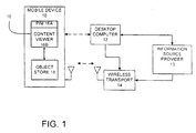
- FIG. 1 is a block diagram of an exemplary portable computing device, herein a mobile device 10 in accordance with the present invention.
- FIG. 1 illustrates that, in one preferred embodiment, the mobile device 10 is suitable for connection with, and to receive information from, a desktop computer 12, a wireless transport 14, or both.
- the wireless transport 14 can be a paging network, cellular digital packet data (CDPD), FM-sideband, or other suitable wireless communications.
- CDPD cellular digital packet data
- FM-sideband FM-sideband
- the mobile device 10 may not be equipped to be connected to the desktop computer 12, and the present invention applies regardless of whether the mobile device 10 is provided with this capability.
- the mobile device 10 preferably includes one or more application programs 16 and an object store 18.
- the application programs 16 can be, for example, a personal information manager (PIM) 16A that stores objects related to a user's electronic mail (e-mail) and scheduling or calendaring information.
- the application programs 16 can also include a content viewer 16B that is used to view information obtained from a wide-area network (WAN), such as the Internet.
- WAN wide-area network
- the content viewer 16B is an "offline" viewer in that information is stored primarily before viewing, wherein the user does not interact with the source of information in real time.
- the present invention can be implemented in a real time environment wherein the wireless transport 14 provides two-way communication.
- the wireless transport 14 is used to send information to the mobile device 10 for storage in the object store 18 and for use by the application programs 16.
- the wireless transport 14 receives the information to be sent from an information source provider 13, which, for example, can be a source of news, weather, sports, traffic or local event information.
- the information source provider 13 can receive e-mail and/or scheduling information from the desktop computer 12 to be transmitted to the mobile device 10 through the wireless transport 14.
- the information from the desktop computer 12 can be supplied to the information source provider 13 through any suitable communication link, such as a direct modem connection.
- the desktop computer 12 and the information source provider 13 can be connected together forming a local area network (LAN) or a wide area network (WAN). Such networking environments are commonplace in offices, enterprise-wide computer network Intranets and the Internet. If desired, the desktop computer 12 can also be directly connected to the wireless transport 14.
- LAN local area network
- WAN wide area network
- the object store 18 is preferably configured to store a plurality of individual records or objects, each comprising a plurality of fields or properties related to features of PIM 16A, or to data viewable on the content viewer 16B.
- object store 18 is configured to store objects, each of which has a plurality of properties which can be associated with e-mail, scheduling or calendaring features provided by PIM 16A.
- the mobile device 10 can be coupled to the desktop computer 12 using any suitable, and commercially available, communication link and using a suitable communications protocol.
- the mobile device 10 communicates with the desktop computer 12 with a physical cable which communicates using a serial communications protocol.
- Other communication mechanisms include infra-red (IR) communication and direct modem communication.
- the mobile device 10 in one embodiment, can be synchronized with the desktop computer 12.
- properties of objects stored in object store 18 are similar to properties of other instances of the same objects stored in the object store 18 on the desktop computer 12 or on the mobile device 14.
- the second instance of that object in the object store 18 of the mobile device 10 is updated the next time the mobile device 10 is connected to the desktop computer 12 so that both instances of the same object contain up-to-date data. This is commonly referred to as synchronization.
- synchronization components run on both the mobile device 10 and the desktop computer 12.
- the synchronization components communicate with one another through well defined interfaces to manage communication and synchronization.
- FIG. 2 is a more detailed block diagram of the mobile device 10.
- the mobile device 10 includes a processor 20, memory 22, input/output (I/O) components 24, a desktop computer communication interface 26 and a wireless receiver 27.
- these components of the mobile device 10 are coupled for communication with one another over a suitable bus 28.
- Memory 22 is preferably implemented as nonvolatile electronic memory such as random access memory (RAM) with a battery back-up module (not shown) such that information stored in memory 22 is not lost when the general power to the mobile device 10 is shut down.
- RAM random access memory
- a portion of memory 22 is preferably allocated as addressable memory for program execution, while the remaining portion of memory 22 is preferably used for storage, such as to simulate storage on a disk drive.
- Memory 22 includes an operating system 30, the application programs 16 (such as PIM 16A discussed with respect to FIG. 1), as well as the object store 18.
- the operating system 30 is preferably loaded into, and executed by, the processor 20 from memory 22.
- the operating system 30, in one preferred embodiment, is a "WINDOWS CE" brand operating system commercially available from Microsoft Corporation.
- the operating system 30 is preferably designed for mobile devices, and implements features which can be utilized by PIM 16A and content viewer 16B through a set of exposed application programming interfaces and methods.
- the objects in object store 18 are preferably maintained by PIM 16A, content viewer 16B and the operating system 30, at least partially in response to calls to the exposed application programming interfaces and methods.
- the I/O components 24, in one preferred embodiment, are provided to facilitate input and output operations from the user of the mobile device 10.
- the I/O components 24 are described in greater detail with respect to FIGS. 3 and 4.
- the desktop computer communication interface 26 is optionally provided as any suitable, and commercially available, communication interface.
- the interface 26 is used to communicate with the desktop computer 12, as described with respect to FIG. 1.
- the wireless receiver 27 receives information from the information source provider 13 and includes an antenna 31.
- the wireless receiver 27 is coupled to the bus 28 for communication with the processor 20 and the object store 18 to store information received from the wireless transport 14 in a manner described below.
- a power supply 35 includes a battery 37 for powering the mobile device 10.
- the power supply 35 communicates with the processor 20 to control power provided to the above-described components.
- One aspect of the present invention is that the power supply 35 provides all power for the mobile device 10, including the wireless receiver 27 without the need for an external battery as typically found in the prior art.
- components of the mobile device 10, such as the I/O components 24, are provided power only when necessary to process the incoming information. This aspect of the present invention is discussed below in greater detail.
- the mobile device 10 can receive power from an external power source 41 that overrides or recharges the built-in battery 37.
- the external power source 41 can include a suitable AC or DC adapter, or a power docking cradle for the mobile device 10.
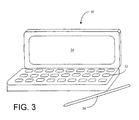
- FIG. 3 is a simplified pictorial illustration of one preferred embodiment of the mobile device 10 which can be used in accordance with the present invention.
- the mobile device 10 can be a desktop assistant sold under the designation H/PC having software provided by the Microsoft Corporation.
- the mobile device 10 includes a miniaturized keyboard 32, a display 34 and a stylus 36.
- the display 34 is a liquid crystal display (LCD) which uses a contact sensitive display screen in conjunction with the stylus 36.
- the stylus 36 is used to press or contact the display 34 at designated coordinates to accomplish certain user input functions.
- the miniaturized keyboard 32 is preferably implemented as a miniaturized alpha-numeric keyboard, with any suitable and desired function keys which are also provided for accomplishing certain user input functions.
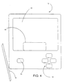
- FIG. 4 is another simplified pictorial illustration of the mobile device 10 in accordance with another preferred embodiment of the present invention.
- the mobile device 10, as illustrated in FIG. 4 includes some items which are similar to those described with respect to FIG. 3, and are similarly numbered.
- the mobile device 10, as shown in FIG. 4 also includes the touch sensitive display 34 which can be used, in conjunction with the stylus 36, to accomplish certain user input functions.
- the display 34 for the mobile device shown in FIGS. 3 and 4 can be the same size, or of sizes, but will typically be much smaller than a conventional display used with a desktop computer.
- the display 34 shown in FIGS. 3 and 4 may be defined by a matrix of only 240x320 coordinates, or 160x160 coordinates, or any other suitable size.
- the mobile device 10 shown in FIG. 4 also includes a number of user input keys or buttons (such as scroll buttons 38) which allow the user to scroll through menu options or other display options which are displayed on display 34, without contacting the display 34.
- the mobile device 10 shown in FIG. 4 also preferably includes a power button 40 which can be used to turn on and off the general power to the mobile device 10.
- the mobile device 10 includes a handwriting area 42.
- Handwriting area 42 can be used in conjunction with the stylus 36 such that the user can write messages which are stored in memory 22 for later use by the mobile device 10.
- the handwritten messages are simply stored in handwritten form and can be recalled by the user and displayed on the display 34 such that the user can review the handwritten messages entered into the mobile device 10.
- the mobile device 10 is provided with a character recognition module such that the user can enter alpha-numeric information into the mobile device 10 by writing that alpha-numeric information on the area 42 with the stylus 36.
- the character recognition module in the mobile device 10 recognizes the alpha-numeric characters and converts the characters into computer recognizable alpha-numeric characters which can be used by the application programs 16 in the mobile device 10.
- FIGS. 3 and 4 Although illustrated in FIGS. 3 and 4 as a handheld portable computer, it should be understood that the present invention can be used in other forms of portable computing devices such as laptops, computers designed for use in automobiles, and portable phones having computers.
- FIG. 5 is a simplified diagram of the wireless receiver 27 as coupled to other components of the mobile device 10.
- information sent by the wireless transport 14 is detected by a RF receiver 60 through the antenna 31.
- the RF receiver 60 provides the wireless information to a processor 62.
- the processor 62 temporarily stores the information in suitable memory, forming, for example, a FIFO (first-in-first-out) buffer.
- the processor 62 and memory 64 are operably coupled to an interface controller 66, which is commonly used to connect components to a computer system.
- the interface controller 66 couples the wireless receiver 27 to the bus 28 and to an interrupt controller 68 that is operably coupled to the processor 20 of the mobile device 10.
- the interface controller 66 is designed and operates according to known industry standards such as PCMCIA and Compact Flash Specifications.
- the components of the wireless receiver 27 form a removable card that can be selectively coupled to an expansion slot provided in the mobile device 10 wherein suitable connectors are provided to couple the interface controller 66 to the bus 28 and the interrupt controller 68 as well as connect the wireless receiver 27 to the power supply 35 illustrated in FIG. 1.
- the interrupt controller 68 is shown as being separate from the processor 20. In other embodiments, the interrupt controller 68 can be designed as part of the processor 20.
- the components of the wireless receiver 27 can be manufactured using known fabrication techniques as implemented in pagers, GSM phones, cellular phones or the like. Although illustrated and discussed below with respect to the processor 62, it should be understood that discrete components can also be used in place of the processor 62.
- Operation of the wireless receiver 27 and the mobile device 10 is directed to efficiently use power from the power supply 35 in order to maximize the operational time between recharging or replacement of the battery 37.
- the wireless receiver 27 is powered and capable of receiving information from the wireless transport 14 at all times irrespective of whether other components of the mobile device 10 are operational and receiving power. This allows the wireless transport 14 to send information to the mobile device 10 even if the user is not interacting with the I/O components 24 of the mobile device 10.
- the processor 20 can have three different modes of operation designed to maximize battery life by minimizing power consumption; full speed, standby and suspend.
- Full speed mode is used to execute applications.
- Standby mode is used during brief idle periods.
- Standby mode can use less than one-tenth (1/10th) of full speed power.
- Suspend mode is used during long idle periods.
- Suspend mode can use less than one-one thousandth (1/1000th) of full speed power.
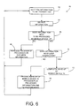
- FIG. 6 illustrates a method of operation 80 of the mobile device 10 and the wireless receiver 27 to process information from the wireless receiver 27.
- the wireless receiver 27 and the mobile device 10 await information to be sent from the wireless transport 14. It is assumed that only the wireless receiver 27 and the interrupt controller 68 are receiving power and operating, while all other components are either off or are in a suspend state, as discussed above.
- step 84 information is received by the RF receiver 60 from the wireless transport 14.
- the information is then processed by the wireless receiver 27 at step 86.
- the processor 62 initially analyzes the information received and determines if the information requires further processing by the processor 20 of the mobile device 10 and/or storage of the information in the object store 18. If at step 86, the processor 62 determines that the processing or storage components of the mobile device 10 are not needed, operational flow continues to step 88 whereat the wireless receiver 27 processes or discards the information received. For instance, upon processing, the processor 62 can determine that the information received does not pertain to the mobile device 10, such as when a wireless address (capcode) does not pertain to the mobile device 10, and thus, the information can be discarded. Alternatively, the processor 62 can determine that all of the information can be temporarily stored in memory 64 for later retrieval by the processor 20 of the mobile device 10. After processing the information at step 88, operational flow returns to step 82 where the wireless receiver 27 awaits further transmitted information.
- Steps 86 and 88 illustrate how the wireless receiver 27 can receive and process information without further interaction with other components of the mobile device 10.
- power consumption from the power supply 35 is conserved since none of the other components of the mobile device 10 have been turned on or operated at a higher power consumption rate.
- step 86 the wireless receiver 27 determines that the information received must be further processed by the mobile device 10.
- step 90 the processor 20 is awoken by the interrupt controller 68 as initiated by the processor 62.
- the processor 20 retrieves the information stored in memory 64 and processes it to determine if user interaction is required. If user interaction is required, operational flow proceeds to step 92 whereat user input devices such as the keyboard 32 are activated and the user is notified of the information through the display 34.
- the processor 20 determines that user interaction is not necessary to process the information, the processor 20 processes the information, turning on only those components of the mobile device 10 that are necessary at step 94. For instance, the information received by the wireless receiver 27 could have exceeded the memory capabilities of memory 64 and that the only required action is to store the information in the object store 18 or other temporary memory provided in the mobile device 10. In such a case, it is not necessary to activate or turn on the keyboard 32 or the display 34.
- the processor 20 merely performs the required actions such as storing the information in memory in the mobile device 10 and returns to the suspend mode. Operational flow then returns to step 82 whereat the wireless receiver awaits further transmitted information.
- Steps 90 and 94 thus illustrate how power consumption is conserved since only a partial wake-up of the mobile device 10 has been performed to process the information. In other words, since only those components necessary to process the information have been turned on, while other components such as the display 34 remain off, power has been conserved and battery life has been extended.
- power can also conserved by monitoring the source of system wake-ups and powering down the system as a function of the source.
- the system can be immediately shutdown upon the completion of processing.
- the system when the system is started by the user using the power button 40, or when the system starts to provide the user a scheduled notification, such as an upcoming appointment, commonly the system will shutdown when a period of non-use has occurred. Rather than waiting for the non-use period to lapse for processing an incoming message, the system will shutdown immediately. However, if the system comes up because of the radio receiver 27 and then the user turns on the system, the system is allowed to remain up and shutdown if the non-use period lapses.
- the source of system start can be monitored by the interrupt controller 68.
- FIG. 7 illustrates a detailed method of operation of the wireless receiver 27 and the mobile device 10.
- the wireless receiver 27 and the mobile device 10 process three types of incoming messages.
- a first type of message is not related to the mobile device 10 and is discarded.
- a second type of message is for the mobile device 10, but either can be received now for further processing at a later time, or can be received and processed at a later time.
- a third type of message is a high priority message that must be processed immediately and may require user interaction. All of these messages are efficiently handled by the method of FIG. 7 to conserve power and maximize battery life.
- wireless data 102 is received by the wireless receiver 27 as indicated at step 104.
- the wireless information is examined by the processor 62 to ascertain if the wireless address of the information pertains to the mobile device 10.
- the wireless receiver 27 will be configured to respond to multiple wireless addresses, wherein each wireless address is used by one or a number of services to send information to the mobile device 10. For instance, one wireless address can be used to send high priority or personal messages to the mobile device 10, while other wireless addresses are used by one or more services to send other information to the mobile device 10.
- the processor 62 ascertains if the wireless information pertains to a valid wireless address of the mobile device 10. If the wireless information does not pertain to the mobile device 10, it is discarded at step 108.
- step 110 valid information for the mobile device 10 is stored in memory 64 of the wireless receiver 27.
- the processor 62 ascertains whether all of the information can be stored in memory 64, or if the mobile device 10 must be at least partially woke up. If the entire incoming information can be stored in memory 64, and the information is not high priority, the processor 62 stores the incoming information at step 112. If, on the other hand, the processor 62 determines that the incoming information cannot be completely stored in memory 64, or that the incoming information pertains to a high priority message, for example, based on its wireless address, an interrupt request is generated at step 114 to wake up the processor 20 of the mobile device 10.
- the size of memory 64 is proportional to the rate at which wireless information is received by the wireless receiver 27 and the amount of time necessary for the processor 20 of the mobile device 10 to wake up and begin extracting information from memory 64.
- the minimum amount of memory is provided in the wireless receiver 27 to store information until the processor 20 wakes up. In this manner, the size of memory 64 present in the wireless receiver 27 is less, thereby reducing the overall size of the wireless receiver 27 and reducing its cost.
- HAL hardware abstraction layer
- CheckAndProcessRadioWakeup() a function herein identified as CheckAndProcessRadioWakeup(). Generally, this function checks if the radio receiver 27 needs some service and whether this service can be handled within HAL or if more components of the device will need to be started.
- the return values include: (1) a first value indicating that the radio receiver 27 has been serviced and there is no need to start other components (herein the first value is "HRADIO_NOCONTINUE”); (2) a second value indicating that the display 34 should be turned on (herein the second value is "HRADIO_CONTINUE_VIDEO_ON”); and (3) a third value indicating that the display 34 should not be turned on (herein the third value is "HRADIO_CONTINUE_VIDEO_OFF"). It should be noted that the return values can be ignored if other wake-up events occur.
- the radio receiver 27 registers information in a data block accessible by the HAL program indicative of the return values. The function is further described in detail in the Appendix along with other functions and related information.
- the processor 20 retrieves the information stored in memory 64 and examines it to determine if the processor can store the information temporarily in a temporary buffer herein called the HAL buffer 120. If temporary storage in the HAL buffer is possible, program flow continues to step 118 whereat the processor 20 executes a device driver buffering routine which stores the information in the HAL buffer 120 as indicated at step 120. The processor 20 then returns to the suspend state as indicated at step 122.
- the processor 20 determines that the information cannot be stored in the HAL buffer 120, for instance, where the information is high priority or of length exceeding the storage available in the HAL buffer 120, the processor 20 continues its wake-up process and a kernel is loaded at step 124.
- Each of the device drivers such as a display driver, a serial port driver, etc., is then loaded at step 126.
- One particular driver that is loaded is a pager driver, which executes a filtering library function is indicated at step 128.
- the pager driver examines the information at step 130 to determine if the information is relevant to the mobile device 10.
- step 130 information is discarded at step 130 if, based on its content, it is not relevant to the mobile device 10. For instance, the user may want to receive only football scores and no other sports scores. However, all of the sports scores may be transmitted with respect to a particular wireless address, thus information on baseball scores would not be discarded at step 106 since this information was transmitted with respect to the correct wireless address for football scores. However, at step 130, the content of the information is examined so baseball scores would be discarded, while football scores are retained. Steps 116 to 128 are very efficient and quick.
- the filtering step 128 examines the initial few bytes of the information and can quickly determine if the information should be kept or discarded.
- the number and location of the bytes to examine are predetermined and agreed upon between the wireless information carrier and software developers.
- the filtering step 128 can execute quickly (the processor 20 is up for less time) and does not require all of the operating system services to be started.
- Non-relevant information is discarded at step 132. It should be noted that upon loading of the pager driver at step 128, any information stored in the HAL buffer 120 at step 120 from prior messages is retrieved and processed.
- the filtering step 128 can include other filtering parameters settable by applications executable on the mobile device 10.
- the filtering library function can include other filtering parameters determined by application programs. For instance, a news viewer application can set a filter parameter where the mobile device 10 always rejects and does not store digital pictures and accepts only the accompanying text.
- the filter parameters can be passed from the application to the filtering library at filtering step 128 using, for example, application program interfaces (APIs). Filtering based on content is described in detail in co-pending application entitled "LOW LEVEL CONTENT FILTERING", filed on even date herewith and incorporated herein by reference.
- step 134 determines if user interaction is needed. For instance, if the message pertains to a high priority message requiring acknowledgement by the user, the mobile device 10 completely wakes up with activation of the display 34 to indicate that a message of high priority has been received. A full wake-up is indicated at step 136.
- high priority messages are ascertained as a function of wireless addresses.
- FIG. 8 is a pictorial representation of a list of wireless addresses 160. Associated with the radio addresses is information as to which addresses are "high priority".
- priority status entries 161 are provided and are settable when an address is for high priority. Any information or message that arrives on an address whose priority status entry 161 has been set will cause a full wake-up of the mobile device 10.
- step 138 if buffer space exists and no further processing is necessary, the processor 20 executes a buffer data routine at step 140 to store the information at step 142. The processor 20 then returns to the suspend state at step 122. If buffer space does not exist at step 138, the mobile device 10 is powered-up without the display 34 at step 144. The information is then processed or additional buffer space is obtained at step 146. If necessary, access and storage can be made in the object store 18. The processor 20 then returns to the suspend state at step 122. It should be noted that considerable power has been conserved since the user input/output (I/O) devices (display 34 and keyboard 32) have not been powered. However, if the user were to activate the mobile device 10 to turn it on, the display 34 would immediately enable.
- I/O input/output
- the mobile device 10 processes incoming wireless messages according to the above-described method in the background whether or not the user is actively interacting with the mobile device 10 using the I/O components 24. It should be noted that if the user were to turn off the mobile device 10, the wireless receiver 27 will remain powered to receive incoming messages. If the user were to turn off the power during processing of an incoming message, the display 34 would turn off to indicate at least partial shut down of the mobile device 10; however, the incoming message would be processed according to the above-described procedure. In this manner, the "power off" signal is trapped and processed when processing of the incoming message is complete (unless the processing of the message results in the need to perform a full wake-up) .
- FIG. 8 is a pictorial representation of a list 160 of wireless addresses. Each wireless address in the list 160 includes an associated operational status entry 163 indicating whether the wireless address is enabled or disabled.
- the list of wireless addresses is static in that the wireless addresses can not be changed by the user.
- the processor 20 of the mobile device 10 can selectively enable or disable each wireless address in the list 160 in memory 64 via the bus 28 and the interface controller 66.
- Selective enabling and disabling of wireless addresses allows the mobile device 10 to further extend battery life by not receiving information that is not of high priority. For instance, the user may subscribe to an information service that provides general sports information that is transmitted with respect to a certain wireless address. This information may be repeatedly transmitted over a given time period such as a number of hours. If the wireless receiver 27 were to continually process the information each time it is transmitted, possibly waking up the mobile device 10 to process the information, the battery 37 (FIG. 1) can be quickly depleted. By selectively enabling or disabling the wireless address in the list 160 pertaining to this information, the wireless receiver 27 can quickly discard the information at step 106 (FIG. 7) in order tc conserve battery power.
- the processor 20 of the mobile device 10 can enable the wireless address pertaining to sports information in list 160 when the mobile device 10 is receiving power from the external power source 41 (FIG. 1). If the mobile device 10 is operating under battery power, the processor 20 can disable the wireless address pertaining to the sports information in order to extend battery life.
- Wireless Services for Windows CE defines a hardware, device drivers, and overall architecture for the incorporation of message-based radio into a Windows CE device. The goal is to create a framework within which applications, system services and hardware all remain modular with respect to each other, thus providing the environment for a wide range of applications.
- Device Windows CE hardware e.g. Palm PC. Auto PC
- Radio Radio HW for a device e.g. a paging card
- OEM Original Equipment Manufacturer e.g. a paging card
- IHV Independent HW Vendor e.g. the radio manufacturer (who develops the HW and/or device driver) HAL Hardware Abstraction Layer. This is implemented by each OEM to abstract their HW implementations from the Windows CE operating system. LCD and VIDEO These two terms have been used interchangeably and refer to the display panel on the device.
- a typical radio device listens to the radio transmissions and determines if there is a message for the user. This determination is based on one or more addresses' that are programmed in the radio receiver or hardware (HW).
- the radio HW is powered independently (i.e., it is powered even when the Windows CE device is powered down) and the radio HW carries out the lowest level of filtering without requiring the Windows CE device to be powered on. This achieves some level of power savings since radio HW. typically require only a fraction of power compared to the Windows CE device.
- Wireless Information Services for Windows CE provides for additional levels of filtering that may or may not be carried out in the radio HW. If the radio HW is separately powered and has enough logic to do additional filtering independent of the device CPU, then it will not cause major power drain from the device power supply. However, it is expected that the majority of the radio HW will be in the Compact Flash card type II form factor (a form factor for most devices) and will not have separate power or CPU due to size constraints. These cards, therefore, will cause a wakeup of the device so that some processing is carried out in the device driver.
- Partial Wakeup state This refers to the device state just after wakeup where HAL has initialized but the kernel and file system are not fully initialized. The objective is to do some processing in this state to filter out unwanted messages and shut down the system as soon as possible, ideally from the partial wakeup state itself.
- radio driver initialization function RIO_Init() is called. In addition to the other initialization, it should call a MS supplied function called RegisterWakeup() and supply the address of a call back function as parameter.
- the call back function (called CheckAndProcessRadioWakeup() in this document) is described below.
- Section 1.1.6.1 describes RegisterWakeup() function that does the following:
- the radio driver is expected to supply a function which will be called during the system wakeup sequence from HAL.
- This function executes in the partial wakeup state and therefore has many limitations and requirements (described later).
- the main purpose of this function is to achieve power savings for the device. Power saving is achieved in many ways as listed below:
- the radio control block data structure is maintained by HAL.
- a pointer to the radio control block is passed to the registered function (called CheckAndProcessRadioWakeup() in this document).
- the radio control block holds pointers to memory blocks that contain data or code. These memory blocks are allocated using VirtualAlloc() function, are locked down so that they are accessible during partial wakeup state, and are accessed using physical addresses.
- the radio control block is an array of RADIO_BLOCK which is defined below:
- the block can be either a pointer to code or a pointer to data as determined by the dwld field.
- the Ids are generated using macros defined in the next section.
- the radio control block stores pointers to code or data that needs to be accessed during partial wakeup state.
- the entries are tagged using an id, which is generated using one of the macros defined below:
- Parl can be either HRADIO_DATA (for defining a data block pointer) or HRADIO_CODE (for defining a function pointer).
- Par2 is an unsigned 16-bit value.
- Par1 can be either HRADIO_DATA (for defining a data block pointer) or HRADIO_CODE (for defining a function pointer).
- Par2 and Par3 have the following meanings: Par2 Par3 0 HRADIO_WAKEUP Pointer to the partial wakeup call back function or data 0 HRADIO_ANALYZE_MSG Pointer to the AnalyzeMessage() function or data 0 HRADIO_FILTER Pointer to the FilterMessage() function or data Address Group Pointer to application filter function or data for the given address/group combination
- This function locates and invokes the AnalyzeMessage() function in partial wakeup state (driver can call the AnalyzeMessage() function directly in other places).
- TRUE Returns TRUE if message had a valid WS header, FALSE otherwise.
- This function locates and invokes the application level filtering mechanism.
- Allocates a memory block locks it down, and creates an entry in the radio control block for it. Then data from the supplied buffer is copied into this newly allocated memory block.
- Null is returned if data block can't be created. pointer to the created radio block is returned otherwise.
- the dwBlockId also indicates whether the block is a code block (function) or data block (buffer).
- This function searches the radio control block for the given block id.
- This function increments or decrements the system busy counter.
- This function turns the video on or off.
- This function is statically part of the radio driver but is called by the HAL during warm boot.
- the main purpose of this function is to check if the radio device needs some service and whether this service can be handled within HAL or it requires the whole system to be woken up.
- This function is called in response to the wakeup interrupt from the radio device (RING_INDICATE interrupt). This function is called by HAL before the kernel is initialized ( partial wakeup state ) . Because of this, this function must meet the following criteria:
- the function should read the data from the radio device and determine if the data needs to be kept or discarded. If the data needs to be kept, it should further determine if it is high priority data (see device driver specifications for discussion of address and group property flags). High priority data needs to be processed immediately and will require a full wakeup. Low priority data may be buffered in memory allocated during startup. If that memory is full, a full wake up is again required to flush that memory. In either case, the data is read off the radio device and appropriate return value is passed to the HAL.
- the skeleton of this function is:
- the device has been serviced, no need to continue the warm boot.
- An example of this case would be when the radio device has a new message that can be buffered in the system memory (done by this function) and no further processing is required.
- the device service needs the system to continue the warm boot with video (the video should be powered on too).
- An example of this case would be when a message is received on a priority address that will cause a notification to be issued.
- the device service needs the system to continue the warm boot without video (the video should not be powered on).
- An example of this case would be when a broadcast message is received when the system memory buffer is full, so processing should continue without video so the system buffer can be flushed.
- ISR interrupt service function
- ISR Partial wakeup call back function Registered using CardRequestIRQ() Registered using RegisterWakeup() Registered for a specified socket and function pair. Registered for a driver. Interrupt condition cleared by Card Services. Call back function needs to clear the interrupt condition. Return as quickly as possible. If more processing needed, spawn a thread and return. Return as quickly as possible, can not spawn a thread. Kernel and file system services available. No kernel or file system services. Always called to handle the interrupt from the radio HW. Called only if the interrupt causes a system wakeup (if the system is already up at the time of the interrupt, only the ISR gets to execute).
- This section defines the types used in the driver API.
- variable length fields are grouped towards the end a length field for each one of them is provided. This allows expanding these structures without losing backward or forward compatibility.
- This struct is used for registering a wakeup function.
- HAL_fVideoState Bool Set if the video is currently powered on, reset otherwise. Set on cold boot. (When the flag is set using HRADIO_CMD_FLAG_SET command, the video is turned ON. When it is reset, the video is turned off).
- HAL_SystemBusy Counter This needs to be implemented as a counter (at least one byte). If non-zero, HAL will trap power off button to prevent system from shutting down.
- HRADIO_CMD_FLAG_SET command increments the counter, HRADIO_FLAG_CLEAR decrements it. Initialized to 0 on cold boot.
- HAL supports IO Control calls to perform operations that are specific to their hardware.
- Most OEMs already implement the following IOCTL call for other services.
- This call registers a radio memory block (RMB) that contains a pointer to the wakeup function that is called during HAL power on processing. If the MemPtr member is NULL then the call does de-registration.
- RMB radio memory block
- the output buffer returns a handle to the RMB (address of the HAL data structure where the device memory block was saved).
- the function supplied must be statically bound to the driver code and small enough to fit within a memory page.
- pBufOut, dwLenOut, and pdwActualOut are used for GET operation only. Set them to NULL for other operations.
- the HAL flags are accessible to the drivers directly (they don't need to make these IOCTL calls).
- This operation locks down the memory pointed to my dwMemPtr.
- the number of pages locked will be determined by the page size and the value ofdwSize.
- the value returned will be the physical address of the first byte pointed to dwMemPtr. This value will normally be adjusted to be not cached and accessible at initial power on.
- This operation unlocks the memory pointed to my dwMemPtr.
- the number of pages unlocked will be determined by the page size and the value of dwSize. This function is used to unlock previously locked memory.
- the LCD initialization code needs to check the wakeup source and determine if the LCD should be turned on or not. If HAL_fVideoRequest flag is implemented, then the processing would be as follows:
- the LCD code also needs to correctly set HAL_fVideoState flag: TRUE when the LCD is powered ON, and FALSE when it is not.
- HAL_fVideoState FALSE
- HAL_fVideoState FALSE
- the OOM (out of memory message) code needs to check HAL_fVideoState and if it is not set (i.e., video is currently not on) then it needs to turn on the video using the HAL IOCTL call. It also needs to clear the HAL_SystemBusy flag.
- OEM_Idle() is called by the Windows CE kernel when there are no more threads or tasks to execute. This function is expected to do a timeout (typically I - 5 minutes) and if no system activity is detected, the system is shutdown.
- this function should check HAL_fVideoState flag. If it is clear (Video is off) then it does not need to do the idle timeout and should shutdown the system immediately.
Abstract
Description
- The present invention relates to personal mobile computing devices commonly known as handheld portable computers. More particularly, the present invention relates to a system and method for receiving wireless information on a mobile device.
- Mobile devices are small electronic computing devices often referred to as personal digital assistants. Many of such mobile devices are handheld devices, or palm-size devices, which comfortably fit within the hand. One commercially available mobile device is sold under the trade name HandHeld PC (or H/PC) having software provided by Microsoft Corporation of Redmond, Washington.
- Generally, the mobile device includes a processor, random access memory (RAM), and an input device such as a keyboard and a display, wherein the keyboard can be integrated with the display, such as a touch sensitive display. A communication interface is optionally provided and is commonly used to communicate with a desktop computer. A replaceable or rechargeable battery powers the mobile device. Optionally, the mobile device can receive power from an external power source that overrides or recharges the built-in battery, such as a suitable AC or DC adapter, or a powered docking cradle.
- In one common application, the mobile device is used in conjunction with the desktop computer. For example, the user of the mobile device may also have access to, and use, a desktop computer at work or at home. The user typically runs the same types of applications on both the desktop computer and on the mobile device. Thus, it is quite advantageous for the mobile device to be designed to be coupled to the desktop computer to exchange information with, and share information with, the mobile device.
- Another technique for providing information to the mobile device is described in the above-identified co-pending U.S. patent applications. Generally, the method and system described therein allow the mobile device to receive information over a wireless, low bit-rate channel or transport, such as a pager network. For example, such information can include electronic mail or news, weather, sports, traffic and local event information typically obtained from a desktop computer connected to the Internet.
- However, the limited battery power available on the mobile device can present significant obstacles in transferring information using the wireless low bit-rate channel. For example, the mobile device should be able to receive information over the wireless transport at any time. However, if the mobile device was merely left on, awaiting information to be received, the battery for the mobile device would be quickly depleted. This method of operation would require the user to constantly recharge or replace the battery.
- Alternatively, a wireless receiver on the mobile device can turn on the mobile device when it detects that information is being sent to the mobile device. However, if large amounts of information are being transmitted over the wireless transport, the wireless receiver can turn on the mobile device so often that again the battery for the mobile device can Be quickly depleted.
- Another drawback of most wireless receivers for a mobile device is that the wireless receiver requires its own battery, separate from the battery used on the mobile device since the mobile device can be turned off at any time. This increases the size, weight and cost of the wireless receiver as well as complicates use for the user since he must maintain both batteries.
- There is a continuing need to improve wireless communication with a mobile device. In particular, there is a need to efficiently process information transmitted over a wireless channel to the mobile device in order to conserve battery resources on the mobile device.
- An article by G. Oliverio entitled "A Paging HPC" published in the July/August 1997 issue of Handheld Systems by Creative Digital Publishing Inc. proposes combining a conventional paging receiver, a FLEX chipset and a portable computer to enable the portable computer to receive data over a wireless paging network. The FLEX chipset wakes the PDA processor whenever an incoming message is received and stored in the FLEX SPI buffer.
-
EP 0 434 231 A2 also discloses a paging receiver in combination with a portable computer. Again, the PDA processor is awoken whenever a message is received by the paging receiver.WO 90/13213 - The invention provides a method for receiving wireless information on a portable computing device as set out in
Claim 1, and a corresponding combination of a wireless receiver and a portable computing device as set out in claim 17. - In embodiments of the invention a wireless receiver is powered only from a battery of the portable computing device. Wireless information is received and stored in memory of the wireless receiver. The wireless receiver wakes up a processor of the portable computing device when the wireless information fills a threshold of the memory available in the wireless receiver. The wireless information is then transferred from the memory of the wireless receiver to the memory of the portable computing device.
- The wireless receiver includes a radio receiver for receiving wireless information, memory for storing the wireless information and a processor for analyzing the wireless information. The radio receiver, the memory and the processor are powered only from the portable computing device.
- Embodiments of the present invention also include a method for receiving wireless information on a portable computing device, wherein the wireless information is transmitted to the portable computing device with respect to wireless addresses. The method includes providing a list of wireless addresses on the portable computing device. Each wireless address corresponds to selected information to be received. Each wireless address also includes an associated status entry indicating enablement of the wireless address. The method further includes selectively enabling and disabling the status entry for the wireless address to allow receipt of the corresponding information as a function of an operating parameter of the device. In one exemplary embodiment, the operating parameter indicates when the portable computing device is being powered or connected to an external source such as a power docking cradle.
-
- FIG. 1 is a simplified block diagram illustrating one embodiment of a mobile device in accordance with the present invention.
- FIG. 2 is a more detailed block diagram of one embodiment of the mobile device shown in FIG. 1.
- FIG. 3 is a simplified pictorial illustration of one embodiment of the mobile device in accordance with the present invention.
- FIG. 4 is a simplified pictorial illustration of another embodiment of the mobile device in accordance with the present invention.
- FIG. 5 is a simplified schematic illustration of a wireless receiver in accordance with the present invention.
- FIG. 6 is a flow chart illustrating a method of operation for the wireless receiver and the mobile device.
- FIG. 7 illustrates a detailed flow chart illustrating operation of the wireless receiver and the mobile device.
- FIG. 8 is a pictorial representation of a list of wireless addresses.
- FIG. 1 is a block diagram of an exemplary portable computing device, herein a
mobile device 10 in accordance with the present invention. FIG. 1 illustrates that, in one preferred embodiment, themobile device 10 is suitable for connection with, and to receive information from, adesktop computer 12, awireless transport 14, or both. Thewireless transport 14 can be a paging network, cellular digital packet data (CDPD), FM-sideband, or other suitable wireless communications. However, it should also be noted that themobile device 10 may not be equipped to be connected to thedesktop computer 12, and the present invention applies regardless of whether themobile device 10 is provided with this capability. - In any case, the
mobile device 10 preferably includes one ormore application programs 16 and anobject store 18. Theapplication programs 16 can be, for example, a personal information manager (PIM) 16A that stores objects related to a user's electronic mail (e-mail) and scheduling or calendaring information. Theapplication programs 16 can also include acontent viewer 16B that is used to view information obtained from a wide-area network (WAN), such as the Internet. In one embodiment, thecontent viewer 16B is an "offline" viewer in that information is stored primarily before viewing, wherein the user does not interact with the source of information in real time. However, it should be understood that the present invention can be implemented in a real time environment wherein thewireless transport 14 provides two-way communication. - The
wireless transport 14 is used to send information to themobile device 10 for storage in theobject store 18 and for use by theapplication programs 16. Thewireless transport 14 receives the information to be sent from aninformation source provider 13, which, for example, can be a source of news, weather, sports, traffic or local event information. Likewise, theinformation source provider 13 can receive e-mail and/or scheduling information from thedesktop computer 12 to be transmitted to themobile device 10 through thewireless transport 14. The information from thedesktop computer 12 can be supplied to theinformation source provider 13 through any suitable communication link, such as a direct modem connection. In another embodiment, thedesktop computer 12 and theinformation source provider 13 can be connected together forming a local area network (LAN) or a wide area network (WAN). Such networking environments are commonplace in offices, enterprise-wide computer network Intranets and the Internet. If desired, thedesktop computer 12 can also be directly connected to thewireless transport 14. - The
object store 18 is preferably configured to store a plurality of individual records or objects, each comprising a plurality of fields or properties related to features ofPIM 16A, or to data viewable on thecontent viewer 16B. For example, wherePIM 16A is an e-mail and scheduling program,object store 18 is configured to store objects, each of which has a plurality of properties which can be associated with e-mail, scheduling or calendaring features provided byPIM 16A. - It is also worth noting that, in one embodiment, the
mobile device 10 can be coupled to thedesktop computer 12 using any suitable, and commercially available, communication link and using a suitable communications protocol. For instance, in one embodiment, themobile device 10 communicates with thedesktop computer 12 with a physical cable which communicates using a serial communications protocol. Other communication mechanisms include infra-red (IR) communication and direct modem communication. - It is also worth noting that the
mobile device 10, in one embodiment, can be synchronized with thedesktop computer 12. In that instance, properties of objects stored inobject store 18 are similar to properties of other instances of the same objects stored in theobject store 18 on thedesktop computer 12 or on themobile device 14. Thus, for example, when one instance of an object stored in theobject store 18 on thedesktop computer 12, the second instance of that object in theobject store 18 of themobile device 10 is updated the next time themobile device 10 is connected to thedesktop computer 12 so that both instances of the same object contain up-to-date data. This is commonly referred to as synchronization. - In order to accomplish synchronization, synchronization components run on both the
mobile device 10 and thedesktop computer 12. The synchronization components communicate with one another through well defined interfaces to manage communication and synchronization. - FIG. 2 is a more detailed block diagram of the
mobile device 10. Themobile device 10 includes aprocessor 20,memory 22, input/output (I/O)components 24, a desktopcomputer communication interface 26 and awireless receiver 27. In a preferred embodiment, these components of themobile device 10 are coupled for communication with one another over asuitable bus 28. -
Memory 22 is preferably implemented as nonvolatile electronic memory such as random access memory (RAM) with a battery back-up module (not shown) such that information stored inmemory 22 is not lost when the general power to themobile device 10 is shut down. A portion ofmemory 22 is preferably allocated as addressable memory for program execution, while the remaining portion ofmemory 22 is preferably used for storage, such as to simulate storage on a disk drive. -
Memory 22 includes anoperating system 30, the application programs 16 (such asPIM 16A discussed with respect to FIG. 1), as well as theobject store 18. During operation, theoperating system 30 is preferably loaded into, and executed by, theprocessor 20 frommemory 22. Theoperating system 30, in one preferred embodiment, is a "WINDOWS CE" brand operating system commercially available from Microsoft Corporation. Theoperating system 30 is preferably designed for mobile devices, and implements features which can be utilized byPIM 16A andcontent viewer 16B through a set of exposed application programming interfaces and methods. The objects inobject store 18 are preferably maintained byPIM 16A,content viewer 16B and theoperating system 30, at least partially in response to calls to the exposed application programming interfaces and methods. - The I/
O components 24, in one preferred embodiment, are provided to facilitate input and output operations from the user of themobile device 10. The I/O components 24 are described in greater detail with respect to FIGS. 3 and 4. - The desktop
computer communication interface 26 is optionally provided as any suitable, and commercially available, communication interface. Theinterface 26 is used to communicate with thedesktop computer 12, as described with respect to FIG. 1. - The
wireless receiver 27 receives information from theinformation source provider 13 and includes anantenna 31. Thewireless receiver 27 is coupled to thebus 28 for communication with theprocessor 20 and theobject store 18 to store information received from thewireless transport 14 in a manner described below. - A
power supply 35 includes abattery 37 for powering themobile device 10. Thepower supply 35 communicates with theprocessor 20 to control power provided to the above-described components. One aspect of the present invention is that thepower supply 35 provides all power for themobile device 10, including thewireless receiver 27 without the need for an external battery as typically found in the prior art. In a second aspect of the present invention, components of themobile device 10, such as the I/O components 24, are provided power only when necessary to process the incoming information. This aspect of the present invention is discussed below in greater detail. - Optionally, the
mobile device 10 can receive power from anexternal power source 41 that overrides or recharges the built-inbattery 37. For instance, theexternal power source 41 can include a suitable AC or DC adapter, or a power docking cradle for themobile device 10. - FIG. 3 is a simplified pictorial illustration of one preferred embodiment of the
mobile device 10 which can be used in accordance with the present invention. Themobile device 10, as illustrated in FIG. 3, can be a desktop assistant sold under the designation H/PC having software provided by the Microsoft Corporation. In one preferred embodiment, themobile device 10 includes aminiaturized keyboard 32, adisplay 34 and astylus 36. In the embodiment shown in FIG. 3, thedisplay 34 is a liquid crystal display (LCD) which uses a contact sensitive display screen in conjunction with thestylus 36. Thestylus 36 is used to press or contact thedisplay 34 at designated coordinates to accomplish certain user input functions. Theminiaturized keyboard 32 is preferably implemented as a miniaturized alpha-numeric keyboard, with any suitable and desired function keys which are also provided for accomplishing certain user input functions. - FIG. 4 is another simplified pictorial illustration of the
mobile device 10 in accordance with another preferred embodiment of the present invention. Themobile device 10, as illustrated in FIG. 4, includes some items which are similar to those described with respect to FIG. 3, and are similarly numbered. For instance, themobile device 10, as shown in FIG. 4, also includes the touchsensitive display 34 which can be used, in conjunction with thestylus 36, to accomplish certain user input functions. It should be noted that thedisplay 34 for the mobile device shown in FIGS. 3 and 4 can be the same size, or of sizes, but will typically be much smaller than a conventional display used with a desktop computer. For example, thedisplay 34 shown in FIGS. 3 and 4 may be defined by a matrix of only 240x320 coordinates, or 160x160 coordinates, or any other suitable size. - The
mobile device 10 shown in FIG. 4 also includes a number of user input keys or buttons (such as scroll buttons 38) which allow the user to scroll through menu options or other display options which are displayed ondisplay 34, without contacting thedisplay 34. In addition, themobile device 10 shown in FIG. 4 also preferably includes apower button 40 which can be used to turn on and off the general power to themobile device 10. - It should also be noted that in the embodiment illustrated in FIG. 4, the
mobile device 10 includes ahandwriting area 42.Handwriting area 42 can be used in conjunction with thestylus 36 such that the user can write messages which are stored inmemory 22 for later use by themobile device 10. In one preferred embodiment, the handwritten messages are simply stored in handwritten form and can be recalled by the user and displayed on thedisplay 34 such that the user can review the handwritten messages entered into themobile device 10. In another preferred embodiment, themobile device 10 is provided with a character recognition module such that the user can enter alpha-numeric information into themobile device 10 by writing that alpha-numeric information on thearea 42 with thestylus 36. In that instance, the character recognition module in themobile device 10 recognizes the alpha-numeric characters and converts the characters into computer recognizable alpha-numeric characters which can be used by theapplication programs 16 in themobile device 10. - Although illustrated in FIGS. 3 and 4 as a handheld portable computer, it should be understood that the present invention can be used in other forms of portable computing devices such as laptops, computers designed for use in automobiles, and portable phones having computers.
- FIG. 5 is a simplified diagram of the
wireless receiver 27 as coupled to other components of themobile device 10. Generally, information sent by thewireless transport 14 is detected by aRF receiver 60 through theantenna 31. TheRF receiver 60 provides the wireless information to aprocessor 62. Theprocessor 62 temporarily stores the information in suitable memory, forming, for example, a FIFO (first-in-first-out) buffer. Theprocessor 62 andmemory 64 are operably coupled to aninterface controller 66, which is commonly used to connect components to a computer system. In particular, theinterface controller 66 couples thewireless receiver 27 to thebus 28 and to an interrupt controller 68 that is operably coupled to theprocessor 20 of themobile device 10. Theinterface controller 66 is designed and operates according to known industry standards such as PCMCIA and Compact Flash Specifications. In one embodiment, the components of thewireless receiver 27 form a removable card that can be selectively coupled to an expansion slot provided in themobile device 10 wherein suitable connectors are provided to couple theinterface controller 66 to thebus 28 and the interrupt controller 68 as well as connect thewireless receiver 27 to thepower supply 35 illustrated in FIG. 1. In the embodiment illustrated, the interrupt controller 68 is shown as being separate from theprocessor 20. In other embodiments, the interrupt controller 68 can be designed as part of theprocessor 20. The components of thewireless receiver 27 can be manufactured using known fabrication techniques as implemented in pagers, GSM phones, cellular phones or the like. Although illustrated and discussed below with respect to theprocessor 62, it should be understood that discrete components can also be used in place of theprocessor 62. - Operation of the
wireless receiver 27 and themobile device 10 is directed to efficiently use power from thepower supply 35 in order to maximize the operational time between recharging or replacement of thebattery 37. In one preferred embodiment, thewireless receiver 27 is powered and capable of receiving information from thewireless transport 14 at all times irrespective of whether other components of themobile device 10 are operational and receiving power. This allows thewireless transport 14 to send information to themobile device 10 even if the user is not interacting with the I/O components 24 of themobile device 10. - When it is desired that the
mobile device 10 receive information at all times, power from thepower supply 35 is principally provided to the interrupt controller 68 and thewireless receiver 27, while all other components of themobile device 10 do not receive power, or receive only enough power to operate in a "suspend" mode or state. For instance, theprocessor 20 can have three different modes of operation designed to maximize battery life by minimizing power consumption; full speed, standby and suspend. Full speed mode is used to execute applications. Standby mode is used during brief idle periods. Standby mode can use less than one-tenth (1/10th) of full speed power. Suspend mode is used during long idle periods. Suspend mode can use less than one-one thousandth (1/1000th) of full speed power. - FIG. 6 illustrates a method of
operation 80 of themobile device 10 and thewireless receiver 27 to process information from thewireless receiver 27. Atstep 82, thewireless receiver 27 and themobile device 10 await information to be sent from thewireless transport 14. It is assumed that only thewireless receiver 27 and the interrupt controller 68 are receiving power and operating, while all other components are either off or are in a suspend state, as discussed above. - At
step 84, information is received by theRF receiver 60 from thewireless transport 14. The information is then processed by thewireless receiver 27 atstep 86. In the embodiment illustrated, theprocessor 62 initially analyzes the information received and determines if the information requires further processing by theprocessor 20 of themobile device 10 and/or storage of the information in theobject store 18. If atstep 86, theprocessor 62 determines that the processing or storage components of themobile device 10 are not needed, operational flow continues to step 88 whereat thewireless receiver 27 processes or discards the information received. For instance, upon processing, theprocessor 62 can determine that the information received does not pertain to themobile device 10, such as when a wireless address (capcode) does not pertain to themobile device 10, and thus, the information can be discarded. Alternatively, theprocessor 62 can determine that all of the information can be temporarily stored inmemory 64 for later retrieval by theprocessor 20 of themobile device 10. After processing the information atstep 88, operational flow returns to step 82 where thewireless receiver 27 awaits further transmitted information. -
Steps wireless receiver 27 can receive and process information without further interaction with other components of themobile device 10. Thus, power consumption from thepower supply 35 is conserved since none of the other components of themobile device 10 have been turned on or operated at a higher power consumption rate. - If at
step 86, thewireless receiver 27 determines that the information received must be further processed by themobile device 10, operational flow continues to step 90. Atstep 90, theprocessor 20 is awoken by the interrupt controller 68 as initiated by theprocessor 62. Theprocessor 20 retrieves the information stored inmemory 64 and processes it to determine if user interaction is required. If user interaction is required, operational flow proceeds to step 92 whereat user input devices such as thekeyboard 32 are activated and the user is notified of the information through thedisplay 34. - If at
step 90, theprocessor 20 determines that user interaction is not necessary to process the information, theprocessor 20 processes the information, turning on only those components of themobile device 10 that are necessary atstep 94. For instance, the information received by thewireless receiver 27 could have exceeded the memory capabilities ofmemory 64 and that the only required action is to store the information in theobject store 18 or other temporary memory provided in themobile device 10. In such a case, it is not necessary to activate or turn on thekeyboard 32 or thedisplay 34. Theprocessor 20 merely performs the required actions such as storing the information in memory in themobile device 10 and returns to the suspend mode. Operational flow then returns to step 82 whereat the wireless receiver awaits further transmitted information. -
Steps mobile device 10 has been performed to process the information. In other words, since only those components necessary to process the information have been turned on, while other components such as thedisplay 34 remain off, power has been conserved and battery life has been extended. - At this point, it should also be noted that power can also conserved by monitoring the source of system wake-ups and powering down the system as a function of the source. In particular, if the system is started in order to process an incoming message from the
radio receiver 27, the system can be immediately shutdown upon the completion of processing. In contrast, when the system is started by the user using thepower button 40, or when the system starts to provide the user a scheduled notification, such as an upcoming appointment, commonly the system will shutdown when a period of non-use has occurred. Rather than waiting for the non-use period to lapse for processing an incoming message, the system will shutdown immediately. However, if the system comes up because of theradio receiver 27 and then the user turns on the system, the system is allowed to remain up and shutdown if the non-use period lapses. The source of system start can be monitored by the interrupt controller 68. - FIG. 7 illustrates a detailed method of operation of the
wireless receiver 27 and themobile device 10. Generally, thewireless receiver 27 and themobile device 10 process three types of incoming messages. A first type of message is not related to themobile device 10 and is discarded. A second type of message is for themobile device 10, but either can be received now for further processing at a later time, or can be received and processed at a later time. A third type of message is a high priority message that must be processed immediately and may require user interaction. All of these messages are efficiently handled by the method of FIG. 7 to conserve power and maximize battery life. - In FIG. 7,
wireless data 102 is received by thewireless receiver 27 as indicated atstep 104. Atstep 106, the wireless information is examined by theprocessor 62 to ascertain if the wireless address of the information pertains to themobile device 10. Typically, thewireless receiver 27 will be configured to respond to multiple wireless addresses, wherein each wireless address is used by one or a number of services to send information to themobile device 10. For instance, one wireless address can be used to send high priority or personal messages to themobile device 10, while other wireless addresses are used by one or more services to send other information to themobile device 10. Atstep 106, theprocessor 62 ascertains if the wireless information pertains to a valid wireless address of themobile device 10. If the wireless information does not pertain to themobile device 10, it is discarded atstep 108. - At
step 110, valid information for themobile device 10 is stored inmemory 64 of thewireless receiver 27. At this step, theprocessor 62 ascertains whether all of the information can be stored inmemory 64, or if themobile device 10 must be at least partially woke up. If the entire incoming information can be stored inmemory 64, and the information is not high priority, theprocessor 62 stores the incoming information atstep 112. If, on the other hand, theprocessor 62 determines that the incoming information cannot be completely stored inmemory 64, or that the incoming information pertains to a high priority message, for example, based on its wireless address, an interrupt request is generated atstep 114 to wake up theprocessor 20 of themobile device 10. - At this point, it should be noted that the size of
memory 64 is proportional to the rate at which wireless information is received by thewireless receiver 27 and the amount of time necessary for theprocessor 20 of themobile device 10 to wake up and begin extracting information frommemory 64. In one embodiment, the minimum amount of memory is provided in thewireless receiver 27 to store information until theprocessor 20 wakes up. In this manner, the size ofmemory 64 present in thewireless receiver 27 is less, thereby reducing the overall size of thewireless receiver 27 and reducing its cost. - At
step 116, theprocessor 20 of themobile device 10 executes an initial body of code herein called the hardware abstraction layer (HAL). As part of the HAL wake-up code, HAL can call a function herein identified as CheckAndProcessRadioWakeup(). Generally, this function checks if theradio receiver 27 needs some service and whether this service can be handled within HAL or if more components of the device will need to be started. The return values include: (1) a first value indicating that theradio receiver 27 has been serviced and there is no need to start other components (herein the first value is "HRADIO_NOCONTINUE"); (2) a second value indicating that thedisplay 34 should be turned on (herein the second value is "HRADIO_CONTINUE_VIDEO_ON"); and (3) a third value indicating that thedisplay 34 should not be turned on (herein the third value is "HRADIO_CONTINUE_VIDEO_OFF"). It should be noted that the return values can be ignored if other wake-up events occur. For instance, if the user presses thepower button 40 about the same time as a radio interrupt is also received, and if the return value is "HRADIO_NOCONTINUE" or "HRADIO_CONTINUE_VIDEO_OFF" the return value is ignored. In one embodiment, theradio receiver 27 registers information in a data block accessible by the HAL program indicative of the return values. The function is further described in detail in the Appendix along with other functions and related information. - Based on the return values, the
processor 20 retrieves the information stored inmemory 64 and examines it to determine if the processor can store the information temporarily in a temporary buffer herein called theHAL buffer 120. If temporary storage in the HAL buffer is possible, program flow continues to step 118 whereat theprocessor 20 executes a device driver buffering routine which stores the information in theHAL buffer 120 as indicated atstep 120. Theprocessor 20 then returns to the suspend state as indicated atstep 122. - If, on the other hand, at
step 116, theprocessor 20 determines that the information cannot be stored in theHAL buffer 120, for instance, where the information is high priority or of length exceeding the storage available in theHAL buffer 120, theprocessor 20 continues its wake-up process and a kernel is loaded atstep 124. Each of the device drivers, such as a display driver, a serial port driver, etc., is then loaded atstep 126. One particular driver that is loaded is a pager driver, which executes a filtering library function is indicated atstep 128. The pager driver examines the information atstep 130 to determine if the information is relevant to themobile device 10. In contrast to step 106 where information is discarded if it does not correspond to a wireless address recognized by themobile device 10, information is discarded atstep 130 if, based on its content, it is not relevant to themobile device 10. For instance, the user may want to receive only football scores and no other sports scores. However, all of the sports scores may be transmitted with respect to a particular wireless address, thus information on baseball scores would not be discarded atstep 106 since this information was transmitted with respect to the correct wireless address for football scores. However, atstep 130, the content of the information is examined so baseball scores would be discarded, while football scores are retained.Steps 116 to 128 are very efficient and quick. In particular, thefiltering step 128 examines the initial few bytes of the information and can quickly determine if the information should be kept or discarded. The number and location of the bytes to examine are predetermined and agreed upon between the wireless information carrier and software developers. By examining only the first few bytes, thefiltering step 128 can execute quickly (theprocessor 20 is up for less time) and does not require all of the operating system services to be started. Non-relevant information is discarded atstep 132. It should be noted that upon loading of the pager driver atstep 128, any information stored in theHAL buffer 120 atstep 120 from prior messages is retrieved and processed. - It should be noted that in a further embodiment, the
filtering step 128 can include other filtering parameters settable by applications executable on themobile device 10. In other words, besides filtering on designated bytes within the message, as discussed above, the filtering library function can include other filtering parameters determined by application programs. For instance, a news viewer application can set a filter parameter where themobile device 10 always rejects and does not store digital pictures and accepts only the accompanying text. The filter parameters can be passed from the application to the filtering library at filteringstep 128 using, for example, application program interfaces (APIs). Filtering based on content is described in detail in co-pending application entitled "LOW LEVEL CONTENT FILTERING", filed on even date herewith and incorporated herein by reference. - If the information is relevant to the
mobile device 10 and should not be discarded, program flow continues to step 134 to determine if user interaction is needed. For instance, if the message pertains to a high priority message requiring acknowledgement by the user, themobile device 10 completely wakes up with activation of thedisplay 34 to indicate that a message of high priority has been received. A full wake-up is indicated atstep 136. - In one embodiment, high priority messages are ascertained as a function of wireless addresses. FIG. 8 is a pictorial representation of a list of wireless addresses 160. Associated with the radio addresses is information as to which addresses are "high priority". In the embodiment illustrated,
priority status entries 161 are provided and are settable when an address is for high priority. Any information or message that arrives on an address whosepriority status entry 161 has been set will cause a full wake-up of themobile device 10. - If the information does not require user interaction, program flow continues to step 138. At
step 138, if buffer space exists and no further processing is necessary, theprocessor 20 executes a buffer data routine atstep 140 to store the information atstep 142. Theprocessor 20 then returns to the suspend state atstep 122. If buffer space does not exist atstep 138, themobile device 10 is powered-up without thedisplay 34 atstep 144. The information is then processed or additional buffer space is obtained atstep 146. If necessary, access and storage can be made in theobject store 18. Theprocessor 20 then returns to the suspend state atstep 122. It should be noted that considerable power has been conserved since the user input/output (I/O) devices (display 34 and keyboard 32) have not been powered. However, if the user were to activate themobile device 10 to turn it on, thedisplay 34 would immediately enable. - The
mobile device 10 processes incoming wireless messages according to the above-described method in the background whether or not the user is actively interacting with themobile device 10 using the I/O components 24. It should be noted that if the user were to turn off themobile device 10, thewireless receiver 27 will remain powered to receive incoming messages. If the user were to turn off the power during processing of an incoming message, thedisplay 34 would turn off to indicate at least partial shut down of themobile device 10; however, the incoming message would be processed according to the above-described procedure. In this manner, the "power off" signal is trapped and processed when processing of the incoming message is complete (unless the processing of the message results in the need to perform a full wake-up) . - Another aspect of the present invention allows for selective enabling and disabling of wireless addresses recognized by the
wireless receiver 27. Referring back to step 106 in FIG. 7, the processor 62 (FIG. 5) examines the wireless address of information received and discards information atstep 108 that does not pertain to a wireless address associated with themobile device 10. One aspect of the present invention includes maintaining a list of recognized wireless addresses, for example, inmemory 64, that theprocessor 62 can access when information is received. As stated above, FIG. 8 is a pictorial representation of alist 160 of wireless addresses. Each wireless address in thelist 160 includes an associatedoperational status entry 163 indicating whether the wireless address is enabled or disabled. In a preferred embodiment, the list of wireless addresses is static in that the wireless addresses can not be changed by the user. However, whether the wireless address is enabled or disabled is under the control of the user and/or programming provided in themobile device 10. Referring back to FIG. 5, theprocessor 20 of themobile device 10 can selectively enable or disable each wireless address in thelist 160 inmemory 64 via thebus 28 and theinterface controller 66. - Selective enabling and disabling of wireless addresses allows the
mobile device 10 to further extend battery life by not receiving information that is not of high priority. For instance, the user may subscribe to an information service that provides general sports information that is transmitted with respect to a certain wireless address. This information may be repeatedly transmitted over a given time period such as a number of hours. If thewireless receiver 27 were to continually process the information each time it is transmitted, possibly waking up themobile device 10 to process the information, the battery 37 (FIG. 1) can be quickly depleted. By selectively enabling or disabling the wireless address in thelist 160 pertaining to this information, thewireless receiver 27 can quickly discard the information at step 106 (FIG. 7) in order tc conserve battery power. For instance, theprocessor 20 of themobile device 10 can enable the wireless address pertaining to sports information inlist 160 when themobile device 10 is receiving power from the external power source 41 (FIG. 1). If themobile device 10 is operating under battery power, theprocessor 20 can disable the wireless address pertaining to the sports information in order to extend battery life. - Wireless Services for Windows CE defines a hardware, device drivers, and overall architecture for the incorporation of message-based radio into a Windows CE device. The goal is to create a framework within which applications, system services and hardware all remain modular with respect to each other, thus providing the environment for a wide range of applications.
- This appendix addresses what support the device drivers need to provide to meet the following requirements:
- 1. Power saving achieved by not waking up the whole system.
- 2. Doing background processing without turning on video
-
Device Windows CE hardware (e.g. Palm PC. Auto PC) Radio Radio HW for a device (e.g. a paging card) OEM Original Equipment Manufacturer - In this document this term refers to the device manufacturers IHV Independent HW Vendor - In this document IHV refers to the radio manufacturer (who develops the HW and/or device driver) HAL Hardware Abstraction Layer. This is implemented by each OEM to abstract their HW implementations from the Windows CE operating system. LCD and VIDEO These two terms have been used interchangeably and refer to the display panel on the device. - A typical radio device listens to the radio transmissions and determines if there is a message for the user. This determination is based on one or more addresses' that are programmed in the radio receiver or hardware (HW). The radio HW is powered independently (i.e., it is powered even when the Windows CE device is powered down) and the radio HW carries out the lowest level of filtering without requiring the Windows CE device to be powered on. This achieves some level of power savings since radio HW. typically require only a fraction of power compared to the Windows CE device.
- Wireless Information Services for Windows CE provides for additional levels of filtering that may or may not be carried out in the radio HW. If the radio HW is separately powered and has enough logic to do additional filtering independent of the device CPU, then it will not cause major power drain from the device power supply. However, it is expected that the majority of the radio HW will be in the Compact Flash card type II form factor (a form factor for most devices) and will not have separate power or CPU due to size constraints. These cards, therefore, will cause a wakeup of the device so that some processing is carried out in the device driver.
- Another way to achieve power saving is not to wakeup the system for each message but to buffer them for group processing at a later time. The radio HW may not have enough memory and to use the Windows CE device memory for this purpose will ordinarily require the device to be woken up to run the device driver code that copies message from the radio HW to the system memory. In this case we want the system to be up for a very short duration and there is no need for the display and other subsystems to be powered on. Thus, the power saving goals can be summarized as:
- System comes up quickly and stays powered on for as little time as possible
- The LCD is not turned on until it is needed
- System shuts down as soon as possible (currently, once the system is up, it does a time out of the order of 1-5 minutes to shutdown)
- To achieve the above goals. Win CE Radio device drivers support a state called Partial Wakeup state. This refers to the device state just after wakeup where HAL has initialized but the kernel and file system are not fully initialized. The objective is to do some processing in this state to filter out unwanted messages and shut down the system as soon as possible, ideally from the partial wakeup state itself.
- This section describes what support needs to be provided in the driver.
- During system initialization, radio driver initialization function RIO_Init() is called. In addition to the other initialization, it should call a MS supplied function called RegisterWakeup() and supply the address of a call back function as parameter. The call back function (called CheckAndProcessRadioWakeup() in this document) is described below.
- See section 1.1.8 for sample code for RIO_init() function.
- Section 1.1.6.1 describes RegisterWakeup() function that does the following:
- 1. Calls VirtualAlloc() to allocate needed memory space. This space will be used to store pointers to buffers for radio and other data (e.g. data for filtering functions). This memory is referred to as Radio Control Block.
- 2. Makes the kernel call to lock the driver code and allocated buffers in memory.
- 3. Calls HAL IOCTL calls and registers a function in driver space that will be called by HAL during warm boot when the wakeup source is radio (this function, called CheckAndProcessRadioWakeup() in this document, determines if the wakeup should continue or not). HAL maintains a data structure for each device driver to store this function pointer.
- The radio driver is expected to supply a function which will be called during the system wakeup sequence from HAL. This function executes in the partial wakeup state and therefore has many limitations and requirements (described later). The main purpose of this function is to achieve power savings for the device. Power saving is achieved in many ways as listed below:
- The function could simply read the data off the radio HW and buffer it in the memory blocks for later processing. It could also implement low level filtering (e.g. group level filtering, if the radio HW is not capable of doing it). In this case the function returns a value indicating that system wakeup is not required (in this scenario this function acts like an interrupt service routine, quickly servicing the radio HW and shutting down the system as soon as possible)
- If the system buffers are full, the function could return a value indicating to the HAL that a system wakeup is required but there is no need to power the display. In this scenario, the system will wakeup and execute message router and other components that process the messages and most likely will shut down the system after processing is complete.
- If the data is high priority (e.g. a personal page), the function should return a value indicating to the HAL that a full system wakeup is required because this message will most likely cause a user notification.
- The radio control block data structure is maintained by HAL. A pointer to the radio control block is passed to the registered function (called CheckAndProcessRadioWakeup() in this document). The radio control block holds pointers to memory blocks that contain data or code. These memory blocks are allocated using VirtualAlloc() function, are locked down so that they are accessible during partial wakeup state, and are accessed using physical addresses.
- The radio control block is an array of RADIO_BLOCK which is defined below:
      typedef struct _hradio_block {
            DWORD dwId; // Block ID
            DWORD PAddr; // Physical address of
                   block
            DWORD VAddr; // Virtual address of
                   block
            DWORD dwSize; // Size of block
      } HRADIO_BLOCK, *LPHRADIO_BLOCK;
| Par2 | Par3 | |
| 0 | HRADIO_WAKEUP | Pointer to the partial wakeup call back function or data |
| 0 | HRADIO_ANALYZE_MSG | Pointer to the AnalyzeMessage() function or data |
| 0 | HRADIO_FILTER | Pointer to the FilterMessage() function or data |
| Address | Group | Pointer to application filter function or data for the given address/group combination |
- Creates the Radio control block (VirtualAlloc(), lock it, register with the HAL)
- Makes HAL IOCTL call to register the wakeup callback function (which will be called by HAL during partial wakeup sequence)
- Makes HAL IOCTL call to register AnalyzeMessage() function (which deciphers the message header)
- Makes HAL IOCTL call to register FilterMessage() function (which invokes the application level filtering functions)
- DeviceId
- Identifies the device controlled by this driver (this parameter is derived from the parameter passed to the RIO_Init() function)
- NumBlocks
- Number of additional radio control block entries needed by the driver (driver will need one entry for each buffer or function it intends to use during partial wakeup state). This does not include system required entries, e.g. the partial wakeup callback function etc.
- pWakeupFn
- Pointer to the partial wakeup callback function.
- dwWakeupFnSize
- Size in bytes of the partial wakeup callback function. If not used, pass a 0 value.
- pMsg
- Pointer to the message bytes.
- dwMsgLen
- Length of the message.
- pfDiscard
- Receives a BOOL value indicating whether the message should be discarded or kept.
- pGroupCode
- Receives the Group code.
- pMsg
- Pointer to the message bytes.
- dwMsgLen
- Length of the message.
- Address
- Address number this message came on.
- GroupCode
- Group code this message came on.
- DeviceId
- The block will be added to the radio control block for this device.
- dwBlockId
- Block ld to be assigned (This id must be output of macros defined in 1.1.5.2)
- IpbData
- Pointer to the data that will be copied in a newly allocated memory block.
- dwDataLen
- Length of the data (this is the size of the newly allocated memory block)
- DeviceId
- The block will be searched in the radio control block for this device.
- dwBlockId
- Block Id to be assigned (This id must be output of macros defined in 1.1.5.2)
- State
- If TRUE, increments the busy counter. FALSE decrements busy counter.
- State
- If TRUE, turns video on. FALSE turns video off.
         DWORD Check And Process Radio Wakeup (
           DWORD MemPtr Pointer to radio control block
           )
- The function must be on a page boundary.
- The function will be executed in physical mode
- The function must not call any OS or file system calls.
- The function must not call any other function. (If it needs to call other driver supplied functions, they must be called via a function pointer table initialized during startup. See Error! Reference source not found. and Error! Reference source not found. for details.)
- read data off the radio HW
- Call AnalyzeMessage() to get the group code information from the message header
- Do group level filtering (if the HW has not done it)
- Invoke application level filtering mechanism. Do message filtering based on the return code.
- if message is to be kept, then buffer it and return appropriate return code
- LocateAndCallAnalyzeMessage() - this function invokes the AnalyzeMessage() function described in the device driver specifications.
- LocateAndCallFilterMessage() - this function invokes application level filtering (to be documented).
| ISR | Partial wakeup call back function |
| Registered using CardRequestIRQ() | Registered using RegisterWakeup() |
| Registered for a specified socket and function pair. | Registered for a driver. |
| Interrupt condition cleared by Card Services. | Call back function needs to clear the interrupt |
| condition. | |
| Return as quickly as possible. If more processing needed, spawn a thread and return. | Return as quickly as possible, can not spawn a thread. |
| Kernel and file system services available. | No kernel or file system services. |
| Always called to handle the interrupt from the radio HW. | Called only if the interrupt causes a system wakeup (if the system is already up at the time of the interrupt, only the ISR gets to execute). |
| Responsible to copy the message from the radio HW, to analyze it, and to filter it. Can call the MS supplied functions directly to do these. | Responsible to copy the message from the radio HW, to analyze it, and to filter it. Can call the MS supplied functions using special indirection methods only. |
| Is a normal user-mode function. | Is a special function that executes in physical mode and has special restriction on it (e.g., must be on a page boundary, can not call other functions, etc.) |
 HINSTANCE HalLib;
 LPHRADIO_BLOCK HalMem;

 // Since the Register function needs to be located on
 // a page boundary, the following pragma assures that.
 DWORD CheckAndProcessRadioWakeup(DWORD);
 #pragma alloc_text (".wakeup)", CheckAndProcessRadioakeup;

 ...
 HalLib = LoadDriver(TEXT("riohal.dll"));
 if (HalLib) {
   func = GetProcAddress(pRadioCtl->HalLib,
                   TEXT("RegisterWakeup"));
   if (func) {
             // Call RegisterWakeup()
             HalMem = (LPHRADIO_BLOCK)
                   (*func) ((DWORD) CheckAndProcessRadioWakeup);
     }
 }
 LPBYTE pAddressTag, pGroupTag;
 BOOL fDiscard, fGroupFound;
 BYTE GroupCode;
 char *p, buf[1000];
 BYTE bMsgBuf[MAX_MSG_SIZE];
 WORD dwMsgSize;
 char address = 1;

 // Fill szMsaBuf[] with message data from the Radio HW
 // do group filterning
 fGroupFound = LocateAndCallAnalyzeMessage(bMsgBuf, dwMsgSize,
                                 &fDiscard, &GroupCode);
 if (fGroupFound) {
      if (fDiscard) [
             // discard message
             return HRADIO_NOCONTINUE;
      }
      // Search driver data structure for group info relating
      to
      // the address this message came on and the group code
      // (returned by the AnalyzeMessage() above
      // if GroupCode is not found or it is disabled then
      // also discard the message
      if (!LocateAndCall FilterMessage(bMsgBuf, dwMsgSize,
                          Address, GroupCode))
      {
             // discard message
             return HRADIO _NOCONTINUE;
       }
       // here buffer the message and return HRADIO_NOCONTINUER
       // if buffer full then return HRADIO_CONTINUE_VIDEO_OFF
 } else {
       // treat as a normal page message (cause full wakeup,
       etc.)
       ...
       return HRADIO_CONTINUE_VIDEO_OFF;
 }
- BYTE
- Unsigned 8-bit
- WORD
- Signed 16-bit
- DWORD
- Signed 32-bit
- WORD wOperationCode Indicates what operations needs to be performed. This field also determines the rest of the struct.
- WORD wStructSize Each struct has fixed size fields followed by the length of the variable fields. The variable fields follow in the same order as their lengths. The wStructSize field holds the size in bytes of the fixed part of the struct (i.e., fixed fields and the lengths of the variable fields). This field provides a versioning method as well and will be used for backward compatibility in the future releases.
| | Field | |
| 2 | | |
| 2 | | |
| 4 | | |
| 1 | Device |
- WORD wOperationCode
- HAL_IOCTL_CMD_REGISTER_W AKEUP_FUNCTION
- WORD wStructSize
- sizeof (HRADIO_REGISTER)
- DWORD dwMemPtr
- Pointer to a memory block (RMB). The second DWORD of this memory block contains a pointer to the function that will be called by HAL during wakeup to determine if power on sequence should continue or not.
- BYTE Device
- Device number (This is how HAL distinguishes one device's RMB from another).
| | Field | |
| 2 | | |
| 2 | | |
| 2 | wFlag |
- WORD
- wOperationCode One for the following values:
HRADIO_CMD_FLAG_SET
HRADIO_CMD_FLAG_CLEAR
HRADIO_CMD_FLAG_GET - WORD wStructSize
- sizeof(HRADIO_FLAG)
- WORD wFlag
- A code indicating which HAL flags is affected by the requested operation. Values are:
HRADIO_FLAG_VIDEO_STATE
HRADIO_FLAG_SYSTEM_BUSY
| | field | |
| 2 | | |
| 2 | | |
| 4 | | |
| 4 | dwSize |
- WORD
- wOperationCode One for the following values:
HRADIO_CMD_LOCKPAGE
HRADIO_CMD_UNLOCKPAGE. - WORD wStructSize
- sizeof(HRADIO_LOCK)
- DWORD dwMemPtr
- A virtual pointer to memory to be locked or unlocked.
- DWORD dwSize
- The total number of bytes to be locked or unlocked.
| Flag | Type | Meaning |
| HAL_fVideoState | Bool | Set if the video is currently powered on, reset otherwise. Set on cold boot. (When the flag is set using HRADIO_CMD_FLAG_SET command, the video is turned ON. When it is reset, the video is turned off). |
| HAL_SystemBusy | Counter | This needs to be implemented as a counter (at least one byte). If |
| non-zero, HAL will trap power off button to prevent system from shutting down. HRADIO_CMD_FLAG_SET command increments the counter, HRADIO_FLAG_CLEAR decrements it. Initialized to 0 on cold boot. |
DWORD dwCode
PBYTE pBufIn
DWORD dwLenIn
PBYTE pBufOut
DWORD dwLenOut
PDWORD pdwActualOut
);
- dwCode
- Specifies a value indicating the I/O control operation to perform. The code used will be IOCTL-HAL-RADIO-CNTRL.
- pBufln
- Points to the buffer containing data that is input to the HAL.
- dwLenIn
- Specifies the number of bytes of data in the buffer specified for pBufIn.
- pBufOut
- Points to the buffer used to transfer the output data.
- dwLenOut
- Specifies the maximum number of bytes in the buffer specified by pBufOut
- pdwActualOut
- Points to DWORD buffer the function uses to return the actual number of bytes received from the device.


- HAL_OCTL_CMD_SET_FLAG
If the indicated flag is a Boolean flag then set it to TRUE. If it is a counter flag, then increment it. - HAL_IOCTL_CMD_RESET_FLAG
If the indicated flag is a Boolean flag then set it to FALSE. If it is a counter flag and is non-zero, then decrement it. - HAL_IOCTL_CMD_GET_FLAG
Value of the indicated flag is returned in pBufOut. For simplicity, the flag value is always returned as a DWORD (so pBufOut must be large enough to hold at least one DWORD). - Additional processing for HRADIO_FLAG _ VIDEO_STATE:
If the flag changes its state because of a set or a reset command, the video needs to be turned on or off to correctly reflect the new state of this flag. For example, if the HAL_fVideoState is 0 and a HAL_IOCTL_CMD_FLAG_SET is issued on this flag, then the video needs to be turned on. If the flag was already set to 1 (hence the video is already on), then this set command will have no effect and there is no need for any additional processing (the video is already ON).


- 1. When the HAL detects a key, it also needs to check HAL_fVideoState and if it is not set (i.e., video is currently not on) then it needs to turn on the video using the HAL IOCTL call (same code as in touch driver) and eats the key.
- 2. An additional change is required to implement the delayed power off feature. On every power off key press, do the following
       if (HAL_SystemBusy &&
              (KeyPressed == KEY_POWER_OFF)) {
           Turn video off and ignore the key
           //see 1.1.13 for the sample code and
           //comment about HAL_fVideoState
       }
 HRADIO_FLAG CmdBuf;
 CmdBuf.wStructSize = sizoef(HRADIO_FLAG);
 CmdBuf.wOperationCode = HRADIO_CMD_FLAG_SET;
 CmdBuf.wFlag = HRADIO_FLAG_VIDEO_STATE;

 OemIOControl(
       IOCTL_HAL_RADIO_CNTRL, // DWORD dwCode
      &CmdBuf, // PBYTE pBufIn
      sizeof(CmdBuf), // DWORD dwLenIn
      NULL, // PBYTE pBufOut
      0, // DWORD dwLenOut
      &dwWriteBytes // PDWORD pdwActualOut
 );
 CmdBuf.wFlag = HRADIO_FLAG_SYSTEM_BUSY;
 DWORD dwValue;

 while (1) {
      // get the value of SystemBusy counter
      CmdBuf.wOperationCode = HRADIO_CMD_GET:
      if (OemIOControl(
             IOCTL_HAL_RADIO_CNTRL, // DWORD dwCode
             &CmdBuf, // PBYTE pBufIn
             sizeof(CmdBuf), // DWORD dwLenIn
             &dwValue // PBYTE pBufOut
             sizeof (dwValue), // DWORD
 dwLenOut
             &dwWriteBytes // PDWORD
 pdwActualOut
       ) {
             if (dwValue == 0) {
                   break; // we are done
             }

             // decrement SystemBusy counter
             CmdBuf.dwOperationCode = HRADIO_CMD_CLEAR;
             if (!OemIOControl(
                   IOCTL_HAL_RADIO_CNTRL, // DWORD dwCode
                   &CmdBuf, // PBYTE pBufIn
                   sizeof (CmdBuf), // DWORD dwLenIn
                   NULL, // PBYTE pBufOut
                   0, // DWORD
 dwLenOut
                   &dwWriteBytes // PDWORD
 pdwActualOut
             ) {
                   break;
             }
      }
 }
       LPVOID IpOutBuf. DWORD nOutBufSize, LPDWORD
 IpBytesReturned) {
   BOOL retval = FALSE;
   DWORD len;
    DWORD PhysAddr. value;
    PHRADIO_LOCK pHalLock;
    LPHRADIO_ REGISTER pHalReg;
    LPHRADI0_FLAG pHalFlag;

       switch (dwloControlCode) {
         case IOCTL_HAL_RADIO_CNTRL:
           if(nInBufSize < sizeof(WORD)) {
          SetLastError(ERROR_INVALID_PARAMETER);
          break;
        }
        switch (*(LPWORD)IpInBuf) {
          case HRADIO_CMD_LOCKPAGE:
            if (nInBufSize < sizeof(HRADIO_LOCK)) {
              SetLastError(ERROR_INSUFFICIENT_BUFFER);
              break;
            }
            pHalLock = (LPHRADIO_LOCK)lpInBuf;
            if(LockPages((LPVOID)pHalLock->dwMemPtr, 1, &PhysAddr,
 2)){
              memcpy(lpOutBuf, &PhysAddr, sizeof(DWORD));
              retval = TRUE:
            }
            break;

         case HRADIO_CMD_REGISTER:
            if (nInBufSize < sizeof(HRADIO_REGISTER)) {
             SetLastError(ERROR_INSUFFICIENT_BUFFER);
             break;
            }
            pHalReg = (LPHRA DIO_REGISTER)lplnBuf;
            if (pHalReg->Device != 1 && pHaIReg->Device != 2) {
              SetLastError(ERROR_BAD_ DEVICE);
              break;
            }

            if (pHalReg->Device = 1) {
              REG32(OEM_BASE+RADIO1) = UnMapPtr(pHalReg-
 >dwMemPtr);
            } else {
                REG32(OEM_BASE+RADIO2) = UnMapPtr(pHalReg-
 >dwMemPtr);
               }

            if (!pHalReg->dwMemPtr) {
              retval = TRUE;
              break;
            }

            if (nOutBufSize < sizeof(DWORD)) {
             SetLastError(ERROR_INSUFFICIENT_BUFFER);
             break;
            }

            PhysAddr = pHalReg->Device = I? (OEM_BASE+RADIO1):
 (OEM_BASE+RADIO2);
            memcpy(IpOutBuf, &PhysAddr, sizeof(DWORD));
            retval = TRUE;
            break;

          case HRADIO_CMD_FLAG_SET:
            if (nlnBufSize < sizeof(HRADIO_FLAG)) {
              SetLastError_(ERROR_INSUFFICIENT_BUFFER);
              break;
             }
            pHalFlag = (LPHRADIO_FLAG)lplnBuf;
            switch (pHaIFlag->wFlag) {
              case HRADIO_FLAG_VIDEO_STATE:
                 VideoOff();
                 break;

              case HRADIO_FLAG_SYSTEM_BUSY:
                 // need to increment because multiple devices
                 ++REG32(OEM_BASE+RADIO_BUSY);
                 break;
             }
             retval = TRUE;
             break;

          case HRADIO _CMD_ FLAG_ CLEAR:
            if (nInBufSize < sizeof (HRADIO_FLAG)) {
              SetLastError(ERROR_INSUFFICIENT_BUFFER);
              break;
            }
            pHalFlag = (LPHRADIO_FLAG)IplnBuf;
            switch (pHalFlag->wFlag) {
              case HRADIO_FLAG_ VIDEO_STATE:
                VideoOn();
                break;

              case HRADIO_FLAG_SYSTEM_BUSY:
                // need to increment because multiple devices
                if (REG32(OEM_BASE+RADIO_BUSY)) {
                  --REG32(OEM_BASE+RADIO_BUSY);
                }
                break;
            }
            retval = TRUE;
            break;

         case HRADIO_CMD_FLAG_GET:
            if (nInBufSize < sizeof(HRADIO_FLAG)) {
              SetLastError(ERROR_INSUFFICIENT_BUFFER);
              break;
             }
             if (nOutBufSize < sizeof(DWORD)) {
               SetLastError(ERROR INSUFFICIENT_BUFFER);
               break;
             }
             pHalFlag = (LPHRADIO_FLAG)lplnBuf;
             value = 0;
             switch (pHalFlag->wFlag)
             {case HRADIO_FLAG_VIDEO_STATE:
               value = (DWORD)REG8(OEM_BASE+VIDEO_OFF);
               break;
             case HRADIO_FLAG_SYSTEM_BUSY:
               value = REG32(OEM_BASE+RADIO_BUSY);
               break;
             }
             memcpy(IpOutBuf. &value, sizeof(DWORD));
             retval = TRUE;
             break;
           }
           break;
           default:
             SetLastError(ERROR_NOT_SUPPORTED);
             break;
           }
           return retval;
         }
 OEMPowerOn()
       if(WakeupSourceO=CompactFlash_Rl) {
             ret = HRADIO_CONTINUE_VIDEO_ON;
             if(RadioWakeupFunction != NULL) {
               ret = RadioWakeupFunction(HalControlBlock);
             }
             if (ret == HRADIO_CONTINUE_VIDEO_ON) {
                    Videolnit(FALSE);
             } else
             if (ret = HRADIO_CONTINUE_VIDEO_OFF){
                    Vidoelnit(TRUE);
             } else
             GotToSleep();
 Videolnit(BOOL KeepVideoOff);
 VideoOn();
 VideoOffo;
 /* system already running *./
 if ((DWORD)REG8(OEM_BASE+VIDEO_OFF)) {
       if (IsWakeupKey(key)) {
             Video(on);
       }
       IgnoreKey();
 }
 if (IsPowerDownKey(key)) {
       if (REG32(OEM_BASE+RADIO_BUSY)) {
             VideoOff();
             IgnoreKey();
       } else ProcessKey();
 }
 if VideoOff ()
       GoToSleep();
Claims (17)
- A computer implemented method for receiving wireless information on a portable computing device (10), the method comprising:powering a wireless receiver (27) only from a battery (37) of the portable computing device;receiving wireless information;storing the wireless information in memory (64) of the wireless receiver;characterised in that the method further comprises:awaking a processor (20) of the portable computing device when the wireless information fills a threshold of the memory (64) available in the wireless receiver; andtransferring the wireless information from the memory (64) of the wireless receiver to memory (22) of the portable computing device.
- The method of claim 1 and further comprising analyzing the wireless information received from the wireless receiver (27) with the processor (20) of the portable computing device.
- The method of claims 2 and further comprising powering another component of the portable computing device (10) as a function of the wireless information received.
- The method of claim 3 wherein said another component comprises a display (34).
- The method of claims 2 to 4 and further comprising powering a keyboard (32) of the portable computing device as a function of the wireless information analyzed.
- The method of any of claims 2 to 5 wherein the step of analyzing comprises analyzing a content of the wireless information.
- The method of any of claims 2 to 6 wherein the step of analyzing comprises analyzing a wireless address associated with the wireless information.
- The method of claim 7 wherein the wireless address is associated with a priority status entry (161) indicating if priority messages are received thereon, and wherein the method further includes analyzing the priority status entry associated with the wireless information.
- The method of claim 8 and further comprising powering another component of the portable computing device as a function of analyzing the priority status entry (161).
- The method of claim 9 wherein said another component comprises a display (34).
- The method of claim 10 and further comprising powering a keyboard (32) of the portable computing device as a function of analyzing the priority status entry.
- The method of any of claims 8 to 11 and further comprising selectively changing the priority status entry (161) of the wireless address.
- The method of any of claims 2 to 12 wherein the step of analyzing comprises analyzing a selected portion of the wireless information.
- The method of any of claims 2 to 13 wherein the portable computing device (10) includes an executable application (16), and wherein the step of analyzing comprises analyzing the wireless information as a function of information from the executable application.
- The method of any of claims 1 to 14 wherein wireless information is received in accordance with a wireless address, and wherein the wireless address includes an operational status entry (163) indicating if wireless information received thereon should be processed, and wherein storing the wireless information includes storing the wireless information in memory if the operational status entry indicates that the wireless information should be processed.
- The method of claim 15 and further comprising selectively changing the operational status entry of the wireless address.
- A wireless receiver (27) in combination with a portable computing device (10), the combination comprising means adapted to carry out the method steps of any of claims 1 to 16.
Priority Applications (1)
| Application Number | Priority Date | Filing Date | Title |
|---|---|---|---|
| EP07013570A EP1840698B1 (en) | 1998-01-07 | 1999-01-07 | System and method for receiving wireless information on a mobile device |
Applications Claiming Priority (9)
| Application Number | Priority Date | Filing Date | Title |
|---|---|---|---|
| US7072098P | 1998-01-07 | 1998-01-07 | |
| US70720P | 1998-01-07 | ||
| US7512398P | 1998-02-13 | 1998-02-13 | |
| US75123P | 1998-02-13 | ||
| US10772498A | 1998-06-30 | 1998-06-30 | |
| US107724 | 1998-06-30 | ||
| US09/189,024 US6289464B1 (en) | 1998-01-07 | 1998-11-10 | Receiving wireless information on a mobile device with reduced power consumption |
| US189024 | 1998-11-10 | ||
| PCT/US1999/000306 WO1999035557A2 (en) | 1998-01-07 | 1999-01-07 | System and method for receiving wireless information on a mobile device |
Related Child Applications (1)
| Application Number | Title | Priority Date | Filing Date |
|---|---|---|---|
| EP07013570A Division EP1840698B1 (en) | 1998-01-07 | 1999-01-07 | System and method for receiving wireless information on a mobile device |
Publications (2)
| Publication Number | Publication Date |
|---|---|
| EP1058874A1 EP1058874A1 (en) | 2000-12-13 |
| EP1058874B1 true EP1058874B1 (en) | 2007-08-01 |
Family
ID=27490848
Family Applications (1)
| Application Number | Title | Priority Date | Filing Date |
|---|---|---|---|
| EP99904035A Expired - Lifetime EP1058874B1 (en) | 1998-01-07 | 1999-01-07 | System and method for receiving wireless information on a mobile device |
Country Status (4)
| Country | Link |
|---|---|
| EP (1) | EP1058874B1 (en) |
| JP (1) | JP4531974B2 (en) |
| DE (2) | DE69936709T2 (en) |
| WO (1) | WO1999035557A2 (en) |
Families Citing this family (12)
| Publication number | Priority date | Publication date | Assignee | Title |
|---|---|---|---|---|
| US6862347B1 (en) * | 1999-01-28 | 2005-03-01 | Siemens Communications, Inc. | Method and apparatus for extending a telephone's capabilities |
| US6825832B2 (en) | 1999-11-30 | 2004-11-30 | Vercel Development, Inc. | Hand held internet browser with folding keyboard |
| GB0103405D0 (en) | 2001-02-10 | 2001-03-28 | Psion Computers Plc | Power management for combined handheld computer and cellular telephone |
| US20030081579A1 (en) * | 2001-10-29 | 2003-05-01 | Sierra Wireless, Inc., A Canadian Corporation | Apparatus and method for coupling a network data device to a digital network |
| GB2383494B (en) * | 2001-12-19 | 2006-01-25 | Qualcomm | A method of and apparatus for handling messages in a mobile communications environment |
| US8707406B2 (en) * | 2002-07-26 | 2014-04-22 | Sierra Wireless, Inc. | Always-on virtual private network access |
| TW556421B (en) | 2002-08-15 | 2003-10-01 | Htc Corp | Circuit and operating method for integrated interface of PDA and wireless communication system |
| EP1420326A1 (en) * | 2002-11-13 | 2004-05-19 | High Tech Computer Corp. | Circuit and operating method for integrated interface of PDA and wireless communication system |
| US8533272B2 (en) * | 2007-01-30 | 2013-09-10 | Alcatel Lucent | Method and apparatus for notification and delivery of messages to mobile PC users |
| EP2705640B1 (en) * | 2011-06-02 | 2019-02-20 | Huawei Technologies Co., Ltd. | Multiple cpu architecture platform network firewall |
| US9042286B2 (en) * | 2011-11-04 | 2015-05-26 | Intel Corporation | Reducing wireless power consumption and signaling overhead for internet application background messages |
| CN107786712A (en) * | 2016-08-30 | 2018-03-09 | 北京神州泰岳软件股份有限公司 | A kind of compression and storage method and device of contact person in address list information |
Family Cites Families (3)
| Publication number | Priority date | Publication date | Assignee | Title |
|---|---|---|---|---|
| GB8908513D0 (en) * | 1989-04-14 | 1989-06-01 | Blick Communications Ltd | Radio pagers |
| US5043721A (en) * | 1989-12-18 | 1991-08-27 | Hewlett-Packard Company | Paging accessory for portable information/computing devices |
| EP0930593B1 (en) * | 1994-09-27 | 2001-12-19 | Sony Corporation | Paging |
-
1999
- 1999-01-07 JP JP2000527876A patent/JP4531974B2/en not_active Expired - Fee Related
- 1999-01-07 WO PCT/US1999/000306 patent/WO1999035557A2/en active IP Right Grant
- 1999-01-07 DE DE69936709T patent/DE69936709T2/en not_active Expired - Lifetime
- 1999-01-07 EP EP99904035A patent/EP1058874B1/en not_active Expired - Lifetime
- 1999-01-07 DE DE69941233T patent/DE69941233D1/en not_active Expired - Lifetime
Non-Patent Citations (1)
| Title |
|---|
| None * |
Also Published As
| Publication number | Publication date |
|---|---|
| EP1058874A1 (en) | 2000-12-13 |
| DE69936709T2 (en) | 2008-04-30 |
| WO1999035557A2 (en) | 1999-07-15 |
| DE69941233D1 (en) | 2009-09-17 |
| DE69936709D1 (en) | 2007-09-13 |
| JP2002501229A (en) | 2002-01-15 |
| WO1999035557A3 (en) | 1999-09-16 |
| JP4531974B2 (en) | 2010-08-25 |
Similar Documents
| Publication | Publication Date | Title |
|---|---|---|
| US6289464B1 (en) | Receiving wireless information on a mobile device with reduced power consumption | |
| EP1060597B1 (en) | Method and device for content filtering | |
| US6018232A (en) | Method of operating battery powered computing device with radio transmitter | |
| EP1058874B1 (en) | System and method for receiving wireless information on a mobile device | |
| US5974558A (en) | Resume on pen contact | |
| US6126327A (en) | Radio flash update | |
| US6092117A (en) | System and method for automatically reconnecting a wireless interface device to a host computer | |
| US6209034B1 (en) | Remote keyboard macros activated by hot icons | |
| US6360327B1 (en) | System with control registers for managing computer legacy peripheral devices using an advanced configuration power interface software power management system | |
| US6018806A (en) | Method and system for rebooting a computer having corrupted memory using an external jumper | |
| US6137473A (en) | System and method for switching control between a host computer and a remote interface device | |
| US5996082A (en) | System and method for delaying a wake-up signal | |
| US7558884B2 (en) | Processing information received at an auxiliary computing device | |
| EP1996993B1 (en) | Dual mode power-saving computing system | |
| US6782472B2 (en) | Method of initializing a memory controller by executing software in a second memory to wake up a system | |
| US6683605B1 (en) | Screen saver disabler | |
| US8181118B2 (en) | Personal information device on a mobile computing platform | |
| US6141688A (en) | Broadcast search for available host | |
| US5990875A (en) | Double pen up event | |
| US20020103949A1 (en) | Combination personal data assistant and personal computing device with master slave input output | |
| US20040034802A1 (en) | Method and apparatus for a computing system having an active sleep mode CPU that uses the cache of a normal active mode CPU | |
| US20040210699A1 (en) | Method of operating combination personal data assistant and personal computing device | |
| US20040034803A1 (en) | Method and apparatus for a computing system having an active sleep mode | |
| JP2003515765A (en) | Display system | |
| US6005533A (en) | Remote occlusion region |
Legal Events
| Date | Code | Title | Description |
|---|---|---|---|
| PUAI | Public reference made under article 153(3) epc to a published international application that has entered the european phase |
Free format text: ORIGINAL CODE: 0009012 |
|
| 17P | Request for examination filed |
Effective date: 20000804 |
|
| AK | Designated contracting states |
Kind code of ref document: A1 Designated state(s): DE FR GB |
|
| 17Q | First examination report despatched |
Effective date: 20030401 |
|
| GRAP | Despatch of communication of intention to grant a patent |
Free format text: ORIGINAL CODE: EPIDOSNIGR1 |
|
| GRAS | Grant fee paid |
Free format text: ORIGINAL CODE: EPIDOSNIGR3 |
|
| GRAA | (expected) grant |
Free format text: ORIGINAL CODE: 0009210 |
|
| AK | Designated contracting states |
Kind code of ref document: B1 Designated state(s): DE FR GB |
|
| REG | Reference to a national code |
Ref country code: GB Ref legal event code: FG4D |
|
| REF | Corresponds to: |
Ref document number: 69936709 Country of ref document: DE Date of ref document: 20070913 Kind code of ref document: P |
|
| ET | Fr: translation filed | ||
| PLBE | No opposition filed within time limit |
Free format text: ORIGINAL CODE: 0009261 |
|
| STAA | Information on the status of an ep patent application or granted ep patent |
Free format text: STATUS: NO OPPOSITION FILED WITHIN TIME LIMIT |
|
| 26N | No opposition filed |
Effective date: 20080506 |
|
| REG | Reference to a national code |
Ref country code: DE Ref legal event code: R082 Ref document number: 69936709 Country of ref document: DE Representative=s name: PATENTANWAELTE WEICKMANN & WEICKMANN, DE |
|
| REG | Reference to a national code |
Ref country code: GB Ref legal event code: 732E Free format text: REGISTERED BETWEEN 20150115 AND 20150121 |
|
| REG | Reference to a national code |
Ref country code: DE Ref legal event code: R082 Ref document number: 69936709 Country of ref document: DE Representative=s name: WEICKMANN & WEICKMANN PATENT- UND RECHTSANWAEL, DE Effective date: 20150126 Ref country code: DE Ref legal event code: R082 Ref document number: 69936709 Country of ref document: DE Representative=s name: WEICKMANN & WEICKMANN PATENTANWAELTE - RECHTSA, DE Effective date: 20150126 Ref country code: DE Ref legal event code: R082 Ref document number: 69936709 Country of ref document: DE Representative=s name: PATENTANWAELTE WEICKMANN & WEICKMANN, DE Effective date: 20150126 Ref country code: DE Ref legal event code: R081 Ref document number: 69936709 Country of ref document: DE Owner name: MICROSOFT TECHNOLOGY LICENSING, LLC, REDMOND, US Free format text: FORMER OWNER: MICROSOFT CORP., REDMOND, WASH., US Effective date: 20150126 |
|
| REG | Reference to a national code |
Ref country code: FR Ref legal event code: TP Owner name: MICROSOFT TECHNOLOGY LICENSING, LLC, US Effective date: 20150724 |
|
| REG | Reference to a national code |
Ref country code: FR Ref legal event code: PLFP Year of fee payment: 18 |
|
| REG | Reference to a national code |
Ref country code: FR Ref legal event code: PLFP Year of fee payment: 19 |
|
| PGFP | Annual fee paid to national office [announced via postgrant information from national office to epo] |
Ref country code: FR Payment date: 20161215 Year of fee payment: 19 |
|
| PGFP | Annual fee paid to national office [announced via postgrant information from national office to epo] |
Ref country code: DE Payment date: 20170104 Year of fee payment: 19 |
|
| PGFP | Annual fee paid to national office [announced via postgrant information from national office to epo] |
Ref country code: GB Payment date: 20170104 Year of fee payment: 19 |
|
| REG | Reference to a national code |
Ref country code: DE Ref legal event code: R119 Ref document number: 69936709 Country of ref document: DE |
|
| GBPC | Gb: european patent ceased through non-payment of renewal fee |
Effective date: 20180107 |
|
| PG25 | Lapsed in a contracting state [announced via postgrant information from national office to epo] |
Ref country code: FR Free format text: LAPSE BECAUSE OF NON-PAYMENT OF DUE FEES Effective date: 20180131 Ref country code: DE Free format text: LAPSE BECAUSE OF NON-PAYMENT OF DUE FEES Effective date: 20180801 |
|
| REG | Reference to a national code |
Ref country code: FR Ref legal event code: ST Effective date: 20180928 |
|
| PG25 | Lapsed in a contracting state [announced via postgrant information from national office to epo] |
Ref country code: GB Free format text: LAPSE BECAUSE OF NON-PAYMENT OF DUE FEES Effective date: 20180107 |