EP1056293A1 - Method and apparatus for block motion estimation - Google Patents
Method and apparatus for block motion estimation Download PDFInfo
- Publication number
- EP1056293A1 EP1056293A1 EP99110116A EP99110116A EP1056293A1 EP 1056293 A1 EP1056293 A1 EP 1056293A1 EP 99110116 A EP99110116 A EP 99110116A EP 99110116 A EP99110116 A EP 99110116A EP 1056293 A1 EP1056293 A1 EP 1056293A1
- Authority
- EP
- European Patent Office
- Prior art keywords
- search area
- block
- picture elements
- search
- stripes
- Prior art date
- Legal status (The legal status is an assumption and is not a legal conclusion. Google has not performed a legal analysis and makes no representation as to the accuracy of the status listed.)
- Withdrawn
Links
Images


Classifications
-
- H—ELECTRICITY
- H04—ELECTRIC COMMUNICATION TECHNIQUE
- H04N—PICTORIAL COMMUNICATION, e.g. TELEVISION
- H04N19/00—Methods or arrangements for coding, decoding, compressing or decompressing digital video signals
- H04N19/42—Methods or arrangements for coding, decoding, compressing or decompressing digital video signals characterised by implementation details or hardware specially adapted for video compression or decompression, e.g. dedicated software implementation
- H04N19/43—Hardware specially adapted for motion estimation or compensation
- H04N19/433—Hardware specially adapted for motion estimation or compensation characterised by techniques for memory access
-
- H—ELECTRICITY
- H04—ELECTRIC COMMUNICATION TECHNIQUE
- H04N—PICTORIAL COMMUNICATION, e.g. TELEVISION
- H04N19/00—Methods or arrangements for coding, decoding, compressing or decompressing digital video signals
- H04N19/50—Methods or arrangements for coding, decoding, compressing or decompressing digital video signals using predictive coding
- H04N19/503—Methods or arrangements for coding, decoding, compressing or decompressing digital video signals using predictive coding involving temporal prediction
- H04N19/51—Motion estimation or motion compensation
Definitions
- the invention relates to a method and an apparatus for block motion estimation, especially for MPEG2 encoder.
- the current frames are divided spatially into rectangular or square blocks consisting of n x m picture elements (pixels, pels).
- a search for each block of the current frame is performed.
- the picture elements of each block are compared with the picture elements of a block within a search area of a reference frame.
- a cost function i.e. a measure of the match between the compared blocks, is calculated for all search positions.
- the actual motion vector is defined by the relative positions of the two blocks where the cost function has the minimum value.
- the mean of the absolute difference (mad) between current block and candidate block from the reference frame about n x m subtractions, absolute value calculations and additions have to be performed for each search position.
- the invention is based on the object of specifying a method for block motion estimation with reduced implementation requirements e.g. for real-time motion estimation. This object is achieved by means of the method specified in claim 1.
- the above calculated computational demand can be fulfilled for real-time motion estimation only by massive parallel processing of the cost function. If a parallel search on several independent search areas is performed, the required communication bandwidth between the memories storing the search areas and the arithmetic unit performing the cost function calculation would grow linear with the number of parallel processed searches. However, this is not true, if neighbouring blocks of the current frame are fed to several processing elements, wherein the processing elements perform the search for these blocks on a common search area.
- the method for block motion estimation consists in the fact that
- the lines of the current frame are separated into block sections comprising k neighbouring blocks which are processed in parallel, wherein the horizontal width of the block sections is equal to the horizontal width of the search area.
- search area stripes have a vertical width equal to the vertical width of the search area.
- the picture elements of the search area stripes are compared in parallel (Fig. 4) with the picture elements of the k neighbouring blocks.
- the picture elements of the search area stripes are compared in serial (Fig. 3) with the picture elements of the k neighbouring blocks.
- the block motion estimation is part of an MPEG encoding of video signals and the blocks are macroblocks with a horizontal and vertical macroblock size of 16 picture elements.
- the apparatus for image motion estimation includes:
- the apparatus further comprises:
- processing elements are arranged in serial order.
- processing elements are arranged in parallel order.
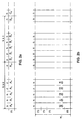
- Figure 1a illustrates the division of a current frame into h x v macroblocks MB 0 , MB 1 , MB h-1 , etc. with a horizontal macroblock size of n picture elements and a vertical macroblock size of m picture elements.
- a search area is assigned to each of the macroblocks. For an example of three neighboring macroblocks MB r , MB s , MB t the respective search areas overlap as shown in figure 1b).
- a first part S r of the search area of macroblock MB r is only used for macroblock MB r , a second part S rs is also used for macroblock MB s and finally a third part S rst is used for macroblocks MB r , MB s , MB t .
- the search area for macroblock MB s comprises besides the already mentioned parts S rs and S rst a further part S st which is also used for the macroblock MB s but not for MB r . Similar besides parts S rst and S st a third part S t exists which is only used for the macroblock MB t .
- the processing scheme of figure 2 can be applied.
- the macroblock lines of the current frame are separated into sections consisting of k macroblocks A 0 ,..., A k-1 , B 0 ,..., B k-1 , C 0 ,... as shown in figure 2a).
- the value of k depends on the search range width s h ,s v and the size n,m of the macroblocks as follows. First, s h,max and s v,max are defined to be the maximum absolute value of s h and s v , respectively.
- the reference frame is separated into search area stripes St0, St1,... with a horizontal width of n and a vertical width of w v .
- the current macroblocks A 0 to A k-1 are loaded into the k processing elements.
- the search area stripes of the reference frame are piped through the processing elements.
- new search stripes are generated which are shifted compared to the former search stripes by one picture element.
- These search area stripes are also piped through the processing elements and so on until the complete search area for macroblock A 0 has been processed and the minimum of the cost function can be calculated.
- macroblock A 0 is substituted by the first macroblock B 0 of the next macroblock section. Similar, when the processing of macroblock A 1 is finished, it is substituted by macroblock B 1 of the following section. This scheme is applied until the end of the macroblock line of the current frame.
- the bandwidth requirement of the described processing scheme can be calculated as follows. With exception of the last search area stripe, the processing for one search area stripe requires n ⁇ w v accesses to memory words consisting of n pels. The processing of the last search area stripe requires w v accesses to memory words consisting of n pels. The total number n sas of search area stripes is the horizontal resolution w frame,h of the current frame divided by the horizontal size n of the macroblocks.
- the number of macroblock lines n mbl,frame within a frame can be calculated to
- the total number of accesses n a,frame for one frame to the reference data memory is
- n a,frame equals to appr. 2.03 million accesses to a n byte wide vector of pels per frame.
- n 16 for the horizontal size of the macroblocks and a frame rate of 25 Hz
- the total required bandwidth for the reference frame memory is in the order of 812 million bytes/s.
- the final clock rate for the reference frame memory is less than 102 MHz. This clock rate can be achieved easily with today CMOS VLSI technology.
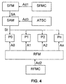
- Figure 3 shows a block diagram of the proposed block matching architecture for serial search stripe data flow.
- the search frame is stored in the search frame memory SFM, the reference frame in the reference frame memory RFM.
- the search frame memory SFM is controlled by a control unit SFMC by supplying addresses Ad1
- the reference frame memory REM is controlled by a control unit RFMC by supplying addresses Ad2.
- the current search area SA is loaded from the search frame memory SFM into the search area memory SAM.
- a control unit ATSC supplies addresses Ad3 to the search area memory SAM in order to convert the current search area into stripes. In steps of one picture element the stripes are piped through the k processing elements P0, P1, ..., Pk.
- the processing elements are arranged in serial order and are loaded with k macroblocks, beginning with A 0 ,..., A k-1 , in order to calculate the cost function. After processing the complete search area of a macroblock the motion vector is determined for this macroblock and this processed block is substituted by an unprocessed block and so on until all macroblocks of the current frame are processed.
- Figure 4 shows a block diagram for a further embodiment with parallel search stripe data flow. Similar processing units are used, the only difference to the first embodiment shown in figure 3 is that the search stripes are supplied to the processing elemts in parallel order.
- the invention can advantageously be used for encoding of MPEG video signals but also applies to video signal encoding by other bit-rate saving algorithms.
- the invention can be implemented in any kind of digital recording devices like digital camcorders, DVD RAMs etc.
Landscapes
- Engineering & Computer Science (AREA)
- Multimedia (AREA)
- Signal Processing (AREA)
- Compression Or Coding Systems Of Tv Signals (AREA)
Abstract
For block motion estimation the current frames are divided
into blocks and the picture elements of each block are
compared with the picture elements within a search area of
a reference frame in order to determine a motion vector.
According to the invention the processing requirements are
reduced by parallel processing, wherein the search area
(SA) is separated into search area stripes (St0, St1,...)
with a width equal to the block width (n). The picture
elements of k neighboring blocks (A0,..., Ak-1) are
compared with the picture elements of the search area
stripes until the complete search area for a block has
been processed. A block, for which the complete search
area has been processed, is substituted by an unprocessed
block. In an advantageous manner, the lines of the current
frame are separated into block sections comprising k
neighboring blocks, wherein the horizontal width of the
block sections is equal to the horizontal width of the
search area (wh).
Description
- The invention relates to a method and an apparatus for block motion estimation, especially for MPEG2 encoder.
- For the compression of video sequences it is well known to make use of the high redundancy between successive frames. Especially the technique of block motion estimation is widely used, e.g. for encoding according to the MPEG2 Part 2: video standard as specified in ISO/IEC 13818-2.
- In this technique, the current frames are divided spatially into rectangular or square blocks consisting of n x m picture elements (pixels, pels). Than, a search for each block of the current frame is performed. For this purpose, the picture elements of each block are compared with the picture elements of a block within a search area of a reference frame. A cost function, i.e. a measure of the match between the compared blocks, is calculated for all search positions. The actual motion vector is defined by the relative positions of the two blocks where the cost function has the minimum value.
- Using the most common cost function, the mean of the absolute difference (mad) between current block and candidate block from the reference frame,about n x m subtractions, absolute value calculations and additions have to be performed for each search position.

- For a 13.5 MHz video signal (horizontal resolution Wframe,h = 720 pel, vertical resolution Wframe,v = 576 pel, frame rate fframe = 25 Hz) and the following typical parameter set for the blockmatching process:
- Horizontal search range
- sh = +/- 64 pel
- Vertical search range
- sv = +/- 32 pel
- Horizontal block size
- n = 16 pel
- Vertical block size
- m = 16 pel
- Techniques are known, where the processing power is reduced by using only a fraction of the picture elements in the macro blocks and search area, respectively. The use of Quincunx subsampling as such method is described for example in DE-A-19509418. However, the rate of subsampling is limited due to the necessary accuracy of the motion estimation.
- The invention is based on the object of specifying a method for block motion estimation with reduced implementation requirements e.g. for real-time motion estimation. This object is achieved by means of the method specified in
claim 1. - It is a further object of the invention to disclose an apparatus which utilises the inventive method. This object is achieved by the apparatus disclosed in claim 7.
- The above calculated computational demand can be fulfilled for real-time motion estimation only by massive parallel processing of the cost function. If a parallel search on several independent search areas is performed, the required communication bandwidth between the memories storing the search areas and the arithmetic unit performing the cost function calculation would grow linear with the number of parallel processed searches. However, this is not true, if neighbouring blocks of the current frame are fed to several processing elements, wherein the processing elements perform the search for these blocks on a common search area.
- In principle, the method for block motion estimation consists in the fact that
- the search area is separated into search area stripes with a width equal to the width of the blocks;
- the picture elements of k neighbouring blocks are compared with the picture elements of the search area stripes until the complete search area for a block has been processed;
- the block, for which the complete search area has been processed, is substituted by an unprocessed block.
- In an advantageous manner, the lines of the current frame are separated into block sections comprising k neighbouring blocks which are processed in parallel, wherein the horizontal width of the block sections is equal to the horizontal width of the search area.
- Also, it may be particularly advantageous if the search area stripes have a vertical width equal to the vertical width of the search area.
- In an advantageous development the picture elements of the search area stripes are compared in parallel (Fig. 4) with the picture elements of the k neighbouring blocks.
- In a further advantageous development the picture elements of the search area stripes are compared in serial (Fig. 3) with the picture elements of the k neighbouring blocks.
- Furthermore, it may be particularly advantageous if the block motion estimation is part of an MPEG encoding of video signals and the blocks are macroblocks with a horizontal and vertical macroblock size of 16 picture elements.
- In principle, the apparatus for image motion estimation, includes:
- first means for controlling the conversion of the search area into search stripes;
- k processing elements which are loaded with k neighbouring blocks for comparing with the picture elements of the search area stripes;
- means for substituting a block, for which the complete search area has been processed by an unprocessed block.
- In an advantageous manner, the apparatus further comprises:
- a search frame memory;
- a reference frame memory;
- second means for controlling the search frame memory;
- third means for controlling the reference frame memory;
- a search area memory, in which the current search area is loaded from the search frame memory.
- In an advantageous development the processing elements are arranged in serial order.
- In a further advantageous development the processing elements are arranged in parallel order.
- Exemplary embodiments of the invention are described with reference to the figures. These show in:
- Figure 1
- the division of a frame into macroblocks (a) and the overlapping search areas for neighbouring macroblocks (b);
- Figure 2
- a search scheme for parallel processing of k neighbouring macroblocks;
- Figure 3
- a block diagram for serial search stripe data flow;
- Figure 4
- a block diagram for parallel search stripe data flow.
- Figure 1a) illustrates the division of a current frame into h x v macroblocks MB0, MB1, MBh-1, etc. with a horizontal macroblock size of n picture elements and a vertical macroblock size of m picture elements. Within the reference frame, which is also named search frame and can be a preceding or a following frame, a search area is assigned to each of the macroblocks. For an example of three neighboring macroblocks MBr, MBs, MBt the respective search areas overlap as shown in figure 1b). A first part Sr of the search area of macroblock MBr is only used for macroblock MBr, a second part Srs is also used for macroblock MBs and finally a third part Srst is used for macroblocks MBr, MBs, MBt. The search area for macroblock MBs comprises besides the already mentioned parts Srs and Srst a further part Sst which is also used for the macroblock MBs but not for MBr. Similar besides parts Srst and Sst a third part St exists which is only used for the macroblock MBt.
- According to the invention the processing scheme of figure 2 can be applied. The macroblock lines of the current frame are separated into sections consisting of k macroblocks A0,..., Ak-1, B0,..., Bk-1, C0,... as shown in figure 2a). The value of k depends on the search range width sh,sv and the size n,m of the macroblocks as follows. First, sh,max and sv,max are defined to be the maximum absolute value of sh and sv, respectively. The horizontal width wh of the search area and the vertical width wv of the search area are
- Now, k can be calculated to

- The reference frame is separated into search area stripes St0, St1,... with a horizontal width of n and a vertical width of wv . At the beginning of the processing of a macroblock line, the current macroblocks A0 to Ak-1 are loaded into the k processing elements. Subsequent, the search area stripes of the reference frame are piped through the processing elements. After processing of one stripe, new search stripes are generated which are shifted compared to the former search stripes by one picture element. These search area stripes are also piped through the processing elements and so on until the complete search area for macroblock A0 has been processed and the minimum of the cost function can be calculated. Afterwards, macroblock A0 is substituted by the first macroblock B0 of the next macroblock section. Similar, when the processing of macroblock A1 is finished, it is substituted by macroblock B1 of the following section. This scheme is applied until the end of the macroblock line of the current frame.
- The bandwidth requirement of the described processing scheme can be calculated as follows. With exception of the last search area stripe, the processing for one search area stripe requires n·wv accesses to memory words consisting of n pels. The processing of the last search area stripe requires wv accesses to memory words consisting of n pels. The total number nsas of search area stripes is the horizontal resolution wframe,h of the current frame divided by the horizontal size n of the macroblocks.

- This totals to a number of accesses na,mbl for the processing of one macroblock line:
- The number of macroblock lines nmbl,frame within a frame can be calculated to

- The total number of accesses na,frame for one frame to the reference data memory is

- For the above used example with a horizontal resolution wframe,h = 720 pel, a vertical resolution wframe,v = 576 pel, a vertical search range sv = +/-32 pel, and m = 16 for the vertical size of the macroblocks (wv = 80), na,frame equals to appr. 2.03 million accesses to a n byte wide vector of pels per frame. With n = 16 for the horizontal size of the macroblocks and a frame rate of 25 Hz, the total required bandwidth for the reference frame memory is in the order of 812 million bytes/s. Assuming a 8 byte vector-organized data access, the final clock rate for the reference frame memory is less than 102 MHz. This clock rate can be achieved easily with today CMOS VLSI technology.
- Figure 3 shows a block diagram of the proposed block matching architecture for serial search stripe data flow. The search frame is stored in the search frame memory SFM, the reference frame in the reference frame memory RFM. The search frame memory SFM is controlled by a control unit SFMC by supplying addresses Ad1, the reference frame memory REM is controlled by a control unit RFMC by supplying addresses Ad2. The current search area SA is loaded from the search frame memory SFM into the search area memory SAM. A control unit ATSC supplies addresses Ad3 to the search area memory SAM in order to convert the current search area into stripes. In steps of one picture element the stripes are piped through the k processing elements P0, P1, ..., Pk. The processing elements are arranged in serial order and are loaded with k macroblocks, beginning with A0,..., Ak-1, in order to calculate the cost function. After processing the complete search area of a macroblock the motion vector is determined for this macroblock and this processed block is substituted by an unprocessed block and so on until all macroblocks of the current frame are processed.
- Figure 4 shows a block diagram for a further embodiment with parallel search stripe data flow. Similar processing units are used, the only difference to the first embodiment shown in figure 3 is that the search stripes are supplied to the processing elemts in parallel order.
- The invention can advantageously be used for encoding of MPEG video signals but also applies to video signal encoding by other bit-rate saving algorithms.
- The invention can be implemented in any kind of digital recording devices like digital camcorders, DVD RAMs etc.
Claims (10)
- Method for block motion estimation, in which a current frame is divided into blocks of picture elements which are compared with picture elements within the search area (Sr, Srs, Srst Sst, St) of a reference frame and wherein thereof a motion information for the blocks is determined, characterized in thatthe search area is separated into search area stripes (St0, St1,...) with a width equal to the width of the blocks (n);the picture elements of k neighbouring blocks (A0, ..., Ak-1) are compared with the picture elements of the search area stripes until the complete search area for a block (A0) has been processed;the block (A0), for which the complete search area has been processed, is substituted by an unprocessed block (B0).
- Method according to claim 1, wherein the lines of the current frame are separated into block sections comprising k neighbouring blocks which are processed in parallel and wherein the horizontal width of the block sections is equal to the horizontal width (Wh) of the search area.
- Method according to claim 2, wherein in that the search area stripes have a vertical width equal to the vertical width (Wv) of the search area.
- Method according to any of claims 1 to 3, wherein the picture elements of the search area stripes are compared in parallel (Fig. 4) with the picture elements of the k neighbouring blocks (A0, ..., Ak-1).
- Method according to any of claims 1 to 3, wherein the picture elements of the search area stripes are compared in serial (Fig. 3) with the picture elements of the k neighbouring blocks (A0, ..., Ak-1).
- Method according to any of the preceding claims, wherein the block motion estimation is part of an MPEG encoding of video signals and the blocks are macroblocks with a horizontal and vertical macroblock size of 16 picture elements.
- Apparatus for image motion estimation for a method according to any of the preceding claims, including:first means (ATSC) for controlling the conversion of the search area into search stripes;k processing elements (P0, P1, ..., Pk) which are loaded with k neighbouring blocks for comparing with the picture elements of the search area stripes;means for substituting a block (A0), for which the complete search area has been processed by an unprocessed block (B0).
- Apparatus according to claim 7, further comprising:a search frame memory (SFM);a reference frame memory (RFM);second means (SFMC) for controlling the search frame memory (SFM);third means (RFMC) for controlling the reference frame memory (RFM);a search area memory (SAM), in which the current search area is loaded from the search frame memory (SFM).
- Apparatus according to claim 7 or 8, wherein the processing elements are arranged in serial order.
- Apparatus according to claim 7 or 8, wherein the processing elements are arranged in parallel order.
Priority Applications (4)
| Application Number | Priority Date | Filing Date | Title |
|---|---|---|---|
| EP99110116A EP1056293A1 (en) | 1999-05-25 | 1999-05-25 | Method and apparatus for block motion estimation |
| EP00110315A EP1061747A1 (en) | 1999-05-25 | 2000-05-13 | Method and apparatus for block motion estimation |
| JP2000151319A JP2000354245A (en) | 1999-05-25 | 2000-05-23 | Method and device for estimating block movement |
| CN 00107707 CN1275033A (en) | 1999-05-25 | 2000-05-23 | Method and device for estimation of block movement |
Applications Claiming Priority (1)
| Application Number | Priority Date | Filing Date | Title |
|---|---|---|---|
| EP99110116A EP1056293A1 (en) | 1999-05-25 | 1999-05-25 | Method and apparatus for block motion estimation |
Publications (1)
| Publication Number | Publication Date |
|---|---|
| EP1056293A1 true EP1056293A1 (en) | 2000-11-29 |
Family
ID=8238235
Family Applications (1)
| Application Number | Title | Priority Date | Filing Date |
|---|---|---|---|
| EP99110116A Withdrawn EP1056293A1 (en) | 1999-05-25 | 1999-05-25 | Method and apparatus for block motion estimation |
Country Status (3)
| Country | Link |
|---|---|
| EP (1) | EP1056293A1 (en) |
| JP (1) | JP2000354245A (en) |
| CN (1) | CN1275033A (en) |
Cited By (1)
| Publication number | Priority date | Publication date | Assignee | Title |
|---|---|---|---|---|
| WO2005088537A1 (en) * | 2004-03-17 | 2005-09-22 | Nokia Corporation | Electronic device and a method in an electronic device for processing image data |
Families Citing this family (3)
| Publication number | Priority date | Publication date | Assignee | Title |
|---|---|---|---|---|
| JP4114859B2 (en) * | 2002-01-09 | 2008-07-09 | 松下電器産業株式会社 | Motion vector encoding method and motion vector decoding method |
| CN100581259C (en) * | 2002-01-09 | 2010-01-13 | 松下电器产业株式会社 | Motion vector coding method and device |
| EP2104356A1 (en) * | 2008-03-18 | 2009-09-23 | Deutsche Thomson OHG | Method and device for generating an image data stream, method and device for reconstructing a current image from an image data stream, image data stream and storage medium carrying an image data stream |
Citations (1)
| Publication number | Priority date | Publication date | Assignee | Title |
|---|---|---|---|---|
| US5784108A (en) * | 1996-12-03 | 1998-07-21 | Zapex Technologies (Israel) Ltd. | Apparatus for and method of reducing the memory bandwidth requirements of a systolic array |
-
1999
- 1999-05-25 EP EP99110116A patent/EP1056293A1/en not_active Withdrawn
-
2000
- 2000-05-23 JP JP2000151319A patent/JP2000354245A/en active Pending
- 2000-05-23 CN CN 00107707 patent/CN1275033A/en active Pending
Patent Citations (1)
| Publication number | Priority date | Publication date | Assignee | Title |
|---|---|---|---|---|
| US5784108A (en) * | 1996-12-03 | 1998-07-21 | Zapex Technologies (Israel) Ltd. | Apparatus for and method of reducing the memory bandwidth requirements of a systolic array |
Non-Patent Citations (2)
| Title |
|---|
| ARTIERI A ET AL: "A CHIP SET CORE FOR IMAGE COMPRESSION", IEEE TRANSACTIONS ON CONSUMER ELECTRONICS, vol. 36, no. 3, 1 August 1990 (1990-08-01), pages 395 - 402, XP000162866, ISSN: 0098-3063 * |
| DE SA L ET AL: "A PARALLEL ARCHITECTURE FOR REAL-TIME VIDEO CODING", MICROPROCESSING AND MICROPROGRAMMING, vol. 30, no. 1 / 05, 1 August 1990 (1990-08-01), pages 439 - 445, XP000141680, ISSN: 0165-6074 * |
Cited By (1)
| Publication number | Priority date | Publication date | Assignee | Title |
|---|---|---|---|---|
| WO2005088537A1 (en) * | 2004-03-17 | 2005-09-22 | Nokia Corporation | Electronic device and a method in an electronic device for processing image data |
Also Published As
| Publication number | Publication date |
|---|---|
| CN1275033A (en) | 2000-11-29 |
| JP2000354245A (en) | 2000-12-19 |
Similar Documents
| Publication | Publication Date | Title |
|---|---|---|
| US6859494B2 (en) | Methods and apparatus for sub-pixel motion estimation | |
| KR100658181B1 (en) | Video decoding method and apparatus | |
| US5781249A (en) | Full or partial search block matching dependent on candidate vector prediction distortion | |
| US6078618A (en) | Motion vector estimation system | |
| US5587741A (en) | Apparatus and method for detecting motion vectors to half-pixel accuracy | |
| US20070165716A1 (en) | Signal processing device, image capturing device, network camera system and video system | |
| US20040114688A1 (en) | Device for and method of estimating motion in video encoder | |
| US6249612B1 (en) | Device and method for image coding | |
| US6400764B1 (en) | Motion estimation method featuring orthogonal-sum concurrent multi matching | |
| EP0722252B1 (en) | Boundary matching motion estimation apparatus | |
| US20090232201A1 (en) | Video compression method and apparatus | |
| US20080192985A1 (en) | Motion detection device, MOS (metal-oxide semiconductor) integrated circuit, and video system | |
| US6480629B1 (en) | Motion estimation method using orthogonal-sum block matching | |
| EP1061747A1 (en) | Method and apparatus for block motion estimation | |
| US6574370B1 (en) | Image encoding system | |
| EP1056293A1 (en) | Method and apparatus for block motion estimation | |
| JPH10215457A (en) | Moving image decoding method and device | |
| EP1819173B1 (en) | Motion vector predictive encoding apparatus and decoding apparatus | |
| US5710603A (en) | Method for detecting motion vectors | |
| KR19980036073A (en) | Motion vector detection method and apparatus | |
| US6480544B1 (en) | Encoding apparatus and encoding method | |
| Song et al. | Towards a multi-terminal video compression algorithm using epipolar geometry | |
| JPH09284777A (en) | Video coding method and device using motion compensation without motion vector | |
| KR100551952B1 (en) | Method for Motion Searching of Image Compression | |
| JP3309519B2 (en) | Motion vector detection device |
Legal Events
| Date | Code | Title | Description |
|---|---|---|---|
| PUAI | Public reference made under article 153(3) epc to a published international application that has entered the european phase |
Free format text: ORIGINAL CODE: 0009012 |
|
| AK | Designated contracting states |
Kind code of ref document: A1 Designated state(s): AT BE CH CY DE DK ES FI FR GB GR IE IT LI LU MC NL PT SE |
|
| AX | Request for extension of the european patent |
Free format text: AL;LT;LV;MK;RO;SI |
|
| AKX | Designation fees paid | ||
| REG | Reference to a national code |
Ref country code: DE Ref legal event code: 8566 |
|
| STAA | Information on the status of an ep patent application or granted ep patent |
Free format text: STATUS: THE APPLICATION IS DEEMED TO BE WITHDRAWN |
|
| 18D | Application deemed to be withdrawn |
Effective date: 20010530 |