EP1052945B1 - Tubular medical instrument - Google Patents
Tubular medical instrument Download PDFInfo
- Publication number
- EP1052945B1 EP1052945B1 EP99973250A EP99973250A EP1052945B1 EP 1052945 B1 EP1052945 B1 EP 1052945B1 EP 99973250 A EP99973250 A EP 99973250A EP 99973250 A EP99973250 A EP 99973250A EP 1052945 B1 EP1052945 B1 EP 1052945B1
- Authority
- EP
- European Patent Office
- Prior art keywords
- transmission element
- tubular shaft
- tubular
- shaft
- force transmission
- Prior art date
- Legal status (The legal status is an assumption and is not a legal conclusion. Google has not performed a legal analysis and makes no representation as to the accuracy of the status listed.)
- Expired - Lifetime
Links
Images

Classifications
-
- A—HUMAN NECESSITIES
- A61—MEDICAL OR VETERINARY SCIENCE; HYGIENE
- A61B—DIAGNOSIS; SURGERY; IDENTIFICATION
- A61B17/00—Surgical instruments, devices or methods, e.g. tourniquets
- A61B17/28—Surgical forceps
- A61B17/29—Forceps for use in minimally invasive surgery
- A61B17/295—Forceps for use in minimally invasive surgery combined with cutting implements
-
- A—HUMAN NECESSITIES
- A61—MEDICAL OR VETERINARY SCIENCE; HYGIENE
- A61B—DIAGNOSIS; SURGERY; IDENTIFICATION
- A61B17/00—Surgical instruments, devices or methods, e.g. tourniquets
- A61B17/28—Surgical forceps
- A61B17/29—Forceps for use in minimally invasive surgery
- A61B2017/2901—Details of shaft
- A61B2017/2902—Details of shaft characterized by features of the actuating rod
-
- A—HUMAN NECESSITIES
- A61—MEDICAL OR VETERINARY SCIENCE; HYGIENE
- A61B—DIAGNOSIS; SURGERY; IDENTIFICATION
- A61B17/00—Surgical instruments, devices or methods, e.g. tourniquets
- A61B17/28—Surgical forceps
- A61B17/29—Forceps for use in minimally invasive surgery
- A61B2017/2901—Details of shaft
- A61B2017/2904—Details of shaft curved, but rigid
-
- A—HUMAN NECESSITIES
- A61—MEDICAL OR VETERINARY SCIENCE; HYGIENE
- A61B—DIAGNOSIS; SURGERY; IDENTIFICATION
- A61B90/00—Instruments, implements or accessories specially adapted for surgery or diagnosis and not covered by any of the groups A61B1/00 - A61B50/00, e.g. for luxation treatment or for protecting wound edges
- A61B90/08—Accessories or related features not otherwise provided for
- A61B2090/0813—Accessories designed for easy sterilising, i.e. re-usable
-
- A—HUMAN NECESSITIES
- A61—MEDICAL OR VETERINARY SCIENCE; HYGIENE
- A61B—DIAGNOSIS; SURGERY; IDENTIFICATION
- A61B2217/00—General characteristics of surgical instruments
- A61B2217/002—Auxiliary appliance
- A61B2217/005—Auxiliary appliance with suction drainage system
-
- A—HUMAN NECESSITIES
- A61—MEDICAL OR VETERINARY SCIENCE; HYGIENE
- A61B—DIAGNOSIS; SURGERY; IDENTIFICATION
- A61B2217/00—General characteristics of surgical instruments
- A61B2217/002—Auxiliary appliance
- A61B2217/007—Auxiliary appliance with irrigation system
-
- A—HUMAN NECESSITIES
- A61—MEDICAL OR VETERINARY SCIENCE; HYGIENE
- A61B—DIAGNOSIS; SURGERY; IDENTIFICATION
- A61B90/00—Instruments, implements or accessories specially adapted for surgery or diagnosis and not covered by any of the groups A61B1/00 - A61B50/00, e.g. for luxation treatment or for protecting wound edges
- A61B90/70—Cleaning devices specially adapted for surgical instruments
Definitions
- the invention relates to a medical tubular shaft instrument, with an elongate tubular shaft, with at least one movable tool at the distal end, further comprising at least one movable handle portion at the proximal end, and finally with an elongate force transmission element, the distal end with the at least one tool and its proximal end is frictionally connected to the at least one movable grip part, wherein the force transmission element extends through the tubular shaft.
- tubular instruments are used in minimally invasive surgery as surgical instruments to perform surgical procedures through a small incision under endoscopic control.
- such tubular shaft instruments are provided with different functions.
- the at least one movable tool can be embodied, for example, in the form of a movable jaw part which has a cutting edge which interacts with a cutting edge of a second movable or immovable jaw part in a cutting manner.
- the at least one movable tool may also be a jaw member having a blunt surface which cooperates with a second jaw member for grasping tissue.
- the at least one movable tool has a configuration which makes it possible to hold a needle in the operating area with this tool and to guide the formation of a seam for joining tissue.
- At least one movable grip part is provided at the proximal end of the tubular shaft instrument, which is non-positively connected to the at least one movable tool via an elongate force transmission element, for example in the form of a pull rod. Movement of the movable handle portion then causes movement of the at least one movable tool at the distal end of the tubular shaft to perform the corresponding function, For example, cutting or holding and guiding the needle through the tissue to effect.
- tubular shaft instruments In the context of minimally invasive surgery, it may sometimes be necessary to design such tubular shaft instruments with a tubular shaft diameter that is about 3 mm or less. Such small tubular shaft diameters are particularly required in the operation on infants or even in operations in certain operating areas, such as in the head area.
- the force transmission element is adapted in diameter to the inner diameter of the tubular shaft, i. the outer diameter of the force transmission element is about as large as the inner diameter of the tubular shaft, so that the force transmission element completely fills the interior of the tubular shaft.
- the disadvantage of this embodiment is that the interior of the tubular shaft can not be sufficiently flush with built-in power transmission element, as between the power transmission element and the tubular shaft no sufficient passage for a rinsing liquid is present.
- miniaturized tubular shaft instruments are not disassembled in the way, at least not so easily dismantled that the power transmission element for cleaning out of the tubular shaft can be removed, because the connection between the at least one movable tool and the power transmission element on the one hand and the power transmission element and the at least one movable handle part on the other hand is not or not easily solved, this means that the known tubular shaft instruments only insufficiently cleanable. Therefore, accumulating during an operation in the interior of the tubular shaft contaminants can not be removed so far that this Rohrschaftinstrumente can meet the strict sterility and hygiene requirements.
- a surgical instrument is known from the German utility model DE-4-7330291, in which spacer balls or rollers are placed on the shaft at certain intervals in order to make it stand in the carbon shaft.
- the invention is therefore the object of developing a tubular shaft instrument of the type mentioned in that the tubular shaft instrument by flushing the interior of the tubular shaft with built-in power transmission element is easy to clean, and that the stability of the tubular shaft instrument is still guaranteed against bending of the tubular shaft.
- this object is achieved with respect to the above-mentioned Rohrschaftinstrumentes that the force transmission element at least in its extending through the tubular shaft region at least partially extends radially at least three circumferential points to an inner wall of the tubular shaft and has a clearance between the three circumferential locations of the inner wall , And in its remaining, extending through the tubular shaft sections at least partially having a clear distance from the inner wall.
- the force transmission element at least partially in its extending through the tubular shaft region has a clear distance from the inner wall of the tubular shaft, so that the interior of the tubular shaft has a purge area sufficient for cleaning even with a built-in force transmission element.
- the invention provides that the force transmission element axially at least partially extends at least three circumferential locations radially up to the inner wall of the tubular shaft.
- the power transmission element also has the task to stabilize the tubular shaft against bending during the transmission of high tensile forces.
- the design of the force transmission element characterized in that this extends at least partially radially at three circumferential points to the inner wall of the tubular shaft and thereby stabilizes the tubular shaft.
- the power transmission element in these sections between the circumferential locations to the inner wall of the tubular shaft on a clearance for the passage of a rinsing liquid.
- the force transmission element according to the present invention in the axial sections, where the force transmission element extends to the inner wall of the tubular shaft be formed in cross-section approximately triangular.
- the tubular shaft instrument according to the invention is easy to clean due to the continuous between the force transmission element and the tubular shaft through flushing channel, and despite the existing continuous Spülraumes occurs no loss of stability of the tubular shaft.
- the at least three extend radially up to the inner wall of the tubular shaft Circumferential points continuously over the entire, extending through the tubular shaft portion of the power transmission element.
- the at least three circumferential points extend not only in sections over the force transmission element, but over the entire extending in the tubular shaft region of the force transmission element.
- the advantage is achieved that the tubular shaft undergoes stabilization through the force transmission element over its entire length.
- the manufacture of the power transmission element is simplified.
- the force transmission element may be formed of a cylindrical solid material by introducing at least three continuous flats or depressions in the axial direction in a material-removing process, for example by laser techniques or spark erosion, or in a non-abrasive process, for example by rolling or profiling, i. Shapes are made by pulling a round material through a corresponding die.
- the force transmission element is rounded at the at least three circumferential locations.
- the radius of curvature of the circumferential points is smaller than the inner radius of the tubular shaft.
- the force transmission element rests with its at least three circumferential points only linearly on the inner wall of the tubular shaft, whereby the friction is minimized in the axial reciprocating movement of the power transmission element in the tubular shaft during use of the tubular shaft instrument.
- the existing for the passage of a rinsing liquid flushing cross section between the power transmission element and the tubular shaft is increased, and it will be minimized for the rinse liquid hard to reach areas between the outer contour of the force transmission element and the inner wall of the tubular shaft.
- the force transmission element between the at least three circumferential locations is recessed concave toward the longitudinal center axis of the power transmission element.
- the at least three circumferential points extending radially as far as the inner wall of the tubular shaft extend in a straight line.
- the force transmission element can be produced easily, although it can also be considered that the at least three circumferential points extend helically around the longitudinal central axis of the force transmission element.
- the at least three circumferential locations occupy an equal angular distance from one another.
- This configuration achieves optimum all-round and symmetrical support of the force transmission element on the inner wall of the tubular shaft.
- the inventive design of the tubular shaft instrument can be used in a pair of pliers for cutting and / or grasping as well as a needle holder.
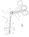
- Fig. 1 is provided with the general reference numeral 10 provided medical tubular shaft instrument.
- the medical tubing instrument 10 is, according to the embodiment shown, a medical forceps 12 for cutting tissue in the human or animal body.
- the forceps 12 has at least one movable tool 14 at the distal end.
- the tool 14 is a movable jaw member 16 which cooperates with another jaw member 18, which in this case is immobile but may also be movable.
- the two jaws 16 and 18 are attached to the distal end of a tubular shaft 20.
- the tubular shaft 20 is designed as a hollow cylinder.
- the tubular shaft 20 has in the present Furthermore, case has an outer diameter of about 3 mm or less.
- the tubular shaft 20 is still rigid.
- the handle 22 has at least one movable handle portion 24 which facilitates actuation of the at least one movable tool 14, i. here of a jaw 16, serves.
- the movable handle part 24 is connected via a hinge 26 hingedly connected to a stationary, with the tubular shaft 20 firmly connected handle portion 28.
- a force transmission element 30 is provided, which is indicated in Fig. 1 by broken lines and in Fig. 2 and 4 shown in more detail.
- the power transmission element 30 is interposed between the at least one movable tool 14, i. here the movable jaw part 16 and the at least one movable grip part 24 connected. More specifically, a distal end 32 of the power transmission member 30 is connected to the movable jaw member 16 and a proximal end 34 of the power transmission member 30 is connected to the movable handle member 24.
- the power transmission element 30 extends through the tubular shaft 20, i. is disposed in the tubular shaft 20.
- the power transmission element 30 operates to close the jaw members 16 and 18 to train, ie from the open position of the movable jaw member shown in Fig. 1 with broken lines 16, which corresponds to the broken line position of the movable handle portion 24, is pulled proximally by moving the movable handle portion 24 onto the stationary handle portion 28 toward the force transmitting member 30 in the tubular shaft 20, thereby closing the movable jaw portion 16 against the stationary jaw portion 18 becomes.
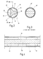
- the force transmission element 30 at least in its extending through the tubular shaft 20 region an outer contour 36 which axially at least partially at least three circumferential locations , which are designated in Fig. 2 with 38, 40 and 42, extends radially to an inner wall 44 of the tubular shaft 20 and thereby ensures an all-round support of the tubular shaft 20.
- the at least three peripheral locations 38, 40 and 42 are provided on two axial sections 46 and 48 of the force transmission element 30.
- Fig. 4 illustrates only an axial section of the tubular shaft 20 and the power transmission element 30, it is understood that such portions are provided in greater numbers at least in the extending through the tubular shaft 20 portion of the force transmission element 30.
- the circumferential points 38, 40 and 42 extending radially to the inner wall 44 of the tubular shaft 20 extend over an axial partial length of the power transmission element 30.
- the force transmission element 30 no to the inner wall 44 of the tubular shaft 20 reaching and supporting at this circumferential points, the force transmission element 30 at least partially a clear distance from the inner wall 44, as shown in Fig. 4 with a portion 50 is exemplified, in which the force transmission element 30 on all sides a clearance from the inner wall 44 of the tubular shaft 20 has.
- the power transmission element 30 has a substantially triangular cross-section in the sections 46 and 48 and the other portions corresponding to these sections
- the power transmission element 30 in the section 50 and the other portions corresponding to this section 50 may have a substantially circular cross-section, wherein the round Cross-section in the portion 50 and the other portions corresponding to this section 50 has a smaller diameter than the inner wall 44 of the tubular shaft 20th
- the circumferential locations 38, 40 and 42 supported on the inner wall 44 of the tubular shaft 20 extend continuously over the entire length extending through the tubular shaft 20 Range of the force transmission element 30 humiliatrekken. This is shown in Fig. 4 with broken lines. In other words, then the power transmission element 30 at any axial position has a cross-section, as shown in Fig. 2.
- the formed in the form of webs circumferential locations 38, 40, 42 extend between the proximal end 34 and the distal end 32 in a straight line. However, it can also be provided a coiled configuration.
- each a clear space 52, 54, 56 is provided, which serves as a purge passage for the passage of a rinsing liquid.
- the usable as flushing channels spaces 52, 54, 56 thus extend over the entire length of the arranged in the tubular shaft 20 portion of the power transmission element 30th
- the force transmission element 30 is rounded.
- the radius of curvature of the peripheral locations 38, 40, 42 is smaller than the inner radius of the tubular shaft 20.
- circumferential locations 38, 40 and 42 are each at an angular distance of about 120 °, i. they take an equal angular distance from each other, whereby a uniform all-round support of the power transmission element 30 is achieved on the inner wall 44 of the tubular shaft 20.
- the power transmission element 30 is made entirely solid from a solid material, for example. From a cylindrical body, in which in the outer contour according to the embodiment in Fig. 2nd By material-removing shaping, for example. By a laser process or a spark erosion process, recesses are partially introduced. Alternatively, the power transmission element 30 with the illustrated shape in a non-material-removing process by rolling or by profile drawing, ie forms by pulling a round material by a corresponding die, are produced, the latter is preferably applied.
- FIG. 3 illustrates an embodiment of a force transmission element 30 'known from the prior art, which is arranged in a tubular shaft 20'.
- This conventional power transmission element 30 ' is like the interior of the tubular shaft 20' formed in cross section round, wherein the diameter of the force transmission element 30 'is substantially equal to the inner diameter of the tubular shaft 20'. Accordingly, no space for the passage of a rinsing liquid is present between the force transmission element 30 'and the tubular shaft 20', ie, the interior of the tubular shaft 20 'can not be rinsed. If the force transmission element 30 'were flattened on both sides to form a band on two opposite circumferential sides except for the broken lines shown in FIG.
- a sufficient flushing cross section between the force transmission element 30 and the tubular shaft 20 is provided by the illustrated in Fig. 2 inventive embodiment of the force transmission element 30, on the other hand prevent the radially reaching to the inner wall 44 of the tubular shaft 20 circumferential locations 38, 40 and 42, that the Power transmission element 30 jumps back and forth at the alternating tensile and compressive stresses and thus cause a stabilization of the tubular shaft 20, so that it does not bend even at high power loads.
- a medical Rohrschaftinstrument 60 is shown in the form of a needle holder 62, in which the invention is also applied advantageously.
- a needle is held for connecting tissue by means of a seam and passed through the tissue.
- the needle holder 62 at its distal end on two movable tools 64 and 66 in the form of two pincer-like jaw parts with which a needle, not shown, can be held and guided safely and firmly.
- the two movable tools 64 and 66 are arranged at the distal end of a tubular shaft 68, at the proximal end of which in turn a handle 70 is arranged, which in this case has two movable grip parts 72 and 74.
- the movable tools 64 and 66 are frictionally engaged with the via a power transmission member 76 extending through the tubular shaft 68 and a linkage connected to the power transmission member 76, which is composed of an axial rod 78, and two pivot levers 80 and 82 movable handle parts 72 and 74 connected.
- Axial rod 78 is biased to its maximum distal position by a leaf spring 83 engaging proximate pivot levers 80 and 82 to grip members 72 and 74.
- a compression spring 84 serves as overload protection, which is effective when an excessive force is exerted on the handle parts 72 and 74.
- the axial rod 78 By compressing the handle portions 72 and 74, the axial rod 78 is displaced proximally against the action of the leaf spring 83, whereby also the power transmission element 76 connected to the axial rod 78 is displaced proximally to close the tools 64 and 66.
- the force transmission element 76 now has, according to the invention, at least in its region extending through the tubular shaft 68, a configuration as is provided in FIG. 2 for the exemplary embodiment of the tubular shaft instrument 10 described above.
- a rinsing liquid for rinsing the interior of the tubular shaft 68 can pass between the force transmission element 76 and the tubular shaft 68.
- the stability of the tubular shaft 68 is not affected thereby, i. this is protected against bending, as already explained in the previous embodiment.
Landscapes
- Health & Medical Sciences (AREA)
- Surgery (AREA)
- Life Sciences & Earth Sciences (AREA)
- Biomedical Technology (AREA)
- Nuclear Medicine, Radiotherapy & Molecular Imaging (AREA)
- Engineering & Computer Science (AREA)
- Ophthalmology & Optometry (AREA)
- Heart & Thoracic Surgery (AREA)
- Medical Informatics (AREA)
- Molecular Biology (AREA)
- Animal Behavior & Ethology (AREA)
- General Health & Medical Sciences (AREA)
- Public Health (AREA)
- Veterinary Medicine (AREA)
- Surgical Instruments (AREA)
Abstract
Description
Die Erfindung betrifft ein medizinisches Rohrschaftinstrument, mit einem langerstreckten Rohrschaft, mit zumindest einem beweglichen Werkzeug am distalen Ende, weiterhin mit zumindest einem beweglichen Griffteil am proximalen Ende, und schließlich mit einem langerstreckten Kraftübertragungselement, dessen distales Ende mit dem zumindest einen Werkzeug und dessen proximales Ende mit dem zumindest einen beweglichen Griffteil kraftschlüssig verbunden ist, wobei sich das Kraftübertragungselement durch den Rohrschaft erstreckt.The invention relates to a medical tubular shaft instrument, with an elongate tubular shaft, with at least one movable tool at the distal end, further comprising at least one movable handle portion at the proximal end, and finally with an elongate force transmission element, the distal end with the at least one tool and its proximal end is frictionally connected to the at least one movable grip part, wherein the force transmission element extends through the tubular shaft.
Ein derartiges medizinisches Rohrschaftinstrument ist allgemein bekannt.Such a medical tubular shaft instrument is well known.
Derartige Rohrschaftinstrumente werden in der minimal-invasiven Chirurgie als Operationsinstrumente eingesetzt, um operative Eingriffe durch eine kleine Körperinzision unter endoskopischer Kontrolle durchzuführen. Für unterschiedliche durchzuführende operative Eingriffe im menschlichen oder tierischen Körper werden solche Rohrschaftinstrumente mit unterschiedlichen Funktionen ausgestattet.Such tubular instruments are used in minimally invasive surgery as surgical instruments to perform surgical procedures through a small incision under endoscopic control. For different surgical procedures to be performed in the human or animal body, such tubular shaft instruments are provided with different functions.
Unter einem Rohrschaftinstrument im Sinne der vorliegenden Erfindung wird demnach bspw. eine Zange zum Schneiden und/oder Fassen und/oder bspw. auch ein Nadelhalter verstanden. Das zumindest eine beweglichen Werkzeug kann demnach bspw. in Form eines beweglichen Maulteils ausgebildet sein, das eine Schneide aufweist, die mit einer Schneide eines zweiten beweglichen oder unbeweglichen Maulteils schneidend zusammenwirkt. Das zumindest eine bewegliche Werkzeug kann auch ein Maulteil sein, das eine stumpfe Fläche aufweist, die mit einem zweiten Maulteil zum Fassen von Gewebe zusammenwirkt. Im Falle eines Nadelhalters weist das zumindest eine bewegliche Werkzeug eine Ausgestaltung auf, die es ermöglicht, mit diesem Werkzeug eine Nadel im Operationsgebiet zu halten und zur Bildung einer Naht zum Verbinden von Gewebe zu führen.Under a tubular shaft instrument in the context of the present invention is therefore, for example, a pair of pliers for cutting and / or grasping and / or for example. Also understood a needle holder. Accordingly, the at least one movable tool can be embodied, for example, in the form of a movable jaw part which has a cutting edge which interacts with a cutting edge of a second movable or immovable jaw part in a cutting manner. The at least one movable tool may also be a jaw member having a blunt surface which cooperates with a second jaw member for grasping tissue. In the case of a needle holder, the at least one movable tool has a configuration which makes it possible to hold a needle in the operating area with this tool and to guide the formation of a seam for joining tissue.
Zur Betätigung des zumindest einen beweglichen Werkzeuges ist am proximalen Ende des Rohrschaftinstrumentes zumindest ein bewegliches Griffteil vorgesehen, das mit dem zumindest einen beweglichen Werkzeug über ein langerstrecktes Kraftübertragungselement, bspw. in Form einer Zugstange, kraftschlüssig verbunden ist. Eine Bewegung des beweglichen Griffteils bewirkt dann eine Bewegung des zumindest einen beweglichen Werkzeugs am distalen Ende des Rohrschafts, um die entsprechende Funktion, bspw. Schneiden oder Halten und Führen der Nadel durch das Gewebe, zu bewirken.To actuate the at least one movable tool, at least one movable grip part is provided at the proximal end of the tubular shaft instrument, which is non-positively connected to the at least one movable tool via an elongate force transmission element, for example in the form of a pull rod. Movement of the movable handle portion then causes movement of the at least one movable tool at the distal end of the tubular shaft to perform the corresponding function, For example, cutting or holding and guiding the needle through the tissue to effect.
Im Sinne der minimal-invasiven Chirurgie ist es mitunter erforderlich, solche Rohrschaftinstrumente mit einem Rohrschaftdurchmesser auszubilden, der etwa 3 mm oder weniger beträgt. Solch kleine Rohrschaftdurchmesser sind insbesondere bei der Operation an Kleinkindern oder auch bei Eingriffen in bestimmten Operationsbereichen, wie im Kopfbereich, geboten.In the context of minimally invasive surgery, it may sometimes be necessary to design such tubular shaft instruments with a tubular shaft diameter that is about 3 mm or less. Such small tubular shaft diameters are particularly required in the operation on infants or even in operations in certain operating areas, such as in the head area.
Bei den bekannten Rohrschaftinstrumenten, insbesondere solchen mit einem Durchmesser von etwa 3 mm und weniger, ist das Kraftübertragungselement im Durchmesser an den Innendurchmesser des Rohrschaftes angepaßt, d.h. der Außendurchmesser des Kraftübertragungselementes ist etwa so groß wie der Innendurchmesser des Rohrschaftes, so daß das Kraftübertragungselement den Innenraum des Rohrschaftes vollständig ausfüllt.In the known tubular shaft instruments, in particular those with a diameter of about 3 mm and less, the force transmission element is adapted in diameter to the inner diameter of the tubular shaft, i. the outer diameter of the force transmission element is about as large as the inner diameter of the tubular shaft, so that the force transmission element completely fills the interior of the tubular shaft.
Der Nachteil dieser Ausgestaltung besteht darin, daß der Innenraum des Rohrschaftes bei eingebautem Kraftübertragungselement nicht ausreichend gespült werden kann, da zwischen dem Kraftübertragungselement und dem Rohrschaft kein ausreichender Durchgang für eine Spülflüssigkeit vorhanden ist. Da solche miniaturisierten Rohrschaftinstrumente jedoch nicht in der Weise zerlegbar, zumindest nicht so leicht zerlegbar sind, daß das Kraftübertragungselement zum Reinigen aus dem Rohrschaft entnommen werden kann, weil die Verbindung zwischen dem zumindest einen beweglichen Werkzeug und dem Kraftübertragungselement einerseits und dem Kraftübertragungselement und dem zumindest einen beweglichen Griffteil andererseits nicht oder nicht leicht lösbar ist, bedeutet dies, daß die bekannten Rohrschaftinstrumente nur ungenügend reinigbar sind. Sich während einer Operation im Innenraum des Rohrschaftes ansammelnde Verschmutzungen können daher nicht soweit entfernt werden, daß diese Rohrschaftinstrumente den strengen Sterilitäts- und Hygieneanforderungen entsprechen können.The disadvantage of this embodiment is that the interior of the tubular shaft can not be sufficiently flush with built-in power transmission element, as between the power transmission element and the tubular shaft no sufficient passage for a rinsing liquid is present. However, since such miniaturized tubular shaft instruments are not disassembled in the way, at least not so easily dismantled that the power transmission element for cleaning out of the tubular shaft can be removed, because the connection between the at least one movable tool and the power transmission element on the one hand and the power transmission element and the at least one movable handle part on the other hand is not or not easily solved, this means that the known tubular shaft instruments only insufficiently cleanable. Therefore, accumulating during an operation in the interior of the tubular shaft contaminants can not be removed so far that this Rohrschaftinstrumente can meet the strict sterility and hygiene requirements.
Es wurde zur Verbesserung der Reinigungseigenschaften dieser Rohrschaftinstrumente in Betracht gezogen, das Kraftübertragungselement mit einem Außendurchmesser auszugestalten, der geringer ist als der Innendurchmesser des Rohrschaftes, so daß ein genügender Spülraum zwischen dem Kraftübertragungselement und dem Rohrschaft verbleibt. Dabei hat es sich jedoch als besonders nachteilig herausgestellt, daß sich der Rohrschaft bei hohen, von dem Kraftübertragungselement auf das zumindest eine bewegliche Werkzeug übertragenen Zugkräften trotz seiner starren Ausgestaltung verbiegt. Das Rohrschaftinstrument wird jedoch unbrauchbar, wenn der Rohrschaft verbogen ist. Der gleiche nachteilige Effekt stellte sich auch dann ein, wenn anstelle eines im Querschnitt runden Kraftübertragungselementes kleinen Durchmessers ein beidseitig abgeflachtes Zugband eingesetzt wurde. Auch ein Kraftübertragungselement in Form eines flachen Zugbandes führte zu einem Stabilitätsverlust des Rohrschaftes.It has been considered to improve the cleaning properties of these tubular shaft instruments to design the power transmission element with an outer diameter which is smaller than the inner diameter of the tubular shaft, so that a sufficient flushing space between the power transmission element and the tubular shaft remains. However, it has been found to be particularly disadvantageous that the tubular shaft bends at high, transmitted from the power transmission element to the at least one movable tool tensile forces despite its rigid configuration. However, the tubular shaft instrument becomes unusable when the tubular shaft is bent. The same disadvantageous effect also occurred when, instead of a cross-sectionally round force transmission element of small diameter, a tension band flattened on both sides was used. Also, a power transmission element in the form of a flat drawstring led to a loss of stability of the tubular shaft.
Aus dem dentschen Gebrauchmuster DE-4-7330291 ist ein Operations instrument bekannt, bei dem Abstandskugeln oder - rollen in gewissen Abständen auf dem Schaft aufgesetzt sind, um ihn im Kohlschaft zu fürhen.A surgical instrument is known from the German utility model DE-4-7330291, in which spacer balls or rollers are placed on the shaft at certain intervals in order to make it stand in the carbon shaft.
Der Erfindung liegt daher die Aufgabe zugrunde, ein Rohrschaftinstrument der eingangs genannten Art dahingehend weiterzubilden, daß das Rohrschaftinstrument durch Spülen des Innenraums des Rohrschaftes bei eingebautem Kraftübertragungselement leicht reinigbar ist, und daß die Stabilität des Rohrschaftinstrumentes gegen ein Verbiegen des Rohrschafts weiterhin gewährleistet ist.The invention is therefore the object of developing a tubular shaft instrument of the type mentioned in that the tubular shaft instrument by flushing the interior of the tubular shaft with built-in power transmission element is easy to clean, and that the stability of the tubular shaft instrument is still guaranteed against bending of the tubular shaft.
Erfindungsgemäß wird diese Aufgabe hinsichtlich des eingangs genannten Rohrschaftinstrumentes dadurch gelöst, daß das Kraftübertragungselement zumindest in seinem sich durch den Rohrschaft erstreckenden Bereich zumindest abschnittsweise an zumindest drei Umfangsstellen radial bis an eine Innenwand des Rohrschaftes reicht und zwischen den drei Umfangsstellen von der Innenwand einen lichten Abstand aufweist, und in seinen übrigen, sich durch den Rohrschaft erstreckenden Abschnitten zumindest teilumfänglich einen lichten Abstand von der Innenwand aufweist.According to the invention, this object is achieved with respect to the above-mentioned Rohrschaftinstrumentes that the force transmission element at least in its extending through the tubular shaft region at least partially extends radially at least three circumferential points to an inner wall of the tubular shaft and has a clearance between the three circumferential locations of the inner wall , And in its remaining, extending through the tubular shaft sections at least partially having a clear distance from the inner wall.
Erfindungsgemäß ist demnach zunächst vorgesehen, daß das Kraftübertragungselement zumindest in seinem sich durch den Rohrschaft erstreckenden Bereich durchgehend zumindest teilumfänglich einen lichten Abstand von der Innenwand des Rohrschaftes aufweist, so daß der Innenraum des Rohrschaftes auch bei eingebautem Kraftübertragungselement einen zur Reinigung ausreichenden Spülquerschnitt aufweist. Weiterhin ist erfindungsgemäß vorgesehen, daß das Kraftübertragungselement axial zumindest abschnittsweise an zumindest drei Umfangsstellen radial bis an die Innenwand des Rohrschaftes reicht. Insbesondere bei Rohrschaftinstrumenten mit einem Rohrschaftdurchmesser von etwa 3 mm und weniger hat sich nämlich die Erkenntnis eingestellt, daß bei solch dünnen Rohrschäften dem Kraftübertragungselement auch die Aufgabe zukommt, den Rohrschaft gegen ein Verbiegen bei der Übertragung hoher Zugkräfte zu stabilisieren. Dies wird bei dem erfindungsgemäßen Rohrschaftinstrument durch die Ausgestaltung des Kraftübertragungselementes dadurch gewährleistet, daß dieses zumindest abschnittsweise an drei Umfangsstellen radial bis an die Innenwand des Rohrschaftes reicht und den Rohrschaft dadurch stabilisiert. Um auch in diesen Abschnitten einen Durchgang für eine Spülflüssigkeit zu gewährleisten, weist das Kraftübertragungselement in diesen Abschnitten zwischen den Umfangsstellen zur Innenwand des Rohrschaftes einen lichten Abstand für den Durchtritt einer Spülflüssigkeit auf. Während es sich bei den im Stand der Technik in Betracht gezogenen Lösungen, das Kraftübertragungselement mit einem geringeren Durchmesser oder als flaches Band auszugestalten, herausgestellt hat, daß ein solches Kraftübertragungselement bei der Betätigung des Rohrschaftinstrumentes in dem Rohrschaft hin- und herspringt und somit ein Verbiegen des Rohrschaftes verursacht, wird ein solches Hin- und Herspringen bei dem erfindungsgemäßen Kraftübertragungselement durch die radial bis an dei Innenwand des Rohrschaftes reichenden Umfangsstellen vermieden. Gleichzeitig ist das Kraftübertragungselement des erfindungsgemäßen Rohrschaftinstrumentes selbst stabiler ausgebildet und kann daher höhere Zugkräfte übertragen als ein Zugband oder ein dünner Draht. Im einfachsten Fall kann das Kraftübertragungselement gemäß der vorliegenden Erfindung in den axialen Abschnitten, an denen das Kraftübertragungselement an die Innenwand des Rohrschaftes reicht, im Querschnitt etwa dreieckig ausgebildet sein. Das erfindungsgemäße Rohrschaftinstrument ist aufgrund des zwischen dem Kraftübertragungselement und dem Rohrschaft vorhandenen durchgehenden Spülkanal leicht reinigbar, und trotz des bestehenden durchgehenden Spülraumes tritt kein Stabilitätsverlust des Rohrschaftes auf.According to the invention, it is therefore initially provided that the force transmission element at least partially in its extending through the tubular shaft region has a clear distance from the inner wall of the tubular shaft, so that the interior of the tubular shaft has a purge area sufficient for cleaning even with a built-in force transmission element. Furthermore, the invention provides that the force transmission element axially at least partially extends at least three circumferential locations radially up to the inner wall of the tubular shaft. In particular, in tubular shaft instruments with a tubular shaft diameter of about 3 mm and less, namely, the realization has been adjusted that with such thin tubular shafts the power transmission element also has the task to stabilize the tubular shaft against bending during the transmission of high tensile forces. This is ensured in the tubular shaft instrument according to the invention by the design of the force transmission element, characterized in that this extends at least partially radially at three circumferential points to the inner wall of the tubular shaft and thereby stabilizes the tubular shaft. In order to get one in these sections too To ensure passage for a rinsing liquid, the power transmission element in these sections between the circumferential locations to the inner wall of the tubular shaft on a clearance for the passage of a rinsing liquid. While it is in the considered in the prior art solutions to design the power transmission element with a smaller diameter or as a flat band, has been found that such a force transmission element in the operation of the tubular shaft instrument in the tubular shaft reciprocates and thus a bending of the Tube shaft causes such a jumping back and forth is avoided in the force transmission element according to the invention by the radially reaching to the inner wall of the tubular shaft circumferential locations. At the same time, the power transmission element of the tubular shaft instrument according to the invention itself is more stable and can therefore transmit higher tensile forces than a drawstring or a thin wire. In the simplest case, the force transmission element according to the present invention in the axial sections, where the force transmission element extends to the inner wall of the tubular shaft, be formed in cross-section approximately triangular. The tubular shaft instrument according to the invention is easy to clean due to the continuous between the force transmission element and the tubular shaft through flushing channel, and despite the existing continuous Spülraumes occurs no loss of stability of the tubular shaft.
Somit wird die der Erfindung zugrundeliegende Aufgabe vollkommen gelöst.Thus, the problem underlying the invention is completely solved.
In einer bevorzugten Ausgestaltung erstrecken sich die zumindest drei radial bis an die Innenwand des Rohrschaftes reichenden Umfangsstellen durchgehend über den gesamten, sich durch den Rohrschaft erstreckenden Bereich des Kraftübertragungselementes.In a preferred embodiment, the at least three extend radially up to the inner wall of the tubular shaft Circumferential points continuously over the entire, extending through the tubular shaft portion of the power transmission element.
Bei dieser Ausgestaltung erstrecken sich die zumindest drei Umfangsstellen nicht nur abschnittsweise über das Kraftübertragungselement, sondern über den gesamten sich in dem Rohrschaft erstreckenden Bereich des Kraftübertragungselementes. Hierdurch wird der Vorteil erreicht, daß der Rohrschaft über seine gesamte Länge eine Stabilisierung durch das Kraftübertragungselement erfährt. Ein weiterer Vorteil besteht darin, daß die Herstellung des Kraftübertragungselementes vereinfacht wird. Beispielsweise kann das Kraftübertragungselement aus einem zylindrischen Vollmaterial durch Einbringen von zumindest drei durchgehenden Abflachungen oder Vertiefungen in axialer Richtung in einem materialabtragenden Verfahren, bspw. durch Lasertechniken oder Funkenerosion, oder in einem nicht materialabtragenden Verfahren, bspw. durch Rollen oder Profilziehen, d.h. Formen durch Ziehen eines Rundmaterials durch eine entsprechende Matrize, hergestellt werden.In this embodiment, the at least three circumferential points extend not only in sections over the force transmission element, but over the entire extending in the tubular shaft region of the force transmission element. As a result, the advantage is achieved that the tubular shaft undergoes stabilization through the force transmission element over its entire length. Another advantage is that the manufacture of the power transmission element is simplified. For example, the force transmission element may be formed of a cylindrical solid material by introducing at least three continuous flats or depressions in the axial direction in a material-removing process, for example by laser techniques or spark erosion, or in a non-abrasive process, for example by rolling or profiling, i. Shapes are made by pulling a round material through a corresponding die.
In einer weiteren bevorzugten Ausgestaltung ist das Kraftübertragungselement an den zumindest drei Umfangsstellen abgerundet.In a further preferred embodiment, the force transmission element is rounded at the at least three circumferential locations.
Hierbei ist von Vorteil, daß die zumindest drei bis an die Innenwand des Rohrschaftes reichenden Umfangsstellen des Kraftübertragungselementes im Langzeitgebrauch des Rohrschaftinstrumentes nicht in die Innenwand des Rohrschafts einschneiden, wie dies bei scharfen Kanten möglicherweise der Fall sein könnte.It is advantageous that the at least three reaching to the inner wall of the tubular shaft circumferential locations of the force transmission element in long-term use of the tubular shaft instrument does not cut into the inner wall of the tubular shaft, as might possibly be the case with sharp edges.
Dabei ist es bevorzugt, wenn der Krümmungsradius der Umfangsstellen kleiner ist als der Innenradius des Rohrschafts.It is preferred if the radius of curvature of the circumferential points is smaller than the inner radius of the tubular shaft.
Hierbei ist von Vorteil, daß das Kraftübertragungselement mit seinen zumindest drei Umfangsstellen nur linienförmig an der Innenwand des Rohrschafts anliegt, wodurch die Reibung bei der axial hin- und hergehenden Bewegung des Kraftübertragungselementes in dem Rohrschaft beim Gebrauch des Rohrschaftinstrumentes minimiert wird. Außerdem wird der für den Durchgang einer Spülflüssigkeit vorhandene Spülquerschnitt zwischen dem Kraftübertragungselement und dem Rohrschaft vergrößert, und es werden für die Spülflüssigkeit schwer zugängliche Bereiche zwischen der Außenkontur des Kraftübertragungselementes und der Innenwand des Rohrschaftes minimiert.It is advantageous that the force transmission element rests with its at least three circumferential points only linearly on the inner wall of the tubular shaft, whereby the friction is minimized in the axial reciprocating movement of the power transmission element in the tubular shaft during use of the tubular shaft instrument. In addition, the existing for the passage of a rinsing liquid flushing cross section between the power transmission element and the tubular shaft is increased, and it will be minimized for the rinse liquid hard to reach areas between the outer contour of the force transmission element and the inner wall of the tubular shaft.
In einer weiteren bevorzugten Ausgestaltung ist das Kraftübertragungselement zwischen den zumindest drei Umfangsstellen zur Längsmittelachse des Kraftübertragungselementes hin gesehen konkav vertieft.In a further preferred embodiment, the force transmission element between the at least three circumferential locations is recessed concave toward the longitudinal center axis of the power transmission element.
Hierbei ist von Vorteil, daß der für den Durchgang einer Spülflüssigkeit nutzbare Spülquerschnitt gegenüber einer Ausgestaltung, bei der der Querschnitt des Kraftübertragungselementes die Form eines Dreiecks mit geradlinigen Schenkeln aufweist, ohne Stabilitätsverlust noch weiter vergrößert werden kann, so daß die Reinigbarkeit des erfindungsgemäßen Rohrschaftinstrumentes weiter verbessert sind.It is advantageous that the usable for the passage of a rinsing liquid Spülquerschnitt compared to a configuration in which the cross section of the force transmission element has the shape of a triangle with straight legs, can be further increased without loss of stability, so that the cleanability of the tubular shaft instrument according to the invention further improved are.
In einer weiteren bevorzugten Ausgestaltung erstrecken sich die zumindest drei radial bis an die Innenwand des Rohrschaftes reichenden Umfangsstellen geradlinig.In a further preferred embodiment, the at least three circumferential points extending radially as far as the inner wall of the tubular shaft extend in a straight line.
Hierbei ist von Vorteil, daß sich das Kraftübertragungselement einfach herstellen läßt, wobei jedoch auch in Betracht gezogen werden kann, daß die zumindest drei genannte Umfangsstellen schraubenlinienförmig um die Längsmittelachse des Kraftübertragungselementes verlaufen.It is advantageous that the force transmission element can be produced easily, although it can also be considered that the at least three circumferential points extend helically around the longitudinal central axis of the force transmission element.
In einer weiteren bevorzugten Ausgestaltung nehmen die zumindest drei Umfangsstellen einen gleichen Winkelabstand zueinander ein.In a further preferred embodiment, the at least three circumferential locations occupy an equal angular distance from one another.
Durch diese Ausgestaltung wird eine optimale allseitige und symmetrische Abstützung des Kraftübertragungselementes an der Innenwand des Rohrschaftes erzielt.This configuration achieves optimum all-round and symmetrical support of the force transmission element on the inner wall of the tubular shaft.
Die erfindungsgemäße Ausgestaltung des Rohrschaftinstrumentes läßt sich bei einer Zange zum Schneiden und/oder Fassen ebenso nutzen wie bei einem Nadelhalter.The inventive design of the tubular shaft instrument can be used in a pair of pliers for cutting and / or grasping as well as a needle holder.
Weitere Vorteile ergeben sich aus der nachfolgenden Beschreibung und der beigefügten Zeichnung.Further advantages will become apparent from the following description and the accompanying drawings.
Ausführungsbeispiele der Erfindung sind in der Zeichnung dargestellt und werden in der nachfolgenden Beschreibung näher erläutert. Es zeigen:
- Fig. 1
- eine Seitenansicht eines medizinischen Rohrschaftinstrumentes gemäß einem ersten Ausführungsbeispiel;
- Fig. 2
- einen Querschnitt entlang der Linie II-II in Fig. 1 in vergrößertem Maßstab;
- Fig. 3
- einen Fig. 2 entsprechenden Querschnitt, der den Stand der Technik zeigt;
- Fig. 4
- einen Schnitt entlang der Linie IV-IV in Fig. 2 in einem in Fig. 1 mit A bezeichneten Ausschnitt des Rohrschaftinstrumentes in Fig. 1; und
- Fig. 5
- eine Seitenansicht auf ein Rohrschaftinstrument gemäß einem weiteren Ausführungsbeispiel.
- Fig. 1
- a side view of a medical Rohrschaftinstrumentes according to a first embodiment;
- Fig. 2
- a cross-section along the line II-II in Figure 1 on an enlarged scale.
- Fig. 3
- Fig. 2 corresponding cross section showing the prior art;
- Fig. 4
- a section along the line IV-IV in Figure 2 in a designated in Figure 1 with A section of the tubular shaft instrument in Fig. 1. and
- Fig. 5
- a side view of a tubular shaft instrument according to another embodiment.
In Fig. 1 ist ein mit dem allgemeinen Bezugszeichen 10 versehenes medizinisches Rohrschaftinstrument dargestellt. Das medizinische Rohrschaftinstrument 10 ist gemäß dem gezeigten Ausführungsbeispiel eine medizinische Zange 12 zum Schneiden von Gewebe im menschlichen oder tierischen Körper.In Fig. 1 is provided with the
Die Zange 12 weist am distalen Ende zumindest ein bewegliches Werkzeug 14 auf. Das Werkzeug 14 ist ein bewegliches Maulteil 16, das mit einem weiteren Maulteil 18, das in diesem Fall unbeweglich ist, aber auch beweglich sein kann, schneidend zusammenwirkt.The
Die beiden Maulteile 16 und 18 sind am distalen Ende eines Rohrschaftes 20 befestigt. Der Rohrschaft 20 ist hohlzylindrisch ausgestaltet. Der Rohrschaft 20 weist im vorliegenden Fall ferner einen Außendurchmesser von etwa 3 mm oder weniger auf. Der Rohrschaft 20 ist weiterhin starr.The two
Am proximalen Ende des Rohrschafts 20 ist mit diesem eine Handhabe 22 fest verbunden. Die Handhabe 22 weist zumindest ein bewegliches Griffteil 24 auf, das der Betätigung des zumindest einen beweglichen Werkzeugs 14, d.h. hier des einen Maulteils 16, dient.At the proximal end of the
Das bewegliche Griffteil 24 ist über ein Gelenk 26 gelenkig mit einem unbeweglichen, mit dem Rohrschaft 20 fest verbundenen Griffteil 28 verbunden.The
Zur Kraftübertragung von dem beweglichen Griffteil 24 auf das bewegliche Maulteil 16 ist ein Kraftübertragungselement 30 vorgesehen, das in Fig. 1 durch unterbrochene Linien angedeutet ist und in Fig. 2 und 4 näher dargestellt ist.For transmitting power from the
Das Kraftübertragungselement 30 ist zwischen das zumindest eine bewegliche Werkzeug 14, d.h. hier das bewegliche Maulteil 16 und das zumindest eine bewegliche Griffteil 24 geschaltet. Genauer gesagt ist ein distales Ende 32 des Kraftübertragungselementes 30 mit dem beweglichen Maulteil 16 und ein proximales Ende 34 des Kraftübertragungselementes 30 mit dem beweglichen Griffteil 24 verbunden. Das Kraftübertragungselement 30 erstreckt sich dabei durch den Rohrschaft 20, d.h. ist in dem Rohrschaft 20 angeordnet.The
Das Kraftübertragungselement 30 arbeitet zum Schließen der Maulteile 16 und 18 auf Zug, d.h. aus der in Fig. 1 mit unterbrochenen Linien dargestellten Offenlage des beweglichen Maulteiles 16, der die mit unterbrochenen Linien dargestellte Stellung des beweglichen Griffteils 24 entspricht, wird durch Bewegen des beweglichen Griffteils 24 auf das unbewegliche Griffteil 28 zu das Kraftübertragungselement 30 in dem Rohrschaft 20 nach proximal gezogen, wodurch das bewegliche Maulteil 16 gegen das unbewegliche Maulteil 18 geschlossen wird.The
Wie aus Fig. 2 und 4 nun hervorgeht, die das Kraftübertragungselement im Querschnitt und im Längsschnitt in vergrößertem Maßstab darstellen, weist das Kraftübertragungselement 30 zumindest in seinem sich durch den Rohrschaft 20 erstreckenden Bereich eine Außenkontur 36 auf, die axial zumindest abschnittsweise an zumindest drei Umfangsstellen, die in Fig. 2 mit 38, 40 und 42 bezeichnet sind, radial bis an eine Innenwand 44 des Rohrschafts 20 reicht und dadurch eine allseitige Abstützung des Rohrschaftes 20 gewährleistet.As is apparent from FIGS. 2 and 4, which show the force transmission element in cross-section and in longitudinal section on an enlarged scale, the
Gemäß Fig. 4 sind die zumindest drei Umfangsstellen 38, 40 und 42 an zwei axialen Abschnitten 46 und 48 des Kraftübertragungselementes 30 vorgesehen. Da Fig. 4 jedoch nur einen axialen Ausschnitt des Rohrschaftes 20 und des Kraftübertragungselementes 30 darstellt, versteht es sich, daß derartige Abschnitte in größerer Anzahl zumindest in dem sich durch den Rohrschaft 20 erstreckenden Bereich des Kraftübertragungselementes 30 vorgesehen sind.According to FIG. 4, the at least three
In den Abschnitten 46 und 48 erstrecken sich die radial an die Innenwand 44 des Rohrschaftes 20 reichenden Umfangsstellen 38, 40 und 42 über eine axiale Teillänge des Kraftübertragungselementes 30. In den übrigen Abschnitten, in denen das Kraftübertragungselement 30 keine bis an die Innenwand 44 des Rohrschaftes 20 reichende und sich an dieser abstützende Umfangsstellen aufweist, weist das Kraftübertragungselement 30 zumindest teilumfänglich einen lichten Abstand von der Innenwand 44 auf, wie in Fig. 4 mit einem Abschnitt 50 beispielhaft dargestellt ist, in dem das Kraftübertragungselement 30 allseitig einen lichten Abstand von der Innenwand 44 des Rohrschaftes 20 aufweist. Während das Kraftübertragungselement 30 in den Abschnitten 46 und 48 und den weiteren diesen Abschnitten entsprechenden Abschnitten einen im wesentlichen dreieckigen Querschnitt aufweist, kann das Kraftübertragungselement 30 in dem Abschnitt 50 und den weiteren diesen Abschnitt 50 entsprechenden Abschnitten einen im wesentlichen runden Querschnitt aufweisen, wobei der runde Querschnitt in dem Abschnitt 50 und den weiteren diesem Abschnitt 50 entsprechenden Abschnitten einen geringeren Durchmesser aufweist als die Innenwand 44 des Rohrschaftes 20.In
Anstatt die zumindest drei Umfangsstellen 38, 40 und 42 an dem Kraftübertragungselement 30 nur axial abschnittsweise vorzusehen, ist es bevorzugt, wenn sich die an der Innenwand 44 des Rohrschaftes 20 abstützenden Umfangsstellen 38, 40 und 42 durchgehend über den gesamten sich durch den Rohrschaft 20 erstreckenden Bereich des Kraftübertragungselementes 30 erstrekken. Dies ist in Fig. 4 mit unterbrochenen Linien dargestellt. Mit anderen Worten weist dann das Kraftübertragungselement 30 an jeder beliebigen axialen Position einen Querschnitt auf, wie er in Fig. 2 dargestellt ist.Instead of providing the at least three
Die in der Art von Stegen ausgebildeten Umfangsstellen 38, 40, 42 erstrecken sich dabei zwischen dem proximalen Ende 34 und dem distalen Ende 32 geradlinig. Es kann jedoch auch eine gewendelte Ausgestaltung vorgesehen sein.The formed in the form of webs
Zwischen den Umfangsstellen 38, 40 und 42 weist die Außenkontur 36 des Kraftübertragungselementes 30 radial jeweils einen lichten Abstand von der Innenwand 44 des Rohrschaftes 20 auf. Zwischen den an der Innenwand 44 des Rohrschaftes 20 anliegenden Umfangsstellen 38, 40 und 42 ist demnach jeweils ein lichter Zwischenraum 52, 54, 56 vorhanden, der als Spülkanal für den Durchgang einer Spülflüssigkeit dient. Die als Spülkanäle nutzbaren Zwischenräume 52, 54, 56 erstrecken sich somit über die gesamte Länge des in dem Rohrschaft 20 angeordneten Bereich des Kraftübertragungselementes 30.Between the
An den Umfangsstellen 38, 40, 42 ist das Kraftübertragungselement 30 abgerundet. Dabei ist der Krümmungsradius der Umfangsstellen 38, 40, 42 kleiner als der Innenradius des Rohrschaftes 20.At the
Weiterhin weist die Außenkontur 36 des Kraftübertragungselements 30 zwischen den Umfangsstellen 38, 40, 42 eine zur Längsmittelachse des Kraftübertragungselementes 30 hin gesehen konkave Vertiefung auf, wodurch der Spülquerschnitt in den Zwischenräumen 52, 54, 56 vergrößert ist.Furthermore, the
Ferner weisen die Umfangsstellen 38, 40 und 42 zueinander jeweils einen Winkelabstand von etwa 120° auf, d.h. sie nehmen einen gleichen Winkelabstand zueinander ein, wodurch eine gleichmäßige allseitige Abstützung des Kraftübertragungselementes 30 an der Innenwand 44 des Rohrschafts 20 erreicht wird.Furthermore, the
Das Kraftübertragungselement 30 ist insgesamt massiv aus einem Vollmaterial hergestellt, bspw. aus einem zylindrischen Körper, in dem in die Außenkontur gemäß der Ausgestaltung in Fig. 2 durch materialabtragende Formgebung, bspw. durch ein Laserverfahren oder ein Funkenerosionsverfahren, teilumfänglich Vertiefungen eingebracht werden. Alternativ dazu kann das Kraftübertragungselement 30 mit der dargestellten Formgebung auch in einem nicht materialabtragenden Verfahren durch Rollen oder auch durch Profilziehen, d.h. Formen durch Ziehen eines Rundmaterials durch eine entsprechende Matrize, hergestellt werden, wobei letzteres bevorzugt angewandt wird.The
In Fig. 3 ist dagegen eine aus dem Stand der Technik bekannte Ausgestaltung eines Kraftübertragungselementes 30' dargestellt, das in einem Rohrschaft 20' angeordnet ist. Dieses herkömmliche Kraftübertragungselement 30' ist wie der Innenraum des Rohrschafts 20' im Querschnitt rund ausgebildet, wobei der Durchmesser des Kraftübertragungselementes 30' im wesentlichen gleich dem Innendurchmesser des Rohrschaftes 20' ist. Dementsprechend ist zwischen dem Kraftübertragungselement 30' und dem Rohrschaft 20' kein Raum für den Durchtritt einer Spülflüssigkeit vorhanden, d.h. der Innenraum des Rohrschaftes 20' kann nicht gespült werden. Würde das Kraftübertragungselement 30' an zwei gegenüberliegenden Umfangsseiten bis auf die in Fig. 3 dargestellten unterbrochenen Linien beidseitig zu einem Band abgeflacht werden, würde die Anordnung aus dem Kraftübertragungselement 30' und dem Rohrschaft 20' einen erheblichen Stabilitätsverlust erleiden. Beim Betätigen des Kraftübertragungselementes 30' würde eine derartig beidseitig abgeflachte Ausgestaltung bewirken, daß das Kraftübertragungselement 30', insbesondere bei der Übertragung hoher Zugkräfte, in dem Rohrschaft 20' hin- und herspringt, wodurch sich der Rohrschaft 20' verbiegen kann. Bei einer zweiseitig abgeflachten Ausgestaltung des Kraftübertragungselementes 30' wäre zwar demnach ein Spülraum vorhanden, jedoch könnte ein solches Rohrschaftinstrument den mitunter hohen Kraftbeanspruchungen auf Dauer nicht standhalten.In contrast, FIG. 3 illustrates an embodiment of a force transmission element 30 'known from the prior art, which is arranged in a tubular shaft 20'. This conventional power transmission element 30 'is like the interior of the tubular shaft 20' formed in cross section round, wherein the diameter of the force transmission element 30 'is substantially equal to the inner diameter of the tubular shaft 20'. Accordingly, no space for the passage of a rinsing liquid is present between the force transmission element 30 'and the tubular shaft 20', ie, the interior of the tubular shaft 20 'can not be rinsed. If the force transmission element 30 'were flattened on both sides to form a band on two opposite circumferential sides except for the broken lines shown in FIG. 3, the arrangement of the force transmission element 30' and the tubular shaft 20 'would suffer a considerable loss of stability. Upon actuation of the force transmission element 30 ', such a configuration flattened on both sides would cause the force transmission element 30' to jump back and forth in the tubular shaft 20 ', in particular during the transmission of high tensile forces, as a result of which the tubular shaft 20' may bend. In a two-sided flattened embodiment of the power transmission element 30 'would therefore be a flushing chamber However, such a tubular shaft instrument could not withstand the sometimes high force loads in the long term.
Demgegenüber wird durch die in Fig. 2 dargestellte erfindungsgemäße Ausgestaltung des Kraftübertragungselementes 30 einerseits ein ausreichender Spülquerschnitt zwischen dem Kraftübertragungselement 30 und dem Rohrschaft 20 geschaffen, andererseits verhindern die radial bis an die Innenwand 44 des Rohrschaftes 20 reichenden Umfangsstellen 38, 40 und 42, daß das Kraftübertragungselement 30 bei den abwechselnden Zug- und Druckbeanspruchungen hin- und herspringt und bewirken somit eine Stabilisierung des Rohrschaftes 20, so daß dieser auch bei hohen Kraftbeanspruchungen nicht verbiegt.In contrast, on the one hand, a sufficient flushing cross section between the
In Fig. 5 ist gemäß einem weiteren Ausführungsbeispiel ein medizinisches Rohrschaftinstrument 60 in Form eines Nadelhalters 62 dargestellt, bei dem die Erfindung ebenfalls vorteilhaft angewendet ist.In Fig. 5, according to a further embodiment, a
Mit dem Nadelhalter 62 wird zum Verbinden von Gewebe mittels einer Naht eine Nadel gehalten und durch das Gewebe geführt. Dazu weist der Nadelhalter 62 an seinem distalen Ende zwei bewegliche Werkzeuge 64 und 66 in Form zweier zangenartiger Maulteile auf, mit denen eine nicht dargestellte Nadel sicher und fest gehalten und geführt werden kann. Die beiden beweglichen Werkzeuge 64 und 66 sind am distalen Ende eines Rohrschaftes 68 angeordnet, an dessen proximalem Ende wiederum eine Handhabe 70 angeordnet ist, die in diesem Fall zwei bewegliche Griffteile 72 und 74 aufweist.With the
Die beweglichen Werkzeuge 64 und 66 sind über ein Kraftübertragungselement 76, das sich durch den Rohrschaft 68 hindurch erstreckt, und über ein mit dem Kraftübertragungselement 76 verbundenes Hebelgestänge, das sich aus einer axialen Stange 78, und zwei Schwenkhebeln 80 und 82 zusammensetzt, kraftschlüssig mit den beweglichen Griffteilen 72 und 74 verbunden. Die axiale Stange 78 ist durch eine an den Griffteilen 72 und 74 angreifende, nahe der Schwenkhebel 80 und 82 angebrachte Blattfeder 83 in ihre maximal distale Position vorgespannt. Eine Druckfeder 84 dient als Überlastschutz, der wirksam wird, wenn auf die Griffteile 72 und 74 eine zu große Kraft ausgeübt wird.The
Durch Zusammendrücken der Griffteile 72 und 74 wird die axiale Stange 78 gegen die Wirkung der Blattfeder 83 nach proximal verschoben, wodurch auch das mit der axialen Stange 78 verbundene Kraftübertragungselement 76 zum Schließen der Werkzeuge 64 und 66 nach proximal verschoben wird.By compressing the
Das Kraftübertragungselement 76 weist nun erfindungsgemäß zumindest in seinem sich durch den Rohrschaft 68 erstreckenden Bereich eine Ausgestaltung auf, wie sie aus Fig. 2 für das zuvor beschriebene Ausführungsbeispiel des Rohrschaftinstrumentes 10 vorgesehen ist. Somit besteht auch für den Nadelhalter 62 eine verbesserte Möglichkeit einer Reinigung, da zwischen dem Kraftübertragungselement 76 und dem Rohrschaft 68 einerseits eine Spülflüssigkeit zum Spülen des Innenraumes des Rohrschaftes 68 durchtreten kann. Andererseits wird die Stabilität des Rohrschaftes 68 dadurch jedoch nicht in Mitleidenschaft gezogen, d.h. dieser ist gegen ein Verbiegen geschützt, wie dies bereits an dem vorherigen Ausführungsbeispiel erläutert wurde.The
Claims (9)
- A medical tubular-shaft instrument, comprising an elongated tubular shaft (20; 68), at least one movable tool (16; 64, 66) at the distal end, further at least one movable grip element (24; 72, 74) at the proximal end, and lastly an elongated force transmission element (30; 76), the distal end (32) of which is connected to the at least one tool (16; 64, 66) in force-locking fashion and the proximal end (34) of which is connected to the at least one movable grip element (24; 72, 74) in force-locking fashion, the force transmission element (30; 76) extending through the tubular shaft (20; 68), characterized in that the force transmission element (30; 76), at least in its region extending through the tubular shaft (20; 68) and at least locally, reaches radially at at least three circumferential locations (38, 40, 42) as far as an inner wall (44) of the tubular shaft (20; 68) and between the three circumferential locations (38, 40, 42) has a clearance from the inner wall (44), and in its remaining portions extending through the tubular shaft (20; 68) has a clearance from the inner wall (44) at least over part of its circumference.
- The tubular-shaft instrument of Claim 1, characterized in that the at least three circumferential locations (38, 40, 42) reaching radially as far as the inner wall (44) of the tubular shaft (20; 68) extend continuously over the entire region of the force transmission element (30; 76) extending through the tubular shaft (20; 68).
- The tubular-shaft instrument of Claim 1 or 2, characterized in that the force transmission element (30; 76) is rounded at the at least three circumferential locations (38, 40, 42).
- The tubular-shaft instrument of Claim 3, characterized in that the radius of curvature of the circumferential lociations (38, 40, 42) is smaller than the inside radius of the tubular shaft (20; 68).
- The tubular-shaft instrument of anyone of Claims 1 through 4, characterized in that the force transmission element (30; 76) is concavely recessed, viewed toward the longitudinal center axis of the force transmission element (30; 76), between the at least three circumferential locations (38, 40, 42).
- The tubular-shaft instrument of anyone of Claims 1 through 5, characterized in that the at least three circumferential locations (38, 40, 42) reaching radially as far as the inner wall (44) of the tubular shaft (20; 68) extend in straight-line fashion.
- The tubular-shaft instrument of anyone of Claims 1 through 6, characterized in that the at least three circumferential locations (38, 40, 42) assume an identical angular spacing from one another.
- The tubular-shaft instrument of anyone of Claims 1 through 7, characterized in that it is a forceps (12) for cutting and/or grasping.
- The tubular-shaft instrument of anyone of Claims 1 through 7, characterized in that it is a needle holder (62).
Applications Claiming Priority (3)
| Application Number | Priority Date | Filing Date | Title |
|---|---|---|---|
| DE19855968A DE19855968C1 (en) | 1998-12-04 | 1998-12-04 | Medical reed shaft instrument |
| DE19855968 | 1998-12-04 | ||
| PCT/EP1999/008399 WO2000033749A1 (en) | 1998-12-04 | 1999-11-03 | Tubular medical instrument |
Publications (2)
| Publication Number | Publication Date |
|---|---|
| EP1052945A1 EP1052945A1 (en) | 2000-11-22 |
| EP1052945B1 true EP1052945B1 (en) | 2006-08-02 |
Family
ID=7889960
Family Applications (1)
| Application Number | Title | Priority Date | Filing Date |
|---|---|---|---|
| EP99973250A Expired - Lifetime EP1052945B1 (en) | 1998-12-04 | 1999-11-03 | Tubular medical instrument |
Country Status (4)
| Country | Link |
|---|---|
| US (1) | US6419688B1 (en) |
| EP (1) | EP1052945B1 (en) |
| DE (2) | DE19855968C1 (en) |
| WO (1) | WO2000033749A1 (en) |
Families Citing this family (22)
| Publication number | Priority date | Publication date | Assignee | Title |
|---|---|---|---|---|
| US6908476B2 (en) * | 2001-12-21 | 2005-06-21 | Alcon Grieshaber Ag | Micro surgical cutting instrument configured as scissors |
| CN1323647C (en) * | 2005-08-30 | 2007-07-04 | 徐天松 | Five portions detachable operating forceps |
| US8377044B2 (en) | 2007-03-30 | 2013-02-19 | Ethicon Endo-Surgery, Inc. | Detachable end effectors |
| JP5160144B2 (en) * | 2007-05-18 | 2013-03-13 | オリンパス株式会社 | Body cavity insert fixture |
| US9186203B2 (en) * | 2009-10-09 | 2015-11-17 | Ethicon Endo-Surgery, Inc. | Method for exchanging end effectors In Vivo |
| US20110087265A1 (en) * | 2009-10-09 | 2011-04-14 | Nobis Rudolph H | Laparoscopic instrument with attachable end effector |
| US9295485B2 (en) | 2009-10-09 | 2016-03-29 | Ethicon Endo-Surgery, Inc. | Loader for exchanging end effectors in vivo |
| DE102011075785A1 (en) | 2011-05-13 | 2012-11-15 | Karl Storz Gmbh & Co. Kg | Medical tubular shaft instrument and method for producing a power transmission element thereof |
| US9125681B2 (en) | 2012-09-26 | 2015-09-08 | Ethicon Endo-Surgery, Inc. | Detachable end effector and loader |
| US9398905B2 (en) | 2012-12-13 | 2016-07-26 | Ethicon Endo-Surgery, Llc | Circular needle applier with offset needle and carrier tracks |
| US9451937B2 (en) | 2013-02-27 | 2016-09-27 | Ethicon Endo-Surgery, Llc | Percutaneous instrument with collet locking mechanisms |
| USD775332S1 (en) | 2014-12-18 | 2016-12-27 | Karl Storz Gmbh & Co. Kg | Needle holder |
| US10342520B2 (en) | 2015-08-26 | 2019-07-09 | Ethicon Llc | Articulating surgical devices and loaders having stabilizing features |
| US10335196B2 (en) | 2015-08-31 | 2019-07-02 | Ethicon Llc | Surgical instrument having a stop guard |
| US10251636B2 (en) | 2015-09-24 | 2019-04-09 | Ethicon Llc | Devices and methods for cleaning a surgical device |
| US10702257B2 (en) | 2015-09-29 | 2020-07-07 | Ethicon Llc | Positioning device for use with surgical instruments |
| US10912543B2 (en) | 2015-11-03 | 2021-02-09 | Ethicon Llc | Surgical end effector loading device and trocar integration |
| US10675009B2 (en) | 2015-11-03 | 2020-06-09 | Ethicon Llc | Multi-head repository for use with a surgical device |
| US10265130B2 (en) | 2015-12-11 | 2019-04-23 | Ethicon Llc | Systems, devices, and methods for coupling end effectors to surgical devices and loading devices |
| US20170239696A1 (en) * | 2016-02-19 | 2017-08-24 | Arthrex, Inc. | Medical Instrument with Instrument Flushing System |
| US11660162B2 (en) * | 2017-12-15 | 2023-05-30 | Mark 2 Medical, Llc | Arthroscopic shaver and cleaning device and method of cleaning an arthroscopic shaver |
| KR20210092257A (en) * | 2018-11-15 | 2021-07-23 | 어플라이드 메디컬 리소시스 코포레이션 | Laparoscopic Grasper with Force-Limited Grasping Mechanism |
Family Cites Families (11)
| Publication number | Priority date | Publication date | Assignee | Title |
|---|---|---|---|---|
| US3835858A (en) * | 1972-09-05 | 1974-09-17 | Weck & Co Inc Edward | Surgical air drill |
| DE7330291U (en) * | 1973-08-20 | 1973-12-06 | Storz K | OPERATING INSTRUMENTS, IN PARTICULAR PLIERS FOR TRIAL EXCISION, EXTERNAL BODY REMOVAL AND THE LIKE |
| US4649919A (en) | 1985-01-23 | 1987-03-17 | Precision Surgical Instruments, Inc. | Surgical instrument |
| DE3736150A1 (en) | 1987-10-26 | 1989-05-03 | Wolf Gmbh Richard | PLIERS, ESPECIALLY HOOK PUNCH |
| DE3800331A1 (en) * | 1988-01-08 | 1989-07-27 | Fehling Medizintechnik Gmbh | MICROSURGICAL PLIERS, IN PART. FOR BIOPSY |
| JPH0347246A (en) * | 1989-04-13 | 1991-02-28 | Olympus Optical Co Ltd | Treating tool for endoscope |
| US5007917A (en) | 1990-03-08 | 1991-04-16 | Stryker Corporation | Single blade cutter for arthroscopic surgery |
| US5344428A (en) * | 1993-03-05 | 1994-09-06 | Auburn International, Inc. | Miniature surgical instrument |
| DE4421584C2 (en) * | 1994-06-21 | 1996-05-23 | Aesculap Ag | Surgical tubular shaft instrument |
| DE19520717C2 (en) * | 1995-06-12 | 1998-09-24 | Aesculap Ag & Co Kg | Surgical tubular shaft instrument |
| US5810859A (en) * | 1997-02-28 | 1998-09-22 | Ethicon Endo-Surgery, Inc. | Apparatus for applying torque to an ultrasonic transmission component |
-
1998
- 1998-12-04 DE DE19855968A patent/DE19855968C1/en not_active Expired - Fee Related
-
1999
- 1999-11-03 DE DE59913735T patent/DE59913735D1/en not_active Expired - Lifetime
- 1999-11-03 EP EP99973250A patent/EP1052945B1/en not_active Expired - Lifetime
- 1999-11-03 WO PCT/EP1999/008399 patent/WO2000033749A1/en active IP Right Grant
-
2000
- 2000-08-02 US US09/631,194 patent/US6419688B1/en not_active Expired - Lifetime
Also Published As
| Publication number | Publication date |
|---|---|
| US6419688B1 (en) | 2002-07-16 |
| DE19855968C1 (en) | 2000-10-05 |
| WO2000033749A1 (en) | 2000-06-15 |
| DE59913735D1 (en) | 2006-09-14 |
| EP1052945A1 (en) | 2000-11-22 |
Similar Documents
| Publication | Publication Date | Title |
|---|---|---|
| EP1052945B1 (en) | Tubular medical instrument | |
| EP1055397B1 (en) | Medical instrument for preparing tissue | |
| DE2735706C3 (en) | Device for handling a medical instrument | |
| EP2103264B1 (en) | Medical instrument | |
| DE10031773A1 (en) | Surgical tweezers have to end leg sections for each of the pincers with bending sections to ride independently in a guide sleeve in a simple structure of small dimensions for minimum invasion | |
| EP2316351A2 (en) | Medical instrument for setting tissue clamps | |
| EP2077785A1 (en) | Tubular shaft instrument | |
| DE19520717C2 (en) | Surgical tubular shaft instrument | |
| EP3876819B1 (en) | Endoscopic instrument | |
| DE202009014310U1 (en) | Surgical instrument | |
| EP2769682A1 (en) | Endoscopic instrument and shaft for an endoscopic instrument | |
| EP2361040B1 (en) | Instrument for laparoscopic surgery | |
| DE102018112346A1 (en) | Medical instrument | |
| DE3620385C1 (en) | Forceps for the percutaneous removal of renal calculi | |
| DE4100422A1 (en) | Surgical instrument for separating tissue and achieving coagulation - includes handle with hollow shaft in which HF needle electrode is LED which is laterally deflectable at its distal end | |
| DE19837403A1 (en) | Manually operated actuator for endoscopic instrument for surgery or medical treatment | |
| WO2018229219A1 (en) | Carrier of a resectoscope and electrode instrument | |
| EP0916309B1 (en) | Surgical instrument for gasless minimally invasive surgery | |
| EP3827775B1 (en) | Transporter with locking device | |
| DE10354830A1 (en) | High frequency cutting device with oval loop, in particular suitable for removal of laterally positioned tumor from colon | |
| DE102007030874B4 (en) | Surgical instrument | |
| DE10145107B4 (en) | Staff for endoscopes | |
| EP1199989B1 (en) | Medical instrument and method for creating a cavity for an endoscopic intervention | |
| DE10342002A1 (en) | Medical instrument for the preparation of tissue | |
| DE102009037045A1 (en) | Tubular shaft for surgical instrument, particularly morcellator, shaver or reamer, has rigid section and longitudinally extended tubular element, which has opposite longitudinally movable sections |
Legal Events
| Date | Code | Title | Description |
|---|---|---|---|
| PUAI | Public reference made under article 153(3) epc to a published international application that has entered the european phase |
Free format text: ORIGINAL CODE: 0009012 |
|
| 17P | Request for examination filed |
Effective date: 20000706 |
|
| AK | Designated contracting states |
Kind code of ref document: A1 Designated state(s): DE FR GB IT |
|
| AX | Request for extension of the european patent |
Free format text: AL;LT;LV;MK;RO;SI |
|
| GRAP | Despatch of communication of intention to grant a patent |
Free format text: ORIGINAL CODE: EPIDOSNIGR1 |
|
| GRAS | Grant fee paid |
Free format text: ORIGINAL CODE: EPIDOSNIGR3 |
|
| GRAA | (expected) grant |
Free format text: ORIGINAL CODE: 0009210 |
|
| AK | Designated contracting states |
Kind code of ref document: B1 Designated state(s): DE FR GB IT |
|
| PG25 | Lapsed in a contracting state [announced via postgrant information from national office to epo] |
Ref country code: IT Free format text: LAPSE BECAUSE OF FAILURE TO SUBMIT A TRANSLATION OF THE DESCRIPTION OR TO PAY THE FEE WITHIN THE PRESCRIBED TIME-LIMIT;WARNING: LAPSES OF ITALIAN PATENTS WITH EFFECTIVE DATE BEFORE 2007 MAY HAVE OCCURRED AT ANY TIME BEFORE 2007. THE CORRECT EFFECTIVE DATE MAY BE DIFFERENT FROM THE ONE RECORDED. Effective date: 20060802 |
|
| REG | Reference to a national code |
Ref country code: GB Ref legal event code: FG4D Free format text: NOT ENGLISH |
|
| REF | Corresponds to: |
Ref document number: 59913735 Country of ref document: DE Date of ref document: 20060914 Kind code of ref document: P |
|
| GBT | Gb: translation of ep patent filed (gb section 77(6)(a)/1977) |
Effective date: 20061108 |
|
| ET | Fr: translation filed | ||
| PLBE | No opposition filed within time limit |
Free format text: ORIGINAL CODE: 0009261 |
|
| STAA | Information on the status of an ep patent application or granted ep patent |
Free format text: STATUS: NO OPPOSITION FILED WITHIN TIME LIMIT |
|
| 26N | No opposition filed |
Effective date: 20070503 |
|
| REG | Reference to a national code |
Ref country code: FR Ref legal event code: PLFP Year of fee payment: 17 |
|
| REG | Reference to a national code |
Ref country code: FR Ref legal event code: PLFP Year of fee payment: 18 |
|
| REG | Reference to a national code |
Ref country code: FR Ref legal event code: PLFP Year of fee payment: 19 |
|
| REG | Reference to a national code |
Ref country code: DE Ref legal event code: R082 Ref document number: 59913735 Country of ref document: DE Representative=s name: WITTE, WELLER & PARTNER PATENTANWAELTE MBB, DE Ref country code: DE Ref legal event code: R081 Ref document number: 59913735 Country of ref document: DE Owner name: KARL STORZ SE & CO. KG, DE Free format text: FORMER OWNER: KARL STORZ GMBH & CO. KG, 78532 TUTTLINGEN, DE |
|
| REG | Reference to a national code |
Ref country code: FR Ref legal event code: PLFP Year of fee payment: 20 |
|
| PGFP | Annual fee paid to national office [announced via postgrant information from national office to epo] |
Ref country code: DE Payment date: 20181023 Year of fee payment: 20 |
|
| PGFP | Annual fee paid to national office [announced via postgrant information from national office to epo] |
Ref country code: GB Payment date: 20181024 Year of fee payment: 20 Ref country code: FR Payment date: 20181024 Year of fee payment: 20 Ref country code: IT Payment date: 20181023 Year of fee payment: 20 |
|
| REG | Reference to a national code |
Ref country code: DE Ref legal event code: R071 Ref document number: 59913735 Country of ref document: DE |
|
| REG | Reference to a national code |
Ref country code: GB Ref legal event code: PE20 Expiry date: 20191102 |
|
| PG25 | Lapsed in a contracting state [announced via postgrant information from national office to epo] |
Ref country code: GB Free format text: LAPSE BECAUSE OF EXPIRATION OF PROTECTION Effective date: 20191102 |