EP1052822A1 - Programmable OFDM digital demodulator - Google Patents
Programmable OFDM digital demodulator Download PDFInfo
- Publication number
- EP1052822A1 EP1052822A1 EP00201577A EP00201577A EP1052822A1 EP 1052822 A1 EP1052822 A1 EP 1052822A1 EP 00201577 A EP00201577 A EP 00201577A EP 00201577 A EP00201577 A EP 00201577A EP 1052822 A1 EP1052822 A1 EP 1052822A1
- Authority
- EP
- European Patent Office
- Prior art keywords
- module
- frequency
- data
- demodulator
- processing
- Prior art date
- Legal status (The legal status is an assumption and is not a legal conclusion. Google has not performed a legal analysis and makes no representation as to the accuracy of the status listed.)
- Granted
Links
Images

Classifications
-
- H—ELECTRICITY
- H04—ELECTRIC COMMUNICATION TECHNIQUE
- H04L—TRANSMISSION OF DIGITAL INFORMATION, e.g. TELEGRAPHIC COMMUNICATION
- H04L27/00—Modulated-carrier systems
- H04L27/26—Systems using multi-frequency codes
- H04L27/2601—Multicarrier modulation systems
- H04L27/2647—Arrangements specific to the receiver only
-
- H—ELECTRICITY
- H04—ELECTRIC COMMUNICATION TECHNIQUE
- H04L—TRANSMISSION OF DIGITAL INFORMATION, e.g. TELEGRAPHIC COMMUNICATION
- H04L27/00—Modulated-carrier systems
Definitions
- the invention relates to a transmission system comprising at least one transmitter and a receiver, said receiver comprising a digital data demodulator.
- the invention also relates to a receiver and a demodulator intended for use in such a system.
- the invention has important applications in the field of digital modulations.
- the draft DVB-T standard (from English Digital Video Broadcasting for Terrestrial) defined by ETSI and relating to the broadcasting of digital television programs by links hertziennes describes an example of such a transmission system.
- this project provides the use of multicarrier modulations, which allow the best use of the characteristics of the transmission channel.
- the multi-carrier transmission technique consists in multiplexing in frequency N carriers which are modulated by points of a constellation (for example points of a constellation MAQ).
- N carriers which are modulated by points of a constellation (for example points of a constellation MAQ).
- Each symbol transmitted (called the FDM symbol in English "Frequency Division Multiplexing ”) therefore corresponds to a block of N points, each point of the block modulating one of the N carriers.
- the sampling frequency of the transmitted signal is therefore much higher than the frequency of FDM symbols.
- the level of demodulator certain demodulation functions are performed at a frequency of the order of frequency of sampling of data received, while others are carried out at a frequency of the order of the symbol frequency.
- a static communication model to manage data exchanges inside such a demodulator.
- Use a template static communication consists in carrying out specific functions, at times determined, by running programs that repeat themselves at the same frequency, so that ability to provide data at a regular rate.
- This type of communication model is advantageous because it ensures that all data is transmitted correctly and therefore that the functions are executed correctly.
- the object of the invention is to propose a demodulator which provides a solution to this problem.
- the invention therefore consists in separating the architecture of the demodulator into two parts communicating through an interface.
- one of these parts (the first module) is dedicated to the processing of functions which must take place at a frequency on the order of the sampling frequency.
- the other part (the second module) is dedicated to the processing of functions which must be performed at a frequency of the order of the symbol frequency.
- the operating programs of the first module have a repetition frequency of the order of the sampling frequency. Consequently, instructions relating to the processing of the different carriers are only stored a number minimum of times. The memory size required for storing said programs is therefore reduced to a minimum size.
- the invention also has the advantage of providing an architecture which can be used for transmission systems which use single carrier modulations, for example for cable or satellite transmission systems.
- the frequency sampling frequency and symbol frequency are of the same order of magnitude so that the problem mentioned above does not arise.
- only one of the modules is used (the first module).
- the operating programs of this module have a frequency of repetition of the order of the symbol frequency.
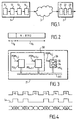
- FIG. 1 an example of a digital transmission system has been represented according to the invention between a transmitter 1 and a receiver 2 via a transmission medium 3.
- the transmitter 1 includes a data source 11, a source encoder 12, a channel encoder 13, and a digital modulator 14.
- the receiver 2 includes a digital demodulator 21, a channel decoder 22, and a source decoder 23.
- the transmission medium 3 can be different natures, for example, it can be a cable network, a satellite channel or a radio channel.
- the modulation used is chosen according to the transmission medium for take into account the characteristics of the transmission medium. In particular, we use single carrier modulations for cable and satellite transmissions, and multicarrier modulations for radio transmissions because the technique of multicarrier modulation offers good protection against the selectivity of radio channels, multi-path propagation and interference between radio channels.
- the multicarrier modulations used are OFDM modulations (from the English "Orthogonal Frequency Division Multiplexing").
- the OFDM technique consists in multiplexing in frequency N orthogonal carriers which are modulated by points of a constellation (for example points of an MAQ constellation). Each transmitted symbol (called OFDM symbol) therefore corresponds to a block of N points, each point of the block modulating one of the N orthogonal carriers.
- FIG. 2 we have shown the structure of an example OFDM symbol such that defined in the draft DVB-T standard.
- Each symbol is composed of a guard interval Tg suM of a useful part Tu.
- the guard interval Tg is used to eliminate the interference between the symbols.
- the nature of a carrier (useful carrier, carrier of data or carrier of control information) is determined by its location in I OFDM symbol.
- the carriers of control information are mainly used for the channel synchronization and estimation. Some of the treatments to be performed on these carriers therefore take place at a frequency of the order of the symbol frequency. However the processing to be carried out on the carriers of useful data is all carried out at a frequency of the order of the sampling frequency.
- FIG. 3 there is shown a block diagram of the architecture of a digital demodulator 21 according to the invention.
- These calculation units PU i communicate with each other via an interconnection network INT.
- the digital receiver described here is a programmable receiver which can be programmed to be used for different types of modulation. That implies in particular that the symbol frequency is not known a priori.
- the architecture used is a static architecture, periodic moments of communication (t0, t1, ...) are provided for transfer data (D0, D1, ...) from one calculation unit to another (see Figure 4), regardless of the value of the symbol frequency. It may therefore happen that no data is only available when a communication must take place (for example at time t2).
- a validity indicator Iv is therefore associated with each communication interval to inform the unit of calculation which expects a data whether or not there is a data in this time interval Communication. For example at time t2, as no data is available the validity indicator has a zero value.
- the PU K calculation unit comprises a second module 32 and an interface module 34.
- the second module 32 is capable of processing second demodulation functions according to one or more programs 36 which are repeated at a second frequency.
- An exemplary embodiment of an interface module 34 is shown in detail in FIG. 5. It includes selection means 40 for selecting data to be transmitted, a FIFO memory 42 for storing the data to be transmitted to the second module 32, a FIFO memory 44 for storing results provided by the second module, and transmission means 46 for transmitting to the first module 30 the results stored in memory 44.
- This interface module 34 is controlled by PGM programs K, j in particular by a PGM K, 1 writing program and by a PGM K, 2 reading program.
- the data received by the calculation unit PU K are either symbols containing N carriers, or any data which must be transmitted as such to the second module 32.
- the selection means 40 are used when the data received is a symbol, for select, in this symbol, the carriers to be transmitted to the second module 32 (only the carriers of control information must be transmitted).
- the selection means 40 are controlled by the writing program PGM K, 1 . They include a counter 50 and a table 52.
- the counter 50 numbers, in their order of appearance, the carriers contained in the symbol.
- Table 52 contains for each carrier number a transfer identifier It which indicates whether or not the corresponding carrier must be transmitted to the second module 32, that is to say whether it must be copied into the FIFO memory 42.
- FIFO memory 42 contains on the one hand the data to be transmitted to the second module 32, and on the other hand for each data item a function identifier If indicating the function source and / or destination function of the data. This If function identifier allows the second module 32 of knowing where to store the corresponding data for its processing ulterior.
- the second module 32 performs one or more functions which provide results. These results are stored in FIFO memory 44, with a function identifier If which indicates the source function and / or the destination function of the result. This identifier of If function makes it possible to manage, with the transmission means 46, the instant of communication to which a result must be transmitted to the first module 30.
- the transmission means 46 are controlled by the reading program PGM K, 2 .
- the program PGM K, 2 includes instructions which indicate the type of communication which must take place at the time of communication considered. Each type of communication corresponds to the transmission of a result of a certain type. The type of a result is indicated by the function identifier If associated with it.
- the transmission means 46 consist of a correspondence table which indicates the correspondence between a type of communication and the type or types of results to be transmitted. For example, there can be two different types of communications C 1 and C 2 , a communication of type C 1 corresponding to the transmission of a result whose function identifier If is equal to Z1 or to Z2, and a communication of type C 2 corresponding to the transmission of a result whose function identifier is equal to Z3.
- the reading program PGM K, 2 consults the correspondence table to determine whether the function identifier of the output result of the FIFO memory 44 corresponds to the type of communication. In this case the output result from the FIFO memory is transferred to the first module, with a validity identifier Iv equal to one. And the reading program goes to the next datum. Otherwise, the output result is not transferred (which means that it remains in the FIFO memory) and the validity indicator Iv associated with the current communication instant is set to zero.
- This mechanism makes it possible to guarantee that the results are transmitted in instants of communication that are correct in relation to the needs of the first module 30.
- FIG. 7 shows an example of a demodulator according to the invention for single-carrier modulations.
- This demodulator comprises a first module 30, a second module 32 and an interface module 34.
- the first module 30 essentially comprises a calculation unit PU 10 which transposes the received signal into baseband, a calculation unit PU 20 which performs the processing operations relating to synchronization, a PU 30 calculation unit which performs filtering operations for the recovery of symbols, and a PU 40 decoding unit.
- the interface module 34 and the second module 32 are grouped together in a calculation unit PU 7 .
- the PU 7 calculation unit is not used. All of the demodulation functions are processed by the first module 30.
- the programs which manage the operation of the calculation units PU 10 , PU 20 , PU 30 and PU 40 are repeated at a frequency of the order of the symbol frequency.
- a programmable digital demodulator has been described, usable for different types of modulations.
- the invention is not limited to this example. She is in particular applicable to an OFDM demodulator working at a predetermined symbol frequency, and in which communications (including the communication times at which the data must be transmitted) are easier to manage than in the example which has been described. It's clear that in this case the interface module can be simplified compared to that which has been described.
Landscapes
- Engineering & Computer Science (AREA)
- Computer Networks & Wireless Communication (AREA)
- Signal Processing (AREA)
- Digital Transmission Methods That Use Modulated Carrier Waves (AREA)
- Communication Control (AREA)
- Circuits Of Receivers In General (AREA)
Abstract
Description
L'invention concerne un système de transmission comportant au moins un émetteur et un récepteur, ledit récepteur comportant un démodulateur numérique de données. L'invention concerne également un récepteur et un démodulateur destinés à être utilisés dans un tel système.The invention relates to a transmission system comprising at least one transmitter and a receiver, said receiver comprising a digital data demodulator. The invention also relates to a receiver and a demodulator intended for use in such a system.
L'invention a d'importantes applications dans le domaine des modulations numériques.The invention has important applications in the field of digital modulations.
Le projet de norme DVB-T (de l'anglais Digital Video Broadcasting for Terrestrial) défini par l'ETSI et relatif à la diffusion de programmes de télévision numériques par liaisons hertziennes décrit un exemple d'un tel système de transmission. Notamment, ce projet prévoit l'utilisation de modulations multiporteuses, qui permettent d'utiliser au mieux les caractéristiques du canal de transmission.The draft DVB-T standard (from English Digital Video Broadcasting for Terrestrial) defined by ETSI and relating to the broadcasting of digital television programs by links hertziennes describes an example of such a transmission system. In particular, this project provides the use of multicarrier modulations, which allow the best use of the characteristics of the transmission channel.
Or l'utilisation de modulations multiporteuses pose un problème particulier. En effet, la technique de transmission mutliporteuses consiste à multiplexer en fréquence N porteuses qui sont modulées par des points d'une constellation (par exemple des points d'une constellation MAQ). Chaque symbole transmis (appelé symbole FDM de l'anglais "Frequency Division Multiplexing") correspond donc à un bloc de N points, chaque point du bloc modulant l'une des N porteuses. Dans le cas de transmissions multiporteuses, la fréquence d'échantillonnage du signal transmis est donc très supérieure à la fréquence des symboles FDM. Au niveau du démodulateur, certaines fonctions de démodulation s'effectuent à une fréquence de l'ordre de la fréquence d'échantillonnage des données reçues, tandis que d'autres s'effectuent à une fréquence de l'ordre de la fréquence symbole.The use of multicarrier modulations poses a particular problem. Indeed, the multi-carrier transmission technique consists in multiplexing in frequency N carriers which are modulated by points of a constellation (for example points of a constellation MAQ). Each symbol transmitted (called the FDM symbol in English "Frequency Division Multiplexing ") therefore corresponds to a block of N points, each point of the block modulating one of the N carriers. In the case of multi-carrier transmissions, the sampling frequency of the transmitted signal is therefore much higher than the frequency of FDM symbols. The level of demodulator, certain demodulation functions are performed at a frequency of the order of frequency of sampling of data received, while others are carried out at a frequency of the order of the symbol frequency.
Par ailleurs, il est souhaitable d'utiliser un modèle de communication statique pour gérer les échanges de données à l'intérieur d'un tel démodulateur. Utiliser un modèle de communication statique consiste à réaliser des fonctions déterminées, à des instants déterminés, en exécutant des programmes qui se répètent à une même fréquence, de façon à pouvoir fournir des données à un rythme régulier. Ce type de modèle de communication est avantageux car il permet de garantir que toutes les données sont transmises correctement et donc que les fonctions sont exécutées correctement.In addition, it is desirable to use a static communication model to manage data exchanges inside such a demodulator. Use a template static communication consists in carrying out specific functions, at times determined, by running programs that repeat themselves at the same frequency, so that ability to provide data at a regular rate. This type of communication model is advantageous because it ensures that all data is transmitted correctly and therefore that the functions are executed correctly.
Lorsque l'architecture d'un démodulateur pour modulations multiporteuses est une architecture statique, on est donc amené à choisir comme fréquence de répétition commune la fréquence la plus faible parmi les fréquences susceptibles d'être utilisées, c'est-à-dire une fréquence qui est de l'ordre de la fréquence symbole. Cela implique de mémoriser un très grand nombre d'instructions. En particulier les instructions relatives au traitement des différentes porteuses devront être mémorisées autant de fois qu'il y a de porteuses. Cette solution est extrêmement coûteuse en mémoire.When the architecture of a demodulator for multicarrier modulations is a static architecture, we are therefore led to choose as the common repetition frequency the lowest frequency among the frequencies likely to be used, i.e. a frequency which is of the order of the symbol frequency. This involves memorizing a very large number of instructions. In particular the instructions relating to the treatment of the different carriers must be memorized as many times as there are carriers. This solution is extremely expensive in memory.
L'invention a pour but de proposer un démodulateur qui apporte une solution à ce problème. The object of the invention is to propose a demodulator which provides a solution to this problem.
Ce but est atteint avec un système de transmission, un récepteur et un démodulateur tels que décrits dans les paragraphes introductifs, et caractérisés en ce que ledit démodulateur comporte:
- un premier module dédié au traitement de premières fonctions de démodulation conformément à au moins un premier programme qui se répète à une première fréquence,
- un second module susceptible d'être dédié au traitement de secondes fonctions de démodulation conformément à au moins un second programme qui se répète à une seconde fréquence,
- et un module d'interface pour échanger des données entre lesdits modules.
- a first module dedicated to the processing of first demodulation functions in accordance with at least one first program which repeats at a first frequency,
- a second module capable of being dedicated to the processing of second demodulation functions in accordance with at least one second program which repeats at a second frequency,
- and an interface module for exchanging data between said modules.
L'invention consiste donc à séparer l'architecture du démodulateur en deux parties communiquant par l'intermédiaire d'une interface. Dans le cas de modulations multiporteuses, l'une de ces parties (le premier module) est dédiée au traitement des fonctions qui doivent s'effectuer à une fréquence de l'ordre de la fréquence d'échantillonnage. L'autre partie (le second module) est dédiée au traitement des fonctions qui doivent s'effectuer à une fréquence de l'ordre de la fréquence symbole. Les programmes de fonctionnement du premier module ont une fréquence de répétition de l'ordre de la fréquence d'échantillonnage. En conséquence, les instructions relatives au traitement des différentes porteuses ne sont mémorisées qu'un nombre minimum de fois. La taille mémoire nécessaire pour le stockage desdits programmes est donc réduite à une taille minimum.The invention therefore consists in separating the architecture of the demodulator into two parts communicating through an interface. In the case of multicarrier modulations, one of these parts (the first module) is dedicated to the processing of functions which must take place at a frequency on the order of the sampling frequency. The other part (the second module) is dedicated to the processing of functions which must be performed at a frequency of the order of the symbol frequency. The operating programs of the first module have a repetition frequency of the order of the sampling frequency. Consequently, instructions relating to the processing of the different carriers are only stored a number minimum of times. The memory size required for storing said programs is therefore reduced to a minimum size.
L'invention présente en plus l'avantage de fournir une architecture qui est utilisable pour des systèmes de transmission qui utilisent des modulations monoporteuses, par exemple pour des systèmes de transmission par câble ou par satellite. Dans ce type de système la fréquence d'échantillonnage et la fréquence symbole sont du même ordre de grandeur de telle sorte que le problème évoqué ci-dessus ne se pose pas. Dans ce cas, seul l'un des modules est utilisé (le premier module). Et les programmes de fonctionnement de ce module ont une fréquence de répétition de l'ordre de la fréquence symbole.The invention also has the advantage of providing an architecture which can be used for transmission systems which use single carrier modulations, for example for cable or satellite transmission systems. In this type of system the frequency sampling frequency and symbol frequency are of the same order of magnitude so that the problem mentioned above does not arise. In this case, only one of the modules is used (the first module). And the operating programs of this module have a frequency of repetition of the order of the symbol frequency.
L'invention sera mieux comprise et d'autres détails apparaítront dans la description qui va suivre en regard des dessins annexés qui sont donnés à titre d'exemple non limitatif et dans lesquels:
- la figure 1 représente un exemple de système de transmission selon l'invention,
- la figure 2 représente la structure d'un symbole FDM,
- la figure 3 est un schéma de l'architecture d'un démodulateur numérique selon l'invention,
- la figure 4 est un schéma explicatif de la gestion des communications internes dans un démodulateur tel que représenté sur la figure 3,
- la figure 5 est un schéma d'un exemple de module d'interface d'un démodulateur selon l'invention,
- la figure 6 est un schéma d'un démodulateur OFDM selon l'invention
- la figure 7 est un schéma d'un démodulateur selon l'invention pour les modulations monoporteuses utilisées dans les systèmes de diffusion de programmes numériques par câble ou par satellite définis par les projets de normes DVB.
- FIG. 1 represents an example of a transmission system according to the invention,
- FIG. 2 represents the structure of an FDM symbol,
- FIG. 3 is a diagram of the architecture of a digital demodulator according to the invention,
- FIG. 4 is an explanatory diagram of the management of internal communications in a demodulator as shown in FIG. 3,
- FIG. 5 is a diagram of an example of an interface module of a demodulator according to the invention,
- FIG. 6 is a diagram of an OFDM demodulator according to the invention
- FIG. 7 is a diagram of a demodulator according to the invention for the single-carrier modulations used in systems for broadcasting digital programs by cable or satellite defined by the draft DVB standards.
Sur la figure 1 on a representé un exemple de système de transmission numérique selon
l'invention entre un émetteur 1 et un récepteur 2 via un média de transmission 3. L'émetteur 1
comporte une source de données 11, un codeur de source 12, un codeur de canal 13, et un
modulateur numérique 14. Le récepteur 2 comporte un démodulateur numérique 21, un
décodeur de canal 22, et un décodeur de source 23. Le média de transmission 3 peut être de
différentes natures, par exemple, il peut s'agir d'un réseau câblé, d'un canal satellite ou d'un
canal hertzien. La modulation utilisée est choisie en fonction du média de transmission pour
tenir compte au mieux des caractéristiques du média de transmission. En particulier, on utilise
des modulations monoporteuses pour les transmissions par câble et par satellite, et des
modulations multiporteuses pour les transmissions hertziennes parce que la technique de
modulation multiporteuses offre une bonne protection contre la sélectivité des canaux hertziens,
la propagation multi-chemins et les interférences entre canaux hertziens.In FIG. 1, an example of a digital transmission system has been represented according to
the invention between a
Dans le cas du projet de norme DVB-T défini par l'ETSI, les modulations multiporteuses utilisées sont des modulations OFDM (de l'anglais "Orthogonal Frequency Division Multiplexing"). La technique OFDM consiste à multiplexer en fréquence N porteuses orthogonales qui sont modulées par des points d'une constellation (par exemple des points d'une constellation MAQ). Chaque symbole transmis (appelé symbole OFDM) correspond donc à un bloc de N points, chaque point du bloc modulant l'une des N porteuses orthogonales.In the case of the draft DVB-T standard defined by ETSI, the multicarrier modulations used are OFDM modulations (from the English "Orthogonal Frequency Division Multiplexing"). The OFDM technique consists in multiplexing in frequency N orthogonal carriers which are modulated by points of a constellation (for example points of an MAQ constellation). Each transmitted symbol (called OFDM symbol) therefore corresponds to a block of N points, each point of the block modulating one of the N orthogonal carriers.
Sur la figure 2 on a representé la structure d'un exemple de symbole OFDM tel que défini dans le projet de norme DVB-T. Chaque symbole est composé d'un intervalle de garde Tg suM d'une partie utile Tu. L'intervalle de garde Tg sert à éliminer l'interférence entre les symboles. La partie utile contient N=8192 échantillons. Ces 8192 échantillons correspondent à 6817 porteuses utiles. Et parmi ces 6817 porteuses utiles, certaines véhiculent des données et d'autres des informations de contrôle. La nature d'une porteuse (porteuse utile, porteuse de données ou porteuse d'informations de contrôle) est déterminée par son emplacement dans Je symbole OFDM. Les porteuses d'informations de contrôle sont essentiellement utilisées pour la synchronisation et l'estimation de canal. Certains des traitements à effectuer sur ces porteuses s'effectuent donc à une fréquence de l'ordre de la fréquence symbole. En revanche les traitements à effectuer sur les porteuses de données utiles s'effectuent tous à une fréquence de l'ordre de la fréquence d'échantillonnage.In Figure 2 we have shown the structure of an example OFDM symbol such that defined in the draft DVB-T standard. Each symbol is composed of a guard interval Tg suM of a useful part Tu. The guard interval Tg is used to eliminate the interference between the symbols. The useful part contains N = 8192 samples. These 8192 samples correspond to 6817 useful carriers. And among these 6817 useful carriers, some carry data and others control information. The nature of a carrier (useful carrier, carrier of data or carrier of control information) is determined by its location in I OFDM symbol. The carriers of control information are mainly used for the channel synchronization and estimation. Some of the treatments to be performed on these carriers therefore take place at a frequency of the order of the symbol frequency. However the processing to be carried out on the carriers of useful data is all carried out at a frequency of the order of the sampling frequency.
Sur la figure 3 on a representé un schéma de principe de l'architecture d'un
démodulateur numérique 21 selon l'invention. Le démodulateur 21 comporte une pluralité
d'unité de calcul PU1 (i=1, ..., K) commandées par des programmes PGMi,j (j=1,...,Li) qui se
répètent à une première fréquence. Ces unités de calcul PUi communiquent entre elles par
l'intermédiaire d'un réseau d'interconnexion INT. In Figure 3 there is shown a block diagram of the architecture of a
Le démodulateur numérique décrit ici est un démodulateur programmable qui peut être programmé de façon à être utilisé pour différents types de modulations. Cela implique notamment que la fréquence symbole n'est pas connue à priori. L'architecture utilisée étant une architecture statique, des instants périodiques de communication (t0, t1, ...) sont prévus pour transférer des données (D0, D1,...) d'une unité de calcul à une autre (voir figure 4), indépendamment de la valeur de la fréquence symbole. Il peut donc arriver qu'aucune donnée ne soit disponible alors qu'une communication doit avoir lieu (par exemple à l'instant t2). Un indicateur de validité Iv est donc associé à chaque intervalle de communication pour informer l'unité de calcul qui attend une donnée s'il y a ou non une donnée dans cet intervalle de temps de communication. Par exemple à l'instant t2, comme aucune donnée n'est disponible l'indicateur de validité a une valeur nulle.The digital receiver described here is a programmable receiver which can be programmed to be used for different types of modulation. That implies in particular that the symbol frequency is not known a priori. The architecture used is a static architecture, periodic moments of communication (t0, t1, ...) are provided for transfer data (D0, D1, ...) from one calculation unit to another (see Figure 4), regardless of the value of the symbol frequency. It may therefore happen that no data is only available when a communication must take place (for example at time t2). A validity indicator Iv is therefore associated with each communication interval to inform the unit of calculation which expects a data whether or not there is a data in this time interval Communication. For example at time t2, as no data is available the validity indicator has a zero value.
Les unités de calcul PUi(i=1,...,K-1) constituent un premier module 30. Elles traitent des
premières fonctions de démodulation conformément aux programmes PGMi,j qui se répètent à
une première fréquence. L'unité de calcul PUK comporte un second module 32 et un module
d'interface 34. Le second module 32 est susceptible de traiter des secondes fonctions de
démodulation selon un ou plusieurs programmes 36 qui se répètent à une seconde fréquence.The calculation units PU i (i = 1, ..., K-1) constitute a
Un exemple de réalisation d'un module d'interface 34 est représenté en détails sur la
figure 5. Il comporte des moyens de sélection 40 pour sélectionner des données à transmettre,
une mémoire FIFO 42 pour mémoriser les données à transmettre au second module 32, une
mémoire FIFO 44 pour mémoriser des résultats fournis par le second module, et des moyens 46
de transmission pour transmettre au premier module 30 les résultats stockés dans la mémoire
44. Ce module d'interface 34 est contrôlé par des programmes PGMK,j notamment par un
programme d'écriture PGMK,1 et par un programme de lecture PGMK,2.An exemplary embodiment of an
Les données reçues par l'unité de calcul PUK sont soit des symboles contenant N
porteuses, soit des données quelconques qui doivent être transmises telles quelles au second
module 32. Les moyens de sélection 40 sont utilisés lorsque la donnée reçue est un symbole,
pour sélectionner, dans ce symbole, les porteuses à transmettre au second module 32 (seules
les porteuses d'informations de contrôle doivent être transmises). Les moyens de sélection 40
sont commandés par le programme d'écriture PGMK,1. Ils comportent un compteur 50 et une
table 52. Le compteur 50 numérote, dans leur ordre d'apparition, les porteuses contenues dans
le symbole. La table 52 contient pour chaque numéro de porteuse un identificateur de transfert
It qui indique si la porteuse correspondante doit ou non être transmise au second module 32,
c'est-à-dire si elle doit être copiée dans la mémoire FIFO 42.The data received by the calculation unit PU K are either symbols containing N carriers, or any data which must be transmitted as such to the
Les données autres que les symboles, susceptibles d'être transmises du premier module
30 vers le second module 32, sont copiées directement dans la mémoire FIFO 42.Data other than symbols, which can be transmitted from the
La mémoire FIFO 42 contient d'une part les données à transmettre au second module
32, et d'autre part pour chaque donnée un identificateur de fonction If indiquant la fonction
source et / ou la fonction destination de la donnée. Cet identificateur de fonction If permet au
second module 32 de savoir où mémoriser la donnée correspondante pour son traitement
ultérieur.
Le second module 32 exécute une ou plusieurs fonctions qui fournissent des résultats.
Ces résultats sont stockés dans la mémoire FIFO 44, avec un identificateur de fonction If qui
indique la fonction source et / ou la fonction destination du résultat. Cet identificateur de
fonction If permet de gérer, avec les moyens de transmission 46, l'instant de communication
auquel un résultat doit être transmis au premier module 30.The
Les moyens de transmission 46 sont contrôlés par le programme de lecture PGMK,2. Le
programme PGMK,2 comporte des instructions qui indiquent le type de communication qui doit
avoir lieu à l'instant de communication considéré. Chaque type de communication correspond à
la transmission d'un résultat d'un certain type. Le type d'un résultat est indiqué par
l'identificateur de fonction If qui lui est associé. Les moyens de transmission 46 sont constitués
par une table de correspondance qui indique la correspondance entre un type de communication
et le ou les types de résultats à transmettre. Par exemple on peut avoir deux types de
communications différentes C1 et C2, une communication de type C1 correspondant à la
transmission d'un résultat dont l'identificateur de fonction If est égal à Z1 ou à Z2, et une
communication de type C2 correspondant à la transmission d'un résultat dont l'identificateur de
fonction est égale à Z3. Pour chaque instant de communication le programme de lecture PGMK,2
consulte la table de correspondance pour déterminer si l'identificateur de fonction du résultat de
sortie de la mémoire FIFO 44 correspond au type de la communication. Dans ce cas le résultat
de sortie de la mémoire FIFO est transféré vers le premier module, avec un identificateur de
validité Iv égal à un. Et le programme de lecture passe à la donnée suivante. Dans le cas
contraire, le résultat de sortie n'est pas transféré (ce qui signifie qu'il reste dans la mémoire
FIFO) et l'indicateur de validité Iv associé à l'instant de communication courant est positionné à
zéro. Ce mécanisme permet de garantir que les résultats sont transmis dans des instants de
communication corrects par rapport aux besoins du premier module 30.The transmission means 46 are controlled by the reading program PGM K, 2 . The program PGM K, 2 includes instructions which indicate the type of communication which must take place at the time of communication considered. Each type of communication corresponds to the transmission of a result of a certain type. The type of a result is indicated by the function identifier If associated with it. The transmission means 46 consist of a correspondence table which indicates the correspondence between a type of communication and the type or types of results to be transmitted. For example, there can be two different types of communications C 1 and C 2 , a communication of type C 1 corresponding to the transmission of a result whose function identifier If is equal to Z1 or to Z2, and a communication of type C 2 corresponding to the transmission of a result whose function identifier is equal to Z3. For each instant of communication, the reading program PGM K, 2 consults the correspondence table to determine whether the function identifier of the output result of the
La figure 6 représente un exemple de démodulateur OFDM selon l'invention. Dans ce cas, les unités de calcul du premier module 30 traitent les fonctions de démodulation qui s'effectuent à une fréquence de l'ordre de la fréquence d'échantillonnage. Elles sont commandées par des programmes PGMi,j qui se répètent à une fréquence de l'ordre de la fréquence d'échantillonnage. Ces unités de calcul sont essentiellement constituées par une unité de calcul PU1 qui transpose le signal reçu en bande de base, une unité de calcul PU2 qui effectue les traitement relatifs à la synchronisation, une unité de calcul PU3 qui effectue essentiellement l'opération de transformée de Fourier inverse pour la récupération des symboles, une unité de calcul PU4 chargée de la correction de canal, une unité PU5 qui est une mémoire de délai servant à stocker un symbole pendant l'opération de correction de canal, et une unité PU6 de décodage. Le module d'interface 34 et le second module 32 sont regroupés dans une unité de calcul PU7. Le second module 32 traitent les fonctions de démodulation qui s'effectuent à une fréquence de l'ordre de la fréquence symbole. Il est commandé par les programmes 36 qui se répètent à une fréquence de l'ordre de la fréquence symbole. Les échanges entre le premier module 30 et le second module 32 s'effectuent par exemple de la façon suivante:
- l'unité PU3 transmet des symboles à l'unité PU7,
- l'unité PU7 transmet à l'unité PU2 des résultats relatifs à la synchronisation,
- l'unité PU7 transmet à l'unité PU4 des résultats relatifs à la correction de canal.
- the PU 3 unit transmits symbols to the PU 7 unit,
- the PU unit 7 transmits synchronization results to the PU unit 2 ,
- the PU unit 7 transmits results relating to the channel correction to the PU unit 4 .
Sur la figure 7 on a représenté un exemple de démodulateur selon l'invention pour
modulations monoporteuses. Ce démodulateur comporte un premier module 30, un second
module 32 et un module d'interface 34. Le premier module 30 comporte essentiellement une
unité de calcul PU10 qui transpose le signal reçu en bande de base, une unité de calcul PU20 qui
effectue les traitements relatifs à la synchronisation, une unité de calcul PU30 qui effectue des
opérations de filtrage pour la récupération des symboles, et une unité PU40 de décodage. Le
module d'interface 34 et le second module 32 sont regroupés dans une unité de calcul PU7.
L'unité de calcul PU7 n'est pas utilisée. Toutes les fonctions de démodulation sont traitées par le
premier module 30. Les programmes qui gèrent le fonctionnement des unités de calcul PU10,
PU20, PU30 et PU40 se répètent à une fréquence de l'ordre de la fréquence symbole.FIG. 7 shows an example of a demodulator according to the invention for single-carrier modulations. This demodulator comprises a
On a décrit un démodulateur numérique programmable, utilisable pour différents types de modulations. Mais l'invention n'est pas restreinte à cet exemple. Elle est en particulier applicable à un démodulateur OFDM travaillant à une fréquence symbole prédéterminée, et dans lequel les communications (notamment les instants de communication auxquels les données doivent être transmises) sont plus simples à gérer que dans l'exemple qui a été décrit. Il est clair que dans ce cas le module d'interface peut être simplifié par rapport à celui qui a été décrit.A programmable digital demodulator has been described, usable for different types of modulations. However, the invention is not limited to this example. She is in particular applicable to an OFDM demodulator working at a predetermined symbol frequency, and in which communications (including the communication times at which the data must be transmitted) are easier to manage than in the example which has been described. It's clear that in this case the interface module can be simplified compared to that which has been described.
De même, si toutes les données transmises du premier module 30 vers le second
module 32 sont issues de la même unité de calcul, par exemple si les seules données transmises
sont les symboles issus de l'unité chargée des calculs de transformée de Fourier, il est inutile de
mémoriser dans la mémoire FIFO 42 un identificateur de fonction indiquant la fonction source et
/ ou destination de la donnée.Similarly, if all the data transmitted from the
Claims (10)
Applications Claiming Priority (2)
| Application Number | Priority Date | Filing Date | Title |
|---|---|---|---|
| FR9906018 | 1999-05-11 | ||
| FR9906018 | 1999-05-11 |
Publications (2)
| Publication Number | Publication Date |
|---|---|
| EP1052822A1 true EP1052822A1 (en) | 2000-11-15 |
| EP1052822B1 EP1052822B1 (en) | 2009-11-11 |
Family
ID=9545484
Family Applications (1)
| Application Number | Title | Priority Date | Filing Date |
|---|---|---|---|
| EP00201577A Expired - Lifetime EP1052822B1 (en) | 1999-05-11 | 2000-05-02 | Programmable OFDM digital demodulator |
Country Status (4)
| Country | Link |
|---|---|
| US (1) | US6754281B1 (en) |
| EP (1) | EP1052822B1 (en) |
| JP (1) | JP2000341245A (en) |
| DE (1) | DE60043275D1 (en) |
Families Citing this family (5)
| Publication number | Priority date | Publication date | Assignee | Title |
|---|---|---|---|---|
| US20050251844A1 (en) * | 2001-02-02 | 2005-11-10 | Massimiliano Martone | Blind correlation for high precision ranging of coded OFDM signals |
| AU2002251852A1 (en) * | 2001-02-02 | 2002-08-19 | Rosum Corporation | Services based on position location using broadcast digital television signals |
| WO2009149104A2 (en) | 2008-06-03 | 2009-12-10 | Rosum Corporation | Time, frequency, and location determination for femtocells |
| US20020184653A1 (en) | 2001-02-02 | 2002-12-05 | Pierce Matthew D. | Services based on position location using broadcast digital television signals |
| CN102112972B (en) * | 2008-08-07 | 2014-05-07 | 日本电气株式会社 | Multiprocessor system and method for controlling same |
Citations (2)
| Publication number | Priority date | Publication date | Assignee | Title |
|---|---|---|---|---|
| EP0340978A2 (en) * | 1988-05-02 | 1989-11-08 | International Standard Electric Corporation | Modulator/demodulator apparatus |
| EP0353890A2 (en) * | 1988-08-02 | 1990-02-07 | International Business Machines Corporation | Information handling centre telecommunication servers |
Family Cites Families (3)
| Publication number | Priority date | Publication date | Assignee | Title |
|---|---|---|---|---|
| US4709344A (en) * | 1985-10-02 | 1987-11-24 | Motorola, Inc. | Programmable multifrequency digital tone receiver |
| MY116925A (en) * | 1996-07-08 | 2004-04-30 | Kenwood Corp | Apparatus for demodulating am data multiplexed modulated wave signal |
| US5995483A (en) * | 1996-08-22 | 1999-11-30 | Tellabs Operations, Inc. | Apparatus and method for upstream clock synchronization in a multi-point OFDM/DMT digital communication system |
-
2000
- 2000-05-02 DE DE60043275T patent/DE60043275D1/en not_active Expired - Lifetime
- 2000-05-02 EP EP00201577A patent/EP1052822B1/en not_active Expired - Lifetime
- 2000-05-08 JP JP2000134365A patent/JP2000341245A/en active Pending
- 2000-05-10 US US09/568,287 patent/US6754281B1/en not_active Expired - Lifetime
Patent Citations (2)
| Publication number | Priority date | Publication date | Assignee | Title |
|---|---|---|---|---|
| EP0340978A2 (en) * | 1988-05-02 | 1989-11-08 | International Standard Electric Corporation | Modulator/demodulator apparatus |
| EP0353890A2 (en) * | 1988-08-02 | 1990-02-07 | International Business Machines Corporation | Information handling centre telecommunication servers |
Also Published As
| Publication number | Publication date |
|---|---|
| EP1052822B1 (en) | 2009-11-11 |
| JP2000341245A (en) | 2000-12-08 |
| DE60043275D1 (en) | 2009-12-24 |
| US6754281B1 (en) | 2004-06-22 |
Similar Documents
| Publication | Publication Date | Title |
|---|---|---|
| EP2499796A1 (en) | Method for transmitting pre-equalized digital data, and transmitting base implementing such a method | |
| FR2658016A1 (en) | METHOD FOR DIFFUSION OF DIGITAL DATA, IN PARTICULAR FOR HIGH-SPEED MOVING BROADCASTING AT MOBILE, TIME-FREQUENCY INTERLACING, AND COHERENT DEMODULATION, AND CORRESPONDING RECEIVER | |
| FR2758031A1 (en) | METHOD AND APPARATUS FOR SYNCHRONIZING FRAMES FOR USE IN A DIGITAL COMMUNICATION SYSTEM USING AN ORTHOGONAL FREQUENCY DISTRIBUTION MULTIPLEXING METHOD | |
| FR2732178A1 (en) | DIGITAL TRANSMISSION SYSTEM WITH CASCADE EQUALIZER RECEIVER | |
| WO2007048790A1 (en) | Method for transmitting a multi-carrier signal designed for limiting interference, signal, emitting device, receiving method and device, and corresponding computer programs | |
| EP2039095B1 (en) | Methods for transmitting and receiving a multicarrier signal, carrying out a channel estimation, and corresponding devices and computer program products | |
| FR2885470A1 (en) | METHOD FOR ENCODING AN OFDM / OQAM-TYPE MULTIPORTING SIGNAL USING SYMBOLS WITH COMPLEX VALUES, SIGNAL, COMPUTER DEVICES AND COMPUTER PROGRAMS | |
| EP3391605B1 (en) | Faster than nyquist ofdm/oqam induced interference precompensation | |
| WO2016207555A1 (en) | Multiple stream transmission method comprising multicarrier modulation selection according to the associated communication type | |
| EP2904754A1 (en) | Method for the transmission of a multi-carrier signal, and corresponding transmission device and computer program | |
| WO2008007019A2 (en) | Methods for the transmission and reception of a multicarrier signal with oqam modulation, and specific preamble | |
| EP1052822B1 (en) | Programmable OFDM digital demodulator | |
| FR2825551A1 (en) | METHOD OF ESTIMATING THE FUNCTION OF TRANSFERRING A TRANSMISSION CHANNEL OF A MULTI-CARRIER SIGNAL, METHOD OF RECEIVING A DIGITAL SIGNAL, AND RECEIVER OF A MULTI-CARRIER SIGNAL CORRESPONDING | |
| FR2903833A1 (en) | Signal receiving method for e.g. wireless telephone, involves estimating real and imaginary parts of transmission channel in neighboring region from complex values corresponding to drivers of group of region | |
| EP2039102B1 (en) | Methods for receiving and transmitting a multicarrier signal comprising a preamble containing data elements, corresponding devices and computer program products | |
| WO2006117268A1 (en) | Method for the iterative decoding of an ofdm/oqam signal using symbols with complex values, and corresponding device and computer program | |
| WO2008007020A2 (en) | Methods for the transmission and reception of a multicarrier signal comprising isolated pilots, and corresponding devices and computer program products | |
| EP1733577B8 (en) | Cellular radiotelephone signal which enables synchronisation at a frame of a supplementary channel by means of symbol numbering | |
| EP1034645A1 (en) | Method for estimating an interference phase shift when receiving a multicarrier signal and corresponding receiver | |
| EP0731588B1 (en) | Multiresolution phase modulation, for multicarrier systems | |
| EP4364333A1 (en) | Method for cooperative retransmission in an omamrc system | |
| FR3006132B1 (en) | DEMODULATION METHOD AND DEMODULATOR OF A CONTINUOUS PHASE MODULE SIGNAL, AND CORRESPONDING COMPUTER PROGRAM | |
| FR2799596A1 (en) | Equipment for optimising a multicarrier modulation transmission system, comprises one multicarrier modulator which favors a minimum error rate and a second which favors maximum information flow | |
| FR3004040A1 (en) | METHOD FOR TRANSMITTING A MULTI-CARRIER SIGNAL, TRANSMITTING DEVICE AND CORRESPONDING COMPUTER PROGRAM | |
| FR2996711A1 (en) | Method for multicarrier transmission of orthogonal frequency division multiplexing signal, involves accumulating corrected time samples with stored set of previously corrected time samples associated with preceding carrier |
Legal Events
| Date | Code | Title | Description |
|---|---|---|---|
| PUAI | Public reference made under article 153(3) epc to a published international application that has entered the european phase |
Free format text: ORIGINAL CODE: 0009012 |
|
| AK | Designated contracting states |
Kind code of ref document: A1 Designated state(s): DE ES FR GB IT |
|
| AX | Request for extension of the european patent |
Free format text: AL;LT;LV;MK;RO;SI |
|
| 17P | Request for examination filed |
Effective date: 20010515 |
|
| AKX | Designation fees paid |
Free format text: DE ES FR GB IT |
|
| 17Q | First examination report despatched |
Effective date: 20041108 |
|
| RAP1 | Party data changed (applicant data changed or rights of an application transferred) |
Owner name: NXP B.V. |
|
| GRAP | Despatch of communication of intention to grant a patent |
Free format text: ORIGINAL CODE: EPIDOSNIGR1 |
|
| GRAS | Grant fee paid |
Free format text: ORIGINAL CODE: EPIDOSNIGR3 |
|
| GRAA | (expected) grant |
Free format text: ORIGINAL CODE: 0009210 |
|
| AK | Designated contracting states |
Kind code of ref document: B1 Designated state(s): DE ES FR GB IT |
|
| REG | Reference to a national code |
Ref country code: GB Ref legal event code: FG4D Free format text: NOT ENGLISH |
|
| REF | Corresponds to: |
Ref document number: 60043275 Country of ref document: DE Date of ref document: 20091224 Kind code of ref document: P |
|
| PG25 | Lapsed in a contracting state [announced via postgrant information from national office to epo] |
Ref country code: ES Free format text: LAPSE BECAUSE OF FAILURE TO SUBMIT A TRANSLATION OF THE DESCRIPTION OR TO PAY THE FEE WITHIN THE PRESCRIBED TIME-LIMIT Effective date: 20100222 |
|
| PGFP | Annual fee paid to national office [announced via postgrant information from national office to epo] |
Ref country code: GB Payment date: 20100329 Year of fee payment: 11 |
|
| PGFP | Annual fee paid to national office [announced via postgrant information from national office to epo] |
Ref country code: FR Payment date: 20100525 Year of fee payment: 11 |
|
| PLBE | No opposition filed within time limit |
Free format text: ORIGINAL CODE: 0009261 |
|
| STAA | Information on the status of an ep patent application or granted ep patent |
Free format text: STATUS: NO OPPOSITION FILED WITHIN TIME LIMIT |
|
| 26N | No opposition filed |
Effective date: 20100812 |
|
| PG25 | Lapsed in a contracting state [announced via postgrant information from national office to epo] |
Ref country code: IT Free format text: LAPSE BECAUSE OF FAILURE TO SUBMIT A TRANSLATION OF THE DESCRIPTION OR TO PAY THE FEE WITHIN THE PRESCRIBED TIME-LIMIT Effective date: 20091111 |
|
| REG | Reference to a national code |
Ref country code: DE Ref legal event code: R082 Ref document number: 60043275 Country of ref document: DE Representative=s name: EPPING HERMANN FISCHER, PATENTANWALTSGESELLSCH, DE |
|
| GBPC | Gb: european patent ceased through non-payment of renewal fee |
Effective date: 20110502 |
|
| REG | Reference to a national code |
Ref country code: FR Ref legal event code: ST Effective date: 20120131 |
|
| PG25 | Lapsed in a contracting state [announced via postgrant information from national office to epo] |
Ref country code: FR Free format text: LAPSE BECAUSE OF NON-PAYMENT OF DUE FEES Effective date: 20110531 |
|
| REG | Reference to a national code |
Ref country code: FR Ref legal event code: TP Owner name: TRIDENT MICROSYSTEMS (FAR EAST) LTD., KY Effective date: 20120418 |
|
| PG25 | Lapsed in a contracting state [announced via postgrant information from national office to epo] |
Ref country code: GB Free format text: LAPSE BECAUSE OF NON-PAYMENT OF DUE FEES Effective date: 20110502 |
|
| REG | Reference to a national code |
Ref country code: DE Ref legal event code: R084 Ref document number: 60043275 Country of ref document: DE Effective date: 20110427 |
|
| REG | Reference to a national code |
Ref country code: DE Ref legal event code: R082 Ref document number: 60043275 Country of ref document: DE Representative=s name: EPPING HERMANN FISCHER, PATENTANWALTSGESELLSCH, DE |
|
| REG | Reference to a national code |
Ref country code: DE Ref legal event code: R081 Ref document number: 60043275 Country of ref document: DE Owner name: ENTROPIC COMMUNICATIONS, INC., US Free format text: FORMER OWNER: TRIDENT MICROSYSTEMS (FAR EAST) LTD., GRAND CAYMAN, KY Effective date: 20121023 Ref country code: DE Ref legal event code: R082 Ref document number: 60043275 Country of ref document: DE Representative=s name: EPPING HERMANN FISCHER, PATENTANWALTSGESELLSCH, DE Effective date: 20121023 Ref country code: DE Ref legal event code: R082 Ref document number: 60043275 Country of ref document: DE Representative=s name: EPPING HERMANN FISCHER, PATENTANWALTSGESELLSCH, DE Effective date: 20111017 Ref country code: DE Ref legal event code: R081 Ref document number: 60043275 Country of ref document: DE Owner name: ENTROPIC COMMUNICATIONS, INC., SAN DIEGO, US Free format text: FORMER OWNER: TRIDENT MICROSYSTEMS (FAR EAST) LTD., GRAND CAYMAN, KY Effective date: 20121023 |
|
| PGFP | Annual fee paid to national office [announced via postgrant information from national office to epo] |
Ref country code: DE Payment date: 20130530 Year of fee payment: 14 |
|
| REG | Reference to a national code |
Ref country code: DE Ref legal event code: R119 Ref document number: 60043275 Country of ref document: DE |
|
| REG | Reference to a national code |
Ref country code: DE Ref legal event code: R119 Ref document number: 60043275 Country of ref document: DE Effective date: 20141202 |
|
| PG25 | Lapsed in a contracting state [announced via postgrant information from national office to epo] |
Ref country code: DE Free format text: LAPSE BECAUSE OF NON-PAYMENT OF DUE FEES Effective date: 20141202 |