EP1049416B1 - Working device for drilling, cutting and screwdriver instruments used for medical purposes - Google Patents
Working device for drilling, cutting and screwdriver instruments used for medical purposes Download PDFInfo
- Publication number
- EP1049416B1 EP1049416B1 EP99924915A EP99924915A EP1049416B1 EP 1049416 B1 EP1049416 B1 EP 1049416B1 EP 99924915 A EP99924915 A EP 99924915A EP 99924915 A EP99924915 A EP 99924915A EP 1049416 B1 EP1049416 B1 EP 1049416B1
- Authority
- EP
- European Patent Office
- Prior art keywords
- drive device
- torque
- step motor
- current
- motor
- Prior art date
- Legal status (The legal status is an assumption and is not a legal conclusion. Google has not performed a legal analysis and makes no representation as to the accuracy of the status listed.)
- Expired - Lifetime
Links
- 238000005553 drilling Methods 0.000 title description 5
- 238000000034 method Methods 0.000 claims description 23
- 230000009467 reduction Effects 0.000 claims description 7
- 238000001228 spectrum Methods 0.000 claims description 5
- 230000033001 locomotion Effects 0.000 claims description 4
- 238000011282 treatment Methods 0.000 description 22
- 210000004262 dental pulp cavity Anatomy 0.000 description 17
- 230000001954 sterilising effect Effects 0.000 description 9
- 238000004659 sterilization and disinfection Methods 0.000 description 9
- 230000005540 biological transmission Effects 0.000 description 7
- 238000002474 experimental method Methods 0.000 description 7
- 210000003298 dental enamel Anatomy 0.000 description 6
- 238000012544 monitoring process Methods 0.000 description 6
- 238000002360 preparation method Methods 0.000 description 6
- 239000000463 material Substances 0.000 description 5
- 210000000988 bone and bone Anatomy 0.000 description 3
- 208000002925 dental caries Diseases 0.000 description 3
- 238000013519 translation Methods 0.000 description 3
- 238000010276 construction Methods 0.000 description 2
- 238000011161 development Methods 0.000 description 2
- 230000018109 developmental process Effects 0.000 description 2
- 230000000694 effects Effects 0.000 description 2
- 238000001356 surgical procedure Methods 0.000 description 2
- 208000006558 Dental Calculus Diseases 0.000 description 1
- 229910001200 Ferrotitanium Inorganic materials 0.000 description 1
- 206010044029 Tooth deposit Diseases 0.000 description 1
- 230000001133 acceleration Effects 0.000 description 1
- 230000015572 biosynthetic process Effects 0.000 description 1
- 230000001419 dependent effect Effects 0.000 description 1
- 238000001514 detection method Methods 0.000 description 1
- 230000006866 deterioration Effects 0.000 description 1
- 239000003814 drug Substances 0.000 description 1
- 208000014674 injury Diseases 0.000 description 1
- 238000009434 installation Methods 0.000 description 1
- 238000011835 investigation Methods 0.000 description 1
- 238000004643 material aging Methods 0.000 description 1
- 210000005036 nerve Anatomy 0.000 description 1
- 229910001000 nickel titanium Inorganic materials 0.000 description 1
- 230000035515 penetration Effects 0.000 description 1
- 238000003825 pressing Methods 0.000 description 1
- 239000010959 steel Substances 0.000 description 1
- 230000035882 stress Effects 0.000 description 1
- 230000008733 trauma Effects 0.000 description 1
Images

Classifications
-
- A—HUMAN NECESSITIES
- A61—MEDICAL OR VETERINARY SCIENCE; HYGIENE
- A61C—DENTISTRY; APPARATUS OR METHODS FOR ORAL OR DENTAL HYGIENE
- A61C19/00—Dental auxiliary appliances
- A61C19/04—Measuring instruments specially adapted for dentistry
-
- A—HUMAN NECESSITIES
- A61—MEDICAL OR VETERINARY SCIENCE; HYGIENE
- A61B—DIAGNOSIS; SURGERY; IDENTIFICATION
- A61B17/00—Surgical instruments, devices or methods, e.g. tourniquets
- A61B17/14—Surgical saws ; Accessories therefor
-
- A—HUMAN NECESSITIES
- A61—MEDICAL OR VETERINARY SCIENCE; HYGIENE
- A61B—DIAGNOSIS; SURGERY; IDENTIFICATION
- A61B17/00—Surgical instruments, devices or methods, e.g. tourniquets
- A61B17/16—Bone cutting, breaking or removal means other than saws, e.g. Osteoclasts; Drills or chisels for bones; Trepans
- A61B17/1613—Component parts
- A61B17/1626—Control means; Display units
-
- A—HUMAN NECESSITIES
- A61—MEDICAL OR VETERINARY SCIENCE; HYGIENE
- A61B—DIAGNOSIS; SURGERY; IDENTIFICATION
- A61B17/00—Surgical instruments, devices or methods, e.g. tourniquets
- A61B17/56—Surgical instruments or methods for treatment of bones or joints; Devices specially adapted therefor
- A61B17/58—Surgical instruments or methods for treatment of bones or joints; Devices specially adapted therefor for osteosynthesis, e.g. bone plates, screws, setting implements or the like
- A61B17/88—Osteosynthesis instruments; Methods or means for implanting or extracting internal or external fixation devices
- A61B17/8875—Screwdrivers, spanners or wrenches
-
- A—HUMAN NECESSITIES
- A61—MEDICAL OR VETERINARY SCIENCE; HYGIENE
- A61C—DENTISTRY; APPARATUS OR METHODS FOR ORAL OR DENTAL HYGIENE
- A61C1/00—Dental machines for boring or cutting ; General features of dental machines or apparatus, e.g. hand-piece design
- A61C1/0007—Control devices or systems
-
- A—HUMAN NECESSITIES
- A61—MEDICAL OR VETERINARY SCIENCE; HYGIENE
- A61C—DENTISTRY; APPARATUS OR METHODS FOR ORAL OR DENTAL HYGIENE
- A61C1/00—Dental machines for boring or cutting ; General features of dental machines or apparatus, e.g. hand-piece design
- A61C1/0007—Control devices or systems
- A61C1/0015—Electrical systems
-
- A—HUMAN NECESSITIES
- A61—MEDICAL OR VETERINARY SCIENCE; HYGIENE
- A61C—DENTISTRY; APPARATUS OR METHODS FOR ORAL OR DENTAL HYGIENE
- A61C1/00—Dental machines for boring or cutting ; General features of dental machines or apparatus, e.g. hand-piece design
- A61C1/02—Dental machines for boring or cutting ; General features of dental machines or apparatus, e.g. hand-piece design characterised by the drive of the dental tools
- A61C1/06—Dental machines for boring or cutting ; General features of dental machines or apparatus, e.g. hand-piece design characterised by the drive of the dental tools with electric drive
-
- A—HUMAN NECESSITIES
- A61—MEDICAL OR VETERINARY SCIENCE; HYGIENE
- A61C—DENTISTRY; APPARATUS OR METHODS FOR ORAL OR DENTAL HYGIENE
- A61C1/00—Dental machines for boring or cutting ; General features of dental machines or apparatus, e.g. hand-piece design
- A61C1/08—Machine parts specially adapted for dentistry
- A61C1/18—Flexible shafts; Clutches or the like; Bearings or lubricating arrangements; Drives or transmissions
-
- A—HUMAN NECESSITIES
- A61—MEDICAL OR VETERINARY SCIENCE; HYGIENE
- A61C—DENTISTRY; APPARATUS OR METHODS FOR ORAL OR DENTAL HYGIENE
- A61C5/00—Filling or capping teeth
- A61C5/40—Implements for surgical treatment of the roots or nerves of the teeth; Nerve needles; Methods or instruments for medication of the roots
-
- B—PERFORMING OPERATIONS; TRANSPORTING
- B23—MACHINE TOOLS; METAL-WORKING NOT OTHERWISE PROVIDED FOR
- B23Q—DETAILS, COMPONENTS, OR ACCESSORIES FOR MACHINE TOOLS, e.g. ARRANGEMENTS FOR COPYING OR CONTROLLING; MACHINE TOOLS IN GENERAL CHARACTERISED BY THE CONSTRUCTION OF PARTICULAR DETAILS OR COMPONENTS; COMBINATIONS OR ASSOCIATIONS OF METAL-WORKING MACHINES, NOT DIRECTED TO A PARTICULAR RESULT
- B23Q11/00—Accessories fitted to machine tools for keeping tools or parts of the machine in good working condition or for cooling work; Safety devices specially combined with or arranged in, or specially adapted for use in connection with, machine tools
- B23Q11/04—Arrangements preventing overload of tools, e.g. restricting load
-
- B—PERFORMING OPERATIONS; TRANSPORTING
- B23—MACHINE TOOLS; METAL-WORKING NOT OTHERWISE PROVIDED FOR
- B23Q—DETAILS, COMPONENTS, OR ACCESSORIES FOR MACHINE TOOLS, e.g. ARRANGEMENTS FOR COPYING OR CONTROLLING; MACHINE TOOLS IN GENERAL CHARACTERISED BY THE CONSTRUCTION OF PARTICULAR DETAILS OR COMPONENTS; COMBINATIONS OR ASSOCIATIONS OF METAL-WORKING MACHINES, NOT DIRECTED TO A PARTICULAR RESULT
- B23Q17/00—Arrangements for observing, indicating or measuring on machine tools
- B23Q17/09—Arrangements for observing, indicating or measuring on machine tools for indicating or measuring cutting pressure or for determining cutting-tool condition, e.g. cutting ability, load on tool
- B23Q17/0952—Arrangements for observing, indicating or measuring on machine tools for indicating or measuring cutting pressure or for determining cutting-tool condition, e.g. cutting ability, load on tool during machining
- B23Q17/0957—Detection of tool breakage
-
- A—HUMAN NECESSITIES
- A61—MEDICAL OR VETERINARY SCIENCE; HYGIENE
- A61B—DIAGNOSIS; SURGERY; IDENTIFICATION
- A61B90/00—Instruments, implements or accessories specially adapted for surgery or diagnosis and not covered by any of the groups A61B1/00 - A61B50/00, e.g. for luxation treatment or for protecting wound edges
- A61B90/03—Automatic limiting or abutting means, e.g. for safety
- A61B2090/031—Automatic limiting or abutting means, e.g. for safety torque limiting
-
- A—HUMAN NECESSITIES
- A61—MEDICAL OR VETERINARY SCIENCE; HYGIENE
- A61C—DENTISTRY; APPARATUS OR METHODS FOR ORAL OR DENTAL HYGIENE
- A61C1/00—Dental machines for boring or cutting ; General features of dental machines or apparatus, e.g. hand-piece design
- A61C1/08—Machine parts specially adapted for dentistry
- A61C1/18—Flexible shafts; Clutches or the like; Bearings or lubricating arrangements; Drives or transmissions
- A61C1/185—Drives or transmissions
- A61C1/186—Drives or transmissions with torque adjusting or limiting means
Definitions
- the present invention relates to an electric drive apparatus for drills, cutting tools and screw bits conventionally used for medical purposes, and a method of tuning the drive apparatus and monitoring the condition of the tool.
- a brushless DC drive is generally used, as it is marketed for example by the company KaVo under the name "INTRAmatic LUX".
- This type of drive which is normally intended for the operation of dental drilling tools, contributes with the control effort used in dentistry in a lowest speed range of about 2000 to 4000 rpm to a top speed range of about 40,000 to 60,000 rpm a torque of 2 to 3 Ncm and are installed in a dental handpiece.
- the invention has for its object to provide an electric drive device for medical Endo tools, its speed and torque range is so variably adjustable under low control effort that the electric drive unit can be used in almost all Endo tools especially for drilling and thread cutting and pin screwing.
- the invention therefore consists in the formation of an electric drive device for medical drilling, cutting and screwing tools, each having a predetermined revolution range and a maximum allowable torque load limit, which includes an electric stepper motor whose maximum torque and speed can be set via the current and the rotating field frequency ,
- an electric stepper motor whose maximum torque and speed can be set via the current and the rotating field frequency
- the drive unit described above for different handpieces and thus different drive shaft trains must be usable, which in turn have different efficiencies.
- the maximum torque limit set on the motor for handpieces does not match the maximum torque that can be directly applied to the tool.
- the inventive method for tuning the drive unit Consequently, a self-calibration step (calibration step) is provided, which is carried out, for example, during startup, after a change of the hand or grip piece or the drive shaft train, and / or else at specific time intervals.
- the stepper motor according to the invention is subjected to a predetermined minimum electric current below the break-away current. Then the current is increased gradually until the stepper motor starts.
- the last current value which causes starting of the stepping motor is stored as the current which is necessary to overcome the friction of the drive shaft train and which consequently is proportional to the current of the drive device.
- the electric drive device is further developed in that an output shaft of the stepper motor is coupled with or without translation or translation to the tool, the stepper motor advantageously without under / translation a working speed range of 100 to 300 revolutions per minute and at Load equal to or greater than its adjusted torque out of step.
- the working speed range is the start-stop speed spectrum of the stepping motor, within which the stepping motor automatically restarts after falling out of traction while reducing the torque load, and it is also advantageous according to claim 4, when the stepping motor and outside its start Stop speed spectrum can be operated up to a speed of 6000 revolutions per minute.
- a tool e.g. a flexible twist drill determines a maximum load quantity for which the risk of breakage is minimal and continuously detects the actual load quantity for this tool and compared with the maximum load quantity. In this way, a sufficiently good state of the tool can be ensured.
- the load quantity is defined as a theoretical quantity, which is determined from the number of revolutions or revolution speed, the torque, and the duration of the treatment. Additionally or alternatively, the number of sterilization cycles may serve as a magnitude for the amount of stress.
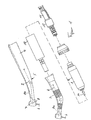
- the dental handpiece assembly consists of a connected to a supply hose package 11 electric drive motor 1, at the free shaft end 1a of the drive shaft portion 2 of a curved grip sleeve 3 having handpiece part 5 is coupled.
- the handpiece part 5 itself has the handle 3, at the outer end of a drill head 7 is arranged, wherein on the opposite end side of the drive motor 1 cross-further sleeve 4 is attached.
- a lighting device 8 is further attached to a supply line 8a.
- the drive motor 1 is designed as a stepping motor having the following properties.
- the stepping motor 1 has a working speed range of 0 to 6000 revolutions per minute and about 100 to 300 revolutions per minute within the so-called start-stop frequency, with its torque range between 0 and about 4 Ncm.
- the stepper motor 1 consisting of a rotor (not shown) with output shaft 1a and a stator (not shown) surrounded by an outer jacket 9 forms a motor cartridge which is inserted into a sleeve-shaped adapter cartridge 10, which in turn in the handpiece part, ie in the at Grip sleeve frontally mounted further sleeve 4 axially inserted and is attached to the grip sleeve 3.
- the connection between the stepper motor 1 and the supply hose package 11 can be done in various ways.
- the output shaft 1a of the stepping motor 1 is directly coupled to the drive shaft section 2 for the tool 6 without a lower or transmission gear.
- D. h. That the drive shaft section 2 rotates at the same speed as the output shaft 1 a of the stepping motor 1.
- the electric drive unit thus by replacing the handle used in each case 3 can be formed either with a reduction gear, with a transmission gear or without a gear only by plugging the respective handle 3 on the adapter cartridge 10.
- Root canals are not rectilinear in practice but are curved or kinked and have different lengths. In this respect, there is an increased risk to the effect that the drill breaks upon reaching such a kink within the root canal or when reaching the root canal end, since the electric drive unit has a high output torque. This happens so quickly and surprisingly that the doctor has no options to prevent the canceling of the drill, for example, by timely switching off or retraction of the electric drive unit.
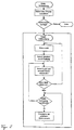
- the electric drive device uses the stepping motor 1 and makes use of the following properties of the stepping motor in a working process according to FIG. 2, for example for a root canal treatment:
- the stepper motor 1 used can be structurally already operate in a speed range between 100 and 300 revolutions per minute within its start-stop frequency. Ie. If the motor is loaded over its set maximum torque, it falls out of step and tries independently to restart and also starts when the torque request goes back again. This "out of step kick” is not only audible but also clearly noticeable by vibrations on the handpiece assembly for the attending physician.
- the "out-of-step fall” of the stepping motor prevents the period between the occurrence of the overload of the stepping motor and the detection or reacting by the Doctor overloading the tool, namely the twist drill beyond the set maximum torque limit, so that in any case a breakage due to a torque overload is prevented.
- the direct drive of the tool by the electric drive unit without reduction or transmission gear allows a substantially accurate adjustment of the maximum achievable torque to the tool by determining the maximum allowable amperage and the speed of the rotating field frequency of the stepping motor.
- speed and torque be set exactly in the stepper motor according to the invention, but also its direction of rotation, so that the following function is made possible.
- the stepper motor within the start-stop frequency is anxious to restart. This leads to a vibration or shaking movement that the doctor feels on the handle.
- the stepping motor or its rotating field frequency as shown in FIG. 2, to control such that the motor alternately changes the direction of rotation so a targeted, defined reciprocating motion (for example, a so-called mit step, in which a forward rotation each greater than the subsequent reverse rotation) possibly with an increased current that is proportional to the torque, which is below the maximum allowable torque and this runs until the drill has torn off again, and then continue to turn in the main direction of rotation.
- This amplifier mode can be initiated either manually by the physician or automatically when the maximum torque is exceeded.
- the stepping motor according to the invention can be accelerated to this speed via a defined acceleration function and likewise falls out of step, ie it stops in this case when the torque applied to the stepping motor exceeds its set maximum torque limit. If the stepping motor according to the invention is operated in this speed range of approximately 2000 revolutions per minute, however, the stepping motor, once it has fallen out of step, can no longer start up by itself. Therefore, in order to accelerate the electric motor back to this speed, the rotating field frequency must be lowered manually, for example via a foot switch below the maximum start-stop speed, so that the engine can be ramped up again to the prescribed by the tool used operating speed.
- the electric drive device can be used for numerous other medical purposes. Since the speed and the torque can be easily and accurately given the stepper motor and thus the speed and the maximum torque can be adjusted to the tool, can be inter alia, cut threads in predrilled holes, as required for example in bone surgery. The thread does not rip, because when the engine is overloaded according to its maximum torque limit, the engine just stops and just tries to restart. Also, in the stepper motor used, the direction of rotation can be reversed in a simple manner, so that drill or tap can be moved out again in a precise manner on reaching a point or penetration depth. Of course, the same applies to the screwing of threaded pins in these threaded holes.
- an electronic control panel may be provided in which a plurality of different types of tools and their technical data are stored. In this way, the attending physician only needs to enter or call the tool type he is using in order to set the implement performance-related to the permissible values of this tool.
- the drive unit according to the invention should be as flexible as possible both in terms of its range of use (different medical uses) and with respect to different handpiece constructions.
- deviations or speed and / or torque fluctuations occur directly on the tool for different handpieces.
- the reason for this is that in particular angle pieces with different Abkrümmwinkeln, materials, drive shaft trains, bearings, etc., in short, handpieces from different manufacturers have different efficiencies. That if a certain torque is set on the stepper motor according to the invention, the maximum torque actually achievable on the drill is reduced according to the efficiency (torque loss, for example due to friction, etc.) according to the handpiece used. The consequence of this is that an exact adjustment of the torque on the tool is virtually impossible.
- a self-calibration process in the form of a specific idling program is initiated by the physician for a transmission or drive shaft train determination, for example after a change of the grip, every time the drive unit is started up and / or in principle at predetermined time intervals.
- This program is started by pressing a calibration start button, not further specified, whereupon the stepping motor is subjected to a minimum electric current in a first method step. This minimum current is selected below the stepper motor own breakaway current or is already default to this value, so that the motor does not start when this current is applied.
- the electric current is increased by a predetermined amount in stages, until the stepping motor starts.
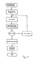
- This start-up of the stepper motor is detected either visually / acoustically by the physician or via a sensor, whereupon the current increase program loop of the calibration process shown in FIG. 3 is ended manually or automatically.
- the process proceeds to the next step, in which the last set electric current is stored as breakaway current in a table. This breakaway current simultaneously represents the leakage current through the angle used and thus indirectly a value for its efficiency.
- a computer executing the program automatically adds the previously measured leakage current to the input value to compensate for the expected loss by the contra-angle or a subsequent transmission. In this way, the maximum torque on the tool corresponds very accurately to the entered current value.
- the calibration described above can also be carried out by the manufacturer of the contra-angle handpieces themselves and specified in the form of an electrically readable code or code that can be manually entered into the computer, for example on the housing of the contra-angle handpiece.
- the invention accordingly relates to an electric drive device for medical applications, in particular for driving drills, cutting and screwing tools.
- Such endo tools have predetermined working speed ranges and, according to their materials and dimensions, have maximum allowable torque load limits.
- the drive unit is equipped with a stepper motor.
- the stepper motor drops out of step upon reaching its maximum torque limit, the maximum torque limit of the stepper motor being set below the torque load limit of the tool.
- the drive unit performs a calibration process in the context of an idle, in which the efficiency of the drive shaft used used to the tool detected and thus the current value for a zero torque is determined.
- condition monitoring method that one type of magazine is prepared for different tools in the form of a number of containers in which the tools are numbered or otherwise coded bunkered.
- a non-illustrated computer which has been pre-entered the number, location, and / or type of each tool, manages these containers and assigns each tool state-specific values, as will be described below.
- the duration of use monitoring program according to FIG. 4 can be either manually before the start of a treatment or automatically at each start-up of an electric drive device in particular a stepping motor can be started, which is used in the case of a root canal treatment.
- the treating physician selects from the magazine a container, preferably filled with only the type of tools which is particularly suitable for the intended treatment, and removes one of these tools from the container. Then the doctor enters the code of this tool in the calculator.
- the computer can be equipped with a suitable sensor that allows him to automatically read in and recognize the selected tool.
- the doctor After the tool, such as a flexible twist drill for root canal preparation, inserted into the handpiece and the computer is informed about the tool used, the doctor begins the treatment in which the drive unit is approached.
- the computer continuously measures, for example, the operating time, the current level as the output value for determining the load level, the speed and / or in the case of a stepping motor, the number of cycles as a reference value driven turns and stores these values as state-specific values in a cache.
- the doctor turns off the drive unit or alternatively enters a termination signal to the computer to indicate the end of treatment for this tool.
- the computer now evaluates the measured and stored state-specific values, which represent a load profile for the past treatment and calculates a theoretical partial load quantity from this. This partial load quantity is now added to a total load amount from possibly previous treatments with the same tool, thus updating the total load quantity for this tool. Then this program is terminated.
- the computer Upon completion of the program flow described above, the computer executes a sterilization cycle monitor program.
- the tool used by the doctor is put back into the container after treatment. Containers and tools are then cleaned and subjected to a sterilization process. It has been shown in experiments that this sterilization process attacks the tools and leads to an accelerated material aging in particular a blunting of the tools. For this reason, the calculator counts the number of sterilization cycles after each treatment, thus updating the total number of sterilization cycles for this tool used.
- the computer now compares, according to FIG. 5, after updating the actual state-specific values, in particular the total number of sterilization cycles and the total load quantity, these actual values with the maximum permissible tool-specific values for the tool used and, when reaching or exceeding one of the Maximum values a warning signal, which indicates to the doctor the necessary replacement of this tool. In this case, the doctor will no longer put the tool in the container, but replace it with a new one.
- the actual state of the tool is determined in this embodiment only after completion of a treatment and compared with the maximum allowable state.
- the maximum period of use i. the predetermined maximum total load amount is reached or even exceeded.
- a safety factor is taken into account in the preferred embodiment in determining the maximum total load amount, which is chosen such that in the context of an average treatment with the appropriate tool, this actual max. Loading quantity can not be achieved.
- the program sequence for the service life monitoring according to FIG. 4 could be changed such that an additional program loop "Detecting the tool state and comparing the actual tool state with the maximum total load quantity" before the in FIG shown step “drill check” is inserted so that a corresponding warning signal may possibly be issued during treatment to the doctor.
- the safety factor for each tool could be reduced and the tool life extended even further.
Landscapes
- Health & Medical Sciences (AREA)
- Life Sciences & Earth Sciences (AREA)
- Engineering & Computer Science (AREA)
- Animal Behavior & Ethology (AREA)
- General Health & Medical Sciences (AREA)
- Public Health (AREA)
- Veterinary Medicine (AREA)
- Oral & Maxillofacial Surgery (AREA)
- Dentistry (AREA)
- Surgery (AREA)
- Epidemiology (AREA)
- Biomedical Technology (AREA)
- Nuclear Medicine, Radiotherapy & Molecular Imaging (AREA)
- Orthopedic Medicine & Surgery (AREA)
- Heart & Thoracic Surgery (AREA)
- Medical Informatics (AREA)
- Molecular Biology (AREA)
- Water Supply & Treatment (AREA)
- Mechanical Engineering (AREA)
- Neurology (AREA)
- Neurosurgery (AREA)
- Biophysics (AREA)
- Dental Tools And Instruments Or Auxiliary Dental Instruments (AREA)
- Details Of Spanners, Wrenches, And Screw Drivers And Accessories (AREA)
Description
Die vorliegende Erfindung bezieht sich auf ein elektrisches Antriebsgerät für Bohrer, Schneidwerkzeuge und Schraubbits, welche zu medizinischen Zwecken herkömmlicherweise verwendet werden sowie ein Verfahren zur Abstimmung des Antriebsgeräts und Überwachung des Zustands des Werkzeugs.The present invention relates to an electric drive apparatus for drills, cutting tools and screw bits conventionally used for medical purposes, and a method of tuning the drive apparatus and monitoring the condition of the tool.
In der Medizin werden derartige Arbeitsgerätschaften beispielsweise in der Zahnmedizin für übliche Wurzelkanalaufbereitungen aber auch für das Aufbohren und Gewindeschneiden in Knochen sowie für das Eindrehen von Stiften verwendet. Auch werden diese Arbeiten manuell vom Zahnarzt bzw. vom Operateur durchgeführt, um Beschädigungen der zu behandelnden Zähne oder Knochen zu vermeiden.In medicine such tools are used for example in dentistry for conventional root canal preparations but also for boring and threading in bones and for screwing pins. Also, this work is done manually by the dentist or the surgeon to avoid damage to the teeth or bones to be treated.
Beispielsweise in der Zahnmedizin werden übliche Wurzelkanalaufbereitungen mittels eines elektrisch angetriebenen Bohrers ausgeführt, der in einem zahnmedizinischen Handstück gelagert ist. Für den Antrieb wird im allgemeinen ein kollektorloser Gleichstromantrieb-verwendet, wie er beispielsweise von der Firma KaVo unter der Bezeichnung "INTRAmatic LUX" vertrieben wird. Diese Art von Antrieb, welche normalerweise für den Betrieb von zahnmedizinischen Bohrwerkzeugen vorgesehen ist, wird mit dem in der Zahnmedizin eingesetzten Steuerungsaufwand in einem untersten Drehzahlbereich von circa 2000 bis 4000 Umdrehungen pro Minute bis in einen obersten Drehzahlbereich von circa 40000 bis 60000 Umdrehungen pro Minute bei einem Drehmoment von 2 bis 3 Ncm betrieben und sind in einem zahnmedizinischen Handstück eingebaut.For example, in dentistry, conventional root canal preparations are carried out by means of an electrically driven drill which is mounted in a dental handpiece. For the drive, a brushless DC drive is generally used, as it is marketed for example by the company KaVo under the name "INTRAmatic LUX". This type of drive, which is normally intended for the operation of dental drilling tools, contributes with the control effort used in dentistry in a lowest speed range of about 2000 to 4000 rpm to a top speed range of about 40,000 to 60,000 rpm a torque of 2 to 3 Ncm and are installed in a dental handpiece.
Zur Wurzelkanalaufbereitung werden indessen flexible Endo-Werkzeuge verwendet, mittels denen Wurzelkanäle, die unterschiedliche Durchmesser und unterschiedlichste Verläufe aufweisen können, ausgeräumt werden. Dies geschieht z. B. mit einem sich zur Spitze hin verjüngenden, flexiblen, spiralförmigen Bohrer von einer Länge von circa 20 bis 30 mm, der sich bei seiner Drehung in den Wurzelkanal schraubt, wobei durch Herausziehen dieses Bohrers der Kanal ausgeräumt wird. Laut Angabe der Hersteller dieser Art von Bohrern beträgt dessen Arbeitsdrehzahlbereich circa 100 bis 500 Umdrehungen pro Minute, in Sonderfällen bis 1800 Umdrehungen pro Minute. Um daher den für derartige Werkzeuge optimalen Arbeitsbereich zu erreichen, müssen bei den gegenwärtig vorgesehenen, für den Einbau in bekannte Griffstücke geeignete Elektromotoren mit dem vorstehend genannten Drehzahl-Spektrum von 2000 bis 40000 Umdrehungen pro Minute Untersetzungen von 1=16-20:1 nachgeschaltet werden. Durch derartige Getriebe wird zwar das Einsatzgebiet bekannter Elektromotoren für den medizinischen Bereich auch auf den Antrieb von flexiblen Spiralbohrern dieser Gattung erweitert. Jedoch bewirkt das Untersetzungsgetriebe gleichzeitig auch eine Drehmomenterhöhung um eben diesen Faktor, reduziert um den Wirkungsgradverlust des Getriebes.For root canal preparation, however, flexible endo tools are used, by means of which root canals, which can have different diameters and very different courses, are cleared away. This happens z. B. with a tapering towards the tip, flexible, helical drill of a length of about 20 to 30 mm, which screws in its rotation in the root canal, which is removed by pulling this drill the channel. According to the manufacturers of this type of drill, its working speed range is approximately 100 to 500 revolutions per minute, in special cases up to 1800 revolutions per minute. Therefore, in order to achieve the optimum working range for such tools, in the currently provided, suitable for installation in known grips electric motors with the above-mentioned speed spectrum from 2000 to 40000 revolutions per minute reductions of 1 = 16-20: 1 must be followed , By such a gear while the field of application of known electric motors for the medical field is also extended to the drive of flexible twist drills of this genus. However, the reduction gear simultaneously causes an increase in torque by just this factor, reduced by the loss of efficiency of the transmission.
Untersuchungen der Erfinderin haben ergeben, daß mit diesem Drehmoment nahezu alle zur Zeit eingesetzten Endo-Werkzeuge beispielsweise zur Wurzelkanalaufbereitung mehrfach über deren Bruchgrenze belastet werden. Es hat sich nämlich gezeigt, daß beispielsweise flexible Spiralbohrer für das Ausräumen von Wurzelkanälen bis nur maximal 0,2 Ncm belastet werden dürfen. Bei einem Überschreiten dieser Drehmomentgrenze kann der Spiralbohrer abbrechen und in dem zu behandelnden Wurzelkanal stecken bleiben. Derartige Unfälle lassen sich oft nur durch einen operativen Eingriff beheben.Investigations by the inventor have shown that with this torque almost all Endo tools currently used, for example for root canal preparation, are loaded several times beyond their breaking point. It has been shown that, for example, flexible twist drills for the removal of root canals to a maximum of 0.2 Ncm may be charged. If this torque limit is exceeded, the twist drill can break off and get stuck in the root canal to be treated. Such accidents can often only be remedied by surgery.
Als ein relevanter Stand der Technik sei auf die DE 196 28 854 A verwiesen. Hieraus ist ein elektrisches Antriebsgerät für medizinische Bohr-, Schneid- und Schraubwerkzeuge bekannt mit jeweils einem vorbestimmten Umdrehungsbereich und einer maximal zulässigen Drehmomentbelastungsgrenze, wobei ein elektrischer Motor für den rotatorischen Antrieb des Werkzeugs vorgesehen ist.As a relevant prior art, reference is made to DE 196 28 854 A. From this, an electric drive device for medical drilling, cutting and screwing tools is known, each having a predetermined revolution range and a maximum allowable torque load limit, wherein an electric motor is provided for the rotational drive of the tool.
Aus der EP-A-0 812 578 ist ebenfalls ein gattungsgemäßen elektrisches Antriebsgerät bekannt, das einen Schrittmotor als Antrieb für das Werkzeug verwendet. Ein solcher Schrittmotor hat dabei die Eigenschaft, dass er bei Erreichen einer maximalen Drehmomentgrenze außer Tritt fällt, d.h. dem vorgegebenen fixen Drehfeld nacheilt und schließlich stehen bleibt. Aus diesem Grund wird der aus diesem Stand der Technik bekannte Schrittmotor so ausgelegt, dass es im normalen Betrieb diese maximale Drehmomentgrenze nicht erreicht.From EP-A-0 812 578 a generic electric drive device is also known, which uses a stepping motor as a drive for the tool. Such a stepper motor has the characteristic that it falls out of step on reaching a maximum torque limit, i. lags behind the given fixed rotating field and finally stops. For this reason, the known from this prior art stepper motor is designed so that it does not reach this maximum torque limit in normal operation.
Angesichts dieses Stands der Technik liegt der Erfindung die Aufgabe zugrunde, ein elektrisches Antriebsgerät für medizinische Endo-Werkzeuge zu schaffen, dessen Drehzahl- und Drehmomentbereich unter geringem regelungstechnischen Aufwand derart variabel einstellbar ist, daß das elektrische Antriebsgerät bei nahezu sämtlichen Endo-Werkzeugen insbesondere für das Bohren und auch Gewinde Schneiden und Stift Eindrehen verwendet werden kann.In view of this state of the art, the invention has for its object to provide an electric drive device for medical Endo tools, its speed and torque range is so variably adjustable under low control effort that the electric drive unit can be used in almost all Endo tools especially for drilling and thread cutting and pin screwing.
Diese Aufgabe wird erfindungsgemäß durch ein elektrisches Antriebsgerät für medizinische Werkzeuge mit den Merkmalen des Patentanspruchs 1 sowie durch ein erfindungsgemäßes Verfahren gemäß Anspruch 9 zur Anpassungen bzw. Eichung des Antriebsgeräts gelöst, wodurch ein exaktes Einstellen des maximalen Drehmoments ermöglicht wird.This object is achieved by an electric drive device for medical tools with the features of claim 1 and by an inventive method according to
Die Erfindung besteht demzufolge in der Ausbildung eines elektrischen Antriebsgeräts für medizinische Bohr-, Schneid- und Schraubwerkzeuge mit jeweils einem vorbestimmten Umdrehungsbereich und einer maximal zulässigen Drehmomentbelastungsgrenze, das einen elektrischen Schrittmotor umfaßt, dessen maximales Drehmoment und Drehzahl über die Stromstärke und die Drehfeldfrequenz vorgegeben werden kann. Umfangreiche Experimente erbrachten das Ergebnis, daß mit einem Schrittmotor als Antrieb für derzeit bekannte Endo-Werkzeuge deren Abbrechen im praktischen Einsatz verhindert wird. Hierbei macht man sich den Effekt des "außer Tritt Fallens" von Schrittmotoren zunutze, der maximal ein Blockieren des Motors bei Überlastung bewirkt. Der regelungstechnische Aufwand bleibt dabei äußerst gering und beschränkt sich im wesentlichen auf das Einstellen der Stromstärke und der Impulsgebung für den Schrittmotor.The invention therefore consists in the formation of an electric drive device for medical drilling, cutting and screwing tools, each having a predetermined revolution range and a maximum allowable torque load limit, which includes an electric stepper motor whose maximum torque and speed can be set via the current and the rotating field frequency , Extensive experiments yielded the result that with a stepper motor as a drive for currently known Endo tools their break in practical use is prevented. In doing so, one makes use of the effect of "stepping out of stepping" of stepper motors, which maximally causes the motor to block when overloaded. The control engineering effort remains extremely low and is essentially limited to the setting of the current and the pulse for the stepper motor.
Es ist ein besonderes Ziel der Erfindung, daß das vorstehend beschriebene Antriebsgerät für unterschiedliche Handstücke und somit unterschiedliche Triebwellenzüge verwendbar sein muß, die wiederum verschiedene Wirkungsgrade aufweisen. In anderen Worten ausgedrückt, stimmt die am Motor eingestellte maximale Drehmomentgrenze bei Handstücken nicht mit dem unmittelbar am Werkzeug maximal aufbringbaren Drehmoment überein. Das erfindungsgemäße Verfahren zur Abstimmung des Antriebsgeräts sieht demzufolge einen Selbsteichungsschritt (Kalibrierschritt) vor, der beispielsweise bei in Betriebnahme, nach einem Wechsel des Hand- oder Griffstücks bzw. des Triebwellenzugs, und/oder aber auch in bestimmten Zeitintervallen durchgeführt wird. Prinzipiell wird hierbei der erfindungsgemäße Schrittmotor mit einem vorbestimmten minimalen elektrischen Strom unterhalb des Losbrechstroms beaufschlagt. Daraufhin wird der Strom stufenweise erhöht, solange, bis der Schrittmotor anläuft. Der letzte Stromwert, der ein Anlaufen der Schrittmotors bewirkt, wird als jener Strom gespeichert, der zur Überwindung der Reibung des Triebwellenzugs notwendig ist und der folglich dem Strom des Antriebsgeräts proportional ist.It is a particular object of the invention that the drive unit described above for different handpieces and thus different drive shaft trains must be usable, which in turn have different efficiencies. In other words, the maximum torque limit set on the motor for handpieces does not match the maximum torque that can be directly applied to the tool. The inventive method for tuning the drive unit Consequently, a self-calibration step (calibration step) is provided, which is carried out, for example, during startup, after a change of the hand or grip piece or the drive shaft train, and / or else at specific time intervals. In principle, in this case the stepper motor according to the invention is subjected to a predetermined minimum electric current below the break-away current. Then the current is increased gradually until the stepper motor starts. The last current value which causes starting of the stepping motor is stored as the current which is necessary to overcome the friction of the drive shaft train and which consequently is proportional to the current of the drive device.
Das elektrisches Antriebsgerät gemäß der Erfindung ist dadurch weitergebildet, daß eine Abtriebswelle des Schrittmotors mit oder ohne Unter- oder Übersetzung an das Werkzeug gekoppelt ist, wobei der Schrittmotor vorteilhafterweise ohne Unter-/Übersetzung einen Arbeitsdrehzahlbereich von 100 bis 300 Umdrehungen pro Minute hat und bei einer Belastung gleich oder größer als sein eingestelltes Drehmoment außer Tritt fällt.The electric drive device according to the invention is further developed in that an output shaft of the stepper motor is coupled with or without translation or translation to the tool, the stepper motor advantageously without under / translation a working speed range of 100 to 300 revolutions per minute and at Load equal to or greater than its adjusted torque out of step.
Ferner ist es vorgesehen, daß der Arbeitsdrehzahlbereich das Start-Stop-Geschwindigkeitsspektrum des Schrittmotors ist, innerhalb dem der Schrittmotor nach außer Tritt Fallen bei Verringerung der Drehmomentbelastung selbständig wieder anläuft, wobei es nach Anspruch 4 auch vorteilhaft ist, wenn der Schrittmotor auch außerhalb seines Start-Stop-Geschwindigkeitsspektrums bis zu einer Geschwindigkeit von 6000 Umdrehungen pro Minute betrieben werden kann.Furthermore, it is provided that the working speed range is the start-stop speed spectrum of the stepping motor, within which the stepping motor automatically restarts after falling out of traction while reducing the torque load, and it is also advantageous according to
Die vorstehend beschriebene Entwicklung ermöglicht somit den erweiterten Einsatz elektrischer Antriebe auf Werkzeuge mit geringer Bruchlast bei einer erheblichen Verringerung der Gefahr eines Abbrechens des Werkzeugs. Damit wird die Möglichkeit eröffnet, ein Werkzeug mehrmals zu verwenden. Es hat sich nunmehr herausgestellt, daß die von der Erfinderin zwischenzeitlich ermittelten Bruchbelastungsgrenzen für Endo-Werkzeuge mit zunehmender Einsatzdauer Veränderungen unterworfen sind. Im Rahmen von Versuchen konnte somit analytisch für einige Endo-Werkzeuge eine Maximal-Verwendungsdauer ermittelt werden, innerhalb der die Bruchwahrscheinlichkeit gering und die Schneidfähigkeit der Werkzeuge ausreichend ist. Bei Überschreiten dieser Maximal-Verwendungsdauer zeigten sich vermehrt Brüche in Folge von Materialermüdung sowie eine erhebliche Verschlechterung des erzielten Schnittbildes.The development described above thus allows the extended use of electric drives on tools with low breaking load with a significant reduction in the risk of a breakage of the tool. This opens up the possibility of using a tool several times. It has now been found that by the inventor In the meantime, fracture load limits for endo tools have been subject to changes with increasing service life. Within the scope of experiments, it was thus possible to analytically determine a maximum period of use for some Endo tools within which the probability of breakage is low and the cutting ability of the tools is sufficient. Exceeding this maximum period of use showed increased fractures as a result of material fatigue and a significant deterioration of the obtained cross-sectional image.
Um somit die Leistungsfähigkeit sowie das Sicherheitspotential des von der Erfinderin neu entwickelten Antriebskonzeptes voll ausnützen zu können, ist eine möglichst genaue Kenntnis über den Zustand des verwendeten Werkzeugs erforderlich, um in jedem Fall ein Abbrechen, nicht etwa in Folge eines unsachgemäßen Antriebs (Überlastung), sondern in Folge einer Materialermüdung bei zu langem Einsatz zu verhindern.In order to be able to fully exploit the performance and the safety potential of the drive concept newly developed by the inventor, the most accurate possible knowledge of the state of the tool used is required in each case a cancel, not as a result of improper drive (overload), but to prevent as a result of material fatigue when used too long.
Angesichts dieser Problematik ist es nunmehr auch technisch sinnvoll, ein neues Verfahren zur Zustandserkennung eines medizinischen Werkzeugs, insbesondere eines Endo-Werkzeugs bereitzustellen.In view of this problem, it is now also technically sensible to provide a new method for detecting the state of a medical tool, in particular an endo tool.
Es wird ein Verfahren zur Überwachung des Zustands eines medizinischen Werkzeugs, insbesondere eines Endo-Werkzeugs vorgeschlagen, welches zumindest die nachfolgenden Schritte umfaßt:
- a. Eingeben einer werkzeugspezifischen, d.h. bezüglich eines bestimmten Werkzeugs vorab ermittelten, maximal zulässigen Belastungsmenge in einen Rechner,
- b) Erfassen einer Teilbelastungsmenge resultierend aus einer aktuellen Behandlung und Addieren dieser Teilbelastungsmenge zu einer zustandsspezifischen Gesamtbelastungsmenge resultierend aus vorhergehenden Behandlungen,
- c. Vergleichen der maximal zulässigen Belastungsmenge mit der aktualisierten Gesamtbelastungsmenge und
- d) Ausgeben eines Austauschsignals, falls die Gesamtbelastungsmenge die zulässige Belastungsmenge erreicht oder überschreitet.
- a. Entering a tool-specific, ie with respect to a specific tool previously determined, maximum allowable load quantity in a computer,
- b) detecting a partial load amount resulting from a current treatment and adding this partial load amount to a state-specific total load amount resulting from previous treatments;
- c. Comparing the maximum allowable load amount with the updated total load amount and
- d) outputting an exchange signal if the total load amount reaches or exceeds the allowable load amount.
Durch das vorstehend beschriebene Verfahren wird folglich für ein Werkzeug, z.B. einen flexiblen Spiralbohrer eine Maximalbelastungsmenge ermittelt für die das Risiko eines Bruchs minimal ist und fortlaufend die Ist-Belastungsmenge für dieses Werkzeug erfaßt und mit der Maximalbelastungsmenge verglichen. Auf diese Weise kann ein ausreichend guter Zustand des Werkzeugs gewährleistet werden.By the method described above, therefore, for a tool, e.g. a flexible twist drill determines a maximum load quantity for which the risk of breakage is minimal and continuously detects the actual load quantity for this tool and compared with the maximum load quantity. In this way, a sufficiently good state of the tool can be ensured.
Hierbei ist die Belastungsmenge als eine theoretische Größe definiert, welche aus der gefahrenen Umdrehungszahl bzw. Umdrehungsgeschwindigkeit, dem Drehmoment, sowie der Behandlungsdauer bestimmt wird. Zusätzlich oder alternativ kann die Anzahl an Sterilisationszyklen als Größe für die Belastungsmenge dienen.Here, the load quantity is defined as a theoretical quantity, which is determined from the number of revolutions or revolution speed, the torque, and the duration of the treatment. Additionally or alternatively, the number of sterilization cycles may serve as a magnitude for the amount of stress.
Weitere vorteilhafte Ausführungen der Erfindung sind dabei Gegenstand der Unteransprüche.Further advantageous embodiments of the invention are the subject of the dependent claims.
Die Erfindung wird nachstehend anhand eines bevorzugten Ausführungsbeispiels unter Bezugnahme auf die begleitende Zeichnung näher erläutert.
- Fig. 1 zeigt als ein mögliches Anwendungsbeispiel der Erfindung den generellen Aufbau eines in der Zahnmedizin allgemein verwendeten Winkelstücks zur Lagerung von Bohrern sowie zur Aufnahme eines elektrischen Antriebsmotors,
- Fig. 2 zeigt ein Flußdiagramm bezüglich eines erfindungsgemäßen Arbeitsverfahrens bei einer Wurzelkanalbehandlung
- Fig. 3 zeigt ein Flußdiagramm bezüglich eines Selbsteichungsprozesses.
- Fig. 4 zeigt ein Flußdiagramm bezüglich eines Programmablaufs für eine Einsatzdauer-Überwachung und
- Fig. 5 zeigt ein Flußdiagramm bezüglich des Programmablaufs für eine Sterilisationszyklus-Überwachung am Beispiel eines Spiralbohrers.
- 1 shows, as a possible application example of the invention, the general construction of an angle piece generally used in dentistry for mounting drills and for receiving an electric drive motor,
- FIG. 2 shows a flowchart relating to a method according to the invention for root canal treatment
- Fig. 3 shows a flowchart relating to a self-calibration process.
- Fig. 4 shows a flowchart relating to a program flow for a usage duration monitoring and
- FIG. 5 shows a flowchart relating to the program sequence for a sterilization cycle monitoring using the example of a twist drill.
Wie aus der Fig. 1 zu entnehmen ist, besteht die zahnmedizinische Handstückanordnung aus einem an einem Versorgungsschlauchpaket 11 angeschlossenen elektrischen Antriebsmotor 1, an dessen freiem Wellenende 1a der Triebwellenabschnitt 2 eines eine gekrümmte Griffhülse 3 aufweisenden Handstückteils 5 angekoppelt ist. Das Handstückteil 5 selbst hat das Griffstück 3, an dessen äußerem Ende ein Bohrkopf 7 angeordnet ist, wobei an der gegenüberliegenden Stirnseite eine den Antriebsmotor 1 übergreifende weitere Hülse 4 befestigt ist. An dem Bohrkopf 7, welcher ein Werkzeug, vorliegend einen Dentalbohrer 6 drehbar aufnimmt, ist ferner eine Beleuchtungseinrichtung 8 mit einer Versorgungsleitung 8a angebracht.As can be seen from Fig. 1, the dental handpiece assembly consists of a connected to a supply hose package 11 electric drive motor 1, at the free shaft end 1a of the drive shaft portion 2 of a
Erfindungsgemäß ist der Antriebsmotor 1 als ein Schrittmotor ausgebildet, der die nachfolgenden Eigenschaften aufweist.According to the invention, the drive motor 1 is designed as a stepping motor having the following properties.
Der Schrittmotor 1 hat einen Arbeitsdrehzahlbereich von 0 bis 6000 Umdrehungen pro Minute und ca. 100 bis 300 Umdrehungen pro Minute innerhalb der sogenannten Start-Stop-Frequenz, wobei dessen Drehmomentbereich zwischen 0 und ca. 4 Ncm liegt. Der Schrittmotor 1 bestehend aus einem Rotor (nicht gezeigt) mit Abtriebswelle 1a und einem Stator (nicht gezeigt) umgeben von einem Außenmantel 9 bildet eine Motorpatrone, die in eine hülsenförmige Adapterpatrone 10 eingesteckt ist, das wiederum in dem Handstückteil, d. h. in der an der Griffhülse stirnseitig befestigten weiteren Hülse 4 axial eingeschoben und an der Griffhülse 3 befestigt ist. Der Anschluß zwischen dem Schrittmotor 1 und dem Versorgungsschlauchpaket 11 kann auf verschiedene Arten erfolgen.The stepping motor 1 has a working speed range of 0 to 6000 revolutions per minute and about 100 to 300 revolutions per minute within the so-called start-stop frequency, with its torque range between 0 and about 4 Ncm. The stepper motor 1 consisting of a rotor (not shown) with output shaft 1a and a stator (not shown) surrounded by an
Wie ferner in der Fig. 1 dargestellt wird, ist die Abtriebswelle 1a des Schrittmotors 1 unmittelbar an den Triebwellenabschnitt 2 für das Werkzeug 6 ohne ein Unter- oder Übersetzungsgetriebe angekoppelt. D. h., daß der Triebwellenabschnitt 2 mit der gleichen Umdrehungszahl dreht, wie die Abtriebswelle 1a des Schrittmotors 1. Natürlich kann in dem gekrümmten Griffstück 3 auch ein Untersetzungs- oder Übersetzungsgetriebe untergebracht sein, wobei das elektrische Antriebsgerät somit durch Austausch des jeweils verwendeten Griffstücks 3 wahlweise mit einem Untersetzungsgetriebe, mit einem Übersetzungsgetriebe oder ohne ein Getriebe lediglich durch Aufstecken des jeweiligen Griffstücks 3 auf die Adapterpatrone 10 ausgebildet werden kann.As further shown in Fig. 1, the output shaft 1a of the stepping motor 1 is directly coupled to the drive shaft section 2 for the tool 6 without a lower or transmission gear. D. h., That the drive shaft section 2 rotates at the same speed as the output shaft 1 a of the stepping motor 1. Of course, in the
Der Entwicklung des erfindungsgemäßen elektrischen Antriebsgeräts bestehend aus dem Schrittmotor 1 mit einer Umdrehungszahl von 0 bis 6000 Umdrehungen pro Minute und einem Drehmomentbereich zwischen 0 und 4 Ncm, der Abtriebswelle 1a des Schrittmotors 1 sowie dem Triebwellenabschnitt 2 sind zahlreiche Versuche insbesondere hinsichtlich der Belastungsfähigkeit der mit diesem elektrischen Antriebsgerät zu betreibenden Endo-Werkzeuge vorhergegangen, auf die nachfolgend kurz eingegangen werden soll:The development of the electric drive device according to the invention consisting of the stepping motor 1 with a number of revolutions of 0 to 6000 revolutions per minute and a torque range between 0 and 4 Ncm, the output shaft 1a of the stepping motor 1 and the drive shaft section 2 are numerous attempts, in particular with regard to the load capacity of this electric drive device to be operated Endo tools, which will be briefly discussed below:
Zuerst wurden Versuche mit flexiblen Endo-Werkzeugen für zahnmedizinische Zwecke insbesondere zur Wurzelkanalaufbereitung durchgeführt. Wie eingangs bereits kurz ausgeführt wurde, sind diese Endo-Werkzeuge in Form von flexiblen, spiralförmigen Bohrern ausgebildet, die sich zur Spitze hin verjüngen und vorzugsweise aus Nickel-TitanLegierung oder Stahl gefertigt sind. Die maximal zulässige Drehzahl derartiger Bohrer beträgt circa 100 bis 1800 Umdrehungen pro Minute. Die Versuche haben gezeigt, daß feine Bohrer dieser Gattung schon bei einem Drehmoment von circa 0,2 Ncm brechen, wobei bei Überschreiten dieser Drehmomentgrenze vorwiegend am äußersten Endbereich des Bohrers ein Bruch auftritt. Weitere praxisnahe Versuche mit derzeit bekannten elektrischen Antriebsgeräten zum Antreiben der vorstehend spezifizierten spiralförmigen Bohrer haben gezeigt, daß die herausgefundene maximale Drehmomentgrenze von 0,2 Ncm überschritten wird. Wurzelkanäle verlaufen in der Praxis nicht geradlinig sondern sind gekrümmt oder abgeknickt und weisen unterschiedliche Längen auf. Insofern tritt eine erhöhte Gefahr dahingehend auf, daß der Bohrer bei Erreichen einer derartigen Knickstelle innerhalb des Wurzelkanals oder bei Erreichen des Wurzelkanalendes bricht, da das elektrische Antriebsgerät ein zu hohes Abtriebsmoment aufweist. Dies geschieht so schnell und überraschend, daß der behandelnde Arzt keine Möglichkeiten hat, dem Abbrechen des Bohrers beispielsweise durch rechtzeitiges Ausschalten oder Rückziehen des elektrischen Antriebsgerätes vorzubeugen.First, experiments were carried out with flexible Endo tools for dental purposes, in particular for root canal preparation. As already briefly explained, these endo tools are designed in the form of flexible, spiral-shaped drills which taper towards the tip and are preferably made of nickel-titanium alloy or steel. The maximum permissible speed of such drills is approximately 100 to 1800 revolutions per minute. The experiments have shown that fine Drills of this genus already break at a torque of about 0.2 Ncm, with a break occurs when exceeding this torque limit mainly at the extreme end of the drill. Further practical experiments with currently known electric drive devices for driving the above-specified helical drills have shown that the found maximum torque limit of 0.2 Ncm is exceeded. Root canals are not rectilinear in practice but are curved or kinked and have different lengths. In this respect, there is an increased risk to the effect that the drill breaks upon reaching such a kink within the root canal or when reaching the root canal end, since the electric drive unit has a high output torque. This happens so quickly and surprisingly that the doctor has no options to prevent the canceling of the drill, for example, by timely switching off or retraction of the electric drive unit.
Das erfindungsgemäße elektrische Antriebsgerät verwendet indessen gemäß vorstehender Beschreibung den Schrittmotor 1 und macht sich dabei bei einem Arbeitsvorgang gemäß Fig. 2 beispielsweise für eine Wurzelkanalbehandlung die folgenden Eigenschaften des Schrittmotors zunutze:Meanwhile, according to the above description, the electric drive device according to the invention uses the stepping motor 1 and makes use of the following properties of the stepping motor in a working process according to FIG. 2, for example for a root canal treatment:
Der verwendete Schrittmotor 1 läßt sich konstruktiv bedingt bereits in einem Drehzahlbereich zwischen 100 und 300 Umdrehungen pro Minute innerhalb seiner Start-Stop-Frequenz betreiben. D. h. wird der Motor über dessen eingestelltes maximales Drehmoment belastet, fällt er außer Tritt und versucht selbständig wieder anzulaufen und läuft auch an, wenn die Drehmomentanforderung wieder zurückgeht. Dieses "außer Tritt Fallen" ist nicht nur hörbar sondern auch durch Vibrationen an der Handstückanordnung für den behandelnden Arzt eindeutig spürbar. Das "außer Tritt Fallen" des Schrittmotors verhindert im Zeitraum zwischen dem Auftreten der Überbelastung des Schrittmotors und dem Erkennen bzw. Reagieren durch den Arzt eine Überlastung des Werkzeugs, nämlich des Spiralbohrers über die eingestellte maximale Drehmomentgrenze hinaus, so daß in jedem Fall ein Bruch infolge einer Drehmomentüberlastung verhindert wird.The stepper motor 1 used can be structurally already operate in a speed range between 100 and 300 revolutions per minute within its start-stop frequency. Ie. If the motor is loaded over its set maximum torque, it falls out of step and tries independently to restart and also starts when the torque request goes back again. This "out of step kick" is not only audible but also clearly noticeable by vibrations on the handpiece assembly for the attending physician. The "out-of-step fall" of the stepping motor prevents the period between the occurrence of the overload of the stepping motor and the detection or reacting by the Doctor overloading the tool, namely the twist drill beyond the set maximum torque limit, so that in any case a breakage due to a torque overload is prevented.
Des weiteren ermöglicht der Direktantrieb des Werkzeuges durch das elektrische Antriebsgerät ohne Untersetzungs- oder Übersetzungsgetriebe eine im wesentlichen genaue Einstellung des maximal erreichbaren Drehmoments an dem Werkzeug durch Bestimmung der maximal zulässigen Stromstärke sowie der Drehzahl über die Drehfeldfrequenz des Schrittmotors. Es lassen sich bei dem erfindungsgemäßen Schrittmotor jedoch nicht nur Drehzahl und Drehmoment exakt einstellen sonder auch dessen Drehrichtung, wodurch die folgende Funktion ermöglicht wird.Furthermore, the direct drive of the tool by the electric drive unit without reduction or transmission gear allows a substantially accurate adjustment of the maximum achievable torque to the tool by determining the maximum allowable amperage and the speed of the rotating field frequency of the stepping motor. However, not only can speed and torque be set exactly in the stepper motor according to the invention, but also its direction of rotation, so that the following function is made possible.
Unter der Annahme, daß sich beispielsweise der Bohrer zum Ausräumen eines Wurzelkanals festgefressen und das Antriebsgerät in Folge der überhöhten Drehmomentbelastung außer Tritt gefallen ist, so ist der Schrittmotor innerhalb der Start-Stop-Frequenz bestrebt, wieder anzulaufen. Dies führt zu einer Vibration oder Rüttelbewegung, die der Arzt am Griffstück fühlt. Es besteht nunmehr die Möglichkeit den Schrittmotor bzw. dessen Drehfeldfrequenz wie in der Fig. 2 dargestellt ist, derart zu steuern, daß der Motor abwechselnd die Drehrichtung ändert also eine gezielte, definierte Hin- und Herbewegung (beispielsweise ein sogenannter Pilgerschritt, bei dem eine Vorwärtsdrehung jeweils größer ist als die darauffolgende Rückwärtsdrehung) ggf. mit einer erhöhten Stromstärke, die proportional dem Drehmoment ist, das unterhalb des maximal zulässigen Drehmoments liegt und diese solange ausführt, bis sich der Bohrer wieder losgerissen hat, um dann in die Hauptdrehrichtung weiterzudrehen. Dieser Verstärkermodus kann entweder manuell durch den Arzt oder automatisch bei Überschreiten des maximalen Drehmoments eingeleitet werden.Assuming, for example, that the drill has seized to clear a root canal and the drive unit has fallen out of step due to the excessive torque load, the stepper motor within the start-stop frequency is anxious to restart. This leads to a vibration or shaking movement that the doctor feels on the handle. There is now the possibility of the stepping motor or its rotating field frequency as shown in FIG. 2, to control such that the motor alternately changes the direction of rotation so a targeted, defined reciprocating motion (for example, a so-called pilgrim step, in which a forward rotation each greater than the subsequent reverse rotation) possibly with an increased current that is proportional to the torque, which is below the maximum allowable torque and this runs until the drill has torn off again, and then continue to turn in the main direction of rotation. This amplifier mode can be initiated either manually by the physician or automatically when the maximum torque is exceeded.
Des weiteren hat sich gezeigt, daß sich auch solche Werkzeuge mittels des erfindungsgemäßen elektrischen Antriebsgerätes betreiben lassen, die bei einer höheren Drehzahl z. B. bei 2000 Umdrehungen pro Minute arbeiten, also außerhalb der Start-Stop-Drehzahl. Der erfindungsgemäße Schrittmotor kann in diesem Fall über eine definierte Beschleunigungsfunktion auf diese Geschwindigkeit beschleunigt werden und fällt dabei ebenfalls außer Tritt, d. h. er bleibt in diesem Falle stehen, wenn das den Schrittmotor beaufschlagende Drehmoment dessen eingestellte maximale Drehmomentgrenze überschreitet. Wird der erfindungsgemäße Schrittmotor in diesem Drehzahlbereich von circa 2000 Umdrehungen pro Minute betrieben, kann jedoch der Schrittmotor, wenn er einmal außer Tritt gefallen ist, nicht mehr selbständig anlaufen. Um den Elektromotor daher wieder auf diese Drehzahl zu beschleunigen, muß die Drehfeldfrequenz manuell beispielsweise über einen Fußschalter unter die maximale Start-Stop-Geschwindigkeit abgesenkt werden, damit der Motor von neuem auf die durch das verwendete Werkzeug vorgeschriebene Arbeitsgeschwindigkeit hochgefahren werden kann.Furthermore, it has been found that even such tools by means of the electric drive device according to the invention operate, which at a higher speed z. B. operate at 2000 revolutions per minute, ie outside the start-stop speed. In this case, the stepping motor according to the invention can be accelerated to this speed via a defined acceleration function and likewise falls out of step, ie it stops in this case when the torque applied to the stepping motor exceeds its set maximum torque limit. If the stepping motor according to the invention is operated in this speed range of approximately 2000 revolutions per minute, however, the stepping motor, once it has fallen out of step, can no longer start up by itself. Therefore, in order to accelerate the electric motor back to this speed, the rotating field frequency must be lowered manually, for example via a foot switch below the maximum start-stop speed, so that the engine can be ramped up again to the prescribed by the tool used operating speed.
Aus der vorstehenden Beschreibung des erfindungsgemäßen elektrischen Antriebsgerätes läßt sich erkennen, daß dieses zu zahlreichen anderen medizinischen Zwecken angewendet werden kann. Da die Drehzahl sowie das Drehmoment leicht und exakt dem Schrittmotor vorgegeben werden können und damit auch die Drehzahl sowie das maximale Drehmoment an dem Werkzeug eingestellt werden kann, lassen sich unter anderem auch Gewinde in vorgebohrten Bohrungen schneiden, wie sie beispielsweise in der Knochenchirurgie benötigt werden. Das Gewinde reißt nicht aus, da bei Überlastung des Motors entsprechend dessen maximaler Drehmomentgrenze der Motor einfach stehen bleibt und nur versucht, wieder anzulaufen. Auch läßt sich bei dem verwendeten Schrittmotor die Drehrichtung in einfacher Weise umkehren, so daß Bohrer oder Gewindebohrer bei Erreichen eines Punktes bzw. Eindringtiefe in exakter Weise wieder herausgefahren werden kann. Das gleiche gilt natürlich auch für das Eindrehen von Gewindestiften in diese Gewindebohrungen.From the above description of the electric drive device according to the invention can be seen that this can be used for numerous other medical purposes. Since the speed and the torque can be easily and accurately given the stepper motor and thus the speed and the maximum torque can be adjusted to the tool, can be inter alia, cut threads in predrilled holes, as required for example in bone surgery. The thread does not rip, because when the engine is overloaded according to its maximum torque limit, the engine just stops and just tries to restart. Also, in the stepper motor used, the direction of rotation can be reversed in a simple manner, so that drill or tap can be moved out again in a precise manner on reaching a point or penetration depth. Of course, the same applies to the screwing of threaded pins in these threaded holes.
Als eine zusätzliche Einrichtung für das erfindungsgemäße Arbeitsgerät kann ein elektronischer Schaltpult vorgesehen sein, in dem eine Vielzahl von unterschiedlichen Werkzeugtypen sowie deren technische Daten abgespeichert sind. Auf diese Weise braucht der behandelnde Arzt lediglich den von ihm benutzten Werkzeugtyp einzugeben oder aufzurufen, um das Arbeitsgerät leistungstechnisch auf die zulässigen Werte dieses Werkzeugs einzustellen.As an additional device for the working device according to the invention, an electronic control panel may be provided in which a plurality of different types of tools and their technical data are stored. In this way, the attending physician only needs to enter or call the tool type he is using in order to set the implement performance-related to the permissible values of this tool.
Als weitere mögliche Anwendungsbereiche seien die Folgenden genannt:
- 1. Im Falle einer Kariesbehandlung läßt sich der Umstand zunutze machen, daß ein Karies befallener Zahnschmelz eine geringere Härte besitzt, als ein gesunder Zahnschmelz. D.h. erkrankte Zahnbereiche verändern ihre Struktur und damit ihre Festigkeit und Härte gegenüber gesunden Zahnbereichen. Der Schrittmotor kann nunmehr so eingestellt werden, daß das maximal abgebbare Drehmoment zwar ausreicht, einen Bohrer in das erkrankte Zahnmaterial zu treiben, um dieses auszuräumen. Sobald jedoch der Bohrer auf den gesunden Zahnschmelz trifft, überschreitet das aufgebrachte Drehmoment diese maximale Drehmomentgrenze, worauf der Schrittmotor stoppt. Gesunder Zahnschmelz bleibt dadurch nahezu vollständig erhalten. Im übrigen verursacht ein derart betriebener Bohrer geringere Vibrationen, die im Falle des Entfernes von gesundem Zahnschmelz verstärkt auftreten würden, wodurch Schmerzen, verursacht durch eine Traumatisierung, d.h. ein Zusammensrücken der Nervenkammer während der Zahnbehandlung, reduziert werden.
- 2. Gleiches gilt auch beispielsweise bei der Entfernung von Zahnstein, welches gegenüber dem Zahnschmelz ebenfalls andere Eigenschaften bezüglich Härte und Festigkeit besitzt, auf die das erfindungsgemäße Antriebsgerät hinsichtlich einer optimalen Drehzahl und Drehmomentgrenze eingestellt werden kann.
- 1. In the case of a caries treatment can take advantage of the fact that a caries infested enamel has a lower hardness, as a healthy tooth enamel. That is, diseased tooth areas change their structure and thus their strength and hardness compared to healthy tooth areas. The stepper motor can now be adjusted so that the maximum deliverable torque is indeed sufficient to drive a drill in the diseased tooth material in order to clear this. However, as soon as the drill encounters the healthy enamel, the applied torque exceeds this maximum torque limit, whereupon the stepper motor stops. Healthy enamel remains almost completely preserved. Incidentally, a drill thus operated causes less vibration that would be exacerbated in the case of removal of healthy enamel, thereby reducing pain caused by trauma, ie, collapse of the nerve chamber during dental treatment.
- 2. The same applies, for example, in the removal of tartar, which also has other properties with respect to hardness and strength compared to the enamel to which the drive unit according to the invention can be adjusted with respect to an optimal speed and torque limit.
Wie eingangs kurz erwähnt wurde, soll das erfindungsgemäße Antriebsgerät sowohl hinsichtlich seines Verwendungsbereichs (unterschiedliche medizinische Einsatzmöglichkeiten) als auch hinsichtlich unterschiedlicher Handstückkonstruktionen möglichst flexibel sein. Im Rahmen der zahlreichen Versuche wurde herausgefunden, daß trotz exakt einstellbarer Drehzahlen und Drehmomente am Schrittmotor selbst, Abweichungen bzw. Drehzahl- und/oder Drehmomentschwanken direkt am Werkzeug für unterschiedliche Handstücke auftreten. Der Grund hierfür besteht darin, daß insbesondere Winkelstücke mit unterschiedlichen Abkrümmwinkeln, Materialien, Antriebswellenzügen, Lagerungen usw., kurz gesagt, Handstücke unterschiedlicher Hersteller voneinander abweichende Wirkungsgrade besitzen. D.h. wird ein bestimmtes Drehmoment am erfindungsgemäßen Schrittmotor eingestellt, so wird das tatsächlich am Bohrer erreichbare maximale Drehmoment entsprechend dem Wirkungsgrad (Drehmomentverlust z.B. durch Reibung usw.) entsprechend des verwendeten Handstücks verringert. Die Folge hiervon ist, daß eine exakte Einstellung des Drehmoments am Werkzeug praktisch unmöglich wird.As briefly mentioned above, the drive unit according to the invention should be as flexible as possible both in terms of its range of use (different medical uses) and with respect to different handpiece constructions. In the context of numerous experiments has been found that despite accurately adjustable speeds and torques on the stepper motor itself, deviations or speed and / or torque fluctuations occur directly on the tool for different handpieces. The reason for this is that in particular angle pieces with different Abkrümmwinkeln, materials, drive shaft trains, bearings, etc., in short, handpieces from different manufacturers have different efficiencies. That if a certain torque is set on the stepper motor according to the invention, the maximum torque actually achievable on the drill is reduced according to the efficiency (torque loss, for example due to friction, etc.) according to the handpiece used. The consequence of this is that an exact adjustment of the torque on the tool is virtually impossible.
Die Lösung dieses Problem besteht in dem erfindungsgemäßen Selbsteinchungsprozeß, wie er in der Fig. 3 dargestellt ist.The solution to this problem consists in the Selbsteinchungsprozeß invention, as shown in FIG. 3.
Gemäß dieser Fig. 3 wird für eine Getriebe- bzw. Triebwellenzug-Bestimmung z.B. nach einem Wechsel des Griffstücks, bei jeder Inbetriebnahme des Antriebsgeräts und/oder aber auch grundsätzlich in vorbestimmten Zeitintervallen durch den Arzt ein Selbsteichungsprozeß in Form eines bestimmten Leerlaufprogramms eingeleitet. Dieses Programm wird gestartet durch Betätigen einer nicht weiter aufgeführten Eichungs-Starttaste, worauf der Schrittmotor in einem ersten Verfahrensschritt mit einem minimalen elektrischen Strom beaufschlagt wird. Dieser Minimalstrom wird unterhalb des Schrittmotor eigenen Losbrechstroms gewählt oder ist bereits standartgemäß auf diesen Wert voreingestellt, so daß der Motor bei Anlegen dieses Stroms nicht anläuft.According to this FIG. 3, a self-calibration process in the form of a specific idling program is initiated by the physician for a transmission or drive shaft train determination, for example after a change of the grip, every time the drive unit is started up and / or in principle at predetermined time intervals. This program is started by pressing a calibration start button, not further specified, whereupon the stepping motor is subjected to a minimum electric current in a first method step. This minimum current is selected below the stepper motor own breakaway current or is already default to this value, so that the motor does not start when this current is applied.
Nach jeweils einer bestimmten Anzahl von Drehfeldfortschaltungen wird der elektrische Strom um ein vorbestimmtes Maß stufenweise erhöht, solange, bis der Schrittmotor anläuft. Dieses Anfahren des Schrittmotors wird entweder visuell/akustisch durch den Arzt oder über einen Sensor erfaßt, worauf die in Fig. 3 dargestellte Stromerhöhungs-Programmschleife des Eichungsprozesses manuell oder automatisch beendet wird. Mit Beendigung dieser Programmschleife, schreitet der Vorgang zum nächsten Schritt fort, in welchem der zuletzt eingestellte elektrische Strom als Losbrechstrom in einer Tabelle abgespeichert wird. Dieser Losbrechstrom stellt gleichzeitig auch den Verluststrom durch das verwendete Winkelstück und damit indirekt einen Wert für dessen Wirkungsgrad dar.After a certain number of rotary field progressions, the electric current is increased by a predetermined amount in stages, until the stepping motor starts. This start-up of the stepper motor is detected either visually / acoustically by the physician or via a sensor, whereupon the current increase program loop of the calibration process shown in FIG. 3 is ended manually or automatically. Upon completion of this program loop, the process proceeds to the next step, in which the last set electric current is stored as breakaway current in a table. This breakaway current simultaneously represents the leakage current through the angle used and thus indirectly a value for its efficiency.
Wird nunmehr die gewünschte Stromstärke entsprechend dem zu verwendenden Werkzeug oder der beabsichtigten Behandlungsart vom Arzt eingegeben, addiert ein das Programm ausführender Rechner automatisch den zuvor gemessenen Verluststrom zu dem eingegebenen Wert hinzu, um den zu erwartenden Verlust durch das Winkelstück oder ein nachfolgendes Getriebe auszugleichen. Auf diese Weise entspricht das maximale Drehmoment am Werkzeug sehr exakt dem eingegebenen Stromwert.Now, if the desired current intensity is entered by the physician according to the tool or the intended treatment, a computer executing the program automatically adds the previously measured leakage current to the input value to compensate for the expected loss by the contra-angle or a subsequent transmission. In this way, the maximum torque on the tool corresponds very accurately to the entered current value.
Die vorstehend beschriebene Eichung kann alternativ auch bereits durch die Hersteller der Winkelstücke selbst standartgemäß durchgeführt und in Form eines elektrisch lesbaren oder auch manuell in den Rechner eingebbaren Codes beispielsweise auf dem Gehäuse des Winkelstücks angegeben werden. D.h. Winkelstücke, Handstücke, Triebwellenzüge usw. werden ab Werk mit einer Wirkungsgradangabe versehen, die dann entweder der Arzt bei der Eingabe des Maximalstromwerts berücksichtigt oder aber vom Rechner über einen geeigneten Sensor erkennt und als Verluststrom bei der Korrektur der manuell eingegebenen Stromtabelle verwendet.Alternatively, the calibration described above can also be carried out by the manufacturer of the contra-angle handpieces themselves and specified in the form of an electrically readable code or code that can be manually entered into the computer, for example on the housing of the contra-angle handpiece. This means that contra-angles, handpieces, drive-shaft pulls, etc. are provided ex works with an efficiency value which is then taken into account either by the physician when entering the maximum current value or by the computer via a suitable one Sensor detects and uses as leakage current when correcting the manually entered current table.
Die Erfindung bezieht sich demzufolge auf ein elektrisches Antriebsgerät für medizinische Anwendungen insbesondere zum Antrieb von Bohrern, Schneid- und Schraubwerkzeugen. Derartige Endo-Werkzeuge haben vorbestimmte Arbeitsdrehzahlbereiche und besitzen entsprechend deren Materialien und Dimensionen maximal zulässige Drehmomentbelastungsgrenzen. Um ein Überschreiten dieser individuellen Drehmomentbelastungsgrenzen zu vermeiden, ist das Antriebsgerät mit einem Schrittmotor ausgerüstet. Der Schrittmotor fällt bei Erreichen dessen maximaler Drehmomentgrenze außer Tritt, wobei die maximale Drehmomentgrenze des Schrittmotors unterhalb der Drehmomentsbelastungsgrenze des Werkzeuges festgelegt wird. Um die Drehmomentbelasungsgrenze exakt einstellen zu können, führt das Antriebsgerät einen Eichungsvorgang im Rahmen eines Leerlaufs durch, bei dem der Wirkungsgrad des verwendeten Triebwellenzugs bis zum Werkzeug erfaßt und damit der Stromwert für ein Null-Drehmoment ermittelt wird.The invention accordingly relates to an electric drive device for medical applications, in particular for driving drills, cutting and screwing tools. Such endo tools have predetermined working speed ranges and, according to their materials and dimensions, have maximum allowable torque load limits. To avoid exceeding these individual torque load limits, the drive unit is equipped with a stepper motor. The stepper motor drops out of step upon reaching its maximum torque limit, the maximum torque limit of the stepper motor being set below the torque load limit of the tool. In order to adjust the Drehmomentbelasungsgrenze exactly, the drive unit performs a calibration process in the context of an idle, in which the efficiency of the drive shaft used used to the tool detected and thus the current value for a zero torque is determined.
Für die nachfolgende Beschreibung des Zustandsüberwachungsverfahrens gemäß einem bevorzugten Ausführungsbeispiel der Erfindung sei darauf hingewiesen, daß eine Art Magazin für unterschiedliche Werkzeuge in Form einer Anzahl von Behältern oder Kästchen vorbereitet ist, in denen die Werkzeuge nummeriert oder anderweitig codiert gebunkert sind. Ein nicht weiter dargestellter Rechner, welchem die Anzahl, Lage, und/oder Art der einzelnen Werkzeuge vorab eingegeben worden ist, verwaltet diese Behälter und ordnet jedem Werkzeug zustandsspezifische Werte zu, wie nachfolgend noch beschrieben wird.It should be noted for the following description of the condition monitoring method according to a preferred embodiment of the invention that one type of magazine is prepared for different tools in the form of a number of containers in which the tools are numbered or otherwise coded bunkered. A non-illustrated computer, which has been pre-entered the number, location, and / or type of each tool, manages these containers and assigns each tool state-specific values, as will be described below.
Das Einsatzdauer-Überwachungsprogramm gemäß der Fig. 4 kann entweder manuell vor Beginn einer Behandlung oder automatisch bei jeder Inbetriebnahme eines elektrischen Antriebsgeräts insbesondere eines Schrittmotors gestartet werden, der im Fall einer Wurzelbehandlung eingesetzt wird.The duration of use monitoring program according to FIG. 4 can be either manually before the start of a treatment or automatically at each start-up of an electric drive device in particular a stepping motor can be started, which is used in the case of a root canal treatment.
Zu Beginn wählt der behandelnde Arzt aus dem Magazin einen Behälter, vorzugsweise gefüllt mit nur der Art von Werkzeugen, welche für die beabsichtigte Behandlung besonders geeignet ist, aus und entnimmt eines dieser Werkzeuge aus dem Behälter. Anschließend gibt der Arzt den Code dieses Werkzeugs in den Rechner ein. Alternativ hierzu kann der Rechner mit einer geeigneten Sensorik ausgestattet sein, die ihm ein automatisches Einlesen und Erkennen des ausgewählten Werkzeugs ermöglicht.Initially, the treating physician selects from the magazine a container, preferably filled with only the type of tools which is particularly suitable for the intended treatment, and removes one of these tools from the container. Then the doctor enters the code of this tool in the calculator. Alternatively, the computer can be equipped with a suitable sensor that allows him to automatically read in and recognize the selected tool.
Wie eingangs bereits angedeutet wurde, lassen sich für jedes beispielsweise in der Zahnmedizin verwendete Werkzeug spezielle Werte hinsichtlich max. Umdrehungszahl und Belastung, Einsatzdauer usw. sowie eine Maximalzahl an Sterilisationszyklen analytisch ermitteln, aus denen eine maximale Belastungsmenge als eine theoretische Größe bestimmt werden kann, bei deren Überschreiten ein erheblicher Anstieg an Ermüdungsbrüchen festzustellen ist. Diese maximal zulässigen Werte bzw. die max. Belastungsmenge werden dem Rechner für jedes im Magazin befindliche Werkzeug bei dessen Einsortieren entweder manuell oder automatisch per Sensor eingegeben, so daß der Rechner bei entsprechendem Code-Aufruf die werkzeugspezifischen Werte aufrufen kann.As already indicated at the beginning, special values with regard to max. Determine rotational speed and load, duration of use, etc., as well as a maximum number of sterilization cycles, from which a maximum load can be determined as a theoretical size, exceeding a significant increase in fatigue fractures is observed. These maximum permissible values or the max. Load amounts are the calculator for each tool in the magazine when it is sorted either manually or automatically entered by sensor, so that the computer can call the tool-specific values with appropriate code call.
Nachdem das Werkzeug, beispielsweise ein flexibler Spiralbohrer für eine Wurzelkanalaufbereitung, in das Handstück eingesetzt und der Rechner über das verwendete Werkzeug informiert ist, beginnt der Arzt mit der Behandlung, in dem das Antriebsgerät angefahren wird. Mit Anfahren des Antriebsgeräts mißt der Rechner fortlaufend beispielsweise die Betriebszeitdauer, die Stromhöhe als Ausgangswert zur Bestimmung der Belastungshöhe, die Drehzahl und/oder im Falle eines Schrittmotors die Anzahl von Takten als Referenzwert gefahrener Umdrehungen und speichert diese Werte als zustandsspezifische Werte in einem Zwischenspeicher ab.After the tool, such as a flexible twist drill for root canal preparation, inserted into the handpiece and the computer is informed about the tool used, the doctor begins the treatment in which the drive unit is approached. When starting the drive unit, the computer continuously measures, for example, the operating time, the current level as the output value for determining the load level, the speed and / or in the case of a stepping motor, the number of cycles as a reference value driven turns and stores these values as state-specific values in a cache.
Nach Beendigung der Behandlung schaltet der Arzt das Antriebsgerät ab oder gibt alternativ ein Beendigungssignal dem Rechner ein, um diesem das Behandlungsende für dieses Werkzeug anzuzeigen. Der Rechner wertet nunmehr die gemessenen und abgespeicherten zustandsspezifischen Werte aus, welche ein Belastungsprofil für die vergangene Behandlung darstellen und errechnet hieraus eine theoretische Teilbelastungsmenge. Diese Teilbelastungsmenge wird nunmehr einer Gesamtbelastungsmenge aus ggf. vorhergehenden Behandlungen mit dem selben Werkzeug hinzu addiert, um somit die Gesamtbelastungsmenge für dieses Werkzeug zu aktualisieren. Hierauf wird dieses Programm beendet.After completion of the treatment, the doctor turns off the drive unit or alternatively enters a termination signal to the computer to indicate the end of treatment for this tool. The computer now evaluates the measured and stored state-specific values, which represent a load profile for the past treatment and calculates a theoretical partial load quantity from this. This partial load quantity is now added to a total load amount from possibly previous treatments with the same tool, thus updating the total load quantity for this tool. Then this program is terminated.
Nach Beendigung des vorstehend beschriebenen Programmablauf führt der Rechner ein Sterilisationszyklen-Überwachungsprogramm aus.Upon completion of the program flow described above, the computer executes a sterilization cycle monitor program.
Das vom Arzt verwendete Werkzeug wird nach der Behandlung in den Behälter zurückgesteckt. Behälter und Werkzeuge werden anschließend gereinigt und einem Sterilisationsvorgang unterzogen. Es hat sich in Versuchen gezeigt, daß dieser Sterilisationsvorgang die Werkzeuge angreift und zu einer beschleunigten Materialalterung insbesondere einem Abstumpfen der Werkzeuge führt. Aus diesem Grunde zählt der Rechner nach jeder Behandlung die Anzahl an Sterilisationszyklen, um somit die Gesamtzahl an Sterilisationszyklen für dieses verwendete Werkzeug zu aktualisieren.The tool used by the doctor is put back into the container after treatment. Containers and tools are then cleaned and subjected to a sterilization process. It has been shown in experiments that this sterilization process attacks the tools and leads to an accelerated material aging in particular a blunting of the tools. For this reason, the calculator counts the number of sterilization cycles after each treatment, thus updating the total number of sterilization cycles for this tool used.
Der Rechner vergleicht nunmehr gemäß der Fig. 5 nach Aktualisieren der tatsächlichen zustandsspezifischen Werte, insbesondere der Gesamtzahl an Sterilisationszyklen sowie der Gesamtbelastungsmenge diese Ist-Werte mit den maximal zulässigen, werkzeugspezifischen Werten für das verwendete Werkzeug und gibt bei Erreichen oder Überschreiten eines der Maximalwerte ein Warnsignal aus, welches dem Arzt den notwendigen Austausch dieses Werkzeugs anzeigt. In diesem Fall wird der Arzt das Werkzeug nicht mehr im Behälter ablegen, sondern durch ein Neues ersetzen.The computer now compares, according to FIG. 5, after updating the actual state-specific values, in particular the total number of sterilization cycles and the total load quantity, these actual values with the maximum permissible tool-specific values for the tool used and, when reaching or exceeding one of the Maximum values a warning signal, which indicates to the doctor the necessary replacement of this tool. In this case, the doctor will no longer put the tool in the container, but replace it with a new one.
Wie aus der vorstehenden Beschreibung ersichtlich ist, wird in diesem Ausführungsbeispiel erst nach Beendigung einer Behandlung der Ist-Zustand des Werkzeugs ermittelt und mit dem maximal zulässigen Zustand verglichen. Es kann jedoch der Fall auftreten, daß bereits während einer Behandlung beispielsweise die maximale Benutzungsdauer d.h. die vorbestimmte maximale Gesamtbelastungsmenge erreicht oder sogar überschritten wird. Um dieses Problem auf einfache Weise zu lösen, wird gemäß dem bevorzugten Ausführungsbeispiel bei der Bestimmung der maximalen Gesamtbelastungsmenge ein Sicherheitsfaktor mit eingerechnet, der derart gewählt ist, daß im Rahmen einer durchschnittlichen Behandlung mit dem entsprechenden Werkzeug diese tatsächliche max. Belastungsmenge nicht erreicht werden kann.As can be seen from the above description, the actual state of the tool is determined in this embodiment only after completion of a treatment and compared with the maximum allowable state. However, it may be the case that even during a treatment, for example, the maximum period of use, i. the predetermined maximum total load amount is reached or even exceeded. To solve this problem in a simple manner, a safety factor is taken into account in the preferred embodiment in determining the maximum total load amount, which is chosen such that in the context of an average treatment with the appropriate tool, this actual max. Loading quantity can not be achieved.
Alternativ zu dieser einfachen Vorgehensweise, könnte insbesondere der Programmablauf für die Einsatzdauer-Überwachung gemäß der Fig. 4 derart geändert werden, daß eine zusätzliche Programmschlaufe "Erfassen des Werkzeugzustands und Vergleich des Ist-Werkzeugzustand mit der max. Gesamtbelastungsmenge" vor dem in Fig. 4 gezeigten Schritt "Bohrer prüfen" eingefügt wird, so daß ein entsprechendes Warnsignal ggf. auch während der Behandlung an den Arzt ausgegeben werden kann. In diesem Fall könnte der Sicherheitsfaktor für jedes Werkzeug reduziert und die Standzeit des Werkzeugs noch weiter verlängert werden.As an alternative to this simple procedure, in particular the program sequence for the service life monitoring according to FIG. 4 could be changed such that an additional program loop "Detecting the tool state and comparing the actual tool state with the maximum total load quantity" before the in FIG shown step "drill check" is inserted so that a corresponding warning signal may possibly be issued during treatment to the doctor. In this case, the safety factor for each tool could be reduced and the tool life extended even further.
Claims (12)
- Electrical drive device for medical boring, cutting and screwing instruments (6) having respectively a predetermined speed range and a maximum permissible torque loading limit, characterised by an electrical step motor (1), the maximum torque and the speed of which are prescribable via the current strength and the rotational field frequency, such that the step motor slips out of synchronism upon reaching its maximum torque limit which is set via the current strength, within its operating speed range which is set via the rotational field frequency, the maximum torque limit being specified below the torque loading limit of the tool, and the operating speed range being the start-stop speed spectrum of the step motor (1), within which the step motor (1) automatically starts again after slipping out of synchronism upon reduction of the torque loading.
- Electrical drive device according to claim 1, characterised in that a driven shaft (1a) of the step motor (1) is connected to the instrument (6) with/without stepping down or up.
- Electrical drive device according to one of the preceding claims, characterised in that the step motor (1), without stepping down/up, has an operating speed range of 100 to 300 revolutions per minute and slips out of synchronism at a loading equal to or greater than its set torque.
- Electrical drive device according to one of the preceding claims, characterised in that the step motor (1) can be operated outwith its start-stop speed spectrum up to a speed of 6000 revolutions per minute.
- Electrical drive device according to one of the preceding claims, characterised in that the output torque of the step motor (1) is between 0 and 4 Ncm.
- Electrical drive device according to one of the preceding claims, characterised in that the step motor (1) can be controlled, at least upon reaching or exceeding the maximum torque, in a booster mode, in which the step motor implements a defined left-right movement, for example a pilger step, in order then, upon falling below the maximum torque, to rotate further in its preferred direction.
- Electrical drive device according to claim 6, characterised in that the left-right movement is restricted respectively to a predetermined number of degrees.
- Electrical drive device according to one of the preceding claims, characterised in that the drive device is a dental handpiece with an elbow, in which a drive shaft cable, which can be driven by the step motor (1), is mounted.
- Method for self-calibration of an electrical drive device with the features according to one of the preceding claims, characterised by the following method steps:a) supplying the motor (1) with a minimum current below the motor-specific breakaway current,b) increasing the current stepwise according to specific rotational field rapid reclosing,c) detecting the current value at which the motor (1) starts.
- Method according to claim 9, characterised in that the detected current value is stored as leakage current and is added on to the input maximum current.
- Method according to one of the claims 9 and 10, characterised in that the self-calibration is implemented when starting the motor (1) and/or when changing the drive device and/or after a predetermined or determinable period of time.
- Method according to one of the preceding claims, characterised in that the leakage current is input in the form of a code which is preferably already provided on the drive device and can be detected electronically or is input manually by the dentist, the leakage current being determined already in the factory.
Applications Claiming Priority (5)
| Application Number | Priority Date | Filing Date | Title |
|---|---|---|---|
| DE19820640A DE19820640A1 (en) | 1998-05-08 | 1998-05-08 | Monitoring condition of electrical dental implement, flexible tool for root canal work |
| DE19820639 | 1998-05-08 | ||
| DE19820640 | 1998-05-08 | ||
| DE19820639A DE19820639A1 (en) | 1997-09-26 | 1998-05-08 | Electrical drive apparatus for medical boring, cutting and screwing tools |
| PCT/EP1999/003174 WO1999058076A1 (en) | 1998-05-08 | 1999-05-10 | Working device for drilling, cutting and screwdriver instruments used for medical purposes |
Publications (2)
| Publication Number | Publication Date |
|---|---|
| EP1049416A1 EP1049416A1 (en) | 2000-11-08 |
| EP1049416B1 true EP1049416B1 (en) | 2007-01-03 |
Family
ID=26046061
Family Applications (1)
| Application Number | Title | Priority Date | Filing Date |
|---|---|---|---|
| EP99924915A Expired - Lifetime EP1049416B1 (en) | 1998-05-08 | 1999-05-10 | Working device for drilling, cutting and screwdriver instruments used for medical purposes |
Country Status (6)
| Country | Link |
|---|---|
| US (1) | US6616446B1 (en) |
| EP (1) | EP1049416B1 (en) |
| JP (1) | JP2002514464A (en) |
| BR (1) | BR9906430A (en) |
| DE (1) | DE59914125D1 (en) |
| WO (1) | WO1999058076A1 (en) |
Families Citing this family (67)
| Publication number | Priority date | Publication date | Assignee | Title |
|---|---|---|---|---|
| US7695485B2 (en) | 2001-11-30 | 2010-04-13 | Power Medical Interventions, Llc | Surgical device |
| US7032798B2 (en) * | 1999-06-02 | 2006-04-25 | Power Medical Interventions, Inc. | Electro-mechanical surgical device |
| US6793652B1 (en) | 1999-06-02 | 2004-09-21 | Power Medical Interventions, Inc. | Electro-mechanical surgical device |
| US8016855B2 (en) | 2002-01-08 | 2011-09-13 | Tyco Healthcare Group Lp | Surgical device |
| DE10030114A1 (en) | 2000-06-19 | 2001-12-20 | Kaltenbach & Voigt | Dental hand piece for a dental instrument to remove material working of a tooth root canal has a setting device to selectively activate and deactivate an arrangement for reducing the torque |
| AT412321B (en) * | 2000-07-13 | 2005-01-25 | W & H Dentalwerk Buermoos Gmbh | CONTROL DEVICE AND METHOD FOR OPERATING A DENTAL OR SURGICAL HANDPIECE |
| EP2316345B1 (en) * | 2001-06-22 | 2016-12-21 | Covidien LP | Electro-mechanical surgical device |
| US9113878B2 (en) | 2002-01-08 | 2015-08-25 | Covidien Lp | Pinion clip for right angle linear cutter |
| DE10219166B4 (en) * | 2002-04-29 | 2005-11-24 | Heribert Schmid | Medical treatment device |
| PT1515651E (en) | 2002-06-14 | 2007-03-30 | Power Med Interventions Inc | Device for clamping, cutting, and stapling tissue |
| WO2004019803A1 (en) * | 2002-08-28 | 2004-03-11 | Heribert Schmid | Dental treatment system |
| US6955536B1 (en) * | 2002-09-24 | 2005-10-18 | Buchanan L Stephen | Motor control system for endodontic handpiece providing dynamic torque limit tracking of specific file fatigue |
| US6829565B2 (en) * | 2003-02-14 | 2004-12-07 | Xerox Corporation | Stepper motor automated self-test routine |
| US20060234185A1 (en) * | 2005-02-17 | 2006-10-19 | Discus Dental Impressions Inc. | Ultrasonic dental tool having a light source |
| GB0503529D0 (en) * | 2005-02-21 | 2005-03-30 | Smith & Nephew Inc | Medical device |
| US20060206100A1 (en) * | 2005-03-09 | 2006-09-14 | Brasseler Usa Medical Llc | Surgical apparatus and power module for same, and a method of preparing a surgical apparatus |
| FR2884635B1 (en) * | 2005-04-13 | 2007-07-27 | Xelyx Sarl | CUTTING TOOL MANAGEMENT SYSTEM |
| US20080268397A1 (en) * | 2005-10-20 | 2008-10-30 | Graham John W | Method and System for Temporary Skeletal Anchorage in Orthodontics |
| GB0601361D0 (en) * | 2006-01-24 | 2006-03-01 | Shuster David M | Dental apparatus |
| DE102006016448A1 (en) * | 2006-04-07 | 2007-10-11 | Robert Bosch Gmbh | Electric machine tool and method of operating the same |
| CN100455269C (en) * | 2006-06-27 | 2009-01-28 | 胡文广 | Multi-core flexible-shaft drill for plastic surgery |
| WO2008021507A2 (en) * | 2006-08-17 | 2008-02-21 | Discus Dental, Llc | Ultrasonic dental tool |
| EP3097869B1 (en) | 2007-09-21 | 2020-03-11 | Covidien LP | Surgical device |
| CA2921566C (en) | 2007-09-21 | 2018-05-22 | Tyco Healthcare Group Lp | Surgical device |
| EP2073359A1 (en) * | 2007-12-20 | 2009-06-24 | SycoTec GmbH & Co. KG | Tube motor |
| EP2073349B1 (en) * | 2007-12-20 | 2011-06-15 | SycoTec GmbH & Co. KG | Electrical motor with media conduits through the stator |
| US8435034B2 (en) * | 2008-03-18 | 2013-05-07 | Zila, Inc. | Rotatable ultrasonic dental tool |
| JP5315766B2 (en) * | 2008-04-17 | 2013-10-16 | ペンタックスリコーイメージング株式会社 | Aperture drive device for interchangeable lens camera |
| WO2010029741A1 (en) | 2008-09-11 | 2010-03-18 | Ntn株式会社 | Remote control actuator |
| JP5213735B2 (en) * | 2009-01-23 | 2013-06-19 | Ntn株式会社 | Remote control type actuator |
| EP2371304A4 (en) | 2008-11-27 | 2013-10-09 | Ntn Toyo Bearing Co Ltd | Remote control actuator |
| JP5213666B2 (en) * | 2008-11-27 | 2013-06-19 | Ntn株式会社 | Remote control type actuator |
| WO2010066337A1 (en) * | 2008-12-09 | 2010-06-17 | Vdw Gmbh | Endodontic device and method for operating a device of said kind |
| JP5588020B2 (en) | 2010-02-16 | 2014-09-10 | カーディアック ペースメイカーズ, インコーポレイテッド | Dynamics of physiological responses to movements in daily life movements |
| JP4916037B2 (en) * | 2010-07-02 | 2012-04-11 | 株式会社ナカニシ | Motor control method and control device for dental handpiece |
| US8292150B2 (en) | 2010-11-02 | 2012-10-23 | Tyco Healthcare Group Lp | Adapter for powered surgical devices |
| CN103379875B (en) * | 2011-05-27 | 2015-05-13 | 株式会社中西 | Dental handpiece control device |
| US9908182B2 (en) | 2012-01-30 | 2018-03-06 | Black & Decker Inc. | Remote programming of a power tool |
| US9974627B2 (en) * | 2012-04-06 | 2018-05-22 | Aseptico Inc. | Method for cutting or abrading with a tool, and related drivers and systems |
| EP2662972B1 (en) * | 2012-05-07 | 2019-12-11 | Kaltenbach & Voigt GmbH | Method for operating an electric motor of a medical instrument and dental system |
| US8919456B2 (en) | 2012-06-08 | 2014-12-30 | Black & Decker Inc. | Fastener setting algorithm for drill driver |
| CN105491965B (en) * | 2013-07-19 | 2018-01-12 | 普罗德克斯有限公司 | Limit the screwdriver of moment of torsion |
| US10011006B2 (en) | 2013-08-08 | 2018-07-03 | Black & Decker Inc. | Fastener setting algorithm for drill driver |
| EP4344684A2 (en) | 2013-12-17 | 2024-04-03 | Standard Bariatrics Inc. | Resection line guide for a medical procedure |
| US20150272582A1 (en) * | 2014-03-26 | 2015-10-01 | Ethicon Endo-Surgery, Inc. | Power management control systems for surgical instruments |
| WO2015153340A2 (en) | 2014-03-29 | 2015-10-08 | Standard Bariatrics, Inc. | End effectors surgical stapling devices, and methods of using same |
| EP3125796B1 (en) | 2014-03-29 | 2024-03-06 | Standard Bariatrics Inc. | Surgical stapling devices |
| US10357871B2 (en) | 2015-04-28 | 2019-07-23 | Milwaukee Electric Tool Corporation | Precision torque screwdriver |
| CN208729640U (en) | 2015-04-28 | 2019-04-12 | 米沃奇电动工具公司 | A kind of rotary power tool and the transducer assemblies for it |
| US10285837B1 (en) | 2015-09-16 | 2019-05-14 | Standard Bariatrics, Inc. | Systems and methods for measuring volume of potential sleeve in a sleeve gastrectomy |
| CN109475375B (en) | 2016-06-07 | 2022-02-15 | 普罗德克斯有限公司 | Torque limiting screwdriver device, system and method |
| US20180206938A1 (en) * | 2016-09-07 | 2018-07-26 | Dentsply Sirona Inc. | Dental device with load-responsive motor control |
| US10357333B2 (en) * | 2016-11-14 | 2019-07-23 | Imam Abdulrahman Bin Faisal University | Endodontic file system for cleaning and shaping a root canal |
| US10912562B2 (en) | 2017-08-14 | 2021-02-09 | Standard Bariatrics, Inc. | End effectors, surgical stapling devices, and methods of using same |
| US11278297B2 (en) | 2017-08-17 | 2022-03-22 | Stryker Corporation | Handheld surgical instrument and method for supplying tactile feedback to a user during a kickback event |
| EP3678560A4 (en) * | 2017-09-09 | 2021-05-19 | June Medical IP, LLC | Passive safety intraosseous device |
| US10814468B2 (en) | 2017-10-20 | 2020-10-27 | Milwaukee Electric Tool Corporation | Percussion tool |
| CN214723936U (en) | 2018-01-26 | 2021-11-16 | 米沃奇电动工具公司 | Impact tool |
| KR102045331B1 (en) * | 2018-02-27 | 2019-11-15 | 신대건 | Method of calculating and applying implant placement value |
| EP3840918B1 (en) | 2018-08-20 | 2024-03-13 | Pro-Dex, Inc. | Torque-limiting devices |
| CN108857577B (en) * | 2018-08-31 | 2021-08-10 | 上海实极机器人自动化有限公司 | Cutter wear state monitoring method and equipment |
| JP7224950B2 (en) * | 2019-02-18 | 2023-02-20 | 株式会社マキタ | electric work machine |
| JP7281917B2 (en) * | 2019-02-18 | 2023-05-26 | 株式会社マキタ | electric work machine |
| US11633259B2 (en) * | 2019-08-15 | 2023-04-25 | MDT Micro Diamond Technologies Ltd. | Handpiece adapter for an endodontic file |
| EP4054492A4 (en) | 2019-11-04 | 2023-11-01 | Standard Bariatrics, Inc. | Systems and methods of performing surgery using laplace's law tension retraction during surgery |
| DE102020109932A1 (en) * | 2020-04-09 | 2021-10-14 | Aesculap Ag | Adaptive tool operation |
| EP4294283A1 (en) | 2021-03-23 | 2023-12-27 | Standard Bariatrics, Inc. | Systems and methods for preventing tissue migration in surgical staplers |
Citations (1)
| Publication number | Priority date | Publication date | Assignee | Title |
|---|---|---|---|---|
| EP0189537A1 (en) * | 1984-12-19 | 1986-08-06 | Preh Industrieausrüstungen GmbH | Motor device |
Family Cites Families (6)
| Publication number | Priority date | Publication date | Assignee | Title |
|---|---|---|---|---|
| US5538423A (en) * | 1993-11-26 | 1996-07-23 | Micro Motors, Inc. | Apparatus for controlling operational parameters of a surgical drill |
| US5543695A (en) * | 1993-12-15 | 1996-08-06 | Stryker Corporation | Medical instrument with programmable torque control |
| JP3264607B2 (en) * | 1995-07-28 | 2002-03-11 | 株式会社モリタ製作所 | Motor control device for dental handpiece |
| FR2749751B1 (en) * | 1996-06-12 | 1998-11-27 | Micro Mega Int Mfg Sa | CONTRA-ANGLE HANDPIECE ASSEMBLY WITH A STEPPING MOTOR |
| US6017354A (en) * | 1996-08-15 | 2000-01-25 | Stryker Corporation | Integrated system for powered surgical tools |
| DE29712012U1 (en) * | 1997-07-08 | 1997-11-13 | Kaltenbach & Voigt | Storage for a medical treatment instrument, medical treatment tool or a drive motor |
-
1999
- 1999-05-10 WO PCT/EP1999/003174 patent/WO1999058076A1/en active IP Right Grant
- 1999-05-10 JP JP2000547929A patent/JP2002514464A/en active Pending
- 1999-05-10 DE DE59914125T patent/DE59914125D1/en not_active Expired - Lifetime
- 1999-05-10 BR BR9906430-8A patent/BR9906430A/en not_active Application Discontinuation
- 1999-05-10 EP EP99924915A patent/EP1049416B1/en not_active Expired - Lifetime
-
2000
- 2000-01-07 US US09/479,138 patent/US6616446B1/en not_active Expired - Fee Related
Patent Citations (1)
| Publication number | Priority date | Publication date | Assignee | Title |
|---|---|---|---|---|
| EP0189537A1 (en) * | 1984-12-19 | 1986-08-06 | Preh Industrieausrüstungen GmbH | Motor device |
Also Published As
| Publication number | Publication date |
|---|---|
| DE59914125D1 (en) | 2007-02-15 |
| US6616446B1 (en) | 2003-09-09 |
| JP2002514464A (en) | 2002-05-21 |
| EP1049416A1 (en) | 2000-11-08 |
| BR9906430A (en) | 2000-07-11 |
| WO1999058076A1 (en) | 1999-11-18 |
Similar Documents
| Publication | Publication Date | Title |
|---|---|---|
| EP1049416B1 (en) | Working device for drilling, cutting and screwdriver instruments used for medical purposes | |
| DE60032144T2 (en) | ROTATING HANDPIECE FOR AN ENDODONTIC INSTRUMENT | |
| DE602005002271T2 (en) | DENTAL ULTRASONIC TOOL | |
| EP2138255B1 (en) | Trepan | |
| WO2010066337A1 (en) | Endodontic device and method for operating a device of said kind | |
| DE202012002636U1 (en) | Screw implant for a jawbone with coronal compression thread and apical self-tapping thread | |
| DE19628854A1 (en) | Motor control unit for a dental handpiece | |
| DE102011016518A1 (en) | Medical or dental hand part | |
| DE69731996T2 (en) | Motor or handpiece assembly with a stepper motor | |
| DE102011105958B4 (en) | Rotating handpiece for root canal preparation | |
| EP1084683A2 (en) | Method and device for limiting the moment of momentum in dental and chirurgical handpieces | |
| DE19820639A1 (en) | Electrical drive apparatus for medical boring, cutting and screwing tools | |
| DE69818638T4 (en) | DENTAL IMPLANT | |
| DE102019121121A1 (en) | Medical drive unit of the handheld design with sensor device and kick-back control | |
| EP2193757B1 (en) | Torque transmission device for a surgical or dental rotating instrument | |
| EP0681462B1 (en) | Dental treatment instruments | |
| DE19820640A1 (en) | Monitoring condition of electrical dental implement, flexible tool for root canal work | |
| DE10219166B4 (en) | Medical treatment device | |
| WO1999039653A1 (en) | Endo-osseal dental implant with a self-cutting screw | |
| DE2554179B2 (en) | DENTAL REINFORCEMENT PEN | |
| DE2450320A1 (en) | DRILLING OR CUTTERS FOR THE PROCESSING OF LIVE BONE, IN PARTICULAR FOR DENTISTRY | |
| EP3212096B1 (en) | Surgical hand-held instrument, tool and protection device | |
| EP1402997A2 (en) | Interlock means for the prevention of unwanted rotation of a shaft or a part thereof, especially for medical handpieces | |
| AT412321B (en) | CONTROL DEVICE AND METHOD FOR OPERATING A DENTAL OR SURGICAL HANDPIECE | |
| DE3438462C1 (en) | Scaler |
Legal Events
| Date | Code | Title | Description |
|---|---|---|---|
| PUAI | Public reference made under article 153(3) epc to a published international application that has entered the european phase |
Free format text: ORIGINAL CODE: 0009012 |
|
| 17P | Request for examination filed |
Effective date: 20000518 |
|
| AK | Designated contracting states |
Kind code of ref document: A1 Designated state(s): CH DE FR GB IT LI |
|
| 17Q | First examination report despatched |
Effective date: 20031203 |
|
| GRAP | Despatch of communication of intention to grant a patent |
Free format text: ORIGINAL CODE: EPIDOSNIGR1 |
|
| GRAS | Grant fee paid |
Free format text: ORIGINAL CODE: EPIDOSNIGR3 |
|
| GRAA | (expected) grant |
Free format text: ORIGINAL CODE: 0009210 |
|
| AK | Designated contracting states |
Kind code of ref document: B1 Designated state(s): CH DE FR GB IT LI |
|
| REG | Reference to a national code |
Ref country code: GB Ref legal event code: FG4D Free format text: NOT ENGLISH |
|
| REF | Corresponds to: |
Ref document number: 59914125 Country of ref document: DE Date of ref document: 20070215 Kind code of ref document: P |
|
| GBV | Gb: ep patent (uk) treated as always having been void in accordance with gb section 77(7)/1977 [no translation filed] |
Effective date: 20070103 |
|
| EN | Fr: translation not filed | ||
| PLBE | No opposition filed within time limit |
Free format text: ORIGINAL CODE: 0009261 |
|
| STAA | Information on the status of an ep patent application or granted ep patent |
Free format text: STATUS: NO OPPOSITION FILED WITHIN TIME LIMIT |
|
| PG25 | Lapsed in a contracting state [announced via postgrant information from national office to epo] |
Ref country code: GB Free format text: LAPSE BECAUSE OF FAILURE TO SUBMIT A TRANSLATION OF THE DESCRIPTION OR TO PAY THE FEE WITHIN THE PRESCRIBED TIME-LIMIT Effective date: 20070103 |
|
| 26N | No opposition filed |
Effective date: 20071005 |
|
| REG | Reference to a national code |
Ref country code: CH Ref legal event code: PL |
|
| PG25 | Lapsed in a contracting state [announced via postgrant information from national office to epo] |
Ref country code: LI Free format text: LAPSE BECAUSE OF NON-PAYMENT OF DUE FEES Effective date: 20070531 Ref country code: CH Free format text: LAPSE BECAUSE OF NON-PAYMENT OF DUE FEES Effective date: 20070531 |
|
| PG25 | Lapsed in a contracting state [announced via postgrant information from national office to epo] |
Ref country code: IT Free format text: LAPSE BECAUSE OF FAILURE TO SUBMIT A TRANSLATION OF THE DESCRIPTION OR TO PAY THE FEE WITHIN THE PRESCRIBED TIME-LIMIT Effective date: 20070103 Ref country code: FR Free format text: LAPSE BECAUSE OF FAILURE TO SUBMIT A TRANSLATION OF THE DESCRIPTION OR TO PAY THE FEE WITHIN THE PRESCRIBED TIME-LIMIT Effective date: 20070824 |
|
| PG25 | Lapsed in a contracting state [announced via postgrant information from national office to epo] |
Ref country code: FR Free format text: LAPSE BECAUSE OF FAILURE TO SUBMIT A TRANSLATION OF THE DESCRIPTION OR TO PAY THE FEE WITHIN THE PRESCRIBED TIME-LIMIT Effective date: 20070103 |
|
| REG | Reference to a national code |
Ref country code: DE Ref legal event code: R082 Ref document number: 59914125 Country of ref document: DE Representative=s name: TBK, DE Ref country code: DE Ref legal event code: R082 Ref document number: 59914125 Country of ref document: DE |
|
| PGFP | Annual fee paid to national office [announced via postgrant information from national office to epo] |
Ref country code: DE Payment date: 20151130 Year of fee payment: 17 |
|
| REG | Reference to a national code |
Ref country code: DE Ref legal event code: R082 Ref document number: 59914125 Country of ref document: DE |
|
| REG | Reference to a national code |
Ref country code: DE Ref legal event code: R119 Ref document number: 59914125 Country of ref document: DE |
|
| PG25 | Lapsed in a contracting state [announced via postgrant information from national office to epo] |
Ref country code: DE Free format text: LAPSE BECAUSE OF NON-PAYMENT OF DUE FEES Effective date: 20161201 |