EP1047201A2 - CDMA receiver - Google Patents
CDMA receiver Download PDFInfo
- Publication number
- EP1047201A2 EP1047201A2 EP20000108652 EP00108652A EP1047201A2 EP 1047201 A2 EP1047201 A2 EP 1047201A2 EP 20000108652 EP20000108652 EP 20000108652 EP 00108652 A EP00108652 A EP 00108652A EP 1047201 A2 EP1047201 A2 EP 1047201A2
- Authority
- EP
- European Patent Office
- Prior art keywords
- signal
- correlation value
- reception
- data
- reception timing
- Prior art date
- Legal status (The legal status is an assumption and is not a legal conclusion. Google has not performed a legal analysis and makes no representation as to the accuracy of the status listed.)
- Granted
Links
Images


Classifications
-
- H—ELECTRICITY
- H04—ELECTRIC COMMUNICATION TECHNIQUE
- H04B—TRANSMISSION
- H04B1/00—Details of transmission systems, not covered by a single one of groups H04B3/00 - H04B13/00; Details of transmission systems not characterised by the medium used for transmission
- H04B1/69—Spread spectrum techniques
- H04B1/707—Spread spectrum techniques using direct sequence modulation
- H04B1/7073—Synchronisation aspects
- H04B1/7075—Synchronisation aspects with code phase acquisition
- H04B1/70755—Setting of lock conditions, e.g. threshold
-
- H—ELECTRICITY
- H04—ELECTRIC COMMUNICATION TECHNIQUE
- H04B—TRANSMISSION
- H04B1/00—Details of transmission systems, not covered by a single one of groups H04B3/00 - H04B13/00; Details of transmission systems not characterised by the medium used for transmission
- H04B1/69—Spread spectrum techniques
- H04B1/707—Spread spectrum techniques using direct sequence modulation
- H04B1/7097—Interference-related aspects
- H04B1/7103—Interference-related aspects the interference being multiple access interference
- H04B1/7107—Subtractive interference cancellation
- H04B1/71075—Parallel interference cancellation
Definitions
- This invention relates to a receiver of a code-division multiple access system and, in particular, to a receiver of a code-division multiple access system intended to improve a reception quality.
- a multiplexing system such as a time division multiple access (TDMA) system or a frequency division multiple access (FDMA) system.
- TDMA time division multiple access
- FDMA frequency division multiple access
- CDMA code division multiple access
- the CDMA system is a technique for simultaneously carrying out a plurality of communications by the use of signals in a same frequency band by means of the spread spectrum technique.
- a plurality of users occupy a same frequency and a same time and modulate communication data by the use of spread codes assigned to the users to identify the users.
- the spread codes of the users are orthogonal to one another. Therefore, at a receiving side, a multiplexed signal obtained by multiplexing all user's communication data is multiplied by a spread code used by each user in a same phase so as to extract communication data of a desired user.
- a communication quality is determined by orthogonality of communication data signals of all users multiplexed in the same frequency. Practically, however, due to variation in a propagation condition, the orthogonality can not completely be maintained. Therefore, when the signal of the desired user is demodulated, a signal component of another user is undesiredly contained to result in deterioration in signal quality.
- the receiving side measures a ratio between a signal reception level and an interference reception level for the desired user and requests a transmitting side to change transmission power so as to satisfy a predetermined ratio.
- a transmission level is increased at the transmitting side in order to maintain a predetermined signal-to-interference ratio (hereinafter abbreviated to SIR) at a CDMA receiver in the CDMA mobile communication system.
- SIR signal-to-interference ratio
- increase in transmission level prevents the reduction in power consumption at a terminal and the improvement in degree of multiplexing into the same frequency.
- an interference removing technique In the interference removing technique, an interference wave, i.e., a signal component other than that of a desired user is removed from a communication data signal received. Thus, it is possible to improve a reception signal quality even in a low SIR condition.
- the CDMA receiver performs an interference removing operation of a multistage type in which interference removal is repeatedly carded out in three stages for three users.
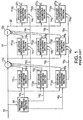
- Fig. 1 shows the structure of a conventional CDMA receiver for carrying out interference removal in a multistage fashion.
- the CDMA receiver comprises a reception timing detecting section 10 for detecting reception timings of three users and, in correspondence to the reception timings, interference estimating sections in each stage.
- the interference estimating sections includes first-through third-stage interference estimating sections 11 11 through 11 13 corresponding to the reception timing of a first user, first- through third-stage interference estimating sections 11 21 through 11 23 corresponding to the reception timing of a second user, and first- through third-stage interference estimating sections 11 31 to 11 33 corresponding to the reception timing of a third user.
- the CDMA receiver further comprises residual signal producing sections 12 1 and 12 2 .
- a multiplexed signal 13 received by the CDMA receiver is supplied to the reception timing detecting section 10, the first-stage interference estimating sections 11 11 through 11 31 , and the residual signal producing section 12 1 .
- the multiplexed signal 13 is a frame signal composed of a plurality of slots. At a predetermined position in the frame, a pilot symbol as predetermined pattern data is added before or after an information symbol of a predetermined length.
- the reception timing detecting section 10 detects the pilot symbol added to the multiplexed signal 13 to detect data reception timings of desired users.
- the reception timings thus detected are supplied as reception timings 14 1 through 14 3 to the first-stage interference estimating sections 11 11 through 11 31 , the second-stage interference estimating sections 11 12 through 11 32 , and the third-stage interference estimating sections 11 13 through 11 33 individually for the users, i.e., individually for the reception timings.
- the first-stage interference estimating sections 11 11 through 11 31 multiply the multiplexed signal 13 by spread codes assigned to the individual users to extract data signals of the desired users, respectively.
- the data signals thus extracted are supplied as user signals 15 1 through 15 3 to the second-stage interference estimating sections 11 12 through 11 32 in a subsequent stage, respectively.
- the first-stage interference estimating sections 11 11 through 11 31 multiply the extracted user data signals again by the spread codes assigned to the users.
- signal components of the users contained in the multiplexed signal 13 are reproduced to obtain reproduction signals 16 1 through 16 3 which are supplied to the residual signal producing section 12 1 .
- the residual signal producing section 12 1 is supplied with the multiplexed signal 13 in addition to the reproduction signals 16 1 through 16 3 and produces a residual signal 17 obtained by subtracting the reproduction signals 16 1 through 16 3 from the multiplexed signal 13.
- the residual signal 17 is used as an input signal to be subjected to interference removal in the second stage.
- the residual signal 17 is supplied to the second-stage interference estimating sections 11 12 through 11 32 and the residual signal producing section 12 2 .
- the second-stage interference estimating sections 11 12 through 11 32 multiply the residual signal 17 supplied thereto by the spread codes individually assigned to the users to despread the residual signal.
- Resultant signals (or despread signals) are weak in signal level. Therefore, in order to minimize errors produced in transmission-path estimation required upon demodulation, the user signals 15 1 through 15 3 supplied from the first-stage interference estimating sections 11 11 through 11 31 are added to the resultant signals to produce added user signals increased in ratio of the signal components of the desired users. Thus, data signals of the desired users are extracted.
- the data signals thus extracted are supplied as user signals 18 1 through 18 3 to the third-stage interference estimating sections 11 13 through 11 33 in a subsequent stage, respectively.
- the second-stage interference estimating sections 11 12 through 11 32 subtract, from the user data signals extracted thereat as demodulation signals, signal components corresponding to the user signals 15 1 through 15 3 previously added and multiply results of extraction again by the spread codes assigned to the users, respectively.
- signal components of the relevant users contained in the residual signal 17 are reproduced as reproduction signals 19 1 through 19 3 which are supplied to the residual signal producing section 12 2 .
- the residual signal producing section 12 2 is supplied with the residual signal 17 in addition to the reproduction signals 19 1 through 19 3 and produces a residual signal 20 obtained by subtracting the reproduction signals 19 1 through 19 3 from the residual signal 17.
- the residual signal 20 is used as an input signal to be subjected to interference removal in the third stage.
- the third-stage interference estimating sections 11 13 through 11 33 extract desired user signals for the residual signal 20 and produce demodulation signals 21 1 through 21 3 of the desired users corresponding to the user signals 16 1 through 16 3 and 18 1 through 18 3 produced by the first- and the second-stage interference estimating sections 11 11 through 11 31 and 11 12 through 11 32 , respectively.
- the residual signal 20 approaches nearer to zero than the residual signal 17 so that the third-stage interference estimating sections 11 13 through 11 33 produce the demodulation signals 21 1 through 21 3 from the added user signals after the interference is removed at maximum, respectively.
- JP-A Japanese Unexamined Patent Publication
- H10-190494 "INTERFERENCE CANCELLER AND CHANNEL ESTIMATION”.
- a CDMA receiver to which this invention is applicable is for receiving, as a reception signal, a signal given by subjecting a data signal comprising predetermined pattern data to spread modulation by the use of a spread code.
- the receiver comprises:
- the reception timing determining means determines the reception timing such that the maximum value of the correlation value data exceeds a predetermined first threshold value and that the signal-to-interference ratio exceeds a predetermined second threshold value when the correlation value data have the maximum value.
- the signal-to-interference ratio calculating means may calculate the signal-to-interference ratio from the reception signal and the correlation value data produced by the correlation value data producing means.
- the receiver comprises:
- Fig. 2 shows the structure of a CDMA receiver according to a first embodiment of this invention.
- the CDMA receiver in the first embodiment is a CDMA receiver utilizing a multistage-type interference removing technique of repeating interference removal in three stages for three users. However, the number of users and the number of stages are not restricted at all.
- the CDMA receiver in the first embodiment comprises a reception timing detecting section 30 for detecting reception timings for three users, respectively, and interference estimating sections in each stage in correspondence to the reception timings.
- the interference estimating sections include first- through third-stage interference estimating sections 31 11 through 31 13 corresponding to the reception timing of the first user, first- through third-stage interference estimating sections 31 21 through 31 23 corresponding to the reception timing of the second user, and first-through third-stage interference estimating sections 31 31 through 31 33 corresponding to the reception timing of the third user.
- the CDMA receiver further comprises residual signal producing sections 32 1 and 32 2 .
- a multiplexed signal 33 received by the CDMA receiver is supplied to the reception timing detecting section 30, the first-stage interference estimating sections 31 11 through 31 31 , and the residual signal producing section 32 1 .
- the multiplexed signal 33 is a frame signal composed of a plurality of slots. At a predetermined slot of the slots in the frame signal, a pilot symbol as predetermined pattern data is added before (or after) an information symbol (as information data) of a predetermined length.
- the reception timing detecting section 30 is supplied with SIR information 34 1 through 34 3 from the first-stage interference estimating sections 31 11 through 31 31 , respectively.
- the SIR information 34 1 through 34 3 are SIRs measured in correspondence to the reception timings.
- the reception timing detecting section 30 corrects the data reception timings detected for the desired users with reference to the SIR information X through 34 3 corresponding thereto.
- Reception timing information 35 1 through 35 3 thus corrected are supplied to the first-stage interference estimating sections 31 11 through 31 31 , the second-stage interference estimating sections 31 12 through 31 32 , and the third-stage interference estimating sections 31 13 through 31 33 .
- the first-stage interference estimating sections 31 11 through 31 31 are adapted to produce reception timings obtained by preliminarily compensating a processing delay in the reception timing detecting section 30 and other internal propagation delays, and to correct reception timings as demodulation timings with reference to the reception timing information 35 1 through 35 3 supplied thereto for individual users.
- the first-stage interference estimating sections 31 11 through 31 31 carry out demodulation of the multiplexed signal 33 in correspondence to the users by multiplying the multiplexed signal 33 by spread codes assigned to the individual users.
- the demodulated data are supplied as reception data 36 1 through 36 3 of the desired users to the second-stage interference estimating sections 31 12 through 31 32 as a next stage.
- the first-stage interference estimating sections 31 11 through 31 31 again uses the spread codes assigned to the individual users to reproduce signal components of the relevant users contained in the multiplexed signal 33.
- the signal components thus reproduced are delivered as reproduction signals 37 1 through 37 3 to the residual signal producing section 32 1 .
- the residual signal producing section 32 1 is supplied with the multiplexed signal 33 in addition to the reproduction signals 37 1 through 37 3 and produces a residual signal 38 obtained by subtracting the reproduction signals 37 1 through 37 3 from the multiplexed signal 33.
- the residual signal 38 is used as an input signal to be subjected to interference removal in the second stage.
- the residual signal 38 is supplied to the second-stage interference estimating sections 31 12 through 31 32 and the residual signal producing section 32 2 .
- the second-stage interference estimating sections 31 12 through 31 32 carry out despreading by multiplying the residual signal 38 supplied thereto by the spread codes individually assigned. Resultant signals have a small signal level. Therefore, in order to minimize errors produced in transmission-path estimation required upon demodulation, the reception data 36 1 through 36 3 supplied from the first-stage interference estimating sections 31 11 through 31 31 are added thereto to produce added user signals increased in ratio of signal components of the desired users. Thus, data signals of the desired users are extracted.
- the data signals thus extracted are supplied as reception data 39 1 through 39 3 to the third-stage interference estimating sections 31 13 through 31 33 .
- the second-stage interference estimating sections 31 12 through 31 32 subtract, from the extracted reception data demodulated data corresponding to the reception data 36 1 through 36 3 previously added and then multiply user data signals again by the spread codes assigned to the users, respectively.
- the signal components of the relevant users contained in the residual signal 38 are reproduced.
- These signal components are supplied as reproduction signals 40 1 through 40 3 to the residual signal producing section 32 2 .
- the residual signal producing section 32 2 is supplied with the residual signal 38 and produces a residual signal 41 obtained by subtracting the reproduction signals 40 1 through 40 3 from the residual signal 38.
- the residual signal 41 is used as an input signal to be subjected to interference removal in the third stage.
- the third-stage interference estimating sections 31 13 through 31 33 extract desired user signals for the residual signal 41 and produce demodulation signals 42 1 through 42 3 of the desired users corresponding to the reception data 36 1 through 36 3 and 39 1 through 39 3 produced by the first- and the second-stage interference estimating sections 31 11 through 31 31 and 31 12 through 31 32 , respectively.
- the residual signals 38 and 41 successively approach zero so that the third-stage interference estimating sections 31 13 through 31 33 produce the demodulation signals 42 1 through 42 3 from the added user signals after the interference is removed at maximum, respectively.
- Fig. 3 shows the characteristic part of the first-stage interference estimating sections of the CDMA receiver in Fig. 2 according to the first embodiment.
- the first-stage interference estimating sections 31 11 through 31 31 are separately illustrated in correspondence to the reception timings detected for the individual users for which simultaneous demodulation is possible.
- these sections are integrated in Fig. 3 into a first-stage interference estimating section 44 1 .
- the first-stage interference estimating section 44 1 has demodulation processing units 45 1 through 45 3 and re-spreading units 46 1 through 46 3 for the reception timings, respectively, and comprises a RAKE combining unit 47 1 and a reproduction signal producing unit 48 1 in common to all of the reception timings.
- the demodulation processing units 45 1 through 45 3 are similar in structure to one another.
- the re-spreading units 46 1 through 46 3 are similar in structure to one another. Although three timings are herein illustrated, the number of timings is not restricted in principle as far as the constraint in mounting is eliminated.
- the demodulation processing unit 45 1 and the re-spreading unit 46 1 will be described among these demodulation processing units and these re-spreading units.
- the demodulation processing unit 45 1 comprises a demodulating portion 49 1 for demodulating an input signal, a reception timing producing portion 50 1 for producing a demodulation timing of the demodulating portion 49 1 , and an SIR information producing portion 51 1 for measuring an SIR of the input signal to produce SIR information.
- the demodulating portion 49 1 comprises a despreading part 53 1 and a transmission-path estimating part 54 1 .
- the demodulation processing unit 45 1 is supplied with the multiplexed signal 33.
- the despreading part 53 1 of the demodulating portion 49 1 multiplies the multiplexed signal by the spread code of a predetermined user to extract a desired user signal.
- the transmission-path estimating part 54 1 calculates transmission-path characteristic information by the use of a pilot symbol known to be preliminarily contained in the reception signal and compensates despread data with reference to the transmission-path characteristic information. Such demodulation by the demodulating portion 49 1 is carried out in synchronism with the reception timing produced by the reception timing producing portion 50 1 .
- the reception timing producing portion 50 1 produces the reception timing obtained by preliminarily compensating the processing delay of the reception timing detecting section 30 or other internal propagation delays, and further corrects the reception timing with reference to the reception timing information 35 1 . For example, the reception timing produced as mentioned above preliminarily considering the delay is used as abase and corrected with reference to the reception timing information 35 1 .
- the SIR information producing portion 51 1 calculates a signal-to-interference ratio for a signal component which is the despread data despread by the demodulating portion 49 1 and for an interference component which is a remaining component of the reception signal other than the signal component, and produces the SIR information representative of the ratio.
- the SIR information is supplied to the RAKE combining unit 48 1 and, in the first-stage interference estimating section 44 1 , further to the reception timing detecting section 30.
- the RAKE combining unit 47 1 is supplied with the despread data despread by the demodulating portion 49 1 and carries out maximum ratio synthesis with reference to the SIR information produced by the SIR information producing portion 51 1 for the individual reception timings. Specifically, weighted synthesis given by "SIR 1 x S 1 + SIR 2 x S 2 + SIR 3 x S 3 " is carried out where S 1 through S 3 and SIR 1 through SIR 3 represent the despread data and the SIR information of the individual users, respectively.
- the synthesized output of the RAKE combining unit 47 1 is supplied to the re-spreading units 46 1 through 46 3 .
- the re-spreading unit 46 1 comprises a spreading portion 55 1 .
- the synthesized output of the RAKE combining unit 47 1 supplied to the re-spreading unit 46 1 is directly outputted as the reception data 36 1 .
- the spreading portion 55 1 multiplies the synthesized output again by the spread code corresponding to each individual user to produce a spread signal.
- the spread signal is supplied as the reproduction signal 37 1 to the reproduction signal producing unit 48 1 .
- the reproduction signal producing unit 48 1 is supplied with the reproduction signals 37 1 through 37 3 produced for the individual reception timings and combines these signals to reproduce a signal with the individual timings taken into account, as is equivalent to the multiplexed signal 33.
- the reproduction signal 37 herein reproduced is delivered to the residual signal producing section 32 1 .
- the residual signal producing section 32 1 produces the residual signal 38 by subtracting from the multiplexed signal 33 the reproduction signal 37 with the individual timings taken into account.
- the first-stage interference estimating section 44 1 corrects the demodulation timing with reference to the reception timing information and produces the demodulated data and the reproduced data.
- the second- and the third-stage interference estimating sections 44 2 and 44 3 are similar in structure and different from the first-stage interference estimating section 44 1 in that the demodulated data of the preceding stage are supplied and correction of the demodulation timings is not carried out.
- Fig. 4 shows the characteristic part of the second-stage interference estimating sections of the CDMA receiver in Fig. 2 according to the first embodiment.
- the second-stage interference estimating sections 31 12 through 31 32 are separately illustrated in correspondence to the reception timings detected for the individual users for which simultaneous demodulation is possible.
- these sections are integrated in Fig. 4 into a second-stage interference estimating section 44 2 .
- the second-stage interference estimating section 44 2 has demodulation processing units 56 1 through 56 3 and re-spreading units 57 1 through 57 3 for the reception timings, respectively, and comprises a RAKE combining unit 58 1 and a reproduction signal producing unit 59 1 in common to all of the reception timings.
- the demodulation processing units 56 1 through 56 3 are substantially similar in structure to one another.
- the re-spreading units 57 1 through 57 3 are similar in structure to one another.
- the demodulation processing unit 56 1 comprises a demodulating portion 60 1 for demodulating an input signal, an SIR information producing portion 61 1 for measuring an SIR of the input signal to produce SIR information, and an adder portion 62 1 .
- the demodulating portion 60 1 comprises a despreading part 63 1 and a transmission-path estimating part 64 1 .
- the demodulation processing unit 56 1 further comprises a reception timing producing portion 65 1 for producing a demodulation timing of the demodulating portion.
- the second-stage interference estimating section 44 2 is substantially similar in structure to the first-stage interference estimating section 44 1 . Therefore, different parts alone will be described.
- the demodulation processing unit 56 1 is supplied with the residual signal 38 and the reception timing produced by the reception timing producing portion 65 1 .
- Demodulation by the demodulating portion 60 1 is carried out in synchronism with the reception timing produced by the reception timing producing portion 65 1 .
- the reception timing producing portion 65 1 produces the reception timing obtained by preliminarily compensating the processing delay of the reception timing detecting section 30 and other internal propagation delays, and further corrects the reception timing with reference to the reception timing information 35 1 .
- the reception timing produced preliminarily taking the delay into account is used as a base and corrected with reference to the reception timing information 35 1 .
- the demodulating portion 60 1 of the demodulating processing unit 56 1 carries out despreading in synchronism with the spread code preliminarily assigned to the user to extract a desired user signal.
- the despread data despread by the demodulating portion 60 1 are supplied to the adder portion 62 1 .
- the adder portion 62 1 is supplied from the first-stage interference estimating section 44 1 with the reception data 36 1 corresponding to the reception timing and adds the reception data 36 1 to the despread data. This increases the ratio of the signal component of each individual user contained in the weak residual signal 38 supplied to the second-stage interference estimating section 44 2 as the input signal to be subjected to interference removal, and enhances the accuracy of the demodulation signal.
- the result of addition in the adder portion 62 1 is supplied to the RAKE combining unit 58 1 .
- the re-spreading unit 57 1 comprises a subtracter portion 66 1 and a spreading portion 67 1 .
- the re-spreading unit 57 1 directly outputs, as the reception data 39 1 , the synthesized output obtained by maximum ratio synthesis in the RAKE combining unit 58 1 .
- the subtracter portion 66 1 of the re-spreading unit 57 1 subtracts the despread signal 68 1 from the maximum synthesized ratio output.
- the result of subtraction is supplied to the spreading portion 67 1 .
- the spreading portion 67 1 multiplies the subtraction result by the spread code corresponding to each individual user to produce a spread signal.
- the spread signal is supplied as the reproduction signal 40 1 to the reproduction signal producing unit 59 1 .
- the reproduction signal producing unit 59 1 is supplied with the reproduction signals 40 1 through 40 3 produced for the individual reception timings and combines these signals to reproduce a signal with the individual timings taken into account, as is equivalent to the residual signal 38.
- the reproduction signal 40 herein reproduced is delivered to the residual signal producing section 32 2 .
- the residual signal producing section 32 2 produces the residual signal 41 by subtracting, from the residual signal 38, the reproduction signal 40 with the individual reception timings taken into account.
- the second-stage interference estimating section 44 2 corrects the reception data 36 1 through 36 3 from the first stage and delivers the corrected data to the third stage.
- a combination of the third-stage interference estimating sections 31 13 through 31 33 similarly operates to obtain the reception data 42 1 through 42 3 for the individual users.
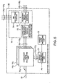
- Fig. 5 shows the characteristic part of the reception timing detecting section 30 of the CDMA receiver in the first embodiment.
- the reception timing detecting section 30 has correlation value calculating units 70 1 through 70 3 for the individual reception timings and comprises a spread code delay generating unit 71, a spread code producing unit 72, and a reception timing calculating unit 73 in common to all of the reception timings.
- the correlation value calculating units 70 1 through 70 3 are provided for the three timings, the number of timings is not restricted in principle as far as the constraint in mounting is eliminated.
- the reception timing calculating unit 73 comprises an SIR calculating portion 74, a correlation value data averaging portion 75, and a reception timing determining portion 76.
- the spread code producing unit 72 produces the predetermined spread bodes for the individual users.
- the spread code delay generating unit 71 multiplies the spread codes of the individual users produced by the spread code producing unit 72 by the pilot symbol PS as the predetermined (or fixed) pattern data, For each user, the length of the pilot symbol is extracted from the spread code having a predetermined pattern length and is used in multiplication. By shifting the position of extracting the spread code over the width of a predetermined sampling period within a range of a reception timing detectable period, predetermined signal reproduction signals 77 1 through 77 3 are obtained with the spread codes delayed.
- the correlation value calculating units 70 1 through 70 3 multiply the multiplexed signal 33 by the predetermined signal reproduction signals 77 1 through 77 3 supplied thereto, respectively, to calculate correlation data 78 1 through 78 3 as cross-correlation values therebetween within the reception timing detectable period.
- the correlation data 78 1 through 78 3 are cross-correlation values corresponding in number to sampling times.
- the correlation value data averaging portion 75 of the reception timing calculating unit 73 carries out averaging over a predetermined time duration for each sampling and produces a correlation value table.
- Fig. 6 shows a table structure of the correlation value table 79 produced by the correlation value data averaging portion 75.
- the correlation value table 79 stores sampling times 80 and correlation value levels 81 corresponding thereto.
- the correlation value data averaging portion 75 carries out averaging upon the correlation data 78 1 through 78 3 produced by the correlation value calculating units 70 1 through 70 3 over the predetermined time duration for each sampling. For example, it is assumed that N times of sampling is possible within the reception timing detectable period. Then, correlation data average values LV 0 through LV N taken over the predetermined time duration for the sampling times T 1 through T N , respectively, are stored in the correlation value table 79 in correspondence to the sampling times.
- the SIR calculating portion 74 calculates, by linear interpolation and averaging, the SIR information at the sampling times within the predetermined time range between time instants before and after the reception timing.
- the SIR information thus calculated is stored in an SIR information table.
- Fig. 7 shows a table structure of the SIR information table 82 produced by the SIR calculating portion 74.
- the SIR information table 82 stores the SIR information 84 as interpolated values corresponding thereto. It is assumed that the reception timing is located at a position T m on a time axis.
- the SIR information is calculated by linear interpolation and averaging from the SIR information 34 1 through 34 3 corresponding in number to the reception timings and stored as SIR 0 through SIR M .
- the reception timing determining portion 76 of the reception timing calculating unit 73 determines the reception timing for demodulation with reference to the information stored in the correlation value table produced by the correlation value data averaging portion 75 and the SIR information table produced by the SIR calculating portion 74.
- Fig. 8 shows the content of reception timing determination at the reception timing determining portion 76.
- the reception timing determining portion 76 refers to the correlation value table 79 illustrated in Fig. 6 and retrieves a particular sampling time having a maximum correlation value level (step S85). Then, judgement is made about whether or not the maximum correlation value level is not smaller than a predetermined first threshold value (step S86). If it is judged that the maximum correlation value level is not smaller than the first threshold value (Y in step S86), the SIR information table 82 illustrated in Fig. 7 is searched from the sampling time corresponding to the maximum correlation value level to retrieve the interpolated sampling time corresponding thereto.
- the reception timing is preliminarily known upon preparation of the SIR information table, it is easy to establish the correspondence between the interpolated sampling time 83 of the SIR information within the predetermined range and the sampling time 80 in Fig. 6. Therefore, the interpolated sampling time 83 corresponding to the sampling time is identified and the SIR information stored In correspondence to the interpolated sampling time can be retrieved (S87). If it is judged in the step S86 that the first threshold value is not exceeded (N in step S86), the operation returns to the step S85 to retrieve the next reception timing.
- step S88 judgement is made about whether or not the SIR information retrieved in the step S87 is not smaller than a predetermined second threshold value (step S88). If it is judged that the SIR information is not smaller than the second threshold value (Y in step S88), the timing in question is determined as the reception timing (step S89). If it is judged in the step S88 that the second threshold value is not exceeded (N in the step S88), the operation returns to the step S85 to retrieve the next reception timing. Finally, judgement is made about completion of retrieval, i.e., whether or not the reception timings of a required number have been determined or whether or not the correlation value table has been completely retrieved. If no further retrieval is required (Y in step S90), a series of operations are finished (END). On the other hand, if any further retrieval is required, the operation returns to the step S85 to retrieve the next reception timing.
- the SIR information table including interpolation before and after the reception timing is prepared by the use of the SIR information measured by the first-stage interference estimating section 44 1 for each individual user. Furthermore, for the reception signal, the correlation value table is provided to store the correlation value with the pilot symbol to be used as the reception timing in correspondence to each sampling time within a range of the reception timing detectable period. Thus, correction into an optimum reception timing is made. Therefore, even in case where the multistage interference removal of a multi-user type is carried out, it is possible to eliminate the influence of the interference component from the reception timing and to carry out interference removal with reference to the accurate reception timing.
- the CDMA receiver according to the first embodiment is applied to the multistage interference removal but this invention is not restricted thereto.
- illustration is made of a CDMA receiver which is not applied to the multistage interference removal.
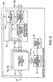
- Fig. 9 shows a characteristic part of a reception timing detecting section of the CDMA receiver according to the second embodiment of this invention. Similar parts are designated by like reference numerals as those of the reception timing detecting section 30 in Fig. 2 according to the first embodiment and the description thereof will appropriately be omitted.
- the reception timing detecting section 100 in the second embodiment has correlation value calculating units 70 1 through 70 3 for individual reception timings and comprises a spread code delay generating unit 71, a spread code producing unit 72, and a reception timing calculating unit 101 in common to all of the reception timings.
- the reception timing calculating unit 101 comprises an SIR calculating portion 102, a correlation value data averaging portion 75, and a reception timing determining portion 76.
- the spread code producing unit 72 produces the predetermined spread codes for the individual users.
- the spread code delay generating unit 71 multiplies the spread codes of the individual users produced by the spread code producing unit 72 by the pilot symbol PS as the predetermined pattern data. For each user, the length of the pilot symbol is extracted from the spread code having a predetermined pattern length and is used in multiplication. By shifting the position of extracting the spread code over the width of a predetermined sampling period within a range of a reception timing detectable period, predetermined signal reproduction signals 77 1 through 77 3 are obtained with the spread codes delayed.
- the correlation value calculating units 70 1 through 70 3 multiply the multiplexed signal 33 by the predetermined signal reproduction signals 77 1 through 77 3 supplied thereto, respectively, to calculate correlation data 78 1 through 78 3 as cross-correlation values therebetween within the reception timing detectable period.
- the correlation data 78 1 through 78 3 are cross-correlation values corresponding in number to sampling times.
- the correlation value data averaging portion 75 of the reception timing calculating unit 73 carries out averaging over a predetermined time duration for each sampling and produces a correlation value table illustrated in Fig. 6.
- the SIR calculating portion 102 calculates SIRs at all sampling points from the multiplexed signal 33 and the correlation value data 78 1 through 78 3 corresponding in number to the reception timings.
- the SIRS are subjected to linear interpolation and averaging for a predetermined period to calculate the SIR information at sampling times in a predetermined time range before and after the reception timing.
- the SIR information thus calculated is stored in a SIR information table illustrated in Fig. 7, in the manner similar to the first embodiment
- the reception timing determining portion 76 of the reception timing calculating unit 101 determines the reception timing for demodulation with reference to the information stored in the correlation value table produced by the correlation value data averaging portion 75 and the SIR information table produced by the SIR calculating portion 102.
- the operation is similar to that illustrated in Fig. 8 and will not be described.
- the reception timing thus determined may be outputted as the reception timing information for making the reception timing producing section produce the accurate reception timing as described in the first embodiment or may be delivered directly as the reception timing to a demodulator not illustrated in the figure.
- the mode of output is not restricted.
- the reception timing detecting section produces the SIR information table from the multiplexed signal and the correlation value data. Therefore, it is unnecessary for the first-stage interference estimating section to refer to the SIR information as in the first embodiment. This contributes to a reduction in size of the receiver.
- the above-mentioned reception timing detecting section can notify the accurate reception timing not only to the CDMA receiver using the above-mentioned multistage interference removal but also to other types of receivers.
- description has been directed to application to the multistage interference removing technique of repeating the interference removal for three users in three stages.
- the number of users and the number of stages are not restricted at all.
- the demodulation timing of the reception multiplexed signal is corrected with reference to the correlation value detected as the reception timing and the SIR in the actual demodulation signal. Therefore, even if the SIR is low, the optimum reception timing can be detected so that the reception quality is improved. In addition, it is possible to lower the SIR required to obtain a predetermined reception quality. Therefore, the transmission power of a mobile terminal in a CDMA mobile communication system can be lowered. This contributes to a reduction in size of the terminal and to low the power consumption. Since the transmission power at each user is lowered, it is possible to increase the number of users for which multiplexing in a same frequency is possible.
Landscapes
- Engineering & Computer Science (AREA)
- Computer Networks & Wireless Communication (AREA)
- Signal Processing (AREA)
- Noise Elimination (AREA)
- Mobile Radio Communication Systems (AREA)
- Synchronisation In Digital Transmission Systems (AREA)
Abstract
Description
- This invention relates to a receiver of a code-division multiple access system and, in particular, to a receiver of a code-division multiple access system intended to improve a reception quality.
- In a conventional mobile communication system such as a mobile telephone, use has been made of a multiplexing system such as a time division multiple access (TDMA) system or a frequency division multiple access (FDMA) system. However, in response to a growing demand for effective use of frequencies following an increase in number of subscribers and for multimedia communications, attention is directed to a code division multiple access (hereinafter abbreviated to CDMA) system as a multiplexing system for a next-generation mobile telephone. The CDMA system is a technique for simultaneously carrying out a plurality of communications by the use of signals in a same frequency band by means of the spread spectrum technique. In a CDMA mobile communication system using the above-mentioned technique, a plurality of users occupy a same frequency and a same time and modulate communication data by the use of spread codes assigned to the users to identify the users. The spread codes of the users are orthogonal to one another. Therefore, at a receiving side, a multiplexed signal obtained by multiplexing all user's communication data is multiplied by a spread code used by each user in a same phase so as to extract communication data of a desired user.
- In the CDMA mobile communication system, a communication quality is determined by orthogonality of communication data signals of all users multiplexed in the same frequency. Practically, however, due to variation in a propagation condition, the orthogonality can not completely be maintained. Therefore, when the signal of the desired user is demodulated, a signal component of another user is undesiredly contained to result in deterioration in signal quality. In order to avoid the deterioration in signal quality, the receiving side measures a ratio between a signal reception level and an interference reception level for the desired user and requests a transmitting side to change transmission power so as to satisfy a predetermined ratio. In this approach, a transmission level is increased at the transmitting side in order to maintain a predetermined signal-to-interference ratio (hereinafter abbreviated to SIR) at a CDMA receiver in the CDMA mobile communication system. However, increase in transmission level prevents the reduction in power consumption at a terminal and the improvement in degree of multiplexing into the same frequency. In order to solve the above-mentioned problem, attention is directed to an interference removing technique. In the interference removing technique, an interference wave, i.e., a signal component other than that of a desired user is removed from a communication data signal received. Thus, it is possible to improve a reception signal quality even in a low SIR condition.
- Hereinafter, description will be made of a CDMA receiver using the interference removing technique. Herein, it is assumed that the CDMA receiver performs an interference removing operation of a multistage type in which interference removal is repeatedly carded out in three stages for three users.
- Fig. 1 shows the structure of a conventional CDMA receiver for carrying out interference removal in a multistage fashion. The CDMA receiver comprises a reception
timing detecting section 10 for detecting reception timings of three users and, in correspondence to the reception timings, interference estimating sections in each stage. The interference estimating sections includes first-through third-stage interference estimating sections 1111 through 1113 corresponding to the reception timing of a first user, first- through third-stage interference estimating sections 1121 through 1123 corresponding to the reception timing of a second user, and first- through third-stage interference estimating sections 1131 to 1133 corresponding to the reception timing of a third user. The CDMA receiver further comprises residual signal producing sections 121 and 122. - A multiplexed
signal 13 received by the CDMA receiver is supplied to the receptiontiming detecting section 10, the first-stage interference estimating sections 1111 through 1131, and the residual signal producing section 121. The multiplexedsignal 13 is a frame signal composed of a plurality of slots. At a predetermined position in the frame, a pilot symbol as predetermined pattern data is added before or after an information symbol of a predetermined length. The receptiontiming detecting section 10 detects the pilot symbol added to the multiplexedsignal 13 to detect data reception timings of desired users. The reception timings thus detected are supplied as reception timings 141 through 143 to the first-stage interference estimating sections 1111 through 1131, the second-stage interference estimating sections 1112 through 1132, and the third-stage interference estimating sections 1113 through 1133 individually for the users, i.e., individually for the reception timings. In synchronism with the reception timings 141 through 143 detected by the receptiontiming detecting section 10 for the individual users, the first-stage interference estimating sections 1111 through 1131 multiply the multiplexedsignal 13 by spread codes assigned to the individual users to extract data signals of the desired users, respectively. The data signals thus extracted are supplied as user signals 151 through 153 to the second-stage interference estimating sections 1112 through 1132 in a subsequent stage, respectively. In addition, the first-stage interference estimating sections 1111 through 1131 multiply the extracted user data signals again by the spread codes assigned to the users. Thus, signal components of the users contained in the multiplexedsignal 13 are reproduced to obtain reproduction signals 161 through 163 which are supplied to the residual signal producing section 121. The residual signal producing section 121 is supplied with themultiplexed signal 13 in addition to the reproduction signals 161 through 163 and produces aresidual signal 17 obtained by subtracting the reproduction signals 161 through 163 from themultiplexed signal 13. Theresidual signal 17 is used as an input signal to be subjected to interference removal in the second stage. - The
residual signal 17 is supplied to the second-stage interference estimating sections 1112 through 1132 and the residual signal producing section 122. In synchronism with the reception timings 141 through 143 detected by the receptiontiming detecting section 10 for the individual users, the second-stage interference estimating sections 1112 through 1132 multiply theresidual signal 17 supplied thereto by the spread codes individually assigned to the users to despread the residual signal. Resultant signals (or despread signals) are weak in signal level. Therefore, in order to minimize errors produced in transmission-path estimation required upon demodulation, the user signals 151 through 153 supplied from the first-stage interference estimating sections 1111 through 1131 are added to the resultant signals to produce added user signals increased in ratio of the signal components of the desired users. Thus, data signals of the desired users are extracted. The data signals thus extracted are supplied as user signals 181 through 183 to the third-stage interference estimating sections 1113 through 1133 in a subsequent stage, respectively. In addition, the second-stage interference estimating sections 1112 through 1132 subtract, from the user data signals extracted thereat as demodulation signals, signal components corresponding to the user signals 151 through 153 previously added and multiply results of extraction again by the spread codes assigned to the users, respectively. Thus, signal components of the relevant users contained in theresidual signal 17 are reproduced as reproduction signals 191 through 193 which are supplied to the residual signal producing section 122. The residual signal producing section 122 is supplied with theresidual signal 17 in addition to the reproduction signals 191 through 193 and produces aresidual signal 20 obtained by subtracting the reproduction signals 191 through 193 from theresidual signal 17. Theresidual signal 20 is used as an input signal to be subjected to interference removal in the third stage. - Likewise, the third-stage interference estimating sections 1113 through 1133 extract desired user signals for the
residual signal 20 and produce demodulation signals 211 through 213 of the desired users corresponding to the user signals 161 through 163 and 181 through 183 produced by the first- and the second-stage interference estimating sections 1111 through 1131 and 1112 through 1132, respectively. In this event, theresidual signal 20 approaches nearer to zero than theresidual signal 17 so that the third-stage interference estimating sections 1113 through 1133 produce the demodulation signals 211 through 213 from the added user signals after the interference is removed at maximum, respectively. - The above-mentioned technique related to the CDMA receiver is disclosed, for example, in Japanese Unexamined Patent Publication (JP-A) No. H10-190494 "INTERFERENCE CANCELLER AND CHANNEL ESTIMATION".
- However, in the conventional CDMA receiver already proposed, interference is not removed from the multiplexed signal itself supplied to the reception timing detecting section. Therefore, the reception timings of the desired users are detected from the reception signal containing interference waves at a great ratio. As a consequence, it is difficult to detect accurate reception timings. Furthermore, since the interference of the reception signal is removed with reference to such inaccurate reception timings, the reception quality is deteriorated to cancel the effect of interference removal.
- It Is therefore an object of this invention to provide a CDMA receiver which enables detection of accurate reception timings even in a condition that an SIR is low.
- A CDMA receiver to which this invention is applicable is for receiving, as a reception signal, a signal given by subjecting a data signal comprising predetermined pattern data to spread modulation by the use of a spread code.
- According to an aspect of this invention, the receiver comprises:
- correlation value data producing means for producing correlation value data obtained by multiplying the reception signal by the spread code and the predetermined pattern data;
- signal-to-interference ratio calculating means for calculating a signal-to-interference ratio of said reception signal; and
- reception timing determining means for determining a reception timing of said predetermined pattern data in response to said correlation value data and said signal-to-interference ratio.
-
- Preferably, the reception timing determining means determines the reception timing such that the maximum value of the correlation value data exceeds a predetermined first threshold value and that the signal-to-interference ratio exceeds a predetermined second threshold value when the correlation value data have the maximum value.
- The signal-to-interference ratio calculating means may calculate the signal-to-interference ratio from the reception signal and the correlation value data produced by the correlation value data producing means.
- According to another aspect of this invention, the receiver comprises:
- correlation value data producing means for producing, at each sampling point within a predetermined time range, correlation value data obtained by multiplying the reception signal by the spread code and the predetermined pattern data;
- correlation value data memorizing means for memorizing, in correspondence to the above-mentioned each sampling point, the correlation value data produced by the correlation value data producing means;
- signal-to-interference ratio calculating means for calculating a signal-to-interference ratio of the reception signal;
- signal-to-interference ratio memorizing means for producing an interpolating signal-to-interference ratio for the signal-to-interference ratio calculated by the signal-to-interference ratio calculating means for each sampling point within the time range based on a reception timing at which the signal-to-interference ratio is calculated and for memorizing the interpolating signal-to-interference ratios in correspondence to the above-mentioned each sampling point;
- retrieving means for retrieving maximum correlation value data among the correlation value data memorized in the correlation value data memorizing means;
- correlation value data judging means for judging whether or not the maximum correlation value data retrieved by the retrieving means exceed a predetermined first threshold value;
- ratio judging means for judging, when the correlation value data judging means judges that the maximum correlation value data exceed the first threshold value, whether or not a particular signal-to-interference ratio memorized in the signal-to-interference ratio memorizing means in correspondence to a particular sampling point of the maximum correlation value data exceeds a predetermined second threshold value; and
- reception timing determining means for determining, when the ratio judging means judges that the particular signal-to-interference ratio exceeds the second threshold value, a reception timing corresponding to the particular sampling point as a reception timing of the predetermined pattern data.
-
-
- Fig. 1 is a view showing the structure of a conventional CDMA receiver;
- Fig. 2 is a view showing the structure of a CDMA receiver according to a first embodiment of this invention;
- Fig. 3 is a block diagram showing a characteristic part of the structure of a first-stage interference estimating section in the first embodiment
- Fig. 4 is a block diagram showing a characteristic part of the structure of a second-stage interference estimating section in the first embodiment;
- Fig. 5 is a block diagram showing a characteristic part of the structure of a reception timing detecting section in the CDMA receiver according to the first embodiment;
- Fig. 6 is a view for describing a table structure of a correlation value table in the first embodiment;
- Fig. 7 is a view for describing a table structure of an SIR information table in the first embodiment;
- Fig. 8 is a flow chart showing the content of determination of a reception timing in a reception timing determining portion in the first embodiment; and
- Fig. 9 is a block diagram showing a characteristic part of the structure of a reception timing detecting section of a CDMA receiver according to a second embodiment.
-
- Now, this invention will be described in detail in conjunction with several embodiments.
- Fig. 2 shows the structure of a CDMA receiver according to a first embodiment of this invention. The CDMA receiver in the first embodiment is a CDMA receiver utilizing a multistage-type interference removing technique of repeating interference removal in three stages for three users. However, the number of users and the number of stages are not restricted at all. The CDMA receiver in the first embodiment comprises a reception
timing detecting section 30 for detecting reception timings for three users, respectively, and interference estimating sections in each stage in correspondence to the reception timings. The interference estimating sections include first- through third-stage interference estimating sections 3111 through 3113 corresponding to the reception timing of the first user, first- through third-stage interference estimating sections 3121 through 3123 corresponding to the reception timing of the second user, and first-through third-stage interference estimating sections 3131 through 3133 corresponding to the reception timing of the third user. The CDMA receiver further comprises residual signal producing sections 321 and 322. - A multiplexed
signal 33 received by the CDMA receiver is supplied to the receptiontiming detecting section 30, the first-stage interference estimating sections 3111 through 3131, and the residual signal producing section 321. The multiplexedsignal 33 is a frame signal composed of a plurality of slots. At a predetermined slot of the slots in the frame signal, a pilot symbol as predetermined pattern data is added before (or after) an information symbol (as information data) of a predetermined length. The receptiontiming detecting section 30 is supplied with SIR information 341 through 343 from the first-stage interference estimating sections 3111 through 3131, respectively. The SIR information 341 through 343 are SIRs measured in correspondence to the reception timings. By detecting the pilot symbols added to the multiplexedsignal 33, the receptiontiming detecting section 30 corrects the data reception timings detected for the desired users with reference to the SIR information X through 343 corresponding thereto. Reception timing information 351 through 353 thus corrected are supplied to the first-stage interference estimating sections 3111 through 3131, the second-stage interference estimating sections 3112 through 3132, and the third-stage interference estimating sections 3113 through 3133. - The first-stage interference estimating sections 3111 through 3131 are adapted to produce reception timings obtained by preliminarily compensating a processing delay in the reception
timing detecting section 30 and other internal propagation delays, and to correct reception timings as demodulation timings with reference to the reception timing information 351 through 353 supplied thereto for individual users. At the reception timings thus corrected, the first-stage interference estimating sections 3111 through 3131 carry out demodulation of the multiplexedsignal 33 in correspondence to the users by multiplying the multiplexedsignal 33 by spread codes assigned to the individual users. The demodulated data are supplied as reception data 361 through 363 of the desired users to the second-stage interference estimating sections 3112 through 3132 as a next stage. In addition, the first-stage interference estimating sections 3111 through 3131 again uses the spread codes assigned to the individual users to reproduce signal components of the relevant users contained in the multiplexedsignal 33. The signal components thus reproduced are delivered as reproduction signals 371 through 373 to the residual signal producing section 321. The residual signal producing section 321 is supplied with the multiplexedsignal 33 in addition to the reproduction signals 371 through 373 and produces aresidual signal 38 obtained by subtracting the reproduction signals 371 through 373 from the multiplexedsignal 33. Theresidual signal 38 is used as an input signal to be subjected to interference removal in the second stage. - The
residual signal 38 is supplied to the second-stage interference estimating sections 3112 through 3132 and the residual signal producing section 322. In synchronism with the reception timings for the individual users, the second-stage interference estimating sections 3112 through 3132 carry out despreading by multiplying theresidual signal 38 supplied thereto by the spread codes individually assigned. Resultant signals have a small signal level. Therefore, in order to minimize errors produced in transmission-path estimation required upon demodulation, the reception data 361 through 363 supplied from the first-stage interference estimating sections 3111 through 3131 are added thereto to produce added user signals increased in ratio of signal components of the desired users. Thus, data signals of the desired users are extracted. The data signals thus extracted are supplied as reception data 391 through 393 to the third-stage interference estimating sections 3113 through 3133. In addition, the second-stage interference estimating sections 3112 through 3132 subtract, from the extracted reception data demodulated data corresponding to the reception data 361 through 363 previously added and then multiply user data signals again by the spread codes assigned to the users, respectively. Thus, the signal components of the relevant users contained in theresidual signal 38 are reproduced. These signal components are supplied as reproduction signals 401 through 403 to the residual signal producing section 322. In addition to the reproduction signals 401 through 403, the residual signal producing section 322 is supplied with theresidual signal 38 and produces aresidual signal 41 obtained by subtracting the reproduction signals 401 through 403 from theresidual signal 38. Theresidual signal 41 is used as an input signal to be subjected to interference removal in the third stage. - In the similar manner, the third-stage interference estimating sections 3113 through 3133 extract desired user signals for the
residual signal 41 and produce demodulation signals 421 through 423 of the desired users corresponding to the reception data 361 through 363 and 391 through 393 produced by the first- and the second-stage interference estimating sections 3111 through 3131 and 3112 through 3132, respectively. In this event, theresidual signals - Now, description will be made about a characteristic part of the structure of the CDMA receiver in the first embodiment.
- Fig. 3 shows the characteristic part of the first-stage interference estimating sections of the CDMA receiver in Fig. 2 according to the first embodiment. In Fig. 2, the first-stage interference estimating sections 3111 through 3131 are separately illustrated in correspondence to the reception timings detected for the individual users for which simultaneous demodulation is possible. On the other hand, these sections are integrated in Fig. 3 into a first-stage interference estimating section 441. The first-stage interference estimating section 441 has demodulation processing units 451 through 453 and re-spreading units 461 through 463 for the reception timings, respectively, and comprises a RAKE combining unit 471 and a reproduction signal producing unit 481 in common to all of the reception timings. The demodulation processing units 451 through 453 are similar in structure to one another. The re-spreading units 461 through 463 are similar in structure to one another. Although three timings are herein illustrated, the number of timings is not restricted in principle as far as the constraint in mounting is eliminated. Hereinafter, the demodulation processing unit 451 and the re-spreading unit 461 will be described among these demodulation processing units and these re-spreading units.
- The demodulation processing unit 451 comprises a demodulating portion 491 for demodulating an input signal, a reception timing producing portion 501 for producing a demodulation timing of the demodulating portion 491, and an SIR information producing portion 511 for measuring an SIR of the input signal to produce SIR information. The demodulating portion 491 comprises a despreading part 531 and a transmission-path estimating part 541. The demodulation processing unit 451 is supplied with the multiplexed
signal 33. The despreading part 531 of the demodulating portion 491 multiplies the multiplexed signal by the spread code of a predetermined user to extract a desired user signal. The transmission-path estimating part 541 calculates transmission-path characteristic information by the use of a pilot symbol known to be preliminarily contained in the reception signal and compensates despread data with reference to the transmission-path characteristic information. Such demodulation by the demodulating portion 491 is carried out in synchronism with the reception timing produced by the reception timing producing portion 501. The reception timing producing portion 501 produces the reception timing obtained by preliminarily compensating the processing delay of the receptiontiming detecting section 30 or other internal propagation delays, and further corrects the reception timing with reference to the reception timing information 351. For example, the reception timing produced as mentioned above preliminarily considering the delay is used as abase and corrected with reference to the reception timing information 351. The SIR information producing portion 511 calculates a signal-to-interference ratio for a signal component which is the despread data despread by the demodulating portion 491 and for an interference component which is a remaining component of the reception signal other than the signal component, and produces the SIR information representative of the ratio. The SIR information is supplied to the RAKE combining unit 481 and, in the first-stage interference estimating section 441, further to the receptiontiming detecting section 30. - The RAKE combining unit 471 is supplied with the despread data despread by the demodulating portion 491 and carries out maximum ratio synthesis with reference to the SIR information produced by the SIR information producing portion 511 for the individual reception timings. Specifically, weighted synthesis given by "SIR1 x S1 + SIR2 x S2 + SIR3 x S3" is carried out where S1 through S3 and SIR1 through SIR3 represent the despread data and the SIR information of the individual users, respectively. The synthesized output of the RAKE combining unit 471 is supplied to the re-spreading units 461 through 463.
- The re-spreading unit 461 comprises a spreading portion 551. The synthesized output of the RAKE combining unit 471 supplied to the re-spreading unit 461 is directly outputted as the reception data 361. The spreading portion 551 multiplies the synthesized output again by the spread code corresponding to each individual user to produce a spread signal. The spread signal is supplied as the
reproduction signal 371 to the reproduction signal producing unit 481. The reproduction signal producing unit 481 is supplied with the reproduction signals 371 through 373 produced for the individual reception timings and combines these signals to reproduce a signal with the individual timings taken into account, as is equivalent to the multiplexedsignal 33. Thereproduction signal 37 herein reproduced is delivered to the residual signal producing section 321. Actually, the residual signal producing section 321 produces theresidual signal 38 by subtracting from the multiplexedsignal 33 thereproduction signal 37 with the individual timings taken into account. - As described above, the first-stage interference estimating section 441 corrects the demodulation timing with reference to the reception timing information and produces the demodulated data and the reproduced data. The second- and the third-stage interference estimating sections 442 and 443 are similar in structure and different from the first-stage interference estimating section 441 in that the demodulated data of the preceding stage are supplied and correction of the demodulation timings is not carried out.
- Fig. 4 shows the characteristic part of the second-stage interference estimating sections of the CDMA receiver in Fig. 2 according to the first embodiment. In Fig. 2, the second-stage interference estimating sections 3112 through 3132 are separately illustrated in correspondence to the reception timings detected for the individual users for which simultaneous demodulation is possible. On the other hand, these sections are integrated in Fig. 4 into a second-stage interference estimating section 442. The second-stage interference estimating section 442 has demodulation processing units 561 through 563 and re-spreading units 571 through 573 for the reception timings, respectively, and comprises a RAKE combining unit 581 and a reproduction signal producing unit 591 in common to all of the reception timings. The demodulation processing units 561 through 563 are substantially similar in structure to one another. The re-spreading units 571 through 573 are similar in structure to one another. The demodulation processing unit 561 comprises a demodulating portion 601 for demodulating an input signal, an SIR information producing portion 611 for measuring an SIR of the input signal to produce SIR information, and an adder portion 621. The demodulating portion 601 comprises a despreading part 631 and a transmission-path estimating part 641. The demodulation processing unit 561 further comprises a reception timing producing portion 651 for producing a demodulation timing of the demodulating portion. Although three timings are herein illustrated, the number of timings is not restricted in principle as far as the constraint in mounting is eliminated. The second-stage interference estimating section 442 is substantially similar in structure to the first-stage interference estimating section 441. Therefore, different parts alone will be described.
- The demodulation processing unit 561 is supplied with the
residual signal 38 and the reception timing produced by the reception timing producing portion 651. Demodulation by the demodulating portion 601 is carried out in synchronism with the reception timing produced by the reception timing producing portion 651. The reception timing producing portion 651 produces the reception timing obtained by preliminarily compensating the processing delay of the receptiontiming detecting section 30 and other internal propagation delays, and further corrects the reception timing with reference to the reception timing information 351. For example, the reception timing produced preliminarily taking the delay into account is used as a base and corrected with reference to the reception timing information 351. The demodulating portion 601 of the demodulating processing unit 561 carries out despreading in synchronism with the spread code preliminarily assigned to the user to extract a desired user signal. The despread data despread by the demodulating portion 601 are supplied to the adder portion 621. The adder portion 621 is supplied from the first-stage interference estimating section 441 with the reception data 361 corresponding to the reception timing and adds the reception data 361 to the despread data. This increases the ratio of the signal component of each individual user contained in the weakresidual signal 38 supplied to the second-stage interference estimating section 442 as the input signal to be subjected to interference removal, and enhances the accuracy of the demodulation signal. The result of addition in the adder portion 621 is supplied to the RAKE combining unit 581. - The re-spreading unit 571 comprises a subtracter portion 661 and a spreading portion 671. The re-spreading unit 571 directly outputs, as the reception data 391, the synthesized output obtained by maximum ratio synthesis in the RAKE combining unit 581. Supplied with the synthesized output obtained by maximum ratio synthesis by the RAKE combining unit 581 and with a despread signal 681 obtained by despreading by the despreading part 631 in the demodulating portion 601 of the demodulation processing unit 561, the subtracter portion 661 of the re-spreading unit 571 subtracts the despread signal 681 from the maximum synthesized ratio output. The result of subtraction is supplied to the spreading portion 671. The spreading portion 671 multiplies the subtraction result by the spread code corresponding to each individual user to produce a spread signal. The spread signal is supplied as the
reproduction signal 401 to the reproduction signal producing unit 591. The reproduction signal producing unit 591 is supplied with the reproduction signals 401 through 403 produced for the individual reception timings and combines these signals to reproduce a signal with the individual timings taken into account, as is equivalent to theresidual signal 38. Thereproduction signal 40 herein reproduced is delivered to the residual signal producing section 322. Actually, the residual signal producing section 322 produces theresidual signal 41 by subtracting, from theresidual signal 38, thereproduction signal 40 with the individual reception timings taken into account. - Thus, the second-stage interference estimating section 442 corrects the reception data 361 through 363 from the first stage and delivers the corrected data to the third stage. A combination of the third-stage interference estimating sections 3113 through 3133 (Fig.2) similarly operates to obtain the reception data 421 through 423 for the individual users.
- Next, description will be made in detail about a characteristic part of the reception
timing detecting section 30 of Fig. 2. - Fig. 5 shows the characteristic part of the reception
timing detecting section 30 of the CDMA receiver in the first embodiment. The receptiontiming detecting section 30 has correlation value calculating units 701 through 703 for the individual reception timings and comprises a spread codedelay generating unit 71, a spreadcode producing unit 72, and a receptiontiming calculating unit 73 in common to all of the reception timings. Although the correlation value calculating units 701 through 703 are provided for the three timings, the number of timings is not restricted in principle as far as the constraint in mounting is eliminated. The receptiontiming calculating unit 73 comprises anSIR calculating portion 74, a correlation valuedata averaging portion 75, and a receptiontiming determining portion 76. The spreadcode producing unit 72 produces the predetermined spread bodes for the individual users. The spread codedelay generating unit 71 multiplies the spread codes of the individual users produced by the spreadcode producing unit 72 by the pilot symbol PS as the predetermined (or fixed) pattern data, For each user, the length of the pilot symbol is extracted from the spread code having a predetermined pattern length and is used in multiplication. By shifting the position of extracting the spread code over the width of a predetermined sampling period within a range of a reception timing detectable period, predetermined signal reproduction signals 771 through 773 are obtained with the spread codes delayed. The correlation value calculating units 701 through 703 multiply the multiplexedsignal 33 by the predetermined signal reproduction signals 771 through 773 supplied thereto, respectively, to calculate correlation data 781 through 783 as cross-correlation values therebetween within the reception timing detectable period. The correlation data 781 through 783 are cross-correlation values corresponding in number to sampling times. The correlation valuedata averaging portion 75 of the receptiontiming calculating unit 73 carries out averaging over a predetermined time duration for each sampling and produces a correlation value table. - Fig. 6 shows a table structure of the correlation value table 79 produced by the correlation value
data averaging portion 75. The correlation value table 79stores sampling times 80 andcorrelation value levels 81 corresponding thereto. As described above, the correlation valuedata averaging portion 75 carries out averaging upon the correlation data 781 through 783 produced by the correlation value calculating units 701 through 703 over the predetermined time duration for each sampling. For example, it is assumed that N times of sampling is possible within the reception timing detectable period. Then, correlation data average values LV0 through LVN taken over the predetermined time duration for the sampling times T1 through TN, respectively, are stored in the correlation value table 79 in correspondence to the sampling times. - Turning to Fig. 5, description will continue. Since the SIR information 341 through 343 supplied from the first-stage interference estimating section 441 correspond in number to the reception timings, the
SIR calculating portion 74 calculates, by linear interpolation and averaging, the SIR information at the sampling times within the predetermined time range between time instants before and after the reception timing. The SIR information thus calculated is stored in an SIR information table. - Fig. 7 shows a table structure of the SIR information table 82 produced by the
SIR calculating portion 74. For eachsampling time 83 at which the above-mentioned interpolation is carried out, the SIR information table 82 stores theSIR information 84 as interpolated values corresponding thereto. It is assumed that the reception timing is located at a position Tm on a time axis. Then, for a plurality of interpolation sampling times within the time range between "Tm - tn" and "Tm + tn" before and after the reception timing, the SIR information is calculated by linear interpolation and averaging from the SIR information 341 through 343 corresponding in number to the reception timings and stored as SIR0 through SIRM. - The reception
timing determining portion 76 of the receptiontiming calculating unit 73 determines the reception timing for demodulation with reference to the information stored in the correlation value table produced by the correlation valuedata averaging portion 75 and the SIR information table produced by theSIR calculating portion 74. - Fig. 8 shows the content of reception timing determination at the reception
timing determining portion 76. At first, the receptiontiming determining portion 76 refers to the correlation value table 79 illustrated in Fig. 6 and retrieves a particular sampling time having a maximum correlation value level (step S85). Then, judgement is made about whether or not the maximum correlation value level is not smaller than a predetermined first threshold value (step S86). If it is judged that the maximum correlation value level is not smaller than the first threshold value (Y in step S86), the SIR information table 82 illustrated in Fig. 7 is searched from the sampling time corresponding to the maximum correlation value level to retrieve the interpolated sampling time corresponding thereto. Since the reception timing is preliminarily known upon preparation of the SIR information table, it is easy to establish the correspondence between the interpolatedsampling time 83 of the SIR information within the predetermined range and thesampling time 80 in Fig. 6. Therefore, the interpolatedsampling time 83 corresponding to the sampling time is identified and the SIR information stored In correspondence to the interpolated sampling time can be retrieved (S87). If it is judged in the step S86 that the first threshold value is not exceeded (N in step S86), the operation returns to the step S85 to retrieve the next reception timing. - Next, judgement is made about whether or not the SIR information retrieved in the step S87 is not smaller than a predetermined second threshold value (step S88). If it is judged that the SIR information is not smaller than the second threshold value (Y in step S88), the timing in question is determined as the reception timing (step S89). If it is judged in the step S88 that the second threshold value is not exceeded (N in the step S88), the operation returns to the step S85 to retrieve the next reception timing. Finally, judgement is made about completion of retrieval, i.e., whether or not the reception timings of a required number have been determined or whether or not the correlation value table has been completely retrieved. If no further retrieval is required (Y in step S90), a series of operations are finished (END). On the other hand, if any further retrieval is required, the operation returns to the step S85 to retrieve the next reception timing.
- As described above, in the CDMA receiver according to the first embodiment, the SIR information table including interpolation before and after the reception timing is prepared by the use of the SIR information measured by the first-stage interference estimating section 441 for each individual user. Furthermore, for the reception signal, the correlation value table is provided to store the correlation value with the pilot symbol to be used as the reception timing in correspondence to each sampling time within a range of the reception timing detectable period. Thus, correction into an optimum reception timing is made. Therefore, even in case where the multistage interference removal of a multi-user type is carried out, it is possible to eliminate the influence of the interference component from the reception timing and to carry out interference removal with reference to the accurate reception timing.
- The CDMA receiver according to the first embodiment is applied to the multistage interference removal but this invention is not restricted thereto. In a second embodiment, illustration is made of a CDMA receiver which is not applied to the multistage interference removal.
- Fig. 9 shows a characteristic part of a reception timing detecting section of the CDMA receiver according to the second embodiment of this invention. Similar parts are designated by like reference numerals as those of the reception
timing detecting section 30 in Fig. 2 according to the first embodiment and the description thereof will appropriately be omitted. The receptiontiming detecting section 100 in the second embodiment has correlation value calculating units 701 through 703 for individual reception timings and comprises a spread codedelay generating unit 71, a spreadcode producing unit 72, and a receptiontiming calculating unit 101 in common to all of the reception timings. The receptiontiming calculating unit 101 comprises anSIR calculating portion 102, a correlation valuedata averaging portion 75, and a receptiontiming determining portion 76. The spreadcode producing unit 72 produces the predetermined spread codes for the individual users. The spread codedelay generating unit 71 multiplies the spread codes of the individual users produced by the spreadcode producing unit 72 by the pilot symbol PS as the predetermined pattern data. For each user, the length of the pilot symbol is extracted from the spread code having a predetermined pattern length and is used in multiplication. By shifting the position of extracting the spread code over the width of a predetermined sampling period within a range of a reception timing detectable period, predetermined signal reproduction signals 771 through 773 are obtained with the spread codes delayed. The correlation value calculating units 701 through 703 multiply the multiplexedsignal 33 by the predetermined signal reproduction signals 771 through 773 supplied thereto, respectively, to calculate correlation data 781 through 783 as cross-correlation values therebetween within the reception timing detectable period. The correlation data 781 through 783 are cross-correlation values corresponding in number to sampling times. The correlation valuedata averaging portion 75 of the receptiontiming calculating unit 73 carries out averaging over a predetermined time duration for each sampling and produces a correlation value table illustrated in Fig. 6. - The
SIR calculating portion 102 calculates SIRs at all sampling points from the multiplexedsignal 33 and the correlation value data 781 through 783 corresponding in number to the reception timings. The SIRS are subjected to linear interpolation and averaging for a predetermined period to calculate the SIR information at sampling times in a predetermined time range before and after the reception timing. The SIR information thus calculated is stored in a SIR information table illustrated in Fig. 7, in the manner similar to the first embodiment - The reception
timing determining portion 76 of the receptiontiming calculating unit 101 determines the reception timing for demodulation with reference to the information stored in the correlation value table produced by the correlation valuedata averaging portion 75 and the SIR information table produced by theSIR calculating portion 102. The operation is similar to that illustrated in Fig. 8 and will not be described. For example, the reception timing thus determined may be outputted as the reception timing information for making the reception timing producing section produce the accurate reception timing as described in the first embodiment or may be delivered directly as the reception timing to a demodulator not illustrated in the figure. Thus, the mode of output is not restricted. - In the CDMA receiver of the second embodiment, the reception timing detecting section produces the SIR information table from the multiplexed signal and the correlation value data. Therefore, it is unnecessary for the first-stage interference estimating section to refer to the SIR information as in the first embodiment. This contributes to a reduction in size of the receiver. The above-mentioned reception timing detecting section can notify the accurate reception timing not only to the CDMA receiver using the above-mentioned multistage interference removal but also to other types of receivers.
- In the first embodiment, description has been directed to application to the multistage interference removing technique of repeating the interference removal for three users in three stages. However, the number of users and the number of stages are not restricted at all.
- As described above, according to this invention, the demodulation timing of the reception multiplexed signal is corrected with reference to the correlation value detected as the reception timing and the SIR in the actual demodulation signal. Therefore, even if the SIR is low, the optimum reception timing can be detected so that the reception quality is improved. In addition, it is possible to lower the SIR required to obtain a predetermined reception quality. Therefore, the transmission power of a mobile terminal in a CDMA mobile communication system can be lowered. This contributes to a reduction in size of the terminal and to low the power consumption. Since the transmission power at each user is lowered, it is possible to increase the number of users for which multiplexing in a same frequency is possible.
Claims (4)
- A CDMA receiver for receiving, as a reception signal (33), a signal given by subjecting a data signal comprising predetermined pattern data to spread modulation by the use of a spread code, said receiver comprising:correlation value data producing means (701-703) for producing correlation value data obtained by multiplying said reception signal by said spread code and said predetermined pattern data;signal-to-interference ratio calculating means (74 or 102) for calculating a signal-to-interference ratio of said reception signal; andreception timing determining means (76) for determining a reception timing of said predetermined pattern data in response to said correlation value data and said signal-to-interference ratio.
- A CDMA receiver as claimed in claim 1, wherein:said reception timing determining means determines said reception timing such that the maximum value of said correlation value data exceeds a predetermined first threshold value and that said signal-to-interference ratio exceeds a predetermined second threshold value when said correlation value data have the maximum value.
- A CDMA receiver as claimed in claim 2, wherein:said signal-to-interference ratio calculating means (102) calculates said signal-to-interference ratio from said reception signal and said correlation value data produced by said correlation value data producing means.
- A CDMA receiver for receiving, as a reception signal (33), a signal given by subjecting a data signal comprising predetermined pattern data to spread modulation by the use of a spread code, said receiver comprising:correlation value data producing means (701-703) for producing, at each sampling point within a predetermined time range, correlation value data obtained by multiplying said reception signal by said spread code and said predetermined pattern data;correlation value data memorizing means (79) for memorizing, in correspondence to said each sampling point, said correlation value data produced by said correlation value data producing means;signal-to-interference ratio calculating means (74 or 102) for calculating a signal-to-interference ratio of said reception signal;signal-to-interference ratio memorizing means (82) for producing an interpolating signal-to-interference ratio for said signal-to-interference ratio calculated by said signal-to-interference ratio calculating means for each sampling point within said time range based on a reception timing at which said signal-to-interference ratio is calculated and for memorizing the interpolating signal-to-interference ratios in correspondence to said each sampling point;retrieving means for retrieving maximum correlation value data among said correlation value data memorized in said correlation value data memorizing means;correlation value data judging means for judging whether or not the maximum correlation value data retrieved by said retrieving means exceed a predetermined first threshold value;ratio judging means for judging, when said correlation value data judging means judges that said maximum correlation value data exceed said first threshold value, whether or not a particular signal-to-interference ratio memorized in said signal-to-interference ratio memorizing means in correspondence to a particular sampling point of said maximum correlation value data exceeds a predetermined second threshold value; andreception timing determining means (76) for determining, when said ratio judging means judges that said particular signal-to-interference ratio exceeds said second threshold value, a reception timing corresponding to said particular sampling point as a reception timing of said predetermined pattern data.
Applications Claiming Priority (2)
| Application Number | Priority Date | Filing Date | Title |
|---|---|---|---|
| JP11303999 | 1999-04-21 | ||
| JP11303999A JP3251261B2 (en) | 1999-04-21 | 1999-04-21 | CDMA receiver |
Publications (3)
| Publication Number | Publication Date |
|---|---|
| EP1047201A2 true EP1047201A2 (en) | 2000-10-25 |
| EP1047201A3 EP1047201A3 (en) | 2003-10-15 |
| EP1047201B1 EP1047201B1 (en) | 2006-10-25 |
Family
ID=14601942
Family Applications (1)
| Application Number | Title | Priority Date | Filing Date |
|---|---|---|---|
| EP20000108652 Expired - Lifetime EP1047201B1 (en) | 1999-04-21 | 2000-04-20 | CDMA receiver |
Country Status (7)
| Country | Link |
|---|---|
| US (1) | US6804215B1 (en) |
| EP (1) | EP1047201B1 (en) |
| JP (1) | JP3251261B2 (en) |
| KR (1) | KR100364943B1 (en) |
| CN (1) | CN1115017C (en) |
| BR (1) | BR0001248A (en) |
| DE (1) | DE60031472T2 (en) |
Cited By (1)
| Publication number | Priority date | Publication date | Assignee | Title |
|---|---|---|---|---|
| GB2444124A (en) * | 2006-11-24 | 2008-05-28 | Samsung Electro Mech | High speed mapping of I and Q correlation values in a CDMA receiver |
Families Citing this family (8)
| Publication number | Priority date | Publication date | Assignee | Title |
|---|---|---|---|---|
| JP3672808B2 (en) * | 2000-09-06 | 2005-07-20 | 松下電器産業株式会社 | Wireless communication terminal apparatus and interference canceling method |
| JP3473575B2 (en) * | 2000-11-29 | 2003-12-08 | 日本電気株式会社 | CDMA mobile communication device and base station detection method used therefor |
| JP4572482B2 (en) * | 2001-04-11 | 2010-11-04 | 株式会社デンソー | CDMA wireless communication demodulator |
| JP3895228B2 (en) * | 2002-05-07 | 2007-03-22 | 松下電器産業株式会社 | Wireless communication apparatus and direction of arrival estimation method |
| US7423976B2 (en) * | 2002-09-24 | 2008-09-09 | Interdigital Technology Corporation | Block error rate estimate reporting for target signal to interference ratio adjustment |
| JP5186748B2 (en) * | 2006-09-29 | 2013-04-24 | 富士通株式会社 | Wireless communication apparatus and wireless communication method |
| US8638726B2 (en) * | 2006-11-08 | 2014-01-28 | Intel Corporation | Device, system, and method for broadcasting predefined reference maps for wireless communication |
| US8929934B2 (en) * | 2012-04-25 | 2015-01-06 | Intel Mobile Communications GmbH | Communication devices and methods for operating a communication device |
Citations (6)
| Publication number | Priority date | Publication date | Assignee | Title |
|---|---|---|---|---|
| WO1995024086A2 (en) * | 1994-02-25 | 1995-09-08 | Philips Electronics N.V. | A multiple access digital transmission system and a radio base station and a receiver for use in such a system |
| EP0756387A2 (en) * | 1995-07-25 | 1997-01-29 | Nokia Mobile Phones Ltd. | Serial acquisition system with adaptive threshold and optimal decision for spread spectrum systems |
| EP0823796A2 (en) * | 1996-08-06 | 1998-02-11 | Nec Corporation | Multiuser receiving device for use in a CDMA communications system |
| WO1998029960A2 (en) * | 1996-12-30 | 1998-07-09 | Nokia Telecommunications Oy | Method for allocating rake branches and rake receiver |
| WO2000004648A1 (en) * | 1998-07-16 | 2000-01-27 | Telefonaktiebolaget Lm Ericsson (Publ) | Adaptive path selection threshold setting for ds-cdma receivers |
| EP1033823A1 (en) * | 1999-03-03 | 2000-09-06 | Hitachi, Ltd. | Synchronization control of spread spectrum receiver in mobile station, base station, and correspondent method |
Family Cites Families (11)
| Publication number | Priority date | Publication date | Assignee | Title |
|---|---|---|---|---|
| JP2723094B2 (en) | 1995-11-07 | 1998-03-09 | 日本電気株式会社 | CDMA receiver |
| US6026115A (en) * | 1996-08-23 | 2000-02-15 | Ntt Mobile Communications Network, Inc. | Rake receiver |
| JP3663562B2 (en) | 1996-12-20 | 2005-06-22 | 富士通株式会社 | Interference canceller and channel estimation method |
| US6456644B1 (en) * | 1997-06-23 | 2002-09-24 | Cellnet Data Systems, Inc. | Bandpass correlation of a spread spectrum signal |
| US6363049B1 (en) * | 1998-03-25 | 2002-03-26 | Sony Corporation | Adaptive acquisition system for CDMA and spread spectrum systems compensating for frequency offset and noise |
| JP3891373B2 (en) | 1998-03-26 | 2007-03-14 | ソニー株式会社 | Demodulator and demodulation method |
| JP3024750B2 (en) * | 1998-04-07 | 2000-03-21 | 日本電気株式会社 | DS-CDMA multi-user interference canceller and DS-CDMA communication system |
| JP2991196B1 (en) | 1998-08-24 | 1999-12-20 | 日本電気株式会社 | CDMA receiving method and receiver |
| JP3967472B2 (en) | 1998-09-07 | 2007-08-29 | 富士通株式会社 | CDMA receiver |
| JP3156783B2 (en) | 1999-01-21 | 2001-04-16 | 日本電気株式会社 | Synchronization acquisition device and synchronization acquisition method in spread spectrum communication system |
| US6501788B1 (en) * | 1999-01-22 | 2002-12-31 | Ericsson Inc. | Apparatus and methods for intereference cancellation in spread spectrum communications systems |
-
1999
- 1999-04-21 JP JP11303999A patent/JP3251261B2/en not_active Expired - Fee Related
-
2000
- 2000-04-20 DE DE2000631472 patent/DE60031472T2/en not_active Expired - Fee Related
- 2000-04-20 KR KR1020000020874A patent/KR100364943B1/en not_active IP Right Cessation
- 2000-04-20 EP EP20000108652 patent/EP1047201B1/en not_active Expired - Lifetime
- 2000-04-20 BR BR0001248A patent/BR0001248A/en not_active IP Right Cessation
- 2000-04-20 US US09/553,476 patent/US6804215B1/en not_active Expired - Fee Related
- 2000-04-21 CN CN00105946A patent/CN1115017C/en not_active Expired - Fee Related
Patent Citations (6)
| Publication number | Priority date | Publication date | Assignee | Title |
|---|---|---|---|---|
| WO1995024086A2 (en) * | 1994-02-25 | 1995-09-08 | Philips Electronics N.V. | A multiple access digital transmission system and a radio base station and a receiver for use in such a system |
| EP0756387A2 (en) * | 1995-07-25 | 1997-01-29 | Nokia Mobile Phones Ltd. | Serial acquisition system with adaptive threshold and optimal decision for spread spectrum systems |
| EP0823796A2 (en) * | 1996-08-06 | 1998-02-11 | Nec Corporation | Multiuser receiving device for use in a CDMA communications system |
| WO1998029960A2 (en) * | 1996-12-30 | 1998-07-09 | Nokia Telecommunications Oy | Method for allocating rake branches and rake receiver |
| WO2000004648A1 (en) * | 1998-07-16 | 2000-01-27 | Telefonaktiebolaget Lm Ericsson (Publ) | Adaptive path selection threshold setting for ds-cdma receivers |
| EP1033823A1 (en) * | 1999-03-03 | 2000-09-06 | Hitachi, Ltd. | Synchronization control of spread spectrum receiver in mobile station, base station, and correspondent method |
Cited By (2)
| Publication number | Priority date | Publication date | Assignee | Title |
|---|---|---|---|---|
| GB2444124A (en) * | 2006-11-24 | 2008-05-28 | Samsung Electro Mech | High speed mapping of I and Q correlation values in a CDMA receiver |
| US8179949B2 (en) | 2006-11-24 | 2012-05-15 | Samsung Electro-Mechanics Co., Ltd. | Correlation method and signal processing method of CDMA receiver using mapping |
Also Published As
| Publication number | Publication date |
|---|---|
| JP2000307475A (en) | 2000-11-02 |
| BR0001248A (en) | 2000-10-31 |
| DE60031472T2 (en) | 2007-08-23 |
| DE60031472D1 (en) | 2006-12-07 |
| US6804215B1 (en) | 2004-10-12 |
| EP1047201A3 (en) | 2003-10-15 |
| EP1047201B1 (en) | 2006-10-25 |
| KR20000071750A (en) | 2000-11-25 |
| CN1271222A (en) | 2000-10-25 |
| KR100364943B1 (en) | 2002-12-16 |
| JP3251261B2 (en) | 2002-01-28 |
| CN1115017C (en) | 2003-07-16 |
Similar Documents
| Publication | Publication Date | Title |
|---|---|---|
| US6067315A (en) | Method and apparatus for coherently-averaged power estimation | |
| KR100212306B1 (en) | Cdma demodulating apparatus | |
| KR100263977B1 (en) | Multistage interference canceller | |
| JP2924864B2 (en) | Adaptive rake reception method | |
| KR100367653B1 (en) | Channel estimation device, and cdma receiver and cdma transmitter/receiver having the device | |
| KR100364886B1 (en) | Ds-cdma multi-user interference canceller and cdma multi-user system using the same | |
| US20020181557A1 (en) | Communication terminal apparatus and demodulation method | |
| JP3159378B2 (en) | Spread spectrum communication system | |
| JP3228405B2 (en) | Receiver of direct spread CDMA transmission system | |
| JPH1051424A (en) | Cdma demodulator | |
| EP1047201B1 (en) | CDMA receiver | |
| EP1280282A2 (en) | Apparatus and method for measuring SIR in a Rake-receiver | |
| EP1134916B1 (en) | Method for acquisition of slot timing in a direct sequence spread spectrum communication receiver | |
| US7167505B2 (en) | Radio receiving apparatus and radio receiving method | |
| KR100395384B1 (en) | Demodulation of receiver with simple structure | |
| KR100326158B1 (en) | Channel estimating compensation apparatus of receiver in cdma mobile communication equipment | |
| EP1041726B1 (en) | Receiving apparatus for a spread spectrum communication system | |
| US7756192B2 (en) | Despreading of modulated signals with low noise | |
| JP2000307469A (en) | Device and method for spread spectrum receiver | |
| JP2002319877A (en) | Rake receiver | |
| JP2003318780A (en) | Method for complementing path and cdma receiver using the method | |
| JP2001024553A (en) | Interference canceller system for cdma receiver | |
| JPH1028082A (en) | Cdma receiver |
Legal Events
| Date | Code | Title | Description |
|---|---|---|---|
| PUAI | Public reference made under article 153(3) epc to a published international application that has entered the european phase |
Free format text: ORIGINAL CODE: 0009012 |
|
| AK | Designated contracting states |
Kind code of ref document: A2 Designated state(s): AT BE CH CY DE DK ES FI FR GB GR IE IT LI LU MC NL PT SE |
|
| AX | Request for extension of the european patent |
Free format text: AL;LT;LV;MK;RO;SI |
|
| PUAL | Search report despatched |
Free format text: ORIGINAL CODE: 0009013 |
|
| AK | Designated contracting states |
Kind code of ref document: A3 Designated state(s): AT BE CH CY DE DK ES FI FR GB GR IE IT LI LU MC NL PT SE |
|
| AX | Request for extension of the european patent |
Extension state: AL LT LV MK RO SI |
|
| 17P | Request for examination filed |
Effective date: 20030904 |
|
| 17Q | First examination report despatched |
Effective date: 20031117 |
|
| AKX | Designation fees paid |
Designated state(s): DE GB |
|
| GRAP | Despatch of communication of intention to grant a patent |
Free format text: ORIGINAL CODE: EPIDOSNIGR1 |
|
| GRAJ | Information related to disapproval of communication of intention to grant by the applicant or resumption of examination proceedings by the epo deleted |
Free format text: ORIGINAL CODE: EPIDOSDIGR1 |
|
| GRAP | Despatch of communication of intention to grant a patent |
Free format text: ORIGINAL CODE: EPIDOSNIGR1 |
|
| GRAS | Grant fee paid |
Free format text: ORIGINAL CODE: EPIDOSNIGR3 |
|
| GRAA | (expected) grant |
Free format text: ORIGINAL CODE: 0009210 |
|
| AK | Designated contracting states |
Kind code of ref document: B1 Designated state(s): DE GB |
|
| REG | Reference to a national code |
Ref country code: GB Ref legal event code: FG4D |
|
| REF | Corresponds to: |
Ref document number: 60031472 Country of ref document: DE Date of ref document: 20061207 Kind code of ref document: P |
|
| PLBE | No opposition filed within time limit |
Free format text: ORIGINAL CODE: 0009261 |
|
| STAA | Information on the status of an ep patent application or granted ep patent |
Free format text: STATUS: NO OPPOSITION FILED WITHIN TIME LIMIT |
|
| 26N | No opposition filed |
Effective date: 20070726 |
|
| PGFP | Annual fee paid to national office [announced via postgrant information from national office to epo] |
Ref country code: DE Payment date: 20090420 Year of fee payment: 10 |
|
| PGFP | Annual fee paid to national office [announced via postgrant information from national office to epo] |
Ref country code: GB Payment date: 20090415 Year of fee payment: 10 |
|
| GBPC | Gb: european patent ceased through non-payment of renewal fee |
Effective date: 20100420 |
|
| PG25 | Lapsed in a contracting state [announced via postgrant information from national office to epo] |
Ref country code: DE Free format text: LAPSE BECAUSE OF NON-PAYMENT OF DUE FEES Effective date: 20101103 |
|
| PG25 | Lapsed in a contracting state [announced via postgrant information from national office to epo] |
Ref country code: GB Free format text: LAPSE BECAUSE OF NON-PAYMENT OF DUE FEES Effective date: 20100420 |