EP1046879B1 - Method for blasting of rocks - Google Patents
Method for blasting of rocks Download PDFInfo
- Publication number
- EP1046879B1 EP1046879B1 EP00107537A EP00107537A EP1046879B1 EP 1046879 B1 EP1046879 B1 EP 1046879B1 EP 00107537 A EP00107537 A EP 00107537A EP 00107537 A EP00107537 A EP 00107537A EP 1046879 B1 EP1046879 B1 EP 1046879B1
- Authority
- EP
- European Patent Office
- Prior art keywords
- blasting
- detonation
- borehole
- velocity
- rock
- Prior art date
- Legal status (The legal status is an assumption and is not a legal conclusion. Google has not performed a legal analysis and makes no representation as to the accuracy of the status listed.)
- Expired - Lifetime
Links
Images

Classifications
-
- F—MECHANICAL ENGINEERING; LIGHTING; HEATING; WEAPONS; BLASTING
- F42—AMMUNITION; BLASTING
- F42D—BLASTING
- F42D1/00—Blasting methods or apparatus, e.g. loading or tamping
-
- G—PHYSICS
- G01—MEASURING; TESTING
- G01V—GEOPHYSICS; GRAVITATIONAL MEASUREMENTS; DETECTING MASSES OR OBJECTS; TAGS
- G01V1/00—Seismology; Seismic or acoustic prospecting or detecting
- G01V1/02—Generating seismic energy
- G01V1/104—Generating seismic energy using explosive charges
- G01V1/108—Generating seismic energy using explosive charges by deforming or displacing surfaces of enclosures
Definitions
- the invention relates to a method for blasting Rock masses or similar masses above ground or Underground, after which explosive charges in each borehole associated igniter are used, and then the igniter and their respective delay intervals to each other in Dependence on the mineralogical / geological environment and the resulting seismic speeds as well as taking into account the respective shot pattern be programmed.
- blasting procedures are without adjustment of the respective Delay intervals from practice or European Patent application 0 147 688 A2 and the German published application DE 197 21 839 A1 known.
- a pyrotechnic is regularly used Ignition charge in connection with a glow plug resorted to, which is heated by electrical energy becomes.
- a non-electrical detonator usually consists of a thin plastic tube in which an explosive is included. This hose will blow detonated or in turn by a detonator initiated. The plastic hose will also ignite you pyrotechnic delay set in the actual igniter.
- Electronic detonators come without a pyrotechnic one Ignition charge off. Because they get their energy regularly via an energy store, for example a capacitor. This capacitor is used to ignite a glow plug or another electrically heatable device, such as this is basically in the already mentioned European script or German published patent DE 197 21 839 A1 is described.
- the invention is based on the technical problem to further develop such a process that not only a targeted mutual influence of those of the individual shock holes outgoing shock waves but also the explosive effect in the borehole can be influenced.
- the invention proposes Generic method for blasting rock masses or similar masses before that each in a borehole an electronic ground igniter and an electronic one Head detonators are used and on the same or one deviating ignition timing can be programmed, and that therefore opposite detonation fronts in about Middle of the charge column while doubling the Detonation speed and accelerated implementation of the The charging station meet.
- the set ignition delays preferably correspond between the first and last borehole to one Ignition rate (horizontal ignition rate) which are equal to or greater than the speed of sound in the to be blasted rock (rock speed).
- the energy storage or Downstream capacitor electronic switch (usually in the form of a switching transistor) for the fact that in the conductive state of the energy storage on the an ignition cable connected to the ignition device is discharged.
- the electronic switch or switching transistor with the help of a data control part including a central one Control unit, i.e. a computer in the form of a Microchips, controlled accordingly.
- a data control part including a central one Control unit, i.e. a computer in the form of a Microchips, controlled accordingly.
- the invention proposes to increase the Explosive effect before that individual, from the respective Shock wave fronts emanating from holes to open the Structure of the rock to be blasted together interfere. So there is an interference of the Shock waves and consequently the generated seismic Waves. This clash of the different multiple wave fronts leads to the desired opening of the Structure, that is to say that the bonds in the respective solids due to external excitation solve (at least partially).
- shock waves become themselves spatially spreading abrupt but constant changes of density, pressure and / or temperature of each understood explosive material.
- a shock wave arises when suddenly a large amount of energy is released - namely by the described explosion or detonating the explosive charge in the associated borehole with the help of the (electronic) detonator.
- the front this energy spread represents a shock wave.
- Their propagation speed or the shock wave speed can be a multiple of the speed of sound of the associated medium and moves in the supersonic area.
- shock wave velocity mostly in Mach numbers are located in the supersonic area of 1 and greater for this speed.
- the set ignition delays correspond to a cumulative sum less than that from the Speed of sound resulting in the rock to be blasted Running time. That is, the horizontal ignition speed is equal to or greater than the speed of sound in the rock to be blasted.
- This near field area is characterized in that the shock wave or seismic generated by the explosion Wave is particularly high frequency here.
- This high frequency Shock wave approaches the speed of sound depending on the distance in the rock to be blasted and also the associated natural frequency.
- shock effect described can be reduced to one as it were impulse-like excitation of the rock masses as a result the detonation of the explosive charge in the associated borehole return which in the frequency domain to the here observed ultra high frequencies in the range of 400 Hz corresponds to several kHz.
- the frequency and amplitude of these shock waves suitable in the near field or close range (blasting area), to stimulate the solid structure of the rock masses so strongly that this is a partial or total dissolution of the Solid body results. Consequently, the near-field area or the immediate area the actual blasting area, within which there is the seismic wave or shock wave concentric from the center of the excitation source, i.e. the Explosive charge or the borehole.
- the ignition speed must match the physical speeds (especially speed of sound) be adjusted.
- the invention proposes that the seismic speed or speed of sound in the previously exploding rock, d. H. before programming the Detonator and, of course, before the explosion, metrologically and / or is determined mathematically by simulations.
- drilling logs can be used, for example use a fairly accurate replica of each Deliver rock formations. From these drilling logs can depend on the expected seismic speeds be inferred so that based on this Findings of the horizontal ignition speed, i.e. the Ignition speed from the first borehole to last borehole, dimensioned or adjusted.
- shock wave In addition to the generated seismic wave or sound wave (Shock wave) is also used to shred the blasted rock a time after implementation of the Explosives following gas pressure wave. This is with compared to the seismic wave slower propagation speed, the so-called detonation pressure wave velocity, generated. Again supports the Gas blast the explosive effect of the shock wave. Because this Gas pressure wave penetrates into existing hairline cracks, so that the associated chunks of rock are opened become. It is also conceivable that the gas pressure wave itself Crushed rock or certain chunks of rock.
- the invention further provides that the shock wave velocity or seismic velocity and the blast wave velocity coordinated and in supersonic resp Subsonic speed range are located.
- Pre-garbage blasting and production blasting not only distinguish from each other, but also synchronize. Under gap rows are within the scope of the invention certain well topologies in the context of the generated borehole pattern to understand. Find such pre-gap rows mostly as a limitation of the actual Blasting area and should u. a. for one as straight as possible and stable dismantling wall after the explosion has ended. Accordingly, it is conceivable that pre-gap boreholes Enclose the blasting area as a whole or at least on one Limit side where described straight and stable Dismantling wall is desired. Blowing up the associated Explosive charges in the holes forming the pre-gap rows is referred to as pre-garbage. in the In contrast, production explosions serve the real thing Purpose, the rock masses within the blasting field or to explode the explosive area.
- a synchronization between pre-gap blasting takes place and demolition of production in such a way that Vibrations in the blasting area (and also outside the Explosive area) are neutralized. Ideally it will ie the blasting area (and the surrounding area) or the desired dismantling wall only slightly shaken.
- the pre-splitting technique described enables especially in sensitive and even inhabited areas previously defined and defined limitation of the blasting area.
- the pre-gap row practically forms one Reflection horizon for the actual production explosion.
- the subject of the invention is also a Borehole patterns as set out in claims 9 and 10 is described.
- the regularly used electronic allow Detonator practically total control over each programmed ignition timing. This cannot be done only master the rate of combustion of the explosives, but this can also be used to manipulate the Explosive effects can be used in the respective borehole. This is taking into account the top and bottom Arrangement of an explosive charge with reference to the respective Well has already been described.
- sympathetic Avoid transfers from one hole to the next. That is, there is expressly no one Compaction of an explosive charge in the neighboring borehole by the generated by the first ignited borehole Shockwave. Non-detonations, as observed earlier were excluded. Because before the seismic Wave or shock wave reaches the adjacent borehole has already ignited.
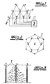
- 1 is a borehole pattern with individual boreholes 1 shown. In these holes 1 are Explosive charges with associated detonators 2 used all connected to a central control unit 3 are.
- igniters 2 are within the scope of the exemplary embodiment around electronic detonators 2 which are as in 5 are constructed in detail. So points each electronic detonator 2 an energy storage 4 in Form one or more capacitors. This Energy store 4 is followed by an electronic switch 5, at which it is within the scope of the embodiment Switching transistor is. This switching transistor 5 is with the help of a data control part or a computer unit 6 or a microchip controlled. Once this microchip or computer 6, the electronic switch 5 in the transferred conductive state, is from the energy storage 4 supplied electrical energy on associated ignition cables 7 are available, which are the most detailed Ignite explosive charge, not shown. Of course are still not essential to the invention Components of the electronic detonator 2 such as power supply and / or rectifier realized as in Detail is described in DE-OS 197 21 839.
- the central ensures Control unit 3 for the corresponding adjustment of individual detonators 2 with each other. Basically, can such a central control unit 3, of course be dispensed with, so that the individual igniters 2 at Introduction into the respective borehole 1 can be programmed (have to).
- control unit 3 enables a central one Programming the shot pattern to be set and of course also changing it, if desired should.
- the detonators 2 are corresponding to that freely programmable method already described, whereby a mineralogical and / or geological environment appropriate shot pattern, d. H. a certain firing order or a selectable firing pattern can be.
- the lowercase letters a, b, c, d and e designate boreholes 1, the first Drill hole - a - is fired first and then the drill holes follow 1 with the designation b etc.
- the lower case letters represent the firing order or firing pattern. you recognizes that three (or more) rows of boreholes with each other are networked and a cross-row ignition pattern form.
- the explosion at borehole 1 with the Marking a started as a single shot.
- This Single shot a can be made according to the borehole depth so delayed to the subsequent shots that a Movement of the masses in the first shot area possible becomes.
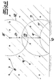
- FIG. 2 illustrates several opening circles that can be arranged around a symmetrical center with the designation a.
- Opposing boreholes 1 (b, c, d) are ignited in pairs, at the same time. This allows a fully effective opening of the borehole 1, which is blown up first (designation a). This is particularly evident in the section according to FIG. 3. 4 visualizes the horizontal ignition speed v ZH set according to the invention, which in the described manner is always greater than or equal to the (previously determined) rock speed v G.
- the pre-split holes 8 ignited together or in groups. This also applies to the production wells 9. This is through related Shock wave fronts 11, 12 shown. Corresponds the shock wave front 11 to a first ignited Production well 9 '. This includes one reflected shock wave front 11 '.
- the core procedure is such that a distance D between the production borehole 9 'and the associated gap borehole 8' influences the time delay ⁇ T of the associated ignition times, taking into account the rock speeds v G as follows: ⁇ T ⁇ D / v G
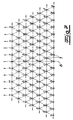
- FIG. 7 is a compared to FIG. 1st supplemented borehole pattern shown.
- the explosion marked with b follows Drill holes 1, in this case at an interval of approx. 40 to 60 msec. Of course, this depends in particular on Distance between the holes 1 to each other and the to be resolved Rock morphology.
- Blast b is followed by Holes marked c, in one time interval of approx. 3 to 10 msec compared to the boreholes b.
- the temporal ones are similar Distances to the subsequent explosions d, e, f, etc. sized.
- the last borehole 1 shown and to be blasted with the designation 1 is ignited about 90 to 100 msec after the borehole 1 with the designation a.
- the distance between the first ignited borehole 1 marked a to the last triggered borehole 1 labeled 1 is approximately 200 m.
- a horizontal ignition speed v ZH of approx. 2000 m / s is calculated from this.
- This horizontal ignition speed v ZH is significantly larger than the rock speed v G , which in the example shown does not even reach 1000 m / s. Ie the relation already explained applies: v ZH ⁇ v G ,
- the well pattern shown in Fig. 7 is designed mirror-symmetrical to an axis of symmetry S. in the Incidentally, it turns out that subsequent ignitions are distributed over at least two adjacent ignition rows, so that the already mentioned cross-row Ignition pattern results.
- the holes 1 in Broadly ignited from row to row. This means that starting with the first row continuous shock waves into the blasting area.
- Drill holes 1 again dimensioned so that when they arrive the shock wave at neighboring borehole 1 already detonated.
- This gas pressure wave arises after the implementation of the Explosives and will use one versus seismic Wave generated slower reproductive rate. Most often, this rate of reproduction is in the subsonic area while the shock wave velocity in the supersonic range (supersonic range) is located.
Landscapes
- Engineering & Computer Science (AREA)
- Life Sciences & Earth Sciences (AREA)
- Remote Sensing (AREA)
- Physics & Mathematics (AREA)
- Environmental & Geological Engineering (AREA)
- Acoustics & Sound (AREA)
- General Engineering & Computer Science (AREA)
- Geology (AREA)
- General Life Sciences & Earth Sciences (AREA)
- General Physics & Mathematics (AREA)
- Geophysics (AREA)
- Drilling And Exploitation, And Mining Machines And Methods (AREA)
- Geophysics And Detection Of Objects (AREA)
Description
Die Erfindung betrifft ein Verfahren zum Sprengen von Gesteinsmassen oder dergleichen Massen Übertage oder Untertage, wonach in Bohrlöcher Sprengladungen mit jeweils zugehörigem Zünder eingesetzt werden, und wonach die Zünder und deren jeweilige Verzögerungsintervalle zueinander in Abhängigkeit von dem mineralogischen/geologischen Umfeld und den daraus resultierenden seismischen Geschwindigkeiten sowie unter Berücksichtigung des jeweiligen Schussbildes programmiert werden.The invention relates to a method for blasting Rock masses or similar masses above ground or Underground, after which explosive charges in each borehole associated igniter are used, and then the igniter and their respective delay intervals to each other in Dependence on the mineralogical / geological environment and the resulting seismic speeds as well as taking into account the respective shot pattern be programmed.
Ein solches Sprengverfahren wird in der US 5 388 521 beschrieben. Hier geht es darum, Vibrationen an bestimmten Orten auf ein Minimum zu reduzieren und auf diese Weise die für eine Fragmentierung zur Verfügung stehende Energie zu erhöhen.Such a blasting process is described in US 5,388,521 described. This is about vibrating on certain Places to a minimum and in this way the available energy for fragmentation increase.
Ferner sind Sprengverfahren ohne Einstellung der jeweiligen Verzögerungsintervalle aus der Praxis bzw. der europäischen Patentanmeldung 0 147 688 A2 sowie der deutschen Offenlegungsschrift DE 197 21 839 A1 bekannt.Furthermore, blasting procedures are without adjustment of the respective Delay intervals from practice or European Patent application 0 147 688 A2 and the German published application DE 197 21 839 A1 known.
Bei solchen Sprengverfahren hat sich herausgestellt, dass der Zünder bzw. das eingesetzte Zündmittel wesentlich die Qualität des Sprengergebnisses beeinflusst. Hier unterscheidet man grundsätzlich zwischen elektrischen, nicht elektrischen und elektronischen Zündern. With such blasting procedures it has been found that the igniter or the ignition means used essentially the Quality of the blast result influenced. Differentiates here one basically between electrical, not electrical and electronic detonators.
Bei elektrischen Zündern wird regelmäßig auf einen pyrotechnischen Zündsatz in Verbindung mit einer Glühbrücke zurückgegriffen, welche durch elektrische Energie erhitzt wird. Ein nicht elektrischer Zünder besteht zumeist aus einem dünnen Plastikschlauch, in welchem ein Sprengstoff enthalten ist. Dieser Schlauch wird durch einen Schlag gezündet bzw. durch eine Sprengkapsel seinerseits initiiert. Der Plastikschlauch zündet dann einen ebenfalls pyrotechnischen Verzögerungssatz im eigentlichen Zünder.In the case of electrical detonators, a pyrotechnic is regularly used Ignition charge in connection with a glow plug resorted to, which is heated by electrical energy becomes. A non-electrical detonator usually consists of a thin plastic tube in which an explosive is included. This hose will blow detonated or in turn by a detonator initiated. The plastic hose will also ignite you pyrotechnic delay set in the actual igniter.
Elektronische Zünder kommen ohne einen pyrotechnischen Zündsatz aus. Denn sie erhalten ihre Energie regelmäßig über einen Energiespeicher, beispielsweise einen Kondensator. Dieser Kondensator dient zum Zünden einer Glühbrücke oder einer anderen elektrisch aufheizbaren Vorrichtung, wie dies grundsätzlich in der eingangs bereits angeführten europäischen Schrift oder der deutschen Offenlegungsschrift DE 197 21 839 A1 beschrieben ist.Electronic detonators come without a pyrotechnic one Ignition charge off. Because they get their energy regularly via an energy store, for example a capacitor. This capacitor is used to ignite a glow plug or another electrically heatable device, such as this is basically in the already mentioned European script or German published patent DE 197 21 839 A1 is described.
Ein ähnliches Verfahren ist Gegenstand der US 4 725 991, bei welchem es ebenfalls darum geht, Vibrationen und die Geräuschentwicklung auf ein Minimum zu reduzieren.A similar process is the subject of US 4,725,991, which is also about vibrations and the Reduce noise to a minimum.
Schließlich kennt man Details von in Bohrlöcher eingesetzten Sprengladungen durch die GB 961 324.After all, you know details of those used in boreholes Explosive charges by GB 961 324.
Die bisher bekannten Sprengverfahren können nicht in allen Punkten überzeugen. Denn bislang kommt es allenfalls zu einer gegenseitigen Unterstützung benachbarter Bohrlöcher innerhalb einer Bohrlochreihe im Sinne einer Intensivierung der Auflösung der zu sprengenden Gesteinsmassen. Mit anderen Worten lässt sich die Energie eines Folgeschusses an einen vorhergehenden Schuss nicht oder nur unvollkommen ankoppeln. Im Übrigen sind derartige Phänomene bisher mehr oder minder zufällig und praktisch kaum vorhersehbar beobachtet worden. - Hier will die Erfindung insgesamt Abhilfe schaffen.The previously known blasting methods cannot be used in all Convince points. Because so far it has happened at best mutual support for adjacent boreholes within a row of boreholes in the sense of intensification the dissolution of the rock mass to be blasted. With in other words, the energy of a subsequent shot to a previous shot not or only imperfectly Docking. Incidentally, such phenomena have so far been more or less random and practically unpredictable been observed. - Here the invention as a whole Remedy.
Der Erfindung liegt das technische Problem zugrunde, ein derartiges Verfahren so weiter zu bilden, dass nicht nur eine gezielte gegenseitige Beeinflussung der von den einzelnen Bohrlöchern ausgehenden Schockwellen ermöglicht wird, sondern zusätzlich noch die Sprengwirkung im Bohrloch beeinflussbar ist.The invention is based on the technical problem to further develop such a process that not only a targeted mutual influence of those of the individual shock holes outgoing shock waves but also the explosive effect in the borehole can be influenced.
Zur Lösung dieser Aufgabe schlägt die Erfindung bei einem gattungsgemäßen Verfahren zum Sprengen von Gesteinsmassen oder dergleichen Massen vor, dass jeweils in ein Bohrloch ein elektronischer Bodenzünder und ein elektronischer Kopfzünder eingesetzt sind und auf den gleichen oder einen abweichenden Zündzeitpunkt programmiert werden, und dass dadurch gegenläufige Detonationsfronten in etwa in der Mitte der Ladungssäule unter Verdopplung der Detonationsgeschwindigkeit und beschleunigten Umsetzung der Ladesäule aufeinandertreffen.To achieve this object, the invention proposes Generic method for blasting rock masses or similar masses before that each in a borehole an electronic ground igniter and an electronic one Head detonators are used and on the same or one deviating ignition timing can be programmed, and that therefore opposite detonation fronts in about Middle of the charge column while doubling the Detonation speed and accelerated implementation of the The charging station meet.
Vorzugsweise korrespondieren die eingestellten Zündverzögerungen zwischen erstem und letztem Bohrloch zu einer Zündgeschwindigkeit (horizontale Zündgeschwindigkeit) welche gleich oder größer als die Schallgeschwindigkeit im zu sprengenden Gestein (Gesteinsgeschwindigkeit) ist.The set ignition delays preferably correspond between the first and last borehole to one Ignition rate (horizontal ignition rate) which are equal to or greater than the speed of sound in the to be blasted rock (rock speed).
Dabei kommen zumeist elektronische Zünder mit einem stufenlos und exakt einstellbaren Zündzeitpunkt zum Einsatz. Denn mit Hilfe derartiger elektronischer Zünder lassen sich zum ersten Mal frei programmierbare und variierende Zündintervalle von Zünder zu Zünder bzw. von Bohrloch zu Bohrloch einstellen. Dies lässt sich im Kern darauf zurückführen, dass bei elektronischen Zündern - wie bereits beschrieben wurde - auf einen pyrotechnischen Zündsatz bewusst verzichtet wird.Mostly electronic detonators come with one infinitely and precisely adjustable ignition timing at Commitment. Because with the help of such electronic detonators are freely programmable for the first time varying ignition intervals from igniter to igniter or from Adjust borehole to borehole. In essence, this can be attributed to the fact that with electronic detonators - like has already been described - on a pyrotechnic Ignition charge is deliberately dispensed with.
Vielmehr sorgt hier ein dem Energiespeicher bzw. Kondensator nachgeschalteter elektronischer Schalter (zumeist in Form eines Schalttransistors) dafür, dass in dessen leitendem Zustand der Energiespeicher auf das an eine Zündleitung angeschlossene Zündmittel entladen wird. Dabei kann der elektronische Schalter bzw. Schalttransistor mit Hilfe eines Datensteuerteils inklusive zentraler Steuereinheit, also eines Rechners in Form eines Mikrochips, entsprechend gesteuert werden. Auf diese Weise kann der jeweils eingesetzte elektronische Zünder zeitgenau ausgelöst werden, wobei Genauigkeiten unterhalb von einer Millisekunde erreichbar sind.Rather, the energy storage or Downstream capacitor electronic switch (usually in the form of a switching transistor) for the fact that in the conductive state of the energy storage on the an ignition cable connected to the ignition device is discharged. The electronic switch or switching transistor with the help of a data control part including a central one Control unit, i.e. a computer in the form of a Microchips, controlled accordingly. In this way the electronic detonator used can be timely are triggered, with accuracies below one Milliseconds can be reached.
Darüber hinaus schlägt die Erfindung zur Erhöhung der Sprengwirkung vor, dass einzelne, von den jeweiligen Bohrlöchern ausgehende Schockwellenfronten zur Öffnung des Gefüges des zu sprengenden Gesteins miteinander interferieren. Es kommt also zu einer Interferenz der Schockwellen und folglich auch der erzeugten seismischen Wellen. Dieses Auf- und Ineinandertreffen der verschiedenen multiplen Wellenfronten führt zur gewünschten Öffnung des Gefüges, also dazu, dass sich die Bindungen in den jeweiligen Festkörpern infolge der äußeren Erregung (zumindest teilweise) lösen. In addition, the invention proposes to increase the Explosive effect before that individual, from the respective Shock wave fronts emanating from holes to open the Structure of the rock to be blasted together interfere. So there is an interference of the Shock waves and consequently the generated seismic Waves. This clash of the different multiple wave fronts leads to the desired opening of the Structure, that is to say that the bonds in the respective solids due to external excitation solve (at least partially).
Unter Schockwellen werden nach üblichem Verständnis sich räumlich ausbreitende abrupte, aber stetige Veränderungen von Dichte, Druck und/oder Temperatur des jeweils zu sprengenden Materials verstanden. Eine derartige Schockwelle entsteht, wenn plötzlich ein großer Energiebetrag freigesetzt wird - nämlich durch die beschriebene Explosion bzw. das Zünden der Sprengladung im zugehörigen Bohrloch mit Hilfe des (elektronischen) Zünders. Die Vorderfront dieser Energieausbreitung stellt eine Schockwelle dar. Deren Ausbreitungsgeschwindigkeit bzw. die Schockwellengeschwindigkeit kann ein Vielfaches der Schallgeschwindigkeit des zugehörigen Mediums betragen und bewegt sich vorliegend im Überschallbereich.According to common understanding, shock waves become themselves spatially spreading abrupt but constant changes of density, pressure and / or temperature of each understood explosive material. Such a shock wave arises when suddenly a large amount of energy is released - namely by the described explosion or detonating the explosive charge in the associated borehole with the help of the (electronic) detonator. The front this energy spread represents a shock wave. Their propagation speed or the shock wave speed can be a multiple of the speed of sound of the associated medium and moves in the supersonic area.
Unter seismischen Wellen sind im Rahmen der vorliegenden Erfindung nicht nur Schockwellen bzw. Stoßwellen, sondern jegliche (Erschütterungs-)Wellen zu verstehen, die sich von einem Erregerzentrum (zumeist dem Bohrloch mit darin befindlicher Sprengladung) im zu sprengenden Gestein fortpflanzen.Under seismic waves are within the scope of the present Invention not only shock waves or shock waves, but to understand any (shock) waves that arise from an excitation center (mostly the borehole with it explosive charge) in the rock to be blasted.
Da die Ausbreitungsgeschwindigkeit der jeweiligen seismischen Welle - abgesehen von sogenannten Stoßwellen bzw. Schockwellen - vom zugehörigen Material bzw. dessen Kompressibilität (insbes. dem Elastizitätsmodul) abhängt, stellt sich bei bekannter Dichte und vorgegebener Temperatur eine ganz bestimmte und charakteristische Fortpflanzungsgeschwindigkeit ein, die Schallgeschwindigkeit. Diese repräsentiert also praktisch einen materialabhängigen Parameter und kann bei Gesteinen durchaus über 1000 m/s oder sogar mehrere 1000 m/s betragen. Because the speed of propagation of each seismic wave - apart from so-called shock waves or shock waves - from the associated material or its Compressibility (especially the modulus of elasticity) depends, arises at a known density and more predetermined Temperature a very specific and characteristic reproductive rate a, the speed of sound. This practically represents a material-dependent one Parameters and can be over 1000 m / s for rocks or even several 1000 m / s.
Der Bereich elastischer Deformationen und vorgegebener Kompressibilitäten des die seismische Welle bzw. Schallwelle leitenden Gesteins wird dann verlassen, wenn nicht mehr nur Wellen kleiner Amplitude im Gestein angeregt werden. Denn bei großen, gleichsam schlagartigen Anregungen kommt es zur Ausbildung der bereits angesprochenen Schock- bzw. Stoßwellen. Diese sorgen zumindest im Sprengbereich vorteilhaft dafür, dass die Atome im Festkörpergitter keine elastische Verformung (mehr) gegeneinander erfahren, also die Bindungen aufbrechen. Das Festkörpergefüge wird (größtenteils) zerstört.The range of elastic deformations and predetermined Compressibilities of the seismic wave or sound wave guiding rock will be left if not more only waves of small amplitude are excited in the rock become. Because with large, as it were sudden suggestions it comes to the formation of the shock or shock waves. These provide at least in the blasting area advantageous that the atoms in the solid-state lattice are none experience elastic deformation (more) against each other, so break the bonds. The solid state structure becomes (mostly) destroyed.
Dadurch, dass die Schockwellengeschwindigkeit zumeist im Überschallbereich angesiedelt ist, stellen sich Machzahlen von 1 und größer für diese Geschwindigkeit ein. Dabei werden aufeinanderfolgende Sprengungen zur Erhöhung der Sprengwirkung von Bohrloch zu Bohrloch unter Berücksichtigung der jeweiligen Zündfolge aneinander angekoppelt, d. h. die sich von den zugehörigen Bohrlöchern ausbreitenden Schockwellen (und auch die übrigen seismischen Wellen, insbesondere Schallwellen) überlagern sich und interferieren. Es kommt zu einer Verdichtung des Schockwellensystems im Sprengbereich. Mit anderen Worten werden Wellenamplituden erzeugt, die aus der (positiven) Überlagerung einzelner Schockwellen resultieren. Dies kann durch die programmierten Zündverzögerungen eingestellt werden, so dass insgesamt ein Schockwellensystem entsteht, dessen jeweils addierte Wellengeschwindigkeiten sich im Überschallbereich ausbreiten, d.h. Geschwindigkeiten aufweisen, die oberhalb von Mach 1 liegen. Because the shock wave velocity mostly in Mach numbers are located in the supersonic area of 1 and greater for this speed. there are successive explosions to increase the Explosion effect from borehole to borehole under consideration the respective firing order coupled to each other, d. H. which is different from the associated drill holes propagating shock waves (and the rest seismic waves, especially sound waves) themselves and interfere. There is a compression of the Shock wave system in the blasting area. In other words wave amplitudes are generated, which result from the (positive) Superposition of individual shock waves result. This can set by the programmed ignition delays so that a shock wave system is created overall, whose respectively added wave speeds are in Spread out the supersonic area, i.e. speeds that are above Mach 1.
Die eingestellten Zündverzögerungen korrespondieren zu einer kumulierten Summe, die kleiner ist als die aus der Schallgeschwindigkeit im zu sprengenden Gestein resultierenden Laufzeit. D. h., die horizontale Zündgeschwindigkeit ist gleich oder größer als die Schallgeschwindigkeit im zu sprengenden Gestein.The set ignition delays correspond to a cumulative sum less than that from the Speed of sound resulting in the rock to be blasted Running time. That is, the horizontal ignition speed is equal to or greater than the speed of sound in the rock to be blasted.
Hierdurch lassen sich bestimmte Verzögerungsmuster der einzelnen Zündfolgen, also sog. Schussbilder, erstellen. Dabei bestimmt die Auswahl der jeweiligen Verzögerungen die Zerkleinerung des gesprengten Materials (das sog. Haufwerk) und sogar dessen Verteilung bzw. Anhäufung im Bereich der Sprengstelle bzw. im Sprengbereich. Wenn nämlich einzelne seismische Wellen so interferieren, dass an bestimmten, räumlich exakt einzugrenzenden Stellen, Interferenzberge entstehen, so ist hier mit einer besonders intensiven Öffnung der zu sprengenden Gesteinsmassen zu rechnen. Dagegen korrespondieren Interferenztäler zumeist zu der Situation, dass hier keine oder nur eine begrenzte Öffnung der Gesteinsmassen erfolgt.This allows certain delay patterns create individual firing sequences, so-called shot patterns. The selection of the respective delays determines the Shredding of the blasted material (the so-called pile) and even its distribution or accumulation in the area of Blast site or in the blasting area. If only individual seismic waves interfere so that at certain locations to be delimited exactly, mountains of interference arise, so here is with a particularly intense Opening of the rock masses to be blasted. In contrast, interference valleys mostly correspond to that Situation that here no or only a limited opening of the rock masses.
Da sich die seismischen Wellen vorliegend jedoch vom jeweiligen Bohrloch ausgehend (zumindest) mit der Schallgeschwindigkeit im jeweiligen Gestein ausbreiten, kommt es zu laufenden Wellenmustern und demzufolge auch zu wandernden Interferenzbergen und -tälern. Dabei sind sowohl gegenläufige als auch mitlaufende seismische Wellen bzw. Schallwellen und/oder Schockwellen denkbar.However, since the seismic waves differ from respective borehole starting (at least) with the Spread the speed of sound in the respective rock, there are running wave patterns and consequently also wandering interference mountains and valleys. Both are opposing as well as moving seismic waves or Sound waves and / or shock waves possible.
Jedenfalls führt dies insgesamt dazu, dass durch die beschriebenen Wellenkollisionen Verdichtungseffekte durch das multiple Hin- und Her- bzw. Durchlaufen der jeweiligen Wellenfronten durch die Gesteinsmassen beobachtet werden. Es kommt also durch die mit bestimmter Zündfolge nacheinander explodierenden Sprengladungen in den zugehörigen Bohrlöchern zu einem quasi - kontinuierlichen Prozess der Erzeugung einer seismischen Interferenz- bzw. Schockwelle mit Strömungscharakter. Dies führt dazu, dass zumindest im sog. Nahfeldbereich (Sprengbereich) die zu sprengenden Gesteinsmassen in ein Mineralgemenge mit kolloidal-mechanischem Zusammenhalt überführt werden.In any case, this leads overall to the fact that described wave collisions by compression effects the multiple back and forth or going through each Wave fronts can be observed through the rock masses. So it comes through with a certain firing order sequentially exploding charges in the associated drill holes to a quasi - continuous Process of generating a seismic interference or Shock wave with a flow character. This leads to at least in the so-called near field area (blasting area) blasting rock masses into a mineral mix colloidal-mechanical cohesion.
Dieser Nahfeldbereich ist dadurch gekennzeichnet, dass die durch die Sprengung erzeugte Schockwelle bzw. seismische Welle hier besonders hochfrequent ist. Diese hochfrequente Schockwelle nähert sich entfernungsabhängig der Schallgeschwindigkeit im zu sprengenden Gestein und auch der zugehörigen Eigenfrequenz.This near field area is characterized in that the shock wave or seismic generated by the explosion Wave is particularly high frequency here. This high frequency Shock wave approaches the speed of sound depending on the distance in the rock to be blasted and also the associated natural frequency.
Die beschriebene Schockwirkung lässt sich auf eine gleichsam impulsartige Anregung der Gesteinsmassen infolge der Detonation der Sprengladung im zugehörigen Bohrloch zurückführen, welche im Frequenzraum zu den hier beobachteten ultrahohen Frequenzen im Bereich von 400 Hz bis zu mehreren kHz korrespondiert.The shock effect described can be reduced to one as it were impulse-like excitation of the rock masses as a result the detonation of the explosive charge in the associated borehole return which in the frequency domain to the here observed ultra high frequencies in the range of 400 Hz corresponds to several kHz.
Jedenfalls sind Frequenz und Amplitude dieser Schockwellen im Nahfeldbereich bzw. Nahbereich (Sprengbereich) geeignet, das Festkörpergefüge der Gesteinsmassen so stark anzuregen, dass dies eine teilweise oder gänzliche Auflösung des Festkörpers zur Folge hat. Folglich legt der Nahfeldbereich bzw. Nahbereich den eigentlichen Sprengbereich fest, innerhalb dessen sich die seismische Welle bzw. Schockwelle konzentrisch vom Mittelpunkt der Erregerquelle, also der Sprengladung bzw. dem Bohrloch, ausbreitet.In any case, the frequency and amplitude of these shock waves suitable in the near field or close range (blasting area), to stimulate the solid structure of the rock masses so strongly that this is a partial or total dissolution of the Solid body results. Consequently, the near-field area or the immediate area the actual blasting area, within which there is the seismic wave or shock wave concentric from the center of the excitation source, i.e. the Explosive charge or the borehole.
Wie bereits ausgeführt, hängen die frei programmierbaren Zündverzögerungen und die sich hieraus ergebende Zündgeschwindigkeit entscheidend von der Schallgeschwindigkeit im jeweils aufzusprengenden Gestein ab. Mit anderen Worten muss die Zündgeschwindigkeit an die sich einstellenden physikalischen Geschwindigkeiten (insbesondere Schallgeschwindigkeit) angepasst werden.As already stated, the freely programmable hang Ignition delays and the resulting ignition speed crucial from the speed of sound in the rock to be blasted off. In other words the ignition speed must match the physical speeds (especially speed of sound) be adjusted.
Um dies zu erreichen, schlägt die Erfindung vor, dass die seismische Geschwindigkeit bzw. Schallgeschwindigkeit im zu sprengenden Gestein zuvor, d. h. vor der Programmierung der Zünder und natürlich vor der Sprengung, messtechnisch und/oder rechnerisch durch Simulationen ermittelt wird. Zu diesem Zweck lassen sich beispielsweise Bohrprotokolle heranziehen, die ein ziemlich genaues Abbild der jeweiligen Gesteinsformationen liefern. Aus diesen Bohrprotokollen kann auf die zu erwartenden seismischen Geschwindigkeiten zurückgeschlossen werden, so dass sich anhand dieser Erkenntnisse die horizontale Zündgeschwindigkeit, also die Geschwindigkeit der Zündung vom ersten Bohrloch bis zum letzten Bohrloch, bemisst bzw. einstellen lässt.To achieve this, the invention proposes that the seismic speed or speed of sound in the previously exploding rock, d. H. before programming the Detonator and, of course, before the explosion, metrologically and / or is determined mathematically by simulations. To For this purpose, drilling logs can be used, for example use a fairly accurate replica of each Deliver rock formations. From these drilling logs can depend on the expected seismic speeds be inferred so that based on this Findings of the horizontal ignition speed, i.e. the Ignition speed from the first borehole to last borehole, dimensioned or adjusted.
Dabei ist es grundsätzlich auch denkbar, unter Rückgriff auf jeweils am Außenrand des gewünschten Sprengbereiches angeordnete Bohrlöcher gegenläufige Schockwellen bzw. seismische Wellen zu erzeugen. Hierdurch kann das Sprengfeld in einer Weise begrenzt werden, die bisher im Stand der Technik nicht für möglich gehalten wurde. Hierfür sorgt immer das gleichsam frei programmierbare Schussbild mit den jeweils eingestellten Verzögerungen von Sprengung zu Sprengung.In principle, it is also conceivable to use recourse on the outer edge of the desired blasting area arranged drill holes opposing shock waves or to generate seismic waves. This can Explosive field can be limited in a way that was previously in the State of the art was not considered possible. Therefor always ensures the freely programmable shot pattern with the set delays of blowing up to blowing up.
Neben der erzeugten seismischen Welle bzw. Schallwelle (Schockwelle) dient zusätzlich noch zur Zerkleinerung des gesprengten Gesteins eine zeitlich nach Umsetzung des Sprengstoffes folgende Gasdruckwelle. Diese wird mit gegenüber der seismischen Welle geringerer Fortpflanzungsgeschwindigkeit, der sog. Detonationsdruckwellengeschwindigkeit, erzeugt. Jedenfalls unterstützt die Gasdruckwelle die Sprengwirkung der Schockwelle. Denn diese Gasdruckwelle dringt in bereits bestehende Haarrisse ein, so dass die zugehörigen Gesteinsbrocken hierdurch geöffnet werden. Auch ist es denkbar, dass die Gasdruckwelle selbst Gestein oder bestimmte Gesteinsbrocken zerkleinert.In addition to the generated seismic wave or sound wave (Shock wave) is also used to shred the blasted rock a time after implementation of the Explosives following gas pressure wave. This is with compared to the seismic wave slower propagation speed, the so-called detonation pressure wave velocity, generated. Anyway supports the Gas blast the explosive effect of the shock wave. Because this Gas pressure wave penetrates into existing hairline cracks, so that the associated chunks of rock are opened become. It is also conceivable that the gas pressure wave itself Crushed rock or certain chunks of rock.
In diesem Zusammenhang sieht die Erfindung ferner vor, dass die Schockwellengeschwindigkeit bzw. seismische Geschwindigkeit und die Detonationsdruckwellengeschwindigkeit aufeinander abgestimmt und im Überschall- respektive Unterschallgeschwindigkeitsbereich angesiedelt sind.In this context, the invention further provides that the shock wave velocity or seismic velocity and the blast wave velocity coordinated and in supersonic resp Subsonic speed range are located.
Diese Abstimmung der Schockwellengeschwindigkeit und der Detonationsdruckwellengeschwindigkeit aufeinander lässt sich darauf zurückführen, dass die Detonationsdruckwellengeschwindigkeit natürlich von dem Charakter und dem mechanischen Zusammenhalt der aufgesprengten Gesteinsmassen abhängt. Tendenziell ist mit einer umso größeren Detonationsdruckwellengeschwindigkeit zu rechnen, je geringer die Korngröße der jeweils aufgesprengten Gesteinsmasse nach der Sprengung bemessen ist. Diese wiederum ist Folge der Interferenzen der Schockwellen. This coordination of the shock wave speed and the Detonation pressure wave velocity leaves on each other attributed to the detonation pressure wave velocity of course of the character and that mechanical cohesion of the blasted rock masses depends. It tends to be the bigger Detonation pressure wave velocity to be expected, each smaller the grain size of each blown up Rock mass is measured after the explosion. This in turn is a result of the interference of the shock waves.
Im Rahmen der Erfindung lassen sich auch sogenannte Vorspaltsprengungen und Produktionssprengungen nicht nur voneinander unterscheiden, sondern auch synchronisieren. Unter Vorspaltreihen sind im Rahmen der Erfindung bestimmte Bohrlochtopologien im Rahmen des erzeugten Bohrlochmusters zu verstehen. Derartige Vorspaltreihen finden sich zumeist als Begrenzung des eigentlichen Sprengbereiches und sollen u. a. für eine möglichst gerade und stabile Abbauwand nach Beendigung der Sprengung sorgen. Dementsprechend ist es denkbar, dass Vorspaltbohrlöcher den Sprengbereich insgesamt umschließen oder zumindest an einer Seite begrenzen, wo die beschriebene gerade und stabile Abbauwand gewünscht wird. Die Sprengung der zugehörigen Sprengladungen in den die Vorspaltreihen bildenden Bohrlöchern wird dabei als Vorspaltsprengung bezeichnet. Im Gegensatz dazu dienen Produktionssprengungen dem eigentlichen Zweck, die Gesteinsmassen innerhalb des Sprengfeldes bzw. Sprengbereiches aufzulösen.So-called Pre-garbage blasting and production blasting not only distinguish from each other, but also synchronize. Under gap rows are within the scope of the invention certain well topologies in the context of the generated borehole pattern to understand. Find such pre-gap rows mostly as a limitation of the actual Blasting area and should u. a. for one as straight as possible and stable dismantling wall after the explosion has ended. Accordingly, it is conceivable that pre-gap boreholes Enclose the blasting area as a whole or at least on one Limit side where described straight and stable Dismantling wall is desired. Blowing up the associated Explosive charges in the holes forming the pre-gap rows is referred to as pre-garbage. in the In contrast, production explosions serve the real thing Purpose, the rock masses within the blasting field or to explode the explosive area.
Durch die präzise und programmierbare Einstellung der jeweils verwendeten elektronischen Zünder ist es möglich, die Vorspaltsprengung und die eigentliche Produktionssprengung aufeinander abzustimmen. Dabei wird zumeist so vorgegangen, dass nach Zünden der Produktionssprengung in unmittelbarem zeitlichen Abstand eine zugehörige Vorspaltsprengung durchgeführt wird. Hierdurch wird erreicht, dass die von den zugehörigen Produktionsbohrlöchern jeweils ausgehenden seismischen Wellen mit den kurz danach ausgesandten seismischen Wellen der Vorspaltbohrlöcher interferieren. The precise and programmable setting of the used electronic detonators it is possible the pre-gap blasting and the actual production blasting to coordinate with each other. It is usually like this proceeded that after detonating the production explosion in an associated pre-gap detonation immediately afterwards is carried out. This ensures that from the associated production wells, respectively outgoing seismic waves with those emitted shortly thereafter seismic waves of the pre-gap boreholes interfere.
In diesem Zusammenhang wird die Auslegung so getroffen, dass die jeweiligen Ausbreitungsrichtungen mehr oder minder entgegengesetzt verlaufen, so dass es zu Wellenkollisionen innerhalb des Sprengfeldes kommt. Dieser Effekt wird noch durch die üblicherweise an der zu definierenden Abbauwand bzw. sogenannten freien Fläche reflektierten seismischen Wellen der zuerst gezündeten Produktionsbohrlöcher verstärkt.In this context, the interpretation is made so that the respective directions of propagation more or less run in the opposite direction, causing wave collisions comes within the blasting field. This effect will still be there through the usually on the wall to be defined or so-called free area reflected seismic Shafts of the first fired production wells reinforced.
Jedenfalls erfolgt eine Synchronisation zwischen Vorspaltsprengung und Produktionssprengung dergestalt, dass Erschütterungen im Sprengbereich (und auch außerhalb des Sprengbereiches) neutralisiert werden. Im Idealfall wird also der Sprengbereich (und der ihn umgebende Außenbereich) bzw. die gewünschte Abbauwand nur unwesentlich erschüttert.In any case, a synchronization between pre-gap blasting takes place and demolition of production in such a way that Vibrations in the blasting area (and also outside the Explosive area) are neutralized. Ideally it will ie the blasting area (and the surrounding area) or the desired dismantling wall only slightly shaken.
Dabei liegt es selbstverständlich im Rahmen der Erfindung, einzelne Bohrlochsprengungen zeitlich zu einer gemeinsam gezündeten Bohrlochreihe bzw. Vorspaltbohrlochreihe zusammenzufassen. In gleicher Weise können einzelne Produktionsbohrlöcher ein Konglomerat bilden, welches gemeinsam gezündet wird. Dies gilt natürlich grundsätzlich für sämtliche Bohrlöcher im Rahmen der Erfindung, d. h. ungeachtet der vorgenannten Unterscheidung zwischen Vorspaltbohrlöchern und Produktionsbohrlöchern. Denn Bohrlochmuster, Zündfolgen bzw. Schussbilder und jeweilige Verzögerungen der Zündungen untereinander können bekanntlich frei wählbar programmiert werden.It is of course within the scope of the invention individual borehole blasts together in time ignited row of boreholes or pre-tunnels summarize. In the same way, individual Production wells form a conglomerate which is ignited together. Of course, this basically applies for all boreholes within the scope of the invention, d. H. regardless of the above distinction between pre-gap wells and production wells. Because borehole patterns, Firing sequences or shot patterns and respective As is well known, delays between the ignitions can occur freely programmable.
Insgesamt ermöglicht die beschriebene Vorspalttechnik
insbesondere in sensiblen und sogar bewohnten Gebieten eine
zuvor festgelegte und definierte Begrenzung des Sprengbereiches.
Dabei bildet die Vorspaltreihe praktisch einen
Reflektionshorizont für die eigentliche Produktionssprengung.
- Gegenstand der Erfindung ist auch ein
Bohrlochmuster, wie es in den Patentansprüchen 9 und 10
beschrieben wird.Overall, the pre-splitting technique described enables
especially in sensitive and even inhabited areas
previously defined and defined limitation of the blasting area.
The pre-gap row practically forms one
Reflection horizon for the actual production explosion.
- The subject of the invention is also a
Borehole patterns as set out in
Immer erlauben die regelmäßig eingesetzten elektronischen Zünder eine praktisch totale Kontrolle über den jeweils programmierten Zündzeitpunkt. Hierdurch lässt sich nicht nur die Abbrandgeschwindigkeit der Sprengstoffe beherrschen, sondern diese kann auch zur Manipulation der Sprengwirkung im jeweiligen Bohrloch genutzt werden. Dies ist unter Berücksichtigung der kopf- und bodenseitigen Anordnung einer Sprengladung mit Bezug zum jeweiligen Bohrloch bereits beschrieben worden.The regularly used electronic allow Detonator practically total control over each programmed ignition timing. This cannot be done only master the rate of combustion of the explosives, but this can also be used to manipulate the Explosive effects can be used in the respective borehole. This is taking into account the top and bottom Arrangement of an explosive charge with reference to the respective Well has already been described.
Als weitere Vorteile des erfindungsgemäßen Verfahrens sind zu nennen, dass mit der Auslegung der Zündanlage bzw. durch die Kopplung der Zündungen untereinander und deren Programmierung eine praktisch neue Wirkungsebene erschlossen wird. Mit anderen Worten lässt sich eine Sprengung nun nicht mehr durch die Bohrlochgeometrie und den eingesetzten Sprengstoff allein beeinflussen, sondern zusätzlich noch durch die beschriebene Programmierung und die eingestellte Zündabfolge.Further advantages of the method according to the invention are to mention that with the design of the ignition system or by the coupling of the ignitions with each other and their Programming a practically new level of effectiveness is developed. In other words, one can No longer blasting through the borehole geometry and influence the explosives alone, but additionally through the described programming and the set firing order.
Dabei lassen sich aus Schwingungen außerhalb des Sprengfeldes, d. h. im sogenannten Fernfeldbereich, Erkenntnisse zur Schadenskontrolle gewinnen, wie dies grundsätzlich bekannt ist. Auch können hieraus wichtige Ergebnisse für nachfolgende Sprengungen gewonnen werden. Denn die sich im Fernfeld fortpflanzenden seismischen Wellen liefern natürlich hervorragende Eingangswerte (insbesondere die Schallgeschwindigkeit im zugehörigen Material) für hier eventuell anzustrengende nachfolgende Sprengungen. Tatsächlich können aus diesen seismisch gewonnenen Werten natürlich in der beschriebenen Art und Weise die einzustellenden Zündgeschwindigkeiten, insbesondere die sogenannte horizontale Zündgeschwindigkeit, abgeleitet werden. Dabei ist wie üblich entscheidend, dass das letzte zu zündende Bohrloch kurz vor dem Eintreffen der Schockwelle gezündet wird.Vibrations outside the Explosive field, d. H. in the so-called far field area, knowledge to gain damage control like this is basically known. This can also be important Results for subsequent explosions can be obtained. Because the seismic propagating in the far field Waves naturally provide excellent input values (especially the speed of sound in the associated Material) for subsequent ones that may need to be worked on here Blasting. Indeed, these can seismic obtained values of course in the described manner and Way, the ignition speeds to be set, in particular the so-called horizontal ignition speed, be derived. As usual, it is crucial that the last borehole to be ignited shortly before the arrival of the Shock wave is ignited.
Im Rahmen des beschriebenen Verfahrens lässt sich folglich der spezifische Sprengstoffverbrauch deutlich reduzieren, weil Interferenzen der erzeugten seismischen Wellen bzw. Schockwellen bewusst und gezielt ausgenutzt werden. Dies führt zudem zu einem verringerten Aufwand bei der Herstellung der jeweiligen Bohrlöcher. Außerdem eröffnet die Erfindung die Möglichkeit, zumindest im Randbereich gegenläufige Schockwellen erzeugen zu können, so dass ein eng eingegrenztes Sprengfeld definiert ist und profilübergreifende Auswirkungen infolge der Sprengung auf ein Minimum reduziert sind.As a result, within the scope of the described method significantly reduce specific explosives consumption, because interference of the generated seismic waves or Shock waves can be used consciously and in a targeted manner. This also leads to a reduced effort in the Production of the respective boreholes. Also opened the invention the possibility, at least in the marginal area to generate opposing shock waves, so that a narrowly defined explosive field is defined and cross-profile Effects of the explosion on a Minimum are reduced.
Gegenüber dem Stand der Technik und bei kurzen Bohrlochabständen lassen sich insbesondere sogenannte sympathetische Übertragungen von einem zum Nachbarloch vermeiden. Das heißt, es kommt ausdrücklich nicht zu einer Verdichtung einer Sprengladung im benachbarten Bohrloch durch die mittels des erstgezündeten Bohrloches erzeugte Schockwelle. Nichtdetonationen, wie sie früher beobachtet wurden, sind also ausgeschlossen. Denn bevor die seismische Welle bzw. Schockwelle das benachbarte Bohrloch erreicht hat, ist dessen Zündung bereits erfolgt.Compared to the state of the art and with short borehole distances so-called sympathetic Avoid transfers from one hole to the next. That is, there is expressly no one Compaction of an explosive charge in the neighboring borehole by the generated by the first ignited borehole Shockwave. Non-detonations, as observed earlier were excluded. Because before the seismic Wave or shock wave reaches the adjacent borehole has already ignited.
Dies hat darüber hinaus zur Konsequenz, dass der Sprengbetrieb insgesamt deutlich sicherer und einfacher wird. Dabei ist grundsätzlich auch die Einhaltung zusätzlicher Sicherheitsstandards denkbar, wie sie in der eingangs bereits zitierten deutschen Offenlegungsschrift 197 21 839 A1 dargelegt sind.This also means that the Blasting operations overall much safer and easier becomes. Basically, compliance is also included additional security standards as conceivable in the German Offenlegungsschrift already cited at the beginning 197 21 839 A1 are set out.
Im Folgenden wird die Erfindung anhand einer lediglich ein Ausführungsbeispiel darstellenden Zeichnung näher erläutert; es zeigen:
- Fig. 1
- ein Bohrlochmuster mit drei untereinander vernetzten Bohrlochreihen,
- Fig. 2
- ein anderes Bohrlochmuster,
- Fig. 3
- einen Schnitt durch Fig. 2,
- Fig. 4
- ein wiederum abgewandeltes Bohrlochmuster,
- Fig. 5
- einen Zünder in schematischer Darstellung,
- Fig. 6
- ein Bohrlochmuster bei einer Vorspaltsprengung und
- Fig. 7
- ein ergänztes Bohrlochmuster, von welchem die Fig. 1 einen Ausschnitt darstellt.
- Fig. 1
- a borehole pattern with three interconnected rows of boreholes,
- Fig. 2
- another hole pattern,
- Fig. 3
- 2 shows a section through FIG. 2,
- Fig. 4
- a again modified borehole pattern,
- Fig. 5
- a detonator in a schematic representation,
- Fig. 6
- a borehole pattern with a pre-split and
- Fig. 7
- an additional borehole pattern, of which Fig. 1 represents a section.
In der Fig. 1 ist ein Bohrlochmuster mit einzelnen Bohrlöchern
1 dargestellt. In diese Bohrlöcher 1 sind
Sprengladungen mit zugehörigen Zündern 2 eingesetzt, die
sämtlich an eine zentrale Steuerungseinheit 3 angeschlossen
sind.1 is a borehole pattern with
Bei diesen Zündern 2 handelt es sich im Rahmen des Ausführungsbeispiels
um elektronische Zünder 2, die wie in
Fig. 5 dargestellt im Einzelnen aufgebaut sind. So weist
jeder elektronische Zünder 2 einen Energiespeicher 4 in
Form eines oder mehrerer Kondensatoren auf. Diesem
Energiespeicher 4 folgt ein elektronischer Schalter 5, bei
dem es sich im Rahmen des Ausführungsbeispieles um einen
Schalttransistor handelt. Dieser Schalttransistor 5 wird
mit Hilfe eines Datensteuerteiles bzw. einer Rechnereinheit
6 oder eines Mikrochips gesteuert. Sobald dieser Mikrochip
bzw. Rechner 6 den elektronischen Schalter 5 in den
leitenden Zustand überführt, steht die vom Energiespeicher
4 gelieferte elektrische Energie an zugehörigen Zündleitungen
7 zur Verfügung, die unmittelbar die im Einzelnen
nicht dargestellte Sprengladung zünden. Selbstverständlich
sind noch weitere für die Erfindung nicht wesentliche
Bestandteile des elektronischen Zünders 2 wie Spannungsversorgung
und/oder Gleichrichter verwirklicht, wie dies im
Detail in der DE-OS 197 21 839 beschrieben ist.These
Jedenfalls wird deutlich, dass mit Hilfe des vom Mikroprozessor
6 gesteuerten elektronischen Schalters 5 das
Zünden der Sprengladung äußerst präzise eingestellt werden
kann, und zwar mit einer Genauigkeit, die im
Submillisekundenbereich liegt. Dabei sorgt die zentrale
Steuereinheit 3 für den entsprechenden Abgleich der
einzelnen Zünder 2 untereinander. Grundsätzlich kann auf
eine derartige zentrale Steuereinheit 3 natürlich auch
verzichtet werden, so dass dann die einzelnen Zünder 2 beim
Einbringen in das jeweilige Bohrloch 1 programmiert werden
(müssen).In any case, it becomes clear that with the help of the microprocessor
6 controlled electronic switch 5 that
Ignition of the explosive charge can be set extremely precisely
can, with an accuracy that in the
Sub-millisecond range. The central ensures
Dagegen ermöglicht die Steuereinheit 3 eine zentrale
Programmierung des einzustellenden Schussbildes und
natürlich auch dessen Änderung, falls dies gewünscht sein
sollte. Insgesamt sind die Zünder 2 entsprechend dem
bereits beschriebenen Verfahren frei programmierbar, wobei
ein dem jeweils vorliegenden mineralogischen und/oder
geologischen Umfeld entsprechendes Schussbild, d. h. eine
bestimmte Zündfolge bzw. ein wählbares Zündmuster, erzeugt
werden kann.In contrast, the
Zumeist sind mehrere Reihen an Bohrlöchern 1 verwirklicht.
Dabei sind die Zünder 2 unter Rückgriff auf die zentrale
Steuereinheit 3 so miteinander verschaltet und werden
entsprechend ausgelöst, dass sich ein reihenübergreifendes
Zündmuster darstellen lässt. Im Rahmen des
Ausführungsbeispieles nach Fig. 1 sind die Bohrlöcher 1 in
Dreiecksformation angeordnet. Die Variante nach den Fig. 2
und 3 zeigt eine kreisförmige Anordnung der Bohrlöcher 1.
Entsprechendes gilt für das Bohrlochmuster nach Fig. 4.Usually, several rows of
Aus vorgeschalteten Untersuchungen bzw. Messungen und/oder
Simulationen lässt sich abschätzen, mit welchen Schallgeschwindigkeiten
sich die im Zuge jeder einzelnen
Sprengung erzeugten seismischen Wellen im aufzulösenden
Gestein fortbewegen. Derartige Erkenntnisse gewinnt man
beispielsweise aus Bohrprotokollen. Dabei spielen mögliche
Inhomogenitäten keine dominierende Rolle, solange
gewährleistet ist, dass die sogenannte horizontale Zündgeschwindigkeit
VZH größer oder gleich der Schallgeschwindigkeit
im Gestein, der sogenannten Gesteinsgeschwindigkeit
VG bemessen ist, d. h. es muss gelten:
Solange diese Relation (selbstverständlich inklusive
"Sicherheitspolster") eingehalten wird, ist das geologische
Umfeld für die erfindungsgemäße Sprengung von
untergeordneter Rolle. Denn im Rahmen der Erfindung ist
grundsätzlich immer gewährleistet, dass eine von einem
Bohrloch 1' ausgehende Schockwelle erst dann das zugehörige
benachbarte Bohrloch 1 erreicht, wenn hier bereits eine
Zündung stattgefunden hat (vgl. beispielhaft die Fig. 4).
Folglich kommt es im jeweils dargestellten Sprengfeld zu
einer gezielten Ausbreitung und Entstehung von jeweils
fortlaufenden Schockwellenmustern, die in gewünschter und
determinierter Art und Weise miteinander interferieren.As long as this relation (of course included
"Safety cushion") is observed, that is geological
Environment for the blowing up of
subordinate role. Because is within the scope of the invention
basically always ensures that one by one
Borehole 1 'outgoing shock wave only then the associated
Im Rahmen der Fig. 1 sind mit den Kleinbuchstaben a, b, c,
d und e jeweils Bohrlöcher 1 bezeichnet, wobei das erste
Bohrloch - a - zuerst gezündet wird und dann die Bohrlöcher
1 mit der Bezeichnung b folgen usw. Die Kleinbuchstaben
repräsentieren also die Zündfolge bzw. das Zündmuster. Man
erkennt, dass drei (oder mehr) Bohrlochreihen miteinander
vernetzt sind und ein reihenübergreifendes Zündmuster
bilden.1, the lowercase letters a, b, c,
d and e
Dabei wird die Sprengung am Bohrloch 1 mit der
Kennzeichnung a als Einzelschuss begonnen. Dieser
Einzelschuss a lässt sich entsprechend der Bohrlochtiefe
gegenüber den Folgeschüssen so verzögern, dass eine
Aufwärtsbewegung der Massen im Erstschussbereich möglich
wird. Dabei sind um diesen Einzelschuss a
Dreieckskomponenten kreisförmig so angeordnet, dass sie in
Richtung der vorher durch den Einzelschuss a geschaffenen
Aufwärtsbewegung hineinwirken. Hierdurch wird ein erhöhter
Anteil der Sprengenergie in Gesteinszerstörung umgesetzt
und es kommt zu der beschriebenen Fragmentation.The explosion at
Im Rahmen des Ausführungsbeispieles nach Fig. 2 lassen sich
mehrere Öffnungskreise um eine symmetrische Mitte mit der
Bezeichnung a anordnen. Dabei werden jeweils gegenüberliegende
Bohrlöcher 1 (b, c, d) paarweise, und zwar gleichzeitig
gezündet. Hierdurch lässt sich eine vollwirksame
Öffnung des Bohrloches 1, welches zuerst gesprengt wird
(Bezeichnung a), darstellen. Dies kommt insbesondere im
Schnitt nach Fig. 3 zum Ausdruck. Die Fig. 4 visualisiert
die erfindungsgemäß eingestellte horizontale Zündgeschwindigkeit
vZH, die in der beschriebenen Art und Weise
immer größer oder gleich der (zuvor ermittelten)
Gesteinsgeschwindigkeit vG bemessen ist.Within the scope of the exemplary embodiment according to FIG. 2, several opening circles can be arranged around a symmetrical center with the designation a. Opposing boreholes 1 (b, c, d) are ignited in pairs, at the same time. This allows a fully effective opening of the
Im Rahmen der Fig. 6 ist eine Vorspaltreihe aus Vorspaltbohrlöchern
8 dargestellt. Daneben finden sich
Produktionsspaltbohrlöcher 9. Außerdem erkennt man noch
eine sogenannte freie Fläche 10, bei welcher es sich um
eine Diskontinuität im Gesteinsgefüge handeln kann, die in
der dargestellten Art und Weise zu Reflexionen der mit
Hilfe der Produktionsbohrlöcher 9 erzeugten seismischen
Wellen führt.6 is a pre-gap row of pre-gap holes
8 shown. Next to it
Production gap drill holes 9. You can also see
a so-called free area 10, which is
a discontinuity in the rock structure can act that in
the way shown to reflections with
Nach dem Ausführungsbeispiel werden die Vorspaltbohrlöcher
8 gemeinsam bzw. gruppenweise gezündet. Dies gilt auch für
die Produktionsbohrlöcher 9. Dies ist durch zugehörige
Stoßwellenfronten 11, 12 dargestellt. Dabei korrespondiert
die Stoßwellenfront 11 zu einem zuerst gezündeten
Produktionsbohrloch 9'. Hierzu gehört auch eine
reflektierte Stoßwellenfront 11'.According to the embodiment, the pre-split holes
8 ignited together or in groups. This also applies to
the
In kurzem zeitlichen Abstand nach Detonation des
Produktionsbohrloches 9' ist das zugehörige Vorspaltbohrloch
8' gezündet worden. Folglich hat dessen Stoßwellenfront
12 einen geringeren Weg im Vergleich zur Stoßwellenfront
11 zurückgelegt. In einem Bereich 13 kommt es zur
Interferenz beider Stoßwellenfronten 11, 12. Dieser Bereich
13 dehnt sich bei fortschreitenden Wellenfronten 11, 12
letztlich bis zur Freifläche 10 aus und sorgt dafür, dass
die Erschütterungen in diesem Bereich 13 deutlich herabgesetzt
werden. Es wird also vermieden, dass sich seismische
Wellen über das (schraffiert angedeutete) Sprengfeld hinaus
in merklichem Umfang ausdehnen können. Dabei sorgen die
reflektierten Stoßwellenfronten 11' für eine Verstärkung
des beschriebenen Effektes.A short time after detonation of the
Production well 9 'is the associated pre-gap well
8 'has been ignited. Hence its shock wave front
12 a smaller path compared to the shock wave front
11 covered. In an
Auch in diesem Fall wird im Kern so vorgegangen, dass ein
Abstand D zwischen dem Produktionsbohrloch 9' und dem
zugehörigen Spaltbohrloch 8' die zeitliche Verzögerung ΔT
der zugehörigen Zündzeitpunkte unter Berücksichtigung der
Gesteinsgeschwindigkeiten vG wie folgt beeinflusst:
Insgesamt breiten sich die im Zuge der Sprengung des
jeweiligen Bohrloches 1 entstehenden seismischen Wellen
natürlich konzentrisch als Kugelwellen aus, wobei nicht
selten Schallwellengeschwindigkeiten von 1000 m/s und mehr
erreicht werden. Dabei interferieren die von den einzelnen
Bohrlöchern 1 ausgehenden Schockwellen räumlich und
zeitlich, wobei je nach eingestellter Verzögerung zwischen
den einzelnen Zündern 2 gewünschte Interferenzenmuster im
Sprengfeld dargestellt werden können. Diese
Interferenzmuster können eine insgesamt durch das Sprengfeld
fortlaufende Welle formen. Randseitig des Sprengfeldes
erzeugte gegenläufige Schockwellen sorgen dafür, dass hier
eine mehr oder minder vollständige Auslöschung der
seismischen Wellen erfolgt, so dass Beeinträchtigungen über
den Randbereich hinaus nicht oder nur begrenzt zu
befürchten sind (vgl. Fig. 6). Immer wird eine gezielt
hinsichtlich Ausbreitungsgeschwindigkeit, Amplitude und
Richtung vorwählbare Kugelwelle infolge der multiplen
Interferenzen im Sprengfeld erzeugt, die für die gewünschte
Zerkleinerung der aufzulösenden Gesteinsmassen sorgt.Overall, the spread in the course of blowing up the
Im Rahmen der Fig. 7 ist ein im Vergleich zur Fig. 1
ergänztes Bohrlochmuster dargestellt. Mit den Kleinbuchstaben
a, b, c, d, e, f, g, usw. wird wiederum die Reihenfolge
der Sprengungen gekennzeichnet. Wenn beispielsweise
der Einzelschuss a dem Beginn der Sprengung repräsentiert,
so folgt danach die Sprengung der mit b gekennzeichneten
Bohrlöcher 1, und zwar vorliegend in einem Zeitabstand von
ca. 40 bis 60 msek. Dies hängt natürlich insbesondere vom
Abstand der Bohrlöcher 1 zueinander und der aufzulösenden
Gesteinsmorphologie ab. Auf die Sprengung b folgen die
Bohrlöcher mit der Kennzeichnung c, und zwar in einem
zeitlichen Abstand von ca. 3 bis 10 msek im Vergleich zu
den Bohrlöchern b. Ähnlich sind auch die zeitlichen
Abstände zu den nachfolgenden Sprengungen d, e, f, usw.
bemessen.In the context of FIG. 7 is a compared to FIG. 1st
supplemented borehole pattern shown. With the lower case
a, b, c, d, e, f, g, etc. again the order
of the explosions. If, for example
the single shot a represents the beginning of the detonation,
the explosion marked with b follows
Drill holes 1, in this case at an interval of
approx. 40 to 60 msec. Of course, this depends in particular on
Distance between the
Das letzte dargestellte und zu sprengende Bohrloch 1 mit
der Bezeichnung 1 wird ca. 90 bis 100 msek nach dem
Bohrloch 1 mit der Kennzeichnung a gezündet. Dabei beträgt
der Abstand zwischen dem erstgezündeten Bohrloch 1 mit der
Kennzeichnung a zu dem zuletzt ausgelösten Bohrloch 1 mit
der Bezeichnung 1 ca. 200 m. Hieraus errechnet sich eine
horizontale Zündgeschwindigkeit vZH von ca. 2000 m/s. Diese
horizontale Zündgeschwindigkeit vZH ist deutlich größer als
die Gesteinsgeschwindigkeit vG bemessen, die in dem dargestellten
Beispiel nicht einmal 1000 m/s erreicht. D.h. es
gilt die zuvor bereits erläuterte Relation:
Das in Fig. 7 dargestellte Bohrlochmuster ist
spiegelsymmetrisch zu einer Symmetrieachse S ausgeführt. Im
Übrigen zeigt sich, dass jeweils nachfolgende Zündungen
über zumindest zwei benachbarte Zündreihen verteilt sind,
so dass sich das bereits angesprochene reihenübergreifende
Zündmuster ergibt. Außerdem werden die Bohrlöcher 1 im
Großen und Ganzen von Reihe zu Reihe fortlaufend gezündet.
Hierdurch stellen sich beginnend mit der ersten Reihe durch
den Sprengbereich fortlaufende Schockwellen ein. Selbstverständlich
ist die Zündverzögerung zwischen benachbarten
Bohrlöchern 1 wiederum so bemessen, dass beim Eintreffen
der Schockwelle am benachbarten Bohrloch 1 dieses bereits
zur Detonation gelangt ist. - Es sollte abschließend noch
einmal betont werden, dass die angegebenen Werte für die
Geschwindigkeiten und Zündverzögerungen natürlich nur Beispielangaben
darstellen, die selbstverständlich je nach
geologischem Umfeld zu variieren sind.The well pattern shown in Fig. 7 is
designed mirror-symmetrical to an axis of symmetry S. in the
Incidentally, it turns out that subsequent ignitions
are distributed over at least two adjacent ignition rows,
so that the already mentioned cross-row
Ignition pattern results. In addition, the
Je nach Auflösung der Gesteinsmassen in den zuvor beschriebenen Sprengungen stellt sich dann auch eine bestimmte Detonationsdruckwellengeschwindigkeit der der seismischen Welle folgenden Gasdruckwelle ein.Depending on the resolution of the rock masses in the previous described explosions then also arises certain detonation pressure wave velocity that of the seismic wave following gas pressure wave.
Diese Gasdruckwelle entsteht nach der Umsetzung des Sprengstoffes und wird mit einer gegenüber der seismischen Welle geringeren Fortpflanzungsgeschwindigkeit erzeugt. Zumeist liegt diese Fortpflanzungsgeschwindigkeit im subsonischen Bereich, während die Schockwellengeschwindigkeit im Überschallbereich (supersonischer Bereich) angesiedelt ist.This gas pressure wave arises after the implementation of the Explosives and will use one versus seismic Wave generated slower reproductive rate. Most often, this rate of reproduction is in the subsonic area while the shock wave velocity in the supersonic range (supersonic range) is located.
Claims (10)
- A method of blasting rock masses or similar masses above-ground or underground, according to whichcharacterised in thatexplosive charges with electronic fuses (2) associated with each are inserted in boreholes (1), and according to whichthe fuses (2), and the respective delay intervals between them, are programmed depending on the mineralogical/geological environment and on the seismic velocities (vG) resulting therefrom, and taking into consideration the respective blasting pattern,an electronic bottom fuse and an electronic top fuse are inserted in each borehole (1), andare programmed for the same or for a different time of detonation, and thatdetonation fronts travelling in opposite directions thereby impinge on each other approximately in the middle of the blasting column, resulting in a doubling of the velocity of detonation and in an accelerated transformation of the blasting column.
- A method according to claim 1, characterised in that electronic fuses (2) are used, the time of detonation of which can be adjusted continuously and exactly.
- A method according to claim 2, characterised in that, in order to increase the blasting effect, individual shock wave fronts which issue from the respective boreholes (1) interfere in order to open up the structure of the rock to be blasted.
- A method according to any one of claims 1 to 3, characterised in that for the mutual influencing of successive blastings, delays in detonation are set between the first and the last borehole taking into account the respective detonation sequence, and the delays in detonation between the first and the last borehole correspond to a velocity of detonation (horizontal velocity of detonation VZH) which is greater than or equal to the velocity of sound in the rock to be blasted (rock velocity VG) (i.e. VZH ≥ VG).
- A method according to any one of claims 1 to 4, characterised in that the velocity of sound (VG) in the rock to be blasted is determined previously, by measurement and/or by computer simulations.
- A method according to any one of claims 1 to 5, characterised in that, in addition to the seismic wave (sound wave) which is produced, a gas pressure wave is produced which chronologically follows the reaction of the explosive at a velocity of propagation (detonation pressure wave velocity) which is less than that of the seismic wave, and which assists blasting.
- A method according to any one of claims 1 to 6, characterised in that the shock wave velocity and the detonation pressure wave velocity are matched to each other and are set in the ultrasonic or subsonic velocity range, respectively.
- A method according to any one of claims 1 to 7, characterised in that pre-fission blasting and production blasting are synchronised so that shocks in the blasting region are neutralised.
- A borehole pattern comprising individual boreholes (1) with explosive charges and with associated electronic fuses (2) which are programmed by the method according to any one of claims 1 to 8 in order to achieve a desired blasting pattern, whereinan electronic bottom fuse and an electronic top fuse are provided for each borehole (1), wherein in additiona plurality of rows of boreholes (1) is produced, and whereinthe fuses (2) are detonated to produce a detonation pattern covering the rows.
- A borehole pattern according to claim 9, characterised in that the boreholes (1) are disposed in a triangular or circular configuration.
Applications Claiming Priority (2)
| Application Number | Priority Date | Filing Date | Title |
|---|---|---|---|
| DE19918491 | 1999-04-23 | ||
| DE19918491 | 1999-04-23 |
Publications (3)
| Publication Number | Publication Date |
|---|---|
| EP1046879A2 EP1046879A2 (en) | 2000-10-25 |
| EP1046879A3 EP1046879A3 (en) | 2001-04-11 |
| EP1046879B1 true EP1046879B1 (en) | 2002-10-16 |
Family
ID=7905635
Family Applications (1)
| Application Number | Title | Priority Date | Filing Date |
|---|---|---|---|
| EP00107537A Expired - Lifetime EP1046879B1 (en) | 1999-04-23 | 2000-04-07 | Method for blasting of rocks |
Country Status (11)
| Country | Link |
|---|---|
| US (1) | US6460462B1 (en) |
| EP (1) | EP1046879B1 (en) |
| AR (1) | AR023489A1 (en) |
| AT (1) | ATE226314T1 (en) |
| AU (1) | AU760755B2 (en) |
| CA (1) | CA2306536C (en) |
| DE (1) | DE50000632D1 (en) |
| ES (1) | ES2185527T3 (en) |
| ID (1) | ID25678A (en) |
| NZ (1) | NZ504142A (en) |
| PE (1) | PE20001581A1 (en) |
Cited By (1)
| Publication number | Priority date | Publication date | Assignee | Title |
|---|---|---|---|---|
| WO2005052498A1 (en) | 2003-11-28 | 2005-06-09 | Bohlen Handel Gmbh | Method and device for blasting masses of rock or similar masses |
Families Citing this family (19)
| Publication number | Priority date | Publication date | Assignee | Title |
|---|---|---|---|---|
| AU2002224660B2 (en) * | 2001-01-19 | 2005-09-29 | Orica Explosives Technology Pty Ltd | Method of Blasting |
| AUPR262801A0 (en) | 2001-01-19 | 2001-02-15 | Orica Explosives Technology Pty Ltd | Method of blasting |
| KR20020082501A (en) * | 2001-03-20 | 2002-10-31 | 티앤알비 주식회사 | Bench rock blasting method for controlling drill hole space, loading amount and blasting sequence |
| US20050066836A1 (en) * | 2003-09-12 | 2005-03-31 | Yigal Levi | Method for controlling explosions in open mines |
| US6941870B2 (en) * | 2003-11-04 | 2005-09-13 | Advanced Initiation Systems, Inc. | Positional blasting system |
| US7707939B2 (en) | 2004-06-22 | 2010-05-04 | Orica Explosives Technology Pty Ltd | Method of blasting |
| ES2380445T3 (en) * | 2005-03-11 | 2012-05-11 | Wrh Walter Reist Holding Ag | Transport device and roller body |
| PE20090252A1 (en) * | 2007-05-15 | 2009-03-19 | Orica Explosives Tech Pty Ltd | HIGH PRECISION ELECTRONIC DETONATION |
| PE20120685A1 (en) * | 2009-02-10 | 2012-06-20 | Dyno Nobel Asia Pacific Pty Ltd | BLASTING METHOD |
| EA023604B1 (en) | 2009-09-29 | 2016-06-30 | Орика Иксплоусивз Текнолоджи Пти Лтд. | Method of underground rock blasting |
| US9057261B2 (en) | 2010-03-19 | 2015-06-16 | Exxonmobil Upstream Research Company | System and method for fracturing rock in tight reservoirs |
| CA2882933A1 (en) | 2012-09-27 | 2014-04-03 | Wintershall Holding GmbH | Process for directed fracking of an underground formation into which at least one directional well has been sunk |
| CN104101270A (en) * | 2014-07-08 | 2014-10-15 | 华侨大学 | Medium-length hole blasting and cutting method in underground construction |
| US10570736B2 (en) | 2016-06-09 | 2020-02-25 | Abb Schweiz Ag | Robot automated mining |
| PE20210739A1 (en) | 2018-01-29 | 2021-04-19 | Dyno Nobel Inc | SYSTEMS FOR THE AUTOMATIC CHARGING OF DETONATION HOLES AND RELATED METHODS |
| CN110579143B (en) * | 2018-11-08 | 2022-05-20 | 广西建工第五建筑工程集团有限公司 | Hard rock foundation positioning blasting and hydraulic spalling combined excavation construction method |
| AU2019200724B1 (en) | 2019-01-15 | 2020-05-21 | DynaEnergetics Europe GmbH | Booster charge holder for an initiator system |
| CN113671026A (en) * | 2021-07-05 | 2021-11-19 | 武汉理工大学 | Experimental device and experimental method for simulating propagation of spherical waves in rock mass |
| CN115420156B (en) * | 2022-08-23 | 2024-04-09 | 南京理工大学 | Variable-power antiriot ammunition based on multi-medicine-room technology |
Family Cites Families (15)
| Publication number | Priority date | Publication date | Assignee | Title |
|---|---|---|---|---|
| GB961324A (en) * | 1960-08-11 | 1964-06-17 | Dow Chemical Co | Detonation of an explosive charge |
| US3902422A (en) * | 1973-07-26 | 1975-09-02 | Du Pont | Explosive fracturing of deep rock |
| US3973497A (en) * | 1974-09-24 | 1976-08-10 | E. I. Du Pont De Nemours And Company | Directed-thrust blasting process |
| US4333684A (en) * | 1979-10-26 | 1982-06-08 | Occidental Oil Shale Inc. | Method of uniform rubblization for limited void volume blasting |
| SU1122887A1 (en) * | 1983-06-03 | 1984-11-07 | Карагандинский политехнический институт | Method of breaking mineral deposits by fan-type well sets |
| EG19633A (en) | 1983-12-22 | 1995-08-30 | Dynamit Nobel Ag | Process for chronologically staggered release of electronic explosive detonating device |
| MW1787A1 (en) * | 1986-04-10 | 1987-12-09 | Ici Australia Ltd | Blasting method |
| US4725991A (en) * | 1986-05-29 | 1988-02-16 | Shell Oil Company | Method for controlling blasting operations |
| GB8718202D0 (en) * | 1987-07-31 | 1987-09-09 | Du Pont Canada | Blasting system |
| US4815385A (en) * | 1987-12-16 | 1989-03-28 | The United States Of America As Represented By The Secretary Of The Army | Blast focusing method and apparatus |
| WO1991004455A1 (en) * | 1989-09-12 | 1991-04-04 | Tsentralny Nauchno-Issledovatelsky I Proektno-Experimentalny Institut Organizatsii, Mekhanizatsii I Tekhnicheskoi Pomoschi Stroitelstvu | Method for making cavities in hard ground |
| JP3147895B2 (en) * | 1990-10-30 | 2001-03-19 | 靖二 中島 | A method for determining perforation interval length in simultaneous perforation blasting |
| US6014933A (en) * | 1993-08-18 | 2000-01-18 | Weatherford Us Holding, L.P. A Louisiana Limited Partnership | Downhole charge carrier |
| US5388521A (en) * | 1993-10-18 | 1995-02-14 | Coursen Family Trust | Method of reducing ground vibration from delay blasting |
| DE19721839A1 (en) | 1997-04-15 | 1998-10-22 | Dynamit Nobel Ag | Electronic detonator |
-
2000
- 2000-04-07 DE DE50000632T patent/DE50000632D1/en not_active Expired - Lifetime
- 2000-04-07 AT AT00107537T patent/ATE226314T1/en not_active IP Right Cessation
- 2000-04-07 ES ES00107537T patent/ES2185527T3/en not_active Expired - Lifetime
- 2000-04-07 EP EP00107537A patent/EP1046879B1/en not_active Expired - Lifetime
- 2000-04-10 PE PE2000000323A patent/PE20001581A1/en not_active Application Discontinuation
- 2000-04-13 AR ARP000101725A patent/AR023489A1/en not_active Application Discontinuation
- 2000-04-19 AU AU28890/00A patent/AU760755B2/en not_active Ceased
- 2000-04-20 NZ NZ504142A patent/NZ504142A/en unknown
- 2000-04-24 ID IDP20000330D patent/ID25678A/en unknown
- 2000-04-24 US US09/557,228 patent/US6460462B1/en not_active Expired - Lifetime
- 2000-04-25 CA CA002306536A patent/CA2306536C/en not_active Expired - Lifetime
Cited By (1)
| Publication number | Priority date | Publication date | Assignee | Title |
|---|---|---|---|---|
| WO2005052498A1 (en) | 2003-11-28 | 2005-06-09 | Bohlen Handel Gmbh | Method and device for blasting masses of rock or similar masses |
Also Published As
| Publication number | Publication date |
|---|---|
| ATE226314T1 (en) | 2002-11-15 |
| EP1046879A3 (en) | 2001-04-11 |
| CA2306536C (en) | 2006-07-18 |
| ES2185527T3 (en) | 2003-05-01 |
| ID25678A (en) | 2000-10-26 |
| US6460462B1 (en) | 2002-10-08 |
| NZ504142A (en) | 2000-12-22 |
| EP1046879A2 (en) | 2000-10-25 |
| CA2306536A1 (en) | 2000-10-23 |
| DE50000632D1 (en) | 2002-11-21 |
| PE20001581A1 (en) | 2001-02-12 |
| AU2889000A (en) | 2000-10-26 |
| AR023489A1 (en) | 2002-09-04 |
| AU760755B2 (en) | 2003-05-22 |
Similar Documents
| Publication | Publication Date | Title |
|---|---|---|
| EP1046879B1 (en) | Method for blasting of rocks | |
| DE69911154T3 (en) | SUCCESSIVE DETONATION OF SPARK LOADS | |
| US7104326B2 (en) | Apparatus and method for severing pipe utilizing a multi-point initiation explosive device | |
| US7707939B2 (en) | Method of blasting | |
| US5388521A (en) | Method of reducing ground vibration from delay blasting | |
| DE112012003804T5 (en) | Active wave shaping element for deep penetration of oil field charges | |
| DE69628825T2 (en) | METHOD FOR TAKING WATER FROM A FOUNTAIN | |
| EP2239536A2 (en) | Selectable igniter system for a warhead | |
| EP2824414B1 (en) | Method and device for controlling the performance of an active system | |
| EP3287814A1 (en) | Method of exploration ahead and aside in tunnelling | |
| DE3408113C1 (en) | Warhead | |
| DE2630979A1 (en) | DISMANTLING PROCEDURES | |
| DE2841040A1 (en) | Explosive device with an explosive charge that can be ignited by a detonator | |
| DE102007051345A1 (en) | Explosive charge | |
| KR101704013B1 (en) | Single and complex free surface in phase expansion and a series of free surface blasting method using a differential delay | |
| DE69931158T2 (en) | Method of using a multiple hollow charge and multiple hollow charge to perform the method | |
| RU2725721C1 (en) | Method for formation of charge in well combined open-underground mining | |
| KR20180070277A (en) | Riprap protection blasting method using electronic detonator | |
| Hashemi et al. | Numerical study of the effect of delay timing on blast induced rock damage | |
| DE19849953C1 (en) | Raw material is blasted from a stratum, e.g. for open-cast mining of limestone, by placing compressible material at the blasting hole bottom to attenuate wave propagation transverse to the blasting direction | |
| DE812242C (en) | Method and device for punching deep drilling casing, walls or linings | |
| Rajmeny et al. | Improving pit wall stability by minimizing blast damage vis a vis rock characterization at RAM | |
| Sharafisafa et al. | A numerical analysis of the presplitting controlled blasting method | |
| DE3641054A1 (en) | Detonating system for a shaped-charge projectile or a shaped-charge warhead | |
| DE4112613C1 (en) | Cratering munitions has probe which is adapted to be driven into and through hardened layer and which includes longitudinal passageway by which explosive slurry is injected below hardened layer by probe |
Legal Events
| Date | Code | Title | Description |
|---|---|---|---|
| PUAI | Public reference made under article 153(3) epc to a published international application that has entered the european phase |
Free format text: ORIGINAL CODE: 0009012 |
|
| AK | Designated contracting states |
Kind code of ref document: A2 Designated state(s): AT BE CH CY DE DK ES FI FR GB GR IE IT LI LU MC NL PT SE |
|
| AX | Request for extension of the european patent |
Free format text: AL;LT;LV;MK;RO;SI |
|
| PUAL | Search report despatched |
Free format text: ORIGINAL CODE: 0009013 |
|
| AK | Designated contracting states |
Kind code of ref document: A3 Designated state(s): AT BE CH CY DE DK ES FI FR GB GR IE IT LI LU MC NL PT SE |
|
| AX | Request for extension of the european patent |
Free format text: AL;LT;LV;MK;RO;SI |
|
| RIC1 | Information provided on ipc code assigned before grant |
Free format text: 7F 42D 1/00 A, 7F 42D 1/055 B, 7G 01V 1/13 B |
|
| 17P | Request for examination filed |
Effective date: 20010908 |
|
| AKX | Designation fees paid |
Free format text: AT BE CH CY DE DK ES FI FR GB GR IE IT LI LU MC NL PT SE |
|
| 17Q | First examination report despatched |
Effective date: 20011206 |
|
| GRAG | Despatch of communication of intention to grant |
Free format text: ORIGINAL CODE: EPIDOS AGRA |
|
| GRAG | Despatch of communication of intention to grant |
Free format text: ORIGINAL CODE: EPIDOS AGRA |
|
| GRAH | Despatch of communication of intention to grant a patent |
Free format text: ORIGINAL CODE: EPIDOS IGRA |
|
| GRAH | Despatch of communication of intention to grant a patent |
Free format text: ORIGINAL CODE: EPIDOS IGRA |
|
| GRAA | (expected) grant |
Free format text: ORIGINAL CODE: 0009210 |
|
| AK | Designated contracting states |
Kind code of ref document: B1 Designated state(s): AT BE CH CY DE DK ES FI FR GB GR IE IT LI LU MC NL PT SE |
|
| PG25 | Lapsed in a contracting state [announced via postgrant information from national office to epo] |
Ref country code: IT Free format text: LAPSE BECAUSE OF FAILURE TO SUBMIT A TRANSLATION OF THE DESCRIPTION OR TO PAY THE FEE WITHIN THE PRESCRIBED TIME-LIMIT;WARNING: LAPSES OF ITALIAN PATENTS WITH EFFECTIVE DATE BEFORE 2007 MAY HAVE OCCURRED AT ANY TIME BEFORE 2007. THE CORRECT EFFECTIVE DATE MAY BE DIFFERENT FROM THE ONE RECORDED. Effective date: 20021016 Ref country code: IE Free format text: LAPSE BECAUSE OF FAILURE TO SUBMIT A TRANSLATION OF THE DESCRIPTION OR TO PAY THE FEE WITHIN THE PRESCRIBED TIME-LIMIT Effective date: 20021016 Ref country code: NL Free format text: LAPSE BECAUSE OF FAILURE TO SUBMIT A TRANSLATION OF THE DESCRIPTION OR TO PAY THE FEE WITHIN THE PRESCRIBED TIME-LIMIT Effective date: 20021016 Ref country code: GR Free format text: LAPSE BECAUSE OF FAILURE TO SUBMIT A TRANSLATION OF THE DESCRIPTION OR TO PAY THE FEE WITHIN THE PRESCRIBED TIME-LIMIT Effective date: 20021016 |
|
| REF | Corresponds to: |
Ref document number: 226314 Country of ref document: AT Date of ref document: 20021115 Kind code of ref document: T |
|
| REG | Reference to a national code |
Ref country code: GB Ref legal event code: FG4D Free format text: NOT ENGLISH |
|
| REG | Reference to a national code |
Ref country code: CH Ref legal event code: EP |
|
| REG | Reference to a national code |
Ref country code: IE Ref legal event code: FG4D Free format text: GERMAN |
|
| REF | Corresponds to: |
Ref document number: 50000632 Country of ref document: DE Date of ref document: 20021121 |
|
| PG25 | Lapsed in a contracting state [announced via postgrant information from national office to epo] |
Ref country code: PT Free format text: LAPSE BECAUSE OF FAILURE TO SUBMIT A TRANSLATION OF THE DESCRIPTION OR TO PAY THE FEE WITHIN THE PRESCRIBED TIME-LIMIT Effective date: 20030116 Ref country code: DK Free format text: LAPSE BECAUSE OF FAILURE TO SUBMIT A TRANSLATION OF THE DESCRIPTION OR TO PAY THE FEE WITHIN THE PRESCRIBED TIME-LIMIT Effective date: 20030116 |
|
| REG | Reference to a national code |
Ref country code: CH Ref legal event code: NV Representative=s name: KELLER & PARTNER PATENTANWAELTE AG |
|
| GBT | Gb: translation of ep patent filed (gb section 77(6)(a)/1977) |
Effective date: 20030203 |
|
| PGFP | Annual fee paid to national office [announced via postgrant information from national office to epo] |
Ref country code: AT Payment date: 20030319 Year of fee payment: 4 |
|
| NLV1 | Nl: lapsed or annulled due to failure to fulfill the requirements of art. 29p and 29m of the patents act | ||
| PG25 | Lapsed in a contracting state [announced via postgrant information from national office to epo] |
Ref country code: LU Free format text: LAPSE BECAUSE OF NON-PAYMENT OF DUE FEES Effective date: 20030407 Ref country code: CY Free format text: LAPSE BECAUSE OF FAILURE TO SUBMIT A TRANSLATION OF THE DESCRIPTION OR TO PAY THE FEE WITHIN THE PRESCRIBED TIME-LIMIT Effective date: 20030407 |
|
| PG25 | Lapsed in a contracting state [announced via postgrant information from national office to epo] |
Ref country code: MC Free format text: LAPSE BECAUSE OF NON-PAYMENT OF DUE FEES Effective date: 20030430 Ref country code: BE Free format text: LAPSE BECAUSE OF NON-PAYMENT OF DUE FEES Effective date: 20030430 |
|
| REG | Reference to a national code |
Ref country code: ES Ref legal event code: FG2A Ref document number: 2185527 Country of ref document: ES Kind code of ref document: T3 |
|
| ET | Fr: translation filed | ||
| PLBQ | Unpublished change to opponent data |
Free format text: ORIGINAL CODE: EPIDOS OPPO |
|
| REG | Reference to a national code |
Ref country code: IE Ref legal event code: FD4D Ref document number: 1046879E Country of ref document: IE |
|
| PLBI | Opposition filed |
Free format text: ORIGINAL CODE: 0009260 |
|
| PLAX | Notice of opposition and request to file observation + time limit sent |
Free format text: ORIGINAL CODE: EPIDOSNOBS2 |
|
| 26 | Opposition filed |
Opponent name: BICKFORD, DAVEY Effective date: 20030716 |
|
| BERE | Be: lapsed |
Owner name: *ROBOTH VERTRIEBSG.- M.B.H. Effective date: 20030430 |
|
| PLBB | Reply of patent proprietor to notice(s) of opposition received |
Free format text: ORIGINAL CODE: EPIDOSNOBS3 |
|
| PG25 | Lapsed in a contracting state [announced via postgrant information from national office to epo] |
Ref country code: AT Free format text: LAPSE BECAUSE OF NON-PAYMENT OF DUE FEES Effective date: 20040407 |
|
| PG25 | Lapsed in a contracting state [announced via postgrant information from national office to epo] |
Ref country code: CH Free format text: LAPSE BECAUSE OF NON-PAYMENT OF DUE FEES Effective date: 20040430 Ref country code: LI Free format text: LAPSE BECAUSE OF NON-PAYMENT OF DUE FEES Effective date: 20040430 |
|
| RAP2 | Party data changed (patent owner data changed or rights of a patent transferred) |
Owner name: ORICA EXPLOSIVES TECHNOLOGY PTY LTD |
|
| REG | Reference to a national code |
Ref country code: CH Ref legal event code: PL |
|
| REG | Reference to a national code |
Ref country code: GB Ref legal event code: 732E |
|
| REG | Reference to a national code |
Ref country code: FR Ref legal event code: TP |
|
| PLCK | Communication despatched that opposition was rejected |
Free format text: ORIGINAL CODE: EPIDOSNREJ1 |
|
| PLBN | Opposition rejected |
Free format text: ORIGINAL CODE: 0009273 |
|
| STAA | Information on the status of an ep patent application or granted ep patent |
Free format text: STATUS: OPPOSITION REJECTED |
|
| 27O | Opposition rejected |
Effective date: 20070710 |
|
| REG | Reference to a national code |
Ref country code: FR Ref legal event code: PLFP Year of fee payment: 17 |
|
| REG | Reference to a national code |
Ref country code: FR Ref legal event code: PLFP Year of fee payment: 18 |
|
| REG | Reference to a national code |
Ref country code: FR Ref legal event code: PLFP Year of fee payment: 19 |
|
| PGFP | Annual fee paid to national office [announced via postgrant information from national office to epo] |
Ref country code: GB Payment date: 20180329 Year of fee payment: 19 |
|
| PGFP | Annual fee paid to national office [announced via postgrant information from national office to epo] |
Ref country code: FR Payment date: 20180327 Year of fee payment: 19 |
|
| PGFP | Annual fee paid to national office [announced via postgrant information from national office to epo] |
Ref country code: FI Payment date: 20180410 Year of fee payment: 19 Ref country code: DE Payment date: 20180327 Year of fee payment: 19 Ref country code: ES Payment date: 20180503 Year of fee payment: 19 |
|
| PGFP | Annual fee paid to national office [announced via postgrant information from national office to epo] |
Ref country code: SE Payment date: 20180411 Year of fee payment: 19 |
|
| REG | Reference to a national code |
Ref country code: DE Ref legal event code: R119 Ref document number: 50000632 Country of ref document: DE |
|
| REG | Reference to a national code |
Ref country code: SE Ref legal event code: EUG |
|
| GBPC | Gb: european patent ceased through non-payment of renewal fee |
Effective date: 20190407 |
|
| PG25 | Lapsed in a contracting state [announced via postgrant information from national office to epo] |
Ref country code: DE Free format text: LAPSE BECAUSE OF NON-PAYMENT OF DUE FEES Effective date: 20191101 Ref country code: GB Free format text: LAPSE BECAUSE OF NON-PAYMENT OF DUE FEES Effective date: 20190407 Ref country code: SE Free format text: LAPSE BECAUSE OF NON-PAYMENT OF DUE FEES Effective date: 20190408 Ref country code: FI Free format text: LAPSE BECAUSE OF NON-PAYMENT OF DUE FEES Effective date: 20190407 |
|
| PG25 | Lapsed in a contracting state [announced via postgrant information from national office to epo] |
Ref country code: FR Free format text: LAPSE BECAUSE OF NON-PAYMENT OF DUE FEES Effective date: 20190430 |
|
| REG | Reference to a national code |
Ref country code: ES Ref legal event code: FD2A Effective date: 20200828 |
|
| PG25 | Lapsed in a contracting state [announced via postgrant information from national office to epo] |
Ref country code: ES Free format text: LAPSE BECAUSE OF NON-PAYMENT OF DUE FEES Effective date: 20190408 |