EP1045237A2 - Optical fiber characteristics measuring apparatus - Google Patents
Optical fiber characteristics measuring apparatus Download PDFInfo
- Publication number
- EP1045237A2 EP1045237A2 EP00400999A EP00400999A EP1045237A2 EP 1045237 A2 EP1045237 A2 EP 1045237A2 EP 00400999 A EP00400999 A EP 00400999A EP 00400999 A EP00400999 A EP 00400999A EP 1045237 A2 EP1045237 A2 EP 1045237A2
- Authority
- EP
- European Patent Office
- Prior art keywords
- light
- optical
- frequency
- signal
- pulse
- Prior art date
- Legal status (The legal status is an assumption and is not a legal conclusion. Google has not performed a legal analysis and makes no representation as to the accuracy of the status listed.)
- Granted
Links
Images

Classifications
-
- G—PHYSICS
- G01—MEASURING; TESTING
- G01M—TESTING STATIC OR DYNAMIC BALANCE OF MACHINES OR STRUCTURES; TESTING OF STRUCTURES OR APPARATUS, NOT OTHERWISE PROVIDED FOR
- G01M11/00—Testing of optical apparatus; Testing structures by optical methods not otherwise provided for
- G01M11/30—Testing of optical devices, constituted by fibre optics or optical waveguides
- G01M11/31—Testing of optical devices, constituted by fibre optics or optical waveguides with a light emitter and a light receiver being disposed at the same side of a fibre or waveguide end-face, e.g. reflectometers
- G01M11/3172—Reflectometers detecting the back-scattered light in the frequency-domain, e.g. OFDR, FMCW, heterodyne detection
Definitions
- the frequency component of the desired optical signal is detected by producing a first electric signal by conversion of the optical signal that is acquired by the balanced-light reception of returned light and coherent light, producing a second electric signal whose frequency approximately matches with the frequency of the optical signal to be detected of optical signals included in returned light, and then mixing the first and second electric signals together.
- the frequency component of the optical signal included in the returned light can be detected even if the frequency band of the signal processor for acquiring the characteristics of an optical fiber is not matched with the frequency component of the beat signal.
- the signal generation means may detect a spectrum of the optical signal to be detected by changing the frequency of the second electric signal over a spectrum width of the optical signal to be detected.
- the signal generation means may set the frequency of the second electric signal in accordance with a type of the optical signal to be detected.
- the frequency components of an optical signal 11a which is acquired by the light combination are f 0 ⁇ (f 0 - f s ), that is, 2f 0 - f s or f s .
- An photoelectric converter 12 converts this optical signal 11a into a electric signal 12a.
- An amplifier section 13 amplifies the electric signal 12a to a level suitable for a mixer 23 (to be discussed later) to process, and outputs a resultant electric signal 13a.
- the low-pass filter 14 eliminates the high-frequency component from the electric signal 23a and sends the resultant signal to the amplifier section 15.
- the amplifier section 15 amplifies the output signal of the low-pass filter 14 and sends the amplified signal to the signal processing section 16.
- the signal processing section 16 acquires the deformation characteristic and optical loss characteristic associated with the to-be-measured optical fiber 8 and the distance distribution of those characteristics.
Abstract
Description
- The present invention relates to an optical-fiber characteristics measuring apparatus which measures various characteristics of an optical fiber by emitting an optical pulse to the optical fiber and performing an optical heterodyne detection involving the combination of returned light from the optical fiber with local oscillation light.
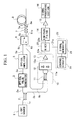
- FIG. 3 is a block diagram illustrating the structure of an optical-fiber characteristics measuring apparatus according to the related art. The operation of this optical-fiber characteristics measuring apparatus will be described below. When a
light source 31 emitscoherent light 31a of a frequency f0 to an opticaldirectional coupler 32, thecoherent light 31a passes through the opticaldirectional coupler 32 and enters anoptical pulse generator 33 ascoherent light 32a. Theoptical pulse generator 33 converts thiscoherent light 32a intopulse light 33a. It is to be noted that thecoherent light 32a and thepulse light 33a have the same frequency as the frequency f0 of thecoherent light 31a. - Next, an
optical frequency converter 34 performs frequency conversion by shifting the frequency of thepulse light 33a by a predetermined frequency Δ f and sends outcoherent light 34a having a frequency "f0 + Δf". Thispulse light 34a travels through anoptical amplifier 35, anoptical switch 36 and anoptical connector 37 and is emitted aspulse light 37a toward anoptical fiber 38 to be measured. When thispulse light 37a enters the to-be-measuredoptical fiber 38, reflection or scattering respectively produces reflected light or scattered light in accordance with the state in the to-be-measuredoptical fiber 38. Part of the reflected light or scattered light travels as returnedlight 38a through theoptical connector 37 and theoptical switch 36. Then, returnedlight 36b is emitted toward the balanced-light reception circuit 40. - The balanced-
light reception circuit 40 converts the returnedlight 36b into an electric signal through balanced-light reception with thecoherent light 32b of the frequency f0 emitted from the opticaldirectional coupler 32. Specifically, an opticaldirectional coupler 41 combines thecoherent light 32b and the returnedlight 36b, and aphotoelectric converter 42 converts the combined optical signal into an electric signal which is in turn amplified by anelectric signal 43a by anamplifier section 43. Thiselectric signal 43a is input to asignal processing section 46 through a low-pass filter 44 and anamplifier section 45. Thesignal processing section 46 acquires various characteristics of the to-be-measuredoptical fiber 38 based on the input electric signal and processes this electric signal on the time axis to prepare the distribution on the distance axis of the to-be-measuredoptical fiber 38. - According to the conventional optical-fiber characteristics measuring apparatus, as apparent from the above, the optical scheme using the
optical frequency converter 34 shifts the frequency of thepulse light 37a to be input to the to-be-measuredoptical fiber 38 by the predetermined frequency Δf with respect to the frequency of thecoherent light 31a. Then, the local oscillation light (coherent light 32b) and the returnedlight 36b are combined, yielding a beat signal. The frequency Δ f is set in accordance with the frequency of thereturned light 36b in such a way that the frequency of the beat signal (i.e., the difference between the frequencies of the local oscillation light and the returned light) lies in an electrically processable range. Accordingly, backward scattered light, such as the Rayleigh scattered light and Brillouin scattered light, and reflected light, which is produced in the to-be-measuredoptical fiber 38, can be detected as returned light. - The use of such an optical frequency conversion scheme requires that the
optical frequency converter 34 should be constituted by an optical frequency shifter or by an optical ring comprising several optical components. This complicates the structure of the optical-fiber characteristics measuring apparatus. When an optical ring system is used, for example, while pulse light is travels along the optical ring, new pulse light cannot be input to the optical ring. This restricts the cycle period of the pulse light that is emitted from the optical ring, thus disabling fast measuring of the characteristics of the to-be-measured optical fiber. In addition, the frequency conversion increases the frequency of the pulse light, thereby restricting the pulse width of the pulse light. - Accordingly, it is an object of the present invention to provide an optical-fiber characteristics measuring apparatus that has a simple structure which does not require frequency conversion of pulse light to be input an optical fiber to be measured and does not restrict the cycle period of the pulse light, thereby ensuring fast measuring of the characteristics of the optical fiber using a fast optical output.
- To achieve the above object, according to one aspect of this invention, there is provided an optical-fiber characteristics measuring apparatus for converting coherent light into pulse light, emitting the pulse light to an optical fiber, converting an optical signal acquired by balanced-light reception of returned light from the optical fiber and the coherent light into a first electric signal, and obtaining characteristics of the optical fiber from a frequency component of the returned light included in the first electric signal, which apparatus comprises signal generation means for generating a second electric signal having a frequency approximately coincident with a frequency of an optical signal to be detected in those optical signals included in the returned light; and mixing means for mixing the first electric signal and the second electric signal to thereby detect a frequency component of the optical signal to be detected.
- According to this invention, as specifically described above, the frequency component of the desired optical signal is detected by producing a first electric signal by conversion of the optical signal that is acquired by the balanced-light reception of returned light and coherent light, producing a second electric signal whose frequency approximately matches with the frequency of the optical signal to be detected of optical signals included in returned light, and then mixing the first and second electric signals together. In the case of detecting the returned light by using a beat signal obtained by combining the returned light and local oscillation light (coherent light), therefore, the frequency component of the optical signal included in the returned light can be detected even if the frequency band of the signal processor for acquiring the characteristics of an optical fiber is not matched with the frequency component of the beat signal. This can ensure excellent coherent detection according to the frequency component of reflected light or any of various kinds of scattered lights contained in the returned light. Further, it is unnecessary to shift the frequency of the pulse light to be sent to an optical fiber, thus eliminating the need for a circuit, such as an optical frequency shifter or an optical ring system. This can help make the structure of the optical-fiber characteristics measuring apparatus simpler. Furthermore, there is no restriction on the cycle period of pulse light, so that the pulse light can be emitted in a shorter period, thereby ensuring fast measuring of the characteristics of the optical fiber.
- In this optical-fiber characteristics measuring apparatus, the signal generation means may detect a spectrum of the optical signal to be detected by changing the frequency of the second electric signal over a spectrum width of the optical signal to be detected.
- In this case, the spectrum of the optical signal to be detected is detected by changing the frequency of the second electric signal over the spectrum width of the to-be-detected optical signal. Therefore, even if the spectrum width of an optical signal contained in the returned light is wider than the spectrum width of the second electric signal as in the case of scattered light, therefore, the spectrum of every optical signal contained in the returned light can be detected.
- Furthermore, in this case or in the optical-fiber characteristics measuring apparatus of the above aspect, the signal generation means may set the frequency of the second electric signal in accordance with a type of the optical signal to be detected.
-
- FIG. 1 is a block diagram illustrating the structure of an optical-fiber characteristics measuring apparatus according to one embodiment of the present invention;
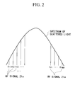
- FIG. 2 is an explanatory diagram showing the frequency, fr, of an RF signal to be set with respect to the spectrum of scattered light; and
- FIG. 3 is a block diagram illustrating the structure of an optical-fiber characteristics measuring apparatus according to the related art.
-
- One preferred embodiment of the present invention will now be described with reference to the accompanying drawings. FIG. 1 is a block diagram illustrating the structure of an optical-fiber characteristics measuring apparatus according to this embodiment of this invention.
- In this embodiment, a light source 1 is an MQW-DFB (Multiple Quantum Well-Distribution FeedBack) semiconductor laser or the like of the 1.5 µm band, which emits coherent light la having a narrow band. The continuous light emitted from the light source 1 has a frequency f0. A 1 x 2 optical
directional coupler 2 has one input port and two output ports. This opticaldirectional coupler 2 separates the coherent light la entering the input port into two components and respectively outputs them ascoherent lights - An
optical pulse generator 3 is an E/O (Electric/Optical) switch or the like and converts thecoherent light 2a intopulse light 3a having a pulse width of several nanoseconds to several microseconds through the ON/OFF action of that switch. The period of generating thispulse light 3a depends on the length of anoptical fiber 8 to be measured (i.e., the distance range). For example, the generation period of thepulse light 3a is 200 µ sec for the distance range of 10 km and is 20 µ sec for the distance range of 1km. - An optical amplifier 5 is an optical fiber amplifier, which uses an Er (Erbium) doped fiber, or the like. This optical amplifier 5 amplifies the
incident pulse light 3a to a predetermined level and outputs the amplified light. Anoptical switch 6, which is an optical circulator or the like, sendspulse light 5a, input to itsinput port 6i, to an optical connector 7 ascoherent light 6a from an output/input port 6io. Theoptical switch 6 also outputs returned light, which enters the output/input port 6io via the optical connector 7 from the to-be-measuredoptical fiber 8, from an output port 6o as returnedlight 6b. - Of the optical signals contained in the returned light, the Brillouin scattered light has a frequency shift of about 9 to 12 GHz with respect to the frequency f0 of the pulse light input to the to-be-measured
optical fiber 8. That is, with fs being the frequency shift, the frequency, fb, of thereturned light 6b or returnedlight 8a becomes "f0 - fs". With regard to the Rayleigh scattered light or reflected light, the frequency shift fs is "0", so that the frequency fb (= f0 - fs) is equal to the frequency f0. - The individual constituent sections of a balanced-
light reception circuit 10 will now be discussed. An opticaldirectional coupler 11 combines thecoherent light 2b of the frequency f0 sent from the opticaldirectional coupler 2 and the returnedlight 6b of the frequency fb (= f0 - fs). The frequency components of anoptical signal 11a which is acquired by the light combination are f0 ± (f0 - fs), that is, 2f0 - fs or fs. Anphotoelectric converter 12 converts thisoptical signal 11a into aelectric signal 12a. Anamplifier section 13 amplifies theelectric signal 12a to a level suitable for a mixer 23 (to be discussed later) to process, and outputs a resultantelectric signal 13a. - The individual constituent sections of a
signal generation section 20 will now be discussed. Asignal generator 21 generates an RF (Radio Frequency)signal 21a having a sinusoidal wave or the like. Acontrol circuit 22 sets the frequency, fr, of thisRF signal 21a. The set value of the frequency fr varies depending on an optical signal to be detected in the returned light; for example, the frequency fr is set to approximately 8 to 12 GHz in a case of detecting the Brillouin scattered light and is set to approximately 10 kHz in a case of detecting the Rayleigh scattered light or reflected light. - The
mixer 23 mixes theelectric signal 13a output from the balanced-light reception circuit 10 with theRF signal 21a output from thesignal generation section 20 and outputs anelectric signal 23a which is theelectric signal 13a whose frequency is lowered by the frequency fr of theRF signal 21a. As the frequency fr of theRF signal 21a is set close to the frequency shift fs of the returned light, of the above four frequency components, the frequency component that is acquired by lowering the frequency shift fs by the frequency fr approaches a DC component. This frequency component therefore lies in a frequency range which is easily processable by electric circuits (specifically, a low-pass filter 14, anamplifier section 15 and a signal processing section 16) located at the subsequent stage of themixer 23. - The low-
pass filter 14 eliminates a high-frequency component, such as noise, from theelectric signal 23a output from themixer 23, thereby improving the S/N (Signal/Noise) ratio. Theamplifier section 15 amplifies the electric signal output from the low-pass filter 14 to a level suitable for thesignal processing section 16 to process. Thesignal processing section 16 has various capabilities for performing various kinds of signal processing, such as addition of the electric signal output from theamplifier section 15. With those capabilities, thesignal processing section 16 carries out averaging of the input electric signals to acquire the deformation and loss of the to-be-measuredoptical fiber 8 and detects the returned light on the time axis to acquire the distance distribution of the deformation characteristic and optical loss characteristic. - A description will now be given of the operation of the thus constituted optical-fiber characteristics measuring apparatus. When the light source 1 emits the coherent light of the frequency f0, the optical
directional coupler 2 branches the coherent light la into two directions and sends onecoherent light 2b to the balanced-light reception circuit 10. Theoptical pulse generator 3 converts thecoherent light 2a to thepulse light 3a and sends thepulse light 3a to the optical amplifier 5. The optical amplifier 5 sends thepulse light 5a, acquired by amplifying thepulse light 3a, to theinput port 6i of theoptical switch 6. Theoptical switch 6 sends theinput pulse light 5a as thepulse light 6a to the optical connector 7. The optical connector 7 sends the receivedpulse light 6a as thepulse light 7a to the to-be-measuredoptical fiber 8. Unlike in the related art, the frequency of thepulse light 7a has not undergone any frequency shifting and is the same as the frequency fo of thecoherent light 2a. - When this
pulse light 7a enters the to-be-measuredoptical fiber 8, light reflection or scattering occurs in accordance with the state of the to-be-measuredoptical fiber 8, yielding reflected light or scattered light. Part of the reflected light or scattered light returns to the optical connector 7 as the returned light 8a. Because the returned light 8a undergoes a specific frequency shift fs in the scattering phenomenon as mentioned above, the frequency fb of the returned light 8a becomes f0 - fs. Then returned light 8a is then sent out from the output/input port 6io of theoptical switch 6 after passing through the optical connector 7, and enters the balanced-light reception circuit 10 as the returned light 6b. - In the balanced-
light reception circuit 10, the opticaldirectional coupler 11 combines thecoherent light 2b of the frequency f0 and the returned light 6b of the frequency fb, and thephotoelectric converter 12 converts theresultant pulse light 11a into theelectric signal 12a. As mentioned above, the frequency components contained in theelectric signal 12a become f0 ± fb (= f0 ± (f0 - fs)). Theamplifier section 13 sends theelectric signal 13a, obtained by amplifying theelectric signal 12a, to themixer 23. Meanwhile, thecontrol circuit 22 in thesignal generation section 20 controls thesignal generator 21 to set the frequency fr of theRF signal 21a sent to themixer 23 to the same frequency as the frequency shift fs. At this time, thecontrol circuit 22 sets the value of the frequency fr in accordance with the frequency shift fs that varies depending on the optical signal to be detected (the Rayleigh scattered light, the Brillouin scattered light, the reflected light or the like). - Next, as the
mixer 23 mixes theelectric signal 13a with theRF signal 21a to lower the frequency of theelectric signal 13a by the frequency fr, only the frequency component of the frequency shift fs is reduced close to the DC component. This yields theelectric signal 23a which contains only the frequency component equivalent to the pulse width of thepulse light 3a. That is, of the four frequency components contained in theelectric signal 13a, only the frequency component of the frequency f0 - fb (= fs) is detected, so that the electric circuits located at the subsequent stage of themixer 23 can process only the electric signal that is equivalent to the returned light produced in the to-be-measuredoptical fiber 8. Then, the low-pass filter 14 eliminates the high-frequency component from theelectric signal 23a and sends the resultant signal to theamplifier section 15. Theamplifier section 15 amplifies the output signal of the low-pass filter 14 and sends the amplified signal to thesignal processing section 16. As mentioned earlier, thesignal processing section 16 acquires the deformation characteristic and optical loss characteristic associated with the to-be-measuredoptical fiber 8 and the distance distribution of those characteristics. - As in a case of scattered light, the spectrum width of the returned light 6b or 8a may become wider than the spectrum width of the
RF signal 21a. In this case, thecontrol circuit 22 controls thesignal generator 21 to sequentially change the frequency fr of theRF signal 21a in a predetermined range in an order of fr1, fr2, fr3 fm, ..., then to frmax as illustrated in FIG. 2. The spectrum of every returned light from the to-be-measuredoptical fiber 8 can be detected by detecting the electric signal of each of those frequencies in association with this frequency change by means of thesignal processing section 16.
Claims (3)
- An optical-fiber characteristics measuring apparatus comprising:a light source (1) that emits coherent light (1a and 2a);an optical pulse generator (3) that converts the coherent light (2a) into pulse light (3a) and emits the pulse light into an optical fiber (8);an optical coupler (11) that mixes the coherent light (2b) generated by the light source (1) and returned light (6b) from the optical fiber (8) and outputs mixed optical signal (11a);a photoelectric converter (12) that converts the mixed optical signal (11a) into a first electric signal (12a);a signal generator (20) that generates a second electric signal (21a) having a frequency corresponding to a frequency of an optical signal to be detected included in the returned light (6b);a mixer that mixes the first electric signal and the second electric signal to detect a frequency component of the optical signal to be detected; anda signal processor that evaluates characteristics of the optical fiber from the frequency component of the optical signal to be detected.
- An optical-fiber characteristics measuring apparatus according to claim 1, wherein the signal generator (20) detects a spectrum of the optical signal to be detected by changing the frequency of the second electric signal (21a) over a spectrum width of the optical signal to be detected.
- An optical-fiber characteristics measuring apparatus according to claim 1, wherein the signal generator (20) controls the frequency of the second electric signal (21a) in accordance with a type of the optical signal to be detected.
Applications Claiming Priority (2)
| Application Number | Priority Date | Filing Date | Title |
|---|---|---|---|
| JP10715599A JP3481494B2 (en) | 1999-04-14 | 1999-04-14 | Optical fiber characteristics measurement device |
| JP10715599 | 1999-04-14 |
Publications (3)
| Publication Number | Publication Date |
|---|---|
| EP1045237A2 true EP1045237A2 (en) | 2000-10-18 |
| EP1045237A3 EP1045237A3 (en) | 2002-03-06 |
| EP1045237B1 EP1045237B1 (en) | 2009-02-18 |
Family
ID=14451910
Family Applications (1)
| Application Number | Title | Priority Date | Filing Date |
|---|---|---|---|
| EP00400999A Expired - Lifetime EP1045237B1 (en) | 1999-04-14 | 2000-04-11 | Optical fiber characteristics measuring apparatus |
Country Status (4)
| Country | Link |
|---|---|
| US (1) | US6335788B1 (en) |
| EP (1) | EP1045237B1 (en) |
| JP (1) | JP3481494B2 (en) |
| DE (1) | DE60041565D1 (en) |
Cited By (2)
| Publication number | Priority date | Publication date | Assignee | Title |
|---|---|---|---|---|
| WO2008040939A2 (en) * | 2006-10-06 | 2008-04-10 | Schlumberger Holdings Limited | Measuring brillouin backscatter from an optical fibre using a tracking signal |
| WO2008105322A1 (en) | 2007-02-28 | 2008-09-04 | Nippon Telegraph And Telephone Corporation | Optical refractometry measuring method and device |
Families Citing this family (15)
| Publication number | Priority date | Publication date | Assignee | Title |
|---|---|---|---|---|
| JP4504789B2 (en) * | 2004-11-11 | 2010-07-14 | 日本電信電話株式会社 | Optical communication system and optical test apparatus |
| JP4826747B2 (en) * | 2006-02-24 | 2011-11-30 | 横河電機株式会社 | Method for measuring frequency shift of Brillouin scattered light and apparatus using the same |
| US20070253630A1 (en) * | 2006-04-26 | 2007-11-01 | International Business Machines Corporation | Method and apparatus for fast and flexible digital image compression using programmable sprite buffer |
| JP5168839B2 (en) * | 2006-07-31 | 2013-03-27 | 横河電機株式会社 | Optical fiber characteristic measuring device |
| GB2440952B (en) * | 2006-08-16 | 2009-04-08 | Schlumberger Holdings | Measuring brillouin backscatter from an optical fibre using digitisation |
| GB2441154B (en) * | 2006-08-24 | 2009-02-18 | Schlumberger Holdings | Measuring brillouin backscatter from an optical fibre using channelisation |
| JP5122120B2 (en) | 2006-12-13 | 2013-01-16 | 横河電機株式会社 | Optical fiber characteristic measuring device |
| US7504618B2 (en) * | 2007-07-03 | 2009-03-17 | Schlumberger Technology Corporation | Distributed sensing in an optical fiber using brillouin scattering |
| EP2215752B1 (en) * | 2007-09-28 | 2013-09-25 | Telefonaktiebolaget L M Ericsson (PUBL) | Optical amplifier |
| US20100318071A1 (en) * | 2009-06-10 | 2010-12-16 | Tyco Healthcare Group Lp | Fluid Collection Canister Including Canister Top with Filter Membrane and Negative Pressure Wound Therapy Systems Including Same |
| CN104596357B (en) * | 2013-11-01 | 2017-10-27 | 上海机电工程研究所 | Radio frequency/optics HWIL simulation complex target simulation system |
| JP6288013B2 (en) * | 2015-09-07 | 2018-03-07 | 横河電機株式会社 | Optical fiber characteristic measuring device |
| JP2019215168A (en) * | 2018-06-11 | 2019-12-19 | 日本電信電話株式会社 | Light pulse test device and light pulse test method |
| JP6814180B2 (en) * | 2018-07-02 | 2021-01-13 | 日本電信電話株式会社 | Distributed optical fiber vibration measuring device and distributed optical fiber vibration measuring method |
| US11391622B2 (en) * | 2019-02-06 | 2022-07-19 | Nec Corporation | Optical fiber sensing system with reduced spatial resolution and noise for multiple application uses |
Citations (1)
| Publication number | Priority date | Publication date | Assignee | Title |
|---|---|---|---|---|
| EP0889312A2 (en) | 1997-06-30 | 1999-01-07 | Ando Electric Co., Ltd. | Apparatus for measuring characteristics of optical fiber |
Family Cites Families (4)
| Publication number | Priority date | Publication date | Assignee | Title |
|---|---|---|---|---|
| DE3609371A1 (en) * | 1986-03-20 | 1987-09-24 | Philips Patentverwaltung | OPTICAL TIME AREA REFLECTOR WITH HETERODYN RECEPTION |
| JP2977091B2 (en) * | 1990-09-28 | 1999-11-10 | 安藤電気株式会社 | Optical pulse tester using heterodyne light reception |
| JP3033677B2 (en) * | 1995-09-26 | 2000-04-17 | 安藤電気株式会社 | Optical fiber characteristics measurement device |
| JP3394902B2 (en) * | 1998-02-20 | 2003-04-07 | アンリツ株式会社 | Chromatic dispersion measuring device and polarization dispersion measuring device |
-
1999
- 1999-04-14 JP JP10715599A patent/JP3481494B2/en not_active Expired - Lifetime
-
2000
- 2000-04-11 US US09/547,063 patent/US6335788B1/en not_active Expired - Lifetime
- 2000-04-11 DE DE60041565T patent/DE60041565D1/en not_active Expired - Lifetime
- 2000-04-11 EP EP00400999A patent/EP1045237B1/en not_active Expired - Lifetime
Patent Citations (1)
| Publication number | Priority date | Publication date | Assignee | Title |
|---|---|---|---|---|
| EP0889312A2 (en) | 1997-06-30 | 1999-01-07 | Ando Electric Co., Ltd. | Apparatus for measuring characteristics of optical fiber |
Non-Patent Citations (1)
| Title |
|---|
| "lightwave technology", IEEE. NEW YORK, US, vol. 12, no. 7, 1 July 1994 (1994-07-01), pages 1230 - 1238 |
Cited By (7)
| Publication number | Priority date | Publication date | Assignee | Title |
|---|---|---|---|---|
| WO2008040939A2 (en) * | 2006-10-06 | 2008-04-10 | Schlumberger Holdings Limited | Measuring brillouin backscatter from an optical fibre using a tracking signal |
| WO2008040939A3 (en) * | 2006-10-06 | 2008-10-09 | Schlumberger Holdings | Measuring brillouin backscatter from an optical fibre using a tracking signal |
| WO2008105322A1 (en) | 2007-02-28 | 2008-09-04 | Nippon Telegraph And Telephone Corporation | Optical refractometry measuring method and device |
| EP2128588A1 (en) * | 2007-02-28 | 2009-12-02 | Nippon Telegraph and Telephone Corporation | Optical refractometry measuring method and device |
| EP2128588A4 (en) * | 2007-02-28 | 2010-09-15 | Nippon Telegraph & Telephone | Optical refractometry measuring method and device |
| EP2339316A1 (en) | 2007-02-28 | 2011-06-29 | Nippon Telegraph And Telephone Corporation | Optical reflectometry and optical reflectometer |
| US8149419B2 (en) | 2007-02-28 | 2012-04-03 | Nippon Telegraph And Telephone Corporation | Optical reflectometry and optical reflectometer |
Also Published As
| Publication number | Publication date |
|---|---|
| JP3481494B2 (en) | 2003-12-22 |
| EP1045237A3 (en) | 2002-03-06 |
| US6335788B1 (en) | 2002-01-01 |
| EP1045237B1 (en) | 2009-02-18 |
| JP2000298077A (en) | 2000-10-24 |
| DE60041565D1 (en) | 2009-04-02 |
Similar Documents
| Publication | Publication Date | Title |
|---|---|---|
| EP1045237A2 (en) | Optical fiber characteristics measuring apparatus | |
| US6700655B2 (en) | Optical fiber characteristic measuring device | |
| US7873273B2 (en) | Apparatus for measuring the characteristics of an optical fiber | |
| US7580132B2 (en) | Optical device for measuring a doppler frequency shift | |
| US20010050768A1 (en) | Optical fiber distortion measurement device | |
| US7423736B2 (en) | Low-cost doppler frequency shift measuring device | |
| CN113702993A (en) | Multi-wavelength multi-modulation frequency modulation continuous wave laser range radar | |
| US5764359A (en) | Laser linewidth measuring apparatus utilizing stimulated brillouin scattering | |
| CN113346948A (en) | Ultralow phase noise detection technology based on millimeter wave signal generated by optical frequency comb | |
| WO2004061476A1 (en) | Laser radar apparatus | |
| CN101881833A (en) | Electro-optical distance measurement device | |
| JP3282135B2 (en) | Optical frequency domain reflectometer | |
| Hirsch et al. | Amplitude modulated heterodyne reflectometer for density profile and density fluctuation profile measurements at W7‐AS | |
| CN113014313A (en) | Optical time domain reflectometer | |
| CN114167440B (en) | Coherent frequency modulation continuous wave distance measurement method and system based on phase noise compensation | |
| WO2023131624A1 (en) | Optical measurement system | |
| US6697148B1 (en) | Optical radar with range and doppler measurement capability | |
| JPH05322695A (en) | Light pulse tester | |
| JP7424360B2 (en) | Optical fiber characteristic measuring device and optical fiber characteristic measuring method | |
| CN219370000U (en) | Optical path for eliminating echo interference of transmitting end face of FMCW optical fiber laser radar | |
| JP2003139651A (en) | Method and apparatus for detection of light signal | |
| JP3453746B2 (en) | Optical fiber inspection equipment | |
| JPH05243663A (en) | Botda for maintaining frequency differency of both light sources constant | |
| JPH06347225A (en) | Apparatus for measuring distortion distribution of optical fiber | |
| JP2825203B2 (en) | Photodetector test device and network analyzer |
Legal Events
| Date | Code | Title | Description |
|---|---|---|---|
| PUAI | Public reference made under article 153(3) epc to a published international application that has entered the european phase |
Free format text: ORIGINAL CODE: 0009012 |
|
| AK | Designated contracting states |
Kind code of ref document: A2 Designated state(s): DE FR GB Kind code of ref document: A2 Designated state(s): AT BE CH CY DE DK ES FI FR GB GR IE IT LI LU MC NL PT SE |
|
| AX | Request for extension of the european patent |
Free format text: AL;LT;LV;MK;RO;SI |
|
| PUAL | Search report despatched |
Free format text: ORIGINAL CODE: 0009013 |
|
| AK | Designated contracting states |
Kind code of ref document: A3 Designated state(s): AT BE CH CY DE DK ES FI FR GB GR IE IT LI LU MC NL PT SE |
|
| AX | Request for extension of the european patent |
Free format text: AL;LT;LV;MK;RO;SI |
|
| 17P | Request for examination filed |
Effective date: 20020704 |
|
| AKX | Designation fees paid |
Free format text: DE FR GB |
|
| RAP1 | Party data changed (applicant data changed or rights of an application transferred) |
Owner name: YOKOGAWA ELECTRIC CORPORATION Owner name: NIPPON TELEGRAPH AND TELEPHONE CORPORATION |
|
| 17Q | First examination report despatched |
Effective date: 20080429 |
|
| GRAC | Information related to communication of intention to grant a patent modified |
Free format text: ORIGINAL CODE: EPIDOSCIGR1 |
|
| GRAP | Despatch of communication of intention to grant a patent |
Free format text: ORIGINAL CODE: EPIDOSNIGR1 |
|
| GRAS | Grant fee paid |
Free format text: ORIGINAL CODE: EPIDOSNIGR3 |
|
| GRAA | (expected) grant |
Free format text: ORIGINAL CODE: 0009210 |
|
| AK | Designated contracting states |
Kind code of ref document: B1 Designated state(s): DE FR GB |
|
| REG | Reference to a national code |
Ref country code: GB Ref legal event code: FG4D |
|
| REF | Corresponds to: |
Ref document number: 60041565 Country of ref document: DE Date of ref document: 20090402 Kind code of ref document: P |
|
| PLBE | No opposition filed within time limit |
Free format text: ORIGINAL CODE: 0009261 |
|
| STAA | Information on the status of an ep patent application or granted ep patent |
Free format text: STATUS: NO OPPOSITION FILED WITHIN TIME LIMIT |
|
| REG | Reference to a national code |
Ref country code: FR Ref legal event code: ST Effective date: 20091231 |
|
| 26N | No opposition filed |
Effective date: 20091119 |
|
| GBPC | Gb: european patent ceased through non-payment of renewal fee |
Effective date: 20090518 |
|
| PG25 | Lapsed in a contracting state [announced via postgrant information from national office to epo] |
Ref country code: FR Free format text: LAPSE BECAUSE OF NON-PAYMENT OF DUE FEES Effective date: 20091222 |
|
| PG25 | Lapsed in a contracting state [announced via postgrant information from national office to epo] |
Ref country code: GB Free format text: LAPSE BECAUSE OF NON-PAYMENT OF DUE FEES Effective date: 20090518 |
|
| PGFP | Annual fee paid to national office [announced via postgrant information from national office to epo] |
Ref country code: DE Payment date: 20120425 Year of fee payment: 13 |
|
| PG25 | Lapsed in a contracting state [announced via postgrant information from national office to epo] |
Ref country code: DE Free format text: LAPSE BECAUSE OF NON-PAYMENT OF DUE FEES Effective date: 20131101 |
|
| REG | Reference to a national code |
Ref country code: DE Ref legal event code: R119 Ref document number: 60041565 Country of ref document: DE Effective date: 20131101 |