EP1041573A2 - Appareil de lecture et méthode de lecture - Google Patents
Appareil de lecture et méthode de lecture Download PDFInfo
- Publication number
- EP1041573A2 EP1041573A2 EP00301733A EP00301733A EP1041573A2 EP 1041573 A2 EP1041573 A2 EP 1041573A2 EP 00301733 A EP00301733 A EP 00301733A EP 00301733 A EP00301733 A EP 00301733A EP 1041573 A2 EP1041573 A2 EP 1041573A2
- Authority
- EP
- European Patent Office
- Prior art keywords
- file
- reproduction
- information
- data
- area
- Prior art date
- Legal status (The legal status is an assumption and is not a legal conclusion. Google has not performed a legal analysis and makes no representation as to the accuracy of the status listed.)
- Granted
Links
- 238000000034 method Methods 0.000 title claims description 83
- 238000005242 forging Methods 0.000 claims abstract description 32
- 238000004364 calculation method Methods 0.000 claims description 5
- 230000015654 memory Effects 0.000 description 115
- 230000006870 function Effects 0.000 description 77
- 230000008569 process Effects 0.000 description 69
- 238000010586 diagram Methods 0.000 description 50
- 238000003860 storage Methods 0.000 description 25
- 238000006243 chemical reaction Methods 0.000 description 14
- 238000013478 data encryption standard Methods 0.000 description 14
- 238000005192 partition Methods 0.000 description 12
- 230000005236 sound signal Effects 0.000 description 9
- 238000012937 correction Methods 0.000 description 7
- 102100022441 Sperm surface protein Sp17 Human genes 0.000 description 5
- 238000005070 sampling Methods 0.000 description 4
- 230000007547 defect Effects 0.000 description 3
- 238000009826 distribution Methods 0.000 description 3
- 230000002159 abnormal effect Effects 0.000 description 2
- 230000002457 bidirectional effect Effects 0.000 description 2
- 230000005540 biological transmission Effects 0.000 description 2
- 230000008859 change Effects 0.000 description 2
- 230000006835 compression Effects 0.000 description 2
- 238000007906 compression Methods 0.000 description 2
- 238000004590 computer program Methods 0.000 description 2
- 230000001955 cumulated effect Effects 0.000 description 2
- 230000007423 decrease Effects 0.000 description 2
- 239000006185 dispersion Substances 0.000 description 2
- 238000004519 manufacturing process Methods 0.000 description 2
- 230000003287 optical effect Effects 0.000 description 2
- 238000011084 recovery Methods 0.000 description 2
- 230000003068 static effect Effects 0.000 description 2
- 102100021391 Cationic amino acid transporter 3 Human genes 0.000 description 1
- 101000894420 Homo sapiens Cationic amino acid transporter 3 Proteins 0.000 description 1
- 235000016496 Panda oleosa Nutrition 0.000 description 1
- 240000000220 Panda oleosa Species 0.000 description 1
- 230000003044 adaptive effect Effects 0.000 description 1
- 238000007792 addition Methods 0.000 description 1
- 230000001174 ascending effect Effects 0.000 description 1
- 230000007175 bidirectional communication Effects 0.000 description 1
- 230000006854 communication Effects 0.000 description 1
- 238000004891 communication Methods 0.000 description 1
- 125000004122 cyclic group Chemical group 0.000 description 1
- 230000002950 deficient Effects 0.000 description 1
- 238000001514 detection method Methods 0.000 description 1
- 230000006866 deterioration Effects 0.000 description 1
- 230000009977 dual effect Effects 0.000 description 1
- 238000009413 insulation Methods 0.000 description 1
- 230000010354 integration Effects 0.000 description 1
- 230000007246 mechanism Effects 0.000 description 1
- 201000002266 mite infestation Diseases 0.000 description 1
- 230000004048 modification Effects 0.000 description 1
- 238000012986 modification Methods 0.000 description 1
- 238000012545 processing Methods 0.000 description 1
- 230000002035 prolonged effect Effects 0.000 description 1
- 230000001360 synchronised effect Effects 0.000 description 1
Images


Classifications
-
- G—PHYSICS
- G11—INFORMATION STORAGE
- G11C—STATIC STORES
- G11C16/00—Erasable programmable read-only memories
- G11C16/02—Erasable programmable read-only memories electrically programmable
- G11C16/06—Auxiliary circuits, e.g. for writing into memory
- G11C16/22—Safety or protection circuits preventing unauthorised or accidental access to memory cells
-
- G—PHYSICS
- G06—COMPUTING; CALCULATING OR COUNTING
- G06F—ELECTRIC DIGITAL DATA PROCESSING
- G06F16/00—Information retrieval; Database structures therefor; File system structures therefor
- G06F16/10—File systems; File servers
-
- G—PHYSICS
- G06—COMPUTING; CALCULATING OR COUNTING
- G06F—ELECTRIC DIGITAL DATA PROCESSING
- G06F21/00—Security arrangements for protecting computers, components thereof, programs or data against unauthorised activity
- G06F21/10—Protecting distributed programs or content, e.g. vending or licensing of copyrighted material ; Digital rights management [DRM]
-
- G—PHYSICS
- G06—COMPUTING; CALCULATING OR COUNTING
- G06F—ELECTRIC DIGITAL DATA PROCESSING
- G06F21/00—Security arrangements for protecting computers, components thereof, programs or data against unauthorised activity
- G06F21/30—Authentication, i.e. establishing the identity or authorisation of security principals
- G06F21/44—Program or device authentication
- G06F21/445—Program or device authentication by mutual authentication, e.g. between devices or programs
-
- G—PHYSICS
- G06—COMPUTING; CALCULATING OR COUNTING
- G06F—ELECTRIC DIGITAL DATA PROCESSING
- G06F21/00—Security arrangements for protecting computers, components thereof, programs or data against unauthorised activity
- G06F21/60—Protecting data
- G06F21/602—Providing cryptographic facilities or services
-
- G—PHYSICS
- G06—COMPUTING; CALCULATING OR COUNTING
- G06F—ELECTRIC DIGITAL DATA PROCESSING
- G06F21/00—Security arrangements for protecting computers, components thereof, programs or data against unauthorised activity
- G06F21/70—Protecting specific internal or peripheral components, in which the protection of a component leads to protection of the entire computer
- G06F21/71—Protecting specific internal or peripheral components, in which the protection of a component leads to protection of the entire computer to assure secure computing or processing of information
- G06F21/72—Protecting specific internal or peripheral components, in which the protection of a component leads to protection of the entire computer to assure secure computing or processing of information in cryptographic circuits
-
- G—PHYSICS
- G11—INFORMATION STORAGE
- G11B—INFORMATION STORAGE BASED ON RELATIVE MOVEMENT BETWEEN RECORD CARRIER AND TRANSDUCER
- G11B20/00—Signal processing not specific to the method of recording or reproducing; Circuits therefor
- G11B20/00086—Circuits for prevention of unauthorised reproduction or copying, e.g. piracy
- G11B20/0021—Circuits for prevention of unauthorised reproduction or copying, e.g. piracy involving encryption or decryption of contents recorded on or reproduced from a record carrier
- G11B20/00217—Circuits for prevention of unauthorised reproduction or copying, e.g. piracy involving encryption or decryption of contents recorded on or reproduced from a record carrier the cryptographic key used for encryption and/or decryption of contents recorded on or reproduced from the record carrier being read from a specific source
- G11B20/00246—Circuits for prevention of unauthorised reproduction or copying, e.g. piracy involving encryption or decryption of contents recorded on or reproduced from a record carrier the cryptographic key used for encryption and/or decryption of contents recorded on or reproduced from the record carrier being read from a specific source wherein the key is obtained from a local device, e.g. device key initially stored by the player or by the recorder
-
- G—PHYSICS
- G11—INFORMATION STORAGE
- G11B—INFORMATION STORAGE BASED ON RELATIVE MOVEMENT BETWEEN RECORD CARRIER AND TRANSDUCER
- G11B20/00—Signal processing not specific to the method of recording or reproducing; Circuits therefor
- G11B20/00086—Circuits for prevention of unauthorised reproduction or copying, e.g. piracy
- G11B20/0021—Circuits for prevention of unauthorised reproduction or copying, e.g. piracy involving encryption or decryption of contents recorded on or reproduced from a record carrier
- G11B20/00217—Circuits for prevention of unauthorised reproduction or copying, e.g. piracy involving encryption or decryption of contents recorded on or reproduced from a record carrier the cryptographic key used for encryption and/or decryption of contents recorded on or reproduced from the record carrier being read from a specific source
- G11B20/00253—Circuits for prevention of unauthorised reproduction or copying, e.g. piracy involving encryption or decryption of contents recorded on or reproduced from a record carrier the cryptographic key used for encryption and/or decryption of contents recorded on or reproduced from the record carrier being read from a specific source wherein the key is stored on the record carrier
- G11B20/00297—Circuits for prevention of unauthorised reproduction or copying, e.g. piracy involving encryption or decryption of contents recorded on or reproduced from a record carrier the cryptographic key used for encryption and/or decryption of contents recorded on or reproduced from the record carrier being read from a specific source wherein the key is stored on the record carrier the key being stored in a management area, e.g. the video manager [VMG] of a DVD
-
- G—PHYSICS
- G11—INFORMATION STORAGE
- G11B—INFORMATION STORAGE BASED ON RELATIVE MOVEMENT BETWEEN RECORD CARRIER AND TRANSDUCER
- G11B20/00—Signal processing not specific to the method of recording or reproducing; Circuits therefor
- G11B20/00086—Circuits for prevention of unauthorised reproduction or copying, e.g. piracy
- G11B20/0021—Circuits for prevention of unauthorised reproduction or copying, e.g. piracy involving encryption or decryption of contents recorded on or reproduced from a record carrier
- G11B20/00485—Circuits for prevention of unauthorised reproduction or copying, e.g. piracy involving encryption or decryption of contents recorded on or reproduced from a record carrier characterised by a specific kind of data which is encrypted and recorded on and/or reproduced from the record carrier
- G11B20/00492—Circuits for prevention of unauthorised reproduction or copying, e.g. piracy involving encryption or decryption of contents recorded on or reproduced from a record carrier characterised by a specific kind of data which is encrypted and recorded on and/or reproduced from the record carrier wherein content or user data is encrypted
- G11B20/00507—Circuits for prevention of unauthorised reproduction or copying, e.g. piracy involving encryption or decryption of contents recorded on or reproduced from a record carrier characterised by a specific kind of data which is encrypted and recorded on and/or reproduced from the record carrier wherein content or user data is encrypted wherein consecutive physical data units of the record carrier are encrypted with separate encryption keys, e.g. the key changes on a cluster or sector basis
-
- G—PHYSICS
- G11—INFORMATION STORAGE
- G11B—INFORMATION STORAGE BASED ON RELATIVE MOVEMENT BETWEEN RECORD CARRIER AND TRANSDUCER
- G11B20/00—Signal processing not specific to the method of recording or reproducing; Circuits therefor
- G11B20/00086—Circuits for prevention of unauthorised reproduction or copying, e.g. piracy
- G11B20/00731—Circuits for prevention of unauthorised reproduction or copying, e.g. piracy involving a digital rights management system for enforcing a usage restriction
- G11B20/00746—Circuits for prevention of unauthorised reproduction or copying, e.g. piracy involving a digital rights management system for enforcing a usage restriction wherein the usage restriction can be expressed as a specific number
- G11B20/00753—Circuits for prevention of unauthorised reproduction or copying, e.g. piracy involving a digital rights management system for enforcing a usage restriction wherein the usage restriction can be expressed as a specific number wherein the usage restriction limits the number of copies that can be made, e.g. CGMS, SCMS, or CCI flags
-
- G—PHYSICS
- G11—INFORMATION STORAGE
- G11B—INFORMATION STORAGE BASED ON RELATIVE MOVEMENT BETWEEN RECORD CARRIER AND TRANSDUCER
- G11B20/00—Signal processing not specific to the method of recording or reproducing; Circuits therefor
- G11B20/00086—Circuits for prevention of unauthorised reproduction or copying, e.g. piracy
- G11B20/00731—Circuits for prevention of unauthorised reproduction or copying, e.g. piracy involving a digital rights management system for enforcing a usage restriction
- G11B20/0084—Circuits for prevention of unauthorised reproduction or copying, e.g. piracy involving a digital rights management system for enforcing a usage restriction wherein the usage restriction can be expressed as a specific time or date
-
- G—PHYSICS
- G11—INFORMATION STORAGE
- G11B—INFORMATION STORAGE BASED ON RELATIVE MOVEMENT BETWEEN RECORD CARRIER AND TRANSDUCER
- G11B20/00—Signal processing not specific to the method of recording or reproducing; Circuits therefor
- G11B20/10—Digital recording or reproducing
-
- G—PHYSICS
- G11—INFORMATION STORAGE
- G11C—STATIC STORES
- G11C16/00—Erasable programmable read-only memories
- G11C16/02—Erasable programmable read-only memories electrically programmable
- G11C16/06—Auxiliary circuits, e.g. for writing into memory
- G11C16/10—Programming or data input circuits
- G11C16/20—Initialising; Data preset; Chip identification
-
- G—PHYSICS
- G11—INFORMATION STORAGE
- G11C—STATIC STORES
- G11C7/00—Arrangements for writing information into, or reading information out from, a digital store
- G11C7/16—Storage of analogue signals in digital stores using an arrangement comprising analogue/digital [A/D] converters, digital memories and digital/analogue [D/A] converters
-
- G—PHYSICS
- G06—COMPUTING; CALCULATING OR COUNTING
- G06F—ELECTRIC DIGITAL DATA PROCESSING
- G06F2221/00—Indexing scheme relating to security arrangements for protecting computers, components thereof, programs or data against unauthorised activity
- G06F2221/21—Indexing scheme relating to G06F21/00 and subgroups addressing additional information or applications relating to security arrangements for protecting computers, components thereof, programs or data against unauthorised activity
- G06F2221/2107—File encryption
-
- G—PHYSICS
- G06—COMPUTING; CALCULATING OR COUNTING
- G06F—ELECTRIC DIGITAL DATA PROCESSING
- G06F2221/00—Indexing scheme relating to security arrangements for protecting computers, components thereof, programs or data against unauthorised activity
- G06F2221/21—Indexing scheme relating to G06F21/00 and subgroups addressing additional information or applications relating to security arrangements for protecting computers, components thereof, programs or data against unauthorised activity
- G06F2221/2137—Time limited access, e.g. to a computer or data
-
- G—PHYSICS
- G11—INFORMATION STORAGE
- G11C—STATIC STORES
- G11C2207/00—Indexing scheme relating to arrangements for writing information into, or reading information out from, a digital store
- G11C2207/16—Solid state audio
Definitions
- the present invention relates to a reproducing apparatus and a reproducing method, for example (though not exclusively) for checking forged information of a file recorded in a detachable memory card.
- EEPROM Electrically Erasable Programmable ROM
- EEPROM Electrically Erasable Programmable ROM
- flash memory that allows one bit to be accomplished with one transistor using all-bit-erase system has been developed.
- the flash memory is being expected as a successor of conventional record mediums such as magnetic disks and optical discs.
- a memory card using a flash memory is also known.
- the memory card can be freely attached to an apparatus and detached therefrom.
- a digital audio recording/reproducing apparatus that uses a memory card instead of a conventional CD (Compact Disc: Trademark) or MD (Mini Disc: Trademark) can be accomplished.
- audio/video information is digitized and used for multi-media, the copyright protection thereof is becoming important.
- the user will be provided with a record medium on which digitized audio/video information having particular reproduction limitation information has been recorded.
- digitized audio/video information having particular reproduction limitation information will be circulated to the user through digital broadcast and Internet.
- the user can reproduce provided or circulated audio/video information (contents) for the duration or the number of times represented by the reproduction limitation information.
- the user can record desired audio/video information to a memory card at a predetermined cost.
- Embodiments of the present invention can provide a reproducing apparatus and a reproducing method that allow forged reproduction limitation information to be securely detected and contents to be prevented from being reproduced.
- a first aspect of the present invention is a reproducing apparatus for reproducing data from a record medium having a program area and a management area, the program area being used for recording a plurality of files, the management area being used for managing forging prohibition information against a particular file recorded in the program area, the apparatus comprising a calculating means for calculating the forging prohibition information managed in the management area of the record medium whenever a file recorded in the recorde medium is reproduced, a comparing means for comparing a value calculated by the calculating means corresponding to a former reproduction command with a value calculated by the calculating means corresponding to a current reproduction command, and a controlling means for permitting the file corresponding to the current reproduction command to be reproduced when the value calculated corresponding to the former reproduction command is the same as the value calculated corresponding to the current reproduction command as the result of the comparing means.
- a second aspect of the present invention is a reproducing apparatus for reproducing a file from a record medium on which a main file and a reproduction management file are recorded, the main file having an attribute header for managing forging prohibition information, the reproduction management file being used for managing at least clock information, the apparatus comprising a calculating means for calculating the forging prohibition information managed in a management area of the record medium using a predetermined function whenever the main file recorded on the record medium is reproduced and for calculating the clock information using the predetermined function whenever the clock information is updated, a first comparing means for comparing a value calculated by the calculating means corresponding to a former reproduction command with that corresponding to a current reproduction command, a second comparing means for comparing a value calculated by the calculating means corresponding to former clock information with a value calculated by the calculating means corresponding to current clock information, and a controlling means for permitting the main file to be reproduced when the value calculated corresponding to the former reproduction command is the same as that corresponding to the current reproduction command as the result of the first comparing means
- Fig. 1 is a block diagram showing the structure of a digital audio recorder/player using a memory card according to an embodiment of the present invention.
- the digital audio recorder/player records and reproduces a digital audio signal using a detachable memory card.
- the recorder/player composes an audio system along with an amplifying unit, a speaker, a CD player, an MD recorder, a tuner, and so forth.
- the present invention can be applied to other audio recorders. In other words, the present invention can be applied to a portable recording/reproducing apparatus.
- the present invention can be applied to a set top box that records a digital audio data that is circulated as a satellite data communication, a digital broadcast, or Internet.
- the present invention can be applied to a system that records/reproduces moving picture data and still picture data rather than audio data.
- the system according to the embodiment of the present invention can record and reproduce additional information such as picture and text other than a digital audio signal.
- the recording/reproducing apparatus has an audio encoder/decoder IC 10, a security IC 20, a DSP (Digital Signal Processor) 30. Each of these devices is composed of a one-chip IC.
- the recording/reproducing apparatus has a detachable memory card 40.
- the one-chip IC of the memory card 40 has flash memory (nonvolatile memory), a memory control block, and a security block.
- the security block has a DES (Data Encryption Standard) encrypting circuit.
- the recording/reproducing apparatus may use a microcomputer instead of the DSP 30.
- the audio encoder/decoder IC 10 has an audio interface 11 and an encoder/decoder block 12.
- the encoder/decoder block 12 encodes a digital audio data corresponding to a highly efficient encoding method and writes the encoded data to the memory card 40. In addition, the encoder/decoder block 12 decodes encoded data that is read from the memory card 40.
- the ATRAC3 format that is a modification of the ATRAC (Adaptive Transform Acoustic Coding) format used in Mini-Disc is used.
- the minimum data unit of audio data that is processed is a sound unit (SU).
- 1 SU is data of which data of 1024 samples (1024 x 16 bits x 2 channels) is compressed to data of several hundred bytes. The duration of 1 SU is around 23 msec.
- the data amount of audio data is compressed to data that is around 10 times smaller than that of original data.
- the audio signal compressed and decompressed corresponding to the ATRAC3 format less deteriorates in the audio quality.
- a line input selector 13 selectively supplies the reproduction output signal of an MD, the output signal of a tuner, or a reproduction output signal of a tape to an A/D converter 14.
- a digital input selector 16 selectively supplies a digital output signal of an MD, a CD, or a CS (Satellite Digital Broadcast) to a digital input receiver 17.
- the digital input signal is transmitted through for example an optical cable.
- An output signal of the digital input receiver 17 is supplied to a sampling rate converter 15.
- the encoder/decoder block 12 of the audio encoder/decoder IC 10 supplies encoded data to a DES encrypting circuit 22 through an interface 21 of the security IC 20.
- the DES encrypting circuit 22 has a FIFO 23.
- the DES encrypting circuit 22 is disposed so as to protect the copyright of contents.
- the memory card 40 also has a DES encrypting circuit.
- the DES encrypting circuit 22 of the recording/reproducing apparatus has a plurality of master keys and an apparatus-unique storage key.
- the DES encrypting circuit 22 also has a random number generating circuit.
- the DES encrypting circuit 22 can share an authenticating process and a session key with the memory card 40 that has the DES encrypting circuit.
- the DES encrypting circuit 22 can re-encrypt data with the storage key of the DES encrypting circuit.
- the encrypted audio data that is output from the DES encrypting circuit 22 is supplied to a DSP (Digital Signal Processor) 30.
- the DSP 30 communicates with the memory card 40 through an interface.
- the memory card 40 is attached to an attaching/detaching mechanism (not shown) of the recording/reproducing apparatus.
- the DSP 30 writes the encrypted data to the flash memory of the memory card 40.
- the encrypted data is serially transmitted between the DSP 30 and the memory card 40.
- an external SRAM (Static Random Access Memory) 31 is connected to the DSP 30.
- the SRAM 31 provides the recording/reproducing apparatus with a sufficient storage capacity so as to control the memory card 40.
- a bus interface 32 is connected to the DSP 30.
- Data is supplied from an external controller (not shown) to the DSP 30 through a bus 33.
- the external controller controls all operations of the audio system.
- the external controller supplies data such as a record command or a reproduction command that is generated corresponding to a user's operation through an operation portion to the DSP 30 through the bus interface 32.
- the external controller supplies additional information such as image information and character information to the DSP 30 through the bus interface 32.
- the bus 33 is a bidirectional communication path. Additional information that is read from the memory card 40 is supplied to the external controller through the DSP 30, the bus interface 32, and the bus 33.
- the external controller is disposed in for example an amplifying unit of the audio system.
- the external controller causes a display portion to display additional information, the operation state of the recorder, and so forth.
- the display portion is shared by the audio system. Since data that is exchanged through the bus 33 is not copyright protected data, it is not encrypted.
- the encrypted audio data that is read from the memory card 40 by the DSP 30 is decrypted by the security IC 20.
- the audio encoder/decoder IC 10 decodes the encoded data corresponding to the ATRAC3 format.
- Output data of the audio encoder/decoder 10 is supplied to a D/A converter 18.
- the D/A converter 18 converts the output data of the audio encoder/decoder 10 into an analog signal.
- the analog audio signal is supplied to a line output terminal 19.
- the analog audio signal is supplied to an amplifying unit (not shown) through the line output terminal 19.
- the analog audio signal is reproduced from a speaker or a head set.
- the external controller supplies a muting signal to the D/A converter 18. When the muting signal represents a mute-on state, the external controller prohibits the audio signal from being output from the line output terminal 19.
- Fig. 2 is a block diagram showing the internal structure of the DSP 30.
- the DSP 30 comprises a core 34, a flash memory 35, an SRAM 36, a bus interface 37, a memory card interface 38, and inter-bus bridges.
- the DSP 30 has the same function as a microcomputer.
- the core 34 is equivalent to a CPU.
- the flash memory 35 stores a program that causes the DSP 30 to perform predetermined processes.
- the SRAM 36 and the external SRAM 31 are used as a RAM of the recording/reproducing apparatus.
- the DSP 30 controls a writing process for writing encrypted audio data and additional information to the memory card 40 corresponding to an operation signal such as a record command received through the bus interfaces 32 and 37 and a reading process for reading them therefrom.
- the DSP 30 is disposed between the application software side of the audio system that records/reproduces audio data and additional information and the memory card 40.
- the DSP 30 is operated when the memory card 40 is accessed.
- the DSP 30 is operated corresponding to software such as a file system.
- the DSP 30 manages files stored in the memory card 40 with the FAT system used in conventional personal computers.
- a management file is used.
- the management file will be descried later.
- the management file is used to manage data files stored in the memory card 40.
- the management file as the first file management information is used to manage audio data files.
- the FAT as the second file management information is used to mange all files including audio data files and management files stored in the flash memory of the memory card 40.
- the management file is stored in the memory card 40.
- the FAT is written to the flash memory along with the route directory and so forth before the memory card 40 is shipped. The details of the FAT will be described later.
- audio data that has been compressed corresponding to the ATRAC3 format is encrypted.
- a memory card for use with the recorder/player that records copyright protected data is limited to the encryption type.
- Voice data and image data that are recorded by users are recorded on non-encryption type memory cards.
- Fig. 3 is a block diagram showing the internal structure of the memory card 40.
- the memory card 40 comprises a control block 41 and a flash memory 42 that are structured as a one-chip IC.
- a bidirectional serial interface is disposed between the DSP 30 of the recorder/player and the memory card 40.
- the bidirectional serial interface is composed of ten lines that are a clock line SCK for transmitting a clock signal that is transmitted along with data, a status line SBS for transmitting a signal that represents a status, a data line DIO for transmitting data, an interrupt line INT, two GND lines, two INT lines, and two reserved lines.
- the clock line SCK is used for transmitting a clock signal in synchronization with data.
- the status line SBS is used for transmitting a signal that represents the status of the memory card 40.
- the data line DIO is used for inputting and outputting a command and encrypted audio data.
- the interrupt line INT is used for transmitting an interrupt signal that causes the memory card 40 to interrupt the DSP 30 of the recorder/player. When the memory card 40 is attached to the recorder/player, the memory card 40 generates the interrupt signal. However, according to the embodiment of the present invention, since the interrupt signal is transmitted through the data line DIO, the interrupt line INT is grounded.
- a serial/parallel converting, parallel/serial converting, and interface block (S/P, P/S, I/F block) 43 is an interface disposed between the DSP 30 of the recorder/player and the control block 41 of the memory card 40.
- the S/P, P/S, and IF block 43 converts serial data received from the DSP 30 of the recorder/player into parallel data and supplies the parallel data to the control block 41.
- the S/P, P/S, and IF block 43 converts parallel data received from the control block 41 into serial data and supplies the serial data to the DSP 30.
- the S/P, P/S, and IF block 43 When the S/P, P/S, and IF block 43 receives a command and data through the data line DIO, the S/P, P/S, and IF block 43 separates them into these that are normally accessed to the flash memory 42 and those that are encrypted.
- the S/P, P/S, and IF block 43 detects the code of a command and determines whether the command and data are those that are normally accessed or those that are encoded. Corresponding to the determined result, the S/P, P/S, and IF block 43 stores a command that is normally accessed to a command register 44 and stores data that is normally accessed to a page buffer 45 and a write register 46. In association with the write register 46, the memory card 40 has an error correction code encoding circuit 47. The error correction code encoding circuit 47 generates a redundant code that is an error correction code for data temporarily stored in the page buffer 45.
- Output data of the command register 44, the page buffer 45, the write register 46, and the error correction code encoding circuit 47 is supplied to a flash memory interface and sequencer (hereinafter, referred to as memory I/F and sequencer) 51.
- the memory IF and sequencer 51 is an interface disposed between the control block 41 and the flash memory 42 and controls data exchanged therebetween. Data is written to the flash memory through the memory IF and sequencer 51.
- Audio data that has been compressed corresponding to the ATRAC3 format and written to the flash memory (hereinafter, this audio data is referred to as ATRAC3 data) is encrypted by the security IC 20 of the recorder/player and the security block 52 of the memory card 40 so as to protect the copyright of the ATRAC3 data.
- the security block 52 comprises a buffer memory 53, a DES encrypting circuit 54, and a nonvolatile memory 55.
- the security block 52 of the memory card 40 has a plurality of authentication keys and a unique storage key for each memory card.
- the nonvolatile memory 55 stores a key necessary for encrypting data.
- the key stored in the nonvolatile memory 55 cannot be analyzed.
- a storage key is stored in the nonvolatile memory 55.
- the security block 52 also has a random number generating circuit.
- the security block 52 authenticates an applicable recorder/player and shares a session key therewith.
- the security block 52 re-encrypts contents with the storage key through the DSE encrypting circuit 54.
- the memory card 40 when the memory card 40 is attached to the recorder/player, they are mutually authenticated.
- the security IC 20 of the recorder/player and the security block 52 of the memory card 40 mutually authenticate.
- the recorder/player has authenticated the attached memory card 40 as an applicable memory card and the memory card 40 has authenticated the recorder/player as an applicable recorder/player, they are mutually authenticated.
- the recorder/player and the memory card 40 After the mutual authenticating process has been successfully performed, the recorder/player and the memory card 40 generate respective session keys and share them with each other. Whenever the recorder/player and the memory card 40 authenticate each other, they generate respective session keys.
- the recorder/player When contents are written to the memory card 40, the recorder/player encrypts a contents key with a session key and supplies the encrypted data to the memory card 40.
- the memory card 40 decrypts the contents key with the session key, re-encrypts the contents key with a storage key, and supplies the contents key to the recorder/player.
- the storage key is a unique key for each memory card 40.
- the contents key encrypted with the storage key and the contents encrypted with the block key are read from the flash memory 42.
- the security block 52 decrypts the contents key with the storage key.
- the security block 52 re-encrypts the decrypted content key with the session key and transmits the re-encrypted contents key to the recorder/player.
- the recorder/player decrypts the contents key with the received session key and generates a block key with the decrypted contents key.
- the recorder/player successively decrypts the encrypted ATRAC3 data.
- a config. ROM 50 is a memory that stores partition information, various types of attribute information, and so forth of the memory card 40.
- the memory card 40 also has an erase protection switch 60. When the switch 60 is in the erase protection position, even if a command that causes the memory card 40 to erase data stored in the flash memory 42 is supplied from the recorder/player side to the memory card 40, the memory card 40 is prohibited from erasing the data stored in the flash memory 42.
- An OSC cont. 61 is an oscillator that generates a clock signal that is the reference of the timing of the process of the memory card 40.
- Fig. 4 is a schematic diagram showing the hierarchy of the processes of the file system of the computer system that uses a memory card as a storage medium.
- the top hierarchical level is an application process layer.
- the application process layer is followed by a file management process layer, a logical address management layer, a physical address management layer, and a flash memory access layer.
- the file management process layer is the FAT file system.
- Physical addresses are assigned to individual blocks of the flash memory. The relation between the blocks of the flash memory and the physical addresses thereof does not vary.
- Logical addresses are addresses that are logically handled on the file management process layer.
- Fig. 5 is a schematic diagram showing the physical structure of data handled in the flash memory 42 of the memory card 40.
- a data unit (referred to as segment) is divided into a predetermined number of blocks (fixed length).
- One block is divided into a predetermined number of pages (fixed length).
- data is erased as each block at a time.
- Data is written to the flash memory 42 or read therefrom as a page at a time.
- the size of each block is the same.
- the size of each page is the same.
- One block is composed of page 0 to page m.
- one block has a storage capacity of for example 8 KB (kilobytes) or 16 KB.
- One page has a storage capacity of 512 B (bytes).
- the total storage capacity of the flash memory 42 is 4 MB (512 blocks) or 8 MB (1024 blocks).
- the total storage capacity of the flash memory 42 is 16 MB (1024 blocks), 32 MB (2048 blocks), or 64 MB (4096 blocks).
- One page is composed of a data portion of 512 bytes and a redundant portion of 16 bytes.
- the first three bytes of the redundant portion is an overwrite portion that is rewritten whenever data is updated.
- the first three bytes successively contain a block status area, a page status area, and an update status area.
- the remaining 13 bytes of the redundant portion are fixed data that depends on the contents of the data portion.
- the 13 bytes contain a management flag area (1 byte), a logical address area (2 bytes), a format reserve area (5 bytes), a dispersion information ECC area (2 bytes), and a data ECC area (3 bytes).
- the dispersion information ECC area contains redundant data for an error correction process against the management flag area, the logical address area, and the format reserve area.
- the data ECC area contains redundant data for an error correction process against 512-byte data.
- the management flag area contains a system flag (1: user block, 0: boot block), a conversion table flag (1: invalid, 0: table block), a copy prohibition flag (1: OK, 0: NG), and an access permission flag (1: free, 0: read protect).
- the first two blocks - blocks 0 and 1 are boot blocks.
- the block 1 is a backup of the block 0.
- the boot blocks are top blocks that are valid in the memory card. When the memory card is attached to the recorder/player, the boot blocks are accessed at first. The remaining blocks are user blocks.
- Page 0 of the boot block contains a header area, a system entry area, and a boot and attribute information area.
- Page 1 of the boot block contains a prohibited block data area.
- Page 2 of the boot block contains a CIS (Card Information Structure)/IDI (identify Drive Information) area.
- the header area of the boot block contains a boot block ID and the number of effective entries.
- the system entries are the start position of prohibited block data, the data size thereof, the data type thereof, the data start position of the CIS/IDI area, the data size thereof, and the data type thereof.
- the boot and attribute information contains the memory card type (read only type, rewritable type, or hybrid type), the block size, the number of blocks, the number of total blocks, the security/non-security type, the card fabrication data (date of fabrication), and so forth.
- the flash memory Since the flash memory has a restriction for the number of rewrite times due to the deterioration of the insulation film, it is necessary to prevent the same storage area (block) from being concentratedly accessed. Thus, when data at a particular logical address stored at a particular physical address is rewritten, updated data of a particular block is written to a non-used block rather than the original block. Thus, after data is updated, the relation between the logical address and the physical address changes. This process is referred to as swap process. Consequently, the same block is prevented from being concentratedly accessed. Thus, the service life of the flash memory can be prolonged.
- the logical address associates with data written to the block. Even if the block of the original data is different from the block of updated data, the address on the FAT does not change. Thus, the same data can be properly accessed. However, since the swap process is performed, a conversion table that correlates logical addresses and physical addresses is required (this table is referred to as logical-physical address conversion table). With reference to the logical-physical address conversion table, a physical address corresponding to a logical address designated on the FAT is obtained. Thus, a block designated with a physical address can be accessed.
- the DSP 30 stores the logical-physical address conversion table in the SRAM.
- the logical-physical address conversion table can be stored to the flash memory.
- the logical-physical address conversion table correlates logical addresses (2 bytes) sorted in the ascending order with physical addresses (2 bytes). Since the maximum storage capacity of the flash memory is 128 MB (8192 blocks), 8192 addresses can be assigned with two bytes.
- the logical-physical address conversion table is managed for each segment. Thus, the size of the logical-physical address conversion table is proportional to the storage capacity of the flash memory.
- the storage capacity of the flash memory is 8 MB (two segments), two pages are used as the logical-physical address conversion table for each of the segments.
- a predetermined one bit of the management flag area in the redundant portion in each page represents whether or not the current block is a block containing the logical-physical address conversion table.
- the above-described memory card can be used with the FAT file system of a personal computer system as with the disc shaped record medium.
- the flash memory has an IPL area, a FAT area, and a route directory area (not shown in Fig. 5).
- the IPL area contains the address of a program to be initially loaded to the memory of the recorder/player.
- the IPL area contains various types of memory information.
- the FAT area contains information with respect to blocks (clusters).
- the FAT has defined unused blocks, next block number, defective blocks, and last block number.
- the route directory area contains directory entries that are a file attribute, an update date [day, month, year], file size, and so forth.
- Fig. 6 is a schematic diagram showing a memory map.
- the top area of the memory map is a partition table portion.
- the partition table portion is followed by a block area, a boot sector, a FAT area, a FAT backup area, a root directory area, a sub directory area, and a data area.
- logical addresses have been converted into physical addresses corresponding to the logical-physical address conversion table.
- the boot sector, the FAT area, the FAT backup area, the root directory area, the sub directory area, and the data area are referred to as FAT partition area.
- the partition table portion contains the start address and the end address of the FAT partition area.
- the FAT used for a conventional floppy disk does not have such a partition table. Since the first track has only a partition table, there is a blank area.
- the boot sector contains the size of the FAT structure (12 bit FAT or 16 bit FAT), the cluster size, and the size of each area.
- the FAT is used to manage the position of a file recorded in the data area.
- the FAT copy area is a FAT backup area.
- the route directory area contains file names, start cluster addresses thereof, and various attributes thereof. The route directory area uses 32 bytes per file.
- the sub directory area is achieved by a directory attribute file as a directory.
- the sub directory area has four files named PBLIST.MSF, CAT.MSF, DOG.MSF, and MAN.MFA.
- the sub directory area is used to manage file names and record positions on the FAT.
- the slot of the file name CAT.MSF is assigned address "10" on the FAT.
- the slot of the file name DOG.MSF is assigned address "10" on the FAT.
- An area after cluster 2 is used as a data area. In this embodiment, audio data that has been compressed corresponding to the ATRAC3 format is recorded.
- the top slot of the file name MAN.MSA is assigned address "110" on the FAT.
- audio data with the file name CAT.MSF is recorded to cluster 5 to 8.
- Audio data of DOG-1 as the first half of the file with the file name DOG.MSF is recorded to clusters 10 to 12.
- Audio data DOG-2 as the second half of the file with the file name DOG.MSF is recorded in clusters 100 and 101.
- Audio data with the file name MAN.MSF is recorded in clusters 110 and 111.
- an area "Empty" in the data area is a recordable area.
- An area after cluster 200 is used for managing file names.
- the file CAT.MSF is recorded to cluster 200.
- the file DOG.MSF is recorded to cluster 201.
- the file MAN.MSF is recorded to cluster 202.
- the positions of the files are changed, the area after cluster 200 is re-arranged.
- the memory card is attached, the beginning and the end of the FAT partition area are recorded with reference to the top partition table portion. After the boot sector portion is reproduced, the root directory area and the sub directory area are reproduced.
- the slot of the reproduction management information PBLIST.MSF in the sub directory area is detected.
- the address of the end portion of the slot of the file PBLIST.MSF is obtained.
- cluster 200 is referenced.
- the area after cluster 200 is used for managing the reproduction order of files.
- the file CAT.MSA is the first program.
- the file DOG.MSA is the second program.
- the file MAN.MSA is the third program.
- slots of the files CAT.MSA, DOG.MSA, and MAN.MSA are referenced.
- the end of the slot of the file CAT.MSA is assigned address "5".
- the end of the slot of the file DOG.MSA is assigned address "10".
- the end of the slot of the file MAN.MSA is assigned address "110".
- the file CAT.MSA uses clusters 5, 6, 7, and 8. With reference to clusters 5, 6, 7, and 8 in the data area, an area of ATRAC3 data with the file name CAT.MSA can be accessed.
- the end of the slot of the file DOG.MSA is assigned address "10".
- cluster address "11” is obtained.
- cluster address "12” is obtained.
- cluster address "101” is obtained.
- code "FFF” that represents the end is obtained.
- the file DOG.MSF uses clusters 10, 11, 12, 100, and 101.
- the management file in addition to the file management system defined in the format of the memory card 40, the management file is used for managing tracks and parts of music files.
- the management file is recorded to a user block of the flash memory 42 of the memory card 40.
- the management file is generated by the DSP 30.
- the DSP 30 determines whether or not the memory card 40 has been attached to the recorder/player.
- the DSP 30 authenticates the memory card 40.
- the DSP 30 reads the boot block of the flash memory 42.
- the DSP 30 reads the physical-logical address conversion table and stores the read data to the SRAM.
- the FAT and the route directory have been written to the flash memory of the memory card 40 before the memory card 40 is shipped.
- the management file is generated.
- a record command issued by the remote controller of the user or the like is supplied to the DSP 30 from the external controller through the bus and the bus interface 32.
- the encoder/decoder IC 10 compresses the received audio data and supplies the resultant ATRAC3 data to the security IC 20.
- the security IC 20 encrypts the ATRAC3 data.
- the encrypted ATRAC3 data is recorded to the flash memory 42 of the memory card 40. Thereafter, the FAT and the management file are updated. Whenever a file is updated (in reality, whenever the recording process of audio data is completed), the FAT and the management file stored in the SRAMs 31 and 36 are rewritten.
- the FAT and the management file that are finally supplied from the SRAMs 31 and 36 are recorded to the flash memory 42.
- the FAT and the management file written in the flash memory 42 may be rewritten.
- audio data is edited, the contents of the management file are updated.
- additional information is contained in the management file.
- the additional information is updated and recorded to the flash memory 42.
- an additional information management file is generated besides the track management file.
- the additional information is supplied from the external controller to the DSP 30 through the bus and the bus interface 32.
- the additional information is recorded to the flash memory 42 of the memory card 40. Since the additional information is not supplied to the security IC 20, it is not encrypted. When the memory card 40 is detached from the recorder/player or the power thereof is turned off, the additional information is written from the SRAM of the DSP 30 to the flash memory 42.
- Fig. 7 is a schematic diagram showing the file structure of the memory card 40.
- the file structure there are a still picture directory, a moving picture directory, a voice directory, a control directory, and a music (HIFI) directory.
- music programs are recorded and reproduced.
- the music directory has two types of files.
- the first type is a reproduction management file BLIST.MSF (hereinafter, referred to as PBLIST).
- the other type is an ATRAC3 data file A3Dnnnn.MSA that stores encrypted music data.
- the music directory can stores up to 400 ATRAC3 data files (namely, 400 music programs).
- ATRAC3 data files are registered to the reproduction management file and generated by the recorder/player.
- Fig. 8 is a schematic diagram showing the structure of the reproduction management file.
- Fig. 9 is a schematic diagram showing the file structure of one ATRAC3 data file.
- the reproduction management file is a fixed-length file of 16 KB.
- An ATRAC3 data file is composed of an attribute header and an encrypted music data area for each music program.
- the attribute data has a fixed length of 16 KB.
- the structure of the attribute header is similar to that of the reproduction management file.
- the reproduction management file shown in Fig. 8 is composed of a header, a memory card name NM-1S (for one byte code), a memory card name NM2-S (for two byte code), a program reproduction sequence table TRKTBL, and memory card additional information INF-S.
- the attribute header (shown in Fig. 9) at the beginning of the data file is composed of a header, a program name NM1 (for one byte code), a program name NM2 (for two byte code), track information TRKINF (such as track key information), part information PRTINF, and track additional information INF.
- the header contains information of the number of total parts, the attribute of the name, the size of the additional information, and so forth.
- the attribute data is followed by ATRAC3 music data.
- the music data is block-segmented every 16 KB. Each block starts with a header.
- the header contains an initial value for decrypting encrypted data. Only music data of an ATRAC3 data file is encrypted. Thus, other data such as the reproduction management file, the header, and so forth are not encrypted.
- One track is equivalent to one music program.
- one music program is composed of one ATRAC3 data (see Fig. 9).
- the ATRAC3 data file is audio data that has been compressed corresponding to the ATRAC3 format.
- the ATRAC3 data file is recorded as a cluster at a time to the memory card 40.
- One cluster has a capacity of 16 KB.
- a plurality of files are not contained in one cluster.
- the minimum data erase unit of the flash memory 42 is one block.
- a block is a synonym of a cluster.
- one cluster is equivalent to one sector.
- One music program is basically composed of one part. However, when a music program is edited, one music program may be composed of a plurality of parts. A part is a unit of data that is successively recorded. Normally, one track is composed of one part.
- the connection of parts of a music program is managed with part information PRTINF in the attribute header of each music program.
- the part size is represented with part size PRTSIZE (4 bytes) of the part information PRTINF.
- the first two bytes of the part size PRTSIZE represents the number of total clusters of the current part.
- the next two bytes represent the positions of the start sound unit (SU) and the end sound unit (SU) of the beginning and last clusters, respectively.
- SU start sound unit
- SU start sound unit
- SU is the minimum unit of a part.
- SU is the minimum data unit in the case that audio data is compressed corresponding to the ATRAC3 format.
- 1 SU is audio data of which data of 1024 samples at 44.1 kHz (1024 x 16 bits x 2 channels) is compressed to data that is around 10 times smaller than that of original data.
- the duration of 1 SU is around 23 msec.
- one part is composed of several thousand SU.
- one cluster is composed of 42 SU, one cluster allows a sound of one second to be generated.
- the number of parts composing one track depends on the size of the additional information. Since the number of parts is obtained by subtracting the header, the program name, the additional data, and so forth from one block, when there is no additional information, the maximum number of parts (645 parts) can be used.
- Fig. 10A is a schematic diagram showing the file structure in the case that two music programs of a CD or the like are successively recorded.
- the first program (file 1) is composed of for example five clusters. Since one cluster cannot contain two files of the first program and the second program, the file 2 starts from the beginning of the next cluster. Thus, the end of the part 1 corresponding to the file 1 is in the middle of one cluster and the remaining area of the cluster contains no data.
- the second music program (file 2) is composed of one part. In the case of the file 1, the part size is 5.
- the first cluster starts at 0-th SU.
- the last cluster ends at 4-th SU.
- the divide process is performed to divide one track into two portions. When the divide process is performed, the number of total tracks increases by one. In the divide process, one file is divided into two files on the file system. Thus, in this case, the reproduction management file and the FAT are updated.
- the combine process is performed to combine two tracks into one track. When the combine process is performed, the number of total tracks decreases by one. In the combine process, two files are combined into one file on the file system. Thus, when the combine process is performed, the reproduction management file and the FAT are updated.
- the erase process is performed to erase a track. The track numbers after the track that has been erased decrease one by one.
- the move process is performed to change the track sequence. Thus, when the erase process or the move process is performed, the reproduction management file and the FAT are updated.
- Fig. 10B is a schematic diagram showing the combined result of two programs (file 1 and file 2) shown in Fig. 10A.
- the combined file is composed of two parts.
- Fig. 10C is a schematic diagram showing the divided result of which one program (file 1) is divided in the middle of the cluster 2.
- file 1 is composed of clusters 0, 1, and the beginning portion of cluster 2.
- the file 2 is composed of the end portion of cluster 2 and clusters 3 and 4.
- the start position of the part 1, the end position of the part 1, and the end portion of the part 2 can be defined with SU.
- the start position of the part 1, the end position of the part 1, and the end portion of the part 2 can be defined with SU.
- Fig. 11 is a schematic diagram showing the detailed data structure of the reproduction management file PBLIST.
- Figs. 12A and 12B show a header portion and the remaining portion of the reproduction management file PBLIST.
- the size of the header shown in Fig. 12A is 32 bytes.
- NM1-S area 256 bytes
- NM2-S area 512 bytes
- contents key area a MAC area
- S-YMDhms area a reproduction sequence management table TRKTBL area (800 bytes)
- memory card additional information INF-S area 14720 bytes
- header information redundant area The start positions of these areas are defined in the reproduction management file.
- the first 32 bytes of (0x0000) to (0x0010) shown in Fig. 12A are used for the header.
- 16-byte areas are referred to as slots.
- the header are placed in the first and second slots.
- the header contains the following areas.
- the REVISION area is placed at the beginning and end of each block. Whenever data is rewritten, the value of the REVISION area is incremented. If a defect termination takes place in the middle of a block, the value of the REVISION area at the beginning of the block does not match the value of the REVISION area at the end of the block. Thus, such a defect termination can be detected. Since there are two REVISION areas, the abnormal termination can be detected with a high probability. When an abnormal termination is detected, an alarm such as an error message is generated.
- the fixed value BLKID-TL0 is written at the beginning of one block (16 KB), when the FAT is destroyed, the fixed value is used as a reference for recovering data. In other words, with reference to the fixed value, the type of the file can be determined. Since the fixed value BLKID-TL0 is redundantly written at the header and the end portion of each block, the reliability can be secured. Alternatively, the same reproduction management file can be redundantly recorded.
- the data amount of an ATRAC3 data file is much larger than that of the track information management file.
- a block number BLOCK SERIAL is added to ATRAC3 data file.
- CONNUM0 and BLOCK SERIAL are used. Otherwise, when the FAT is destroyed, it will be difficult to recover the file.
- one ATRAC3 data file may be composed of a plurality of blocks that are dispersed. To identify blocks of the same file, CONNUM0 is used.
- BLOCK SERIAL is used to identify the order of blocks in the ATRAC3 data file.
- the maker code (Mcode) is redundantly recorded at the beginning and the end of each block so as to identify the maker and the model in such a case that a file has been improperly recorded in the state that the FAT has not been destroyed.
- Fig. 12C is a schematic diagram showing the structure of the additional information data.
- the additional information is composed of the following header and variable length data.
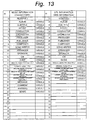
- Fig. 13 is a table that correlates key code values (0 to 63 of additional information and types thereof. Key code values (0 to 31) are assigned to music character information. Key code values (32 to 63) are assigned to URLs (Uniform Resource Locator) (web information). The music character information and URL information contain character information of the album title, the artist name, the CM, and so forth as additional information.
- Key code values (0 to 31) are assigned to music character information.
- Key code values (32 to 63) are assigned to URLs (Uniform Resource Locator) (web information).
- the music character information and URL information contain character information of the album title, the artist name, the CM, and so forth as additional information.
- Fig. 14 is a table that correlates key code values (64 to 127) of additional information and types thereof. Key code values (64 to 95) are assigned to paths/others. Key code values (96 to 127) are assigned to control/numeric data.
- ID 98 represents TOC-ID as additional information.
- TOC-ID represents the first music program number, the last music program number, the current program number, the total performance duration, and the current music program duration corresponding to the TOC information of a CD (Compact Disc).
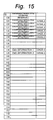
- Fig. 15 is a table that correlates key code values (128 to 159) of additional information and types thereof. Key code values (128 to 159) are assigned to synchronous reproduction information.
- EMD stands for electronic music distribution.
- Fig. 16A shows the data structure of the additional information.
- key code ID 3 (artist name as additional information).
- Variable length data after byte 12 represents one byte data "SIMON & GRAFUNKEL" as artist name. Since the data length of the additional information should be a multiple of 4 bytes, the rest is filled with (0x00).
- SIZE 0x14 (20 bytes) representing that the data length of the additional information is 20 bytes.
- the data is binary code.
- the variable length data is eight-byte ISRC code representing copyright information (nation, copyright owner, recorded year, and serial number).
- key code ID is 97 representing recorded date and time as additional information.
- SIZE 0 x 10 (16 bytes) representing that the data length of the additional information is 16 bytes.
- the variable length data is four-byte code (32 bit) representing the recorded date and time (year, month, day, hour, minute, second).
- variable length data is a four-byte code representing a reproduction log (year, month, day, hour, minute, second).
- Fig. 17 shows an attribute header (1 block) of a data file and a music data file (1 block).
- the first 32 bytes of the attribute header are used as a header; 256 bytes are used as a music program area NM1 (256 bytes); and 512 bytes are used as a music program title area NM2 (512 bytes).
- TRKINF Track information area
- This area is mainly used to totally manage the security information and copy control information.
- Fig. 19 shows a part of TRKINF.
- the secret sequence number is a sequence number recorded in the secret area of the memory card.
- a non-copyright protection type recorder cannot read data from the secret area of the memory card.
- a non-copyright protection type player may ignore information of bits 2 and 1.
- Bit 0 of the area A represents information of emphasis on/off state.
- Bit 1 of the area A represents information of reproduction skip or normal reproduction.
- Bit 2 of the area A represents information of data type such as audio data, FAX data, or the like.
- Bit 3 of the area A is undefined.
- mode information of ATRAC3 is defined as shown in Fig. 20.
- N is a mode value of 3 bits.
- the number of bytes of 1 SU in the monaural mode is 136 bytes.
- the number of bytes of 1 SU in the LP mode is 192 bytes.
- the number of bytes of 1 SU in the SP mode is 304 bytes.
- the number of bytes of 1 SU in the EX mode is 384 bytes.
- the number of bytes of 1 SU in the HQ mode is 512 bytes.
- Bit 7 of the area A represents ATRAC3 modes (0: Dual, 1: JOint).
- a 64 MB memory card has 3968 blocks.
- 1 SU is 304 bytes, one block has 53 SU.
- 1 SU is equivalent to (1024/44100) seconds.
- the track information area TRKINF is followed by a 24-byte part management information area (PRTINF) starting from 0x0370.
- PRTINF part management information area
- the attribute header of an ATRAC3 data file contains additional information INF.
- the additional information is the same as the additional information INF-S (see Figs. 11 and 12B) of the reproduction management file except that the start position is not fixed.
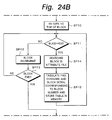
- step SP1 it is determined whether or not the value of the area ID BLKID at the beginning of the top block is BLKID-TL0.
- step SP2 the block number is incremented.
- step SP3 it is determined whether or not the last block has been searched.
- step SP3 When the determined result at step SP3 is No, the flow returns to step SP1.
- step SP4 it is determined that the searched block is the reproduction management file PBLIST. Thereafter, the flow advances to step SP5.
- the number of total tracks T-TRK in the reproduction management file PBLIST is stored as N to the register. For example, when the memory has stored 10 ATRAC3 data files (10 music programs), 10 has been stored in T-TRK.
- TRK-001 to TRK-400 of blocks are successively referenced.
- TRK-001 to TRK-010 of blocks are referenced.
- a table that correlates the track number TRK-XXX and the file number FNO is stored to the memory.
- N stored in the register is decremented. A loop of steps SP6, SP7, and SP8 is repeated until N becomes 0 at step SP9.
- step SP10 the pointer is reset to the top block.
- the searching process is repeated from the top block. Thereafter, the flow advances to step SP11.
- step SP11 it is determined whether or not the value of the area ID BLKID of the top block is BLKID-HD0.
- step SP12 the block number is incremented.
- step SP13 it is determined whether or not the last block has been searched.
- step SP13 When the determined result at step SP13 is No, the flow returns to step SP11. The searching process is repeated until the determined result at step SP11 becomes Yes.
- step SP14 it is determined that the block is the attribute header (see Fig. 8) (0x0000 to 0x03FFF shown in Fig. 18) at the beginning of the ATRAC3 data file.
- step SP15 with reference to the file number FNO, the sequence number BLOCK SERIAL of the same ATRAC data file, and the contents cumulation number key CONNUM0 contained in the attribute header, they are stored to the memory.
- the searching process is continued until 10 blocks are searched.
- step SP13 When the determined result at step SP13 is Yes, the flow advances to step SP16.
- step SP16 the pointer is reset to the top block. The searching process is repeated from the top block.
- step SP17 it is determined whether or not the value of the area ID BLKID of the top block is BLKID-A3D.
- step SP17 When the determined result at step SP17 is No, the flow advances to step SP18. At step SP18, the block number is incremented. Thereafter, at step SP18', it is determined whether or not the last block has been searched. When the determined result at step SP18' is No, the flow returns to step SP17.
- step SP17 When the determined result at step SP17 is Yes, the flow advances to step SP19. At step SP19, it is determined that the block contains ATRAC3 data. Thereafter, the flow advances to step SP20. At step SP20, with reference to the serial number BLOCK SERIAL recorded in the ATRAC3 data block and the contents cumulation number key CONNUM0, they are stored to the memory.
- the common number is assigned as the contents cumulation number key CONNUM0.
- a common number is assigned to all the values of the areas CONNUM0.
- serial numbers 1 to 0 are assigned to the values of the areas BLOCK SERIALs of the 10 blocks.
- the reproduction order of music programs of 100 data blocks and the connection order thereof can be obtained.
- step SP19 When the determined result at step SP19 is Yes, all the blocks have been searched for the reproduction management file, the ATRAC3 data file, and the attribute file. Thus, at step SP21, based on the values of the areas CONNUM0, BLOCK SERIAL, FNO, and TRK-X in the order of block numbers of the blocks stored in the memory, the file connection state is obtained.
- the FAT may be generated in a free area of the memory.
- Fig. 25 shows the file structure according to the second embodiment of the present invention.
- a music directory contains a track information management file TRKLIST.MSF (hereinafter, referred to as TRKLIST), a backup track information management file TRKLISTB.MSF (hereinafter, referred to as TRKLISTB), an additional information file INFLIST.MSF (that contains an artist name, an ISRC code, a time stamp, a still picture data, and so forth (this file is referred to as INFIST)), an ATRAC3 data file A3Dnnnn.MSF (hereinafter, referred to as A3nnn).
- the file TRKLIST contains two areas NAME1 and NAME2.
- the area NAME1 is an area that contains the memory card name and the program name (for one byte code corresponding to ASCII/8859-1 character code).
- the area NAME2 is an area that contains the memory card name and the program name (for two byte code corresponding to MS-JIS/Hankul/Chinese code).
- Fig. 26 shows the relation between the track information management file TRKLIST, the areas NAME1 and NAME2, and the ATRAC3 data file A3Dnnnn.
- the areas NAME1 and NAME2 for program names may be provided as a different file as the track information management file, in a system having a small storage capacity, it is convenient to totally manage the track information management file and program name files.
- the track information area TRKINF-nnnn and part information area PRTINF-nnnn of the track information management file TRKLIST are used to manage the data file A3Dnnnn and the additional information INFLIST. Only the ATRAC3 data file A3Dnnnn is encrypted.
- the data length in the horizontal direction is 16 bytes (0 to F).
- a hexadecimal number in the vertical direction represents the value at the beginning of the current line.
- the second embodiment three files that are the track management file TRKLIST (including a program title file), the additional information management file INFLIST, and the data file A3Dnnnn are used.
- the first embodiment see Figs. 7, 8, and 9
- Fig. 27 shows the detailed structure of the track information management file TRKLIST.
- the track information management file TRKLIST one cluster (block) is composed of 16 kbytes.
- the size and data of the file TRKLISTB are the same as those of the backup file TRKLISTB.
- the first 32 bytes of the track information management file are used as a header.
- the header of the file TRKLIST contains a BLKID-TL0/TL1 (backup file ID) area (4 bytes), an area T-TRK (2 bytes) for the number of total tracks, a maker code area MCode (2 bytes), an area REVISION (4 bytes) for the number of TRKLIST rewrite times, and an area S-YMDhms (4 bytes) (option) for update date and time data.
- BLKID-TL0/TL1 backup file ID
- T-TRK for the number of total tracks
- MCode 2 bytes
- REVISION 4 bytes
- S-YMDhms 4 bytes
- the last 16 bytes of the file TRKLIST are used for an area BLKID-TL0, an area MCode, and an area REVISION that are the same as those of the header.
- the backup file TRKLISTB contains the above-described header.
- the header contains an area BLKID-TL1, an area MCode, and an area REVISION.
- Fig. 27 shows the areas preceded by the area TRKLIST.
- the lower portion of the area TRKLISTB shows the detailed structure of these areas.
- a hatched area represents an unused area.
- the track information area TRKINF-nnn and the part information area PRTINF-nnn contain areas of an ATRAC3 data file.
- the track information area TRKINF-nnn and the part information area PRTINF-nnn each contain a reproduction restriction flag area LT (1 byte), a contents key area CONTENTS KEY (8 bytes), a recorder/player security block serial number area MG(D) SERIAL (16 bytes), an area XT (2 bytes) (option) for representing a feature portion of a music program, an area INX (2 bytes) (option), an area YMDhms-S (4 bytes) (option), an area YMDhms-E (4 bytes) (option), an area MT (1 byte) (option), an area CT (1 byte) (option), an area CC (1 byte) (option), an area CN (1 byte) (option) (these areas YMDhms-S, YMDhms-E, MT, CT, CC, and CN
- Fig. 28 shows the detailed structure of the area NAME1 (for one byte code area).
- PNM2-S represents the pointer to the name representing the memory card.
- Fig. 30 shows the data arrangement (for one block) of the ATRAC3 data file A3Dnnnn in the case that 1 SU is composed of N bytes. In this file, one slot is composed of eight bytes. Fig. 30 shows the values of the top portion (0x0000 to 0x3FF8) of each slot. The first four slots of the file are used for a header. As with the data block preceded by the attribute header of the data file (see Fig. 17) of the first example, a header is placed.
- the header contains an area BLKID-A3D (4 bytes), a maker code area MCode (2 bytes), an area BLOCK SEED (8 bytes) necessary for encrypting process, an area CONNUM0 (4 bytes) for the initial contents cumulation number, a serial number area BLOCK SERIAL (4 bytes) for each track, and an area INITIALIZATION VECTOR (8 bytes) necessary for encrypting/decrypting process.
- the second last slot of the block redundantly contains an area BLOCK SEED.
- the last slot contains areas BLKID-A3D and MCode.
- the header is followed by the sound unit data SU-nnnn.
- Fig. 31 shows the detailed data structure of the additional information management file INFLIST that contains additional information.
- the data size is represented with low order 16 bits (0001 to 7FFF).
- the data size represents the total data amount of the music program.
- the first INF represents a pointer to additional information of the entire album (normally, INF-409).
- Fig. 32 shows the structure of additional information.
- An 8-byte header is placed at the beginning of one additional information data area.
- the structure of the additional information is the same as that of the first embodiment (see Fig. 12C).
- the additional information contains an area IN (2 bytes) as an ID, an area key code ID (1 byte), an area SIZE (2 bytes) that represents the size of each additional information area, and a maker code area MCode (2 bytes).
- the additional information contains an area SID (1 byte) as a sub ID.
- the track information management file TRKLIST or music data is used.
- Fig. 33 shows a flow of a file recovering process.
- a computer that operates with a file recovery program and that can access the memory card and a storing device (hard disk, RAM, or the like) connected to the computer are used.
- the computer has a function equivalent to the DSP30.
- All blocks of the flash memory whose FAT has been destroyed are searched for TL-0 as the value (BLKID) at the top position of each block.
- all the blocks are searched for NM-1 as the value (BLKID) at the top position of each block.
- all the blocks are searched for NM-2 as the value (BLKID) at the top position of each block.
- All the contents of the four blocks are stored to for example a hard disk by the recovery computer.
- the number of total tracks is obtained from data after the fourth byte of the track information management file.
- the 20-th byte of the track information area TRKINF-001, the value of the area CONNUM-001 of the first music program, and the value of the next area P-001 are obtained.
- the number of parts is obtained with the value of the area P-001.
- the values of the areas PRTSIZE of all parts of the track 1 of the area PRTINF is obtained.
- the number of total blocks (clusters) n is calculated and obtained.
- step 102 a voice data file (ATRAC3 data file) is searched. All blocks of other than the management file is searched from the flash memory. Blocks whose top value (BLKID) is A3D are collected.
- BLKID top value
- a block of which the value of the area CONNUM0 at the 16-th byte of A3Dnnn is the same as that of the area CONNUM-001 of the first music program of the track information management file and of which the value of the area BLOCK SERIAL that starts from 20-th byte is 0 is searched.
- the ATRC3 data file is searched until n blocks (clusters) of the track 1 are obtained.
- n blocks (clusters) of the track 1 are obtained.
- the same process for the track 1 is performed for the track 2.
- a block of which the value of the area CONNUM0 is the same as that of the area CONNUM-002 of the first music program of the track information management file and of which the value of the area BLOCK SERIAL that starts at the 20-th byte is searched.
- the ATRAC3 data file is searched until the last block (cluster) n' is detected. After all blocks (clusters) are obtained, they are successively stored to the hard disk.
- all the ATRAC3 data is stored to the hard disk controlled by the recovering computer.
- step 103 the memory card whose the FAT has been destroyed is re-initialized and then the FAT is reconstructed.
- a predetermined directory is formed in the memory card.
- the track information management file and the ATRAC3 data file for m tracks are copied from the hard disk to the memory card. Thus, the recovery process is finished.
- important parameters in particular, codes in headers
- codes in headers may be recorded triply rather than doubly.
- data when data is redundantly recorded, the same data may be recorded at any positions as long as they are apart from each other for one page or more.
- reproduction management file PBLIST.MSF and TRAC3 data file that is compressed audio data. Since the reproduction management file PBLIST.MSF contains clock information S-YMDhms, the clock information is checked so as to prevent the user from forging it.
- a forge-check code is generated by calculating CONTENTS KEY (CK) of an ATRAC3 data file generated along with the reproduction management file PBLIST.MSF using the hash function.
- CONTENTS KEY (CK) is stored in another file.
- clock information S-YMDhms has not been entered, all hash values are set to zero with no calculations. Whenever the clock information S-YMDhms is updated, the hash values are calculated.
- an ATRAC3 data file that is audio data, track attribute A, reproduction limitation flag, security version LT, MG (D) serial number MG (D) Serial, contents cumulation number CONNUM, reproduction start date/time YMDhms-S, reproduction expiration date/time YMDhms-E, number of track reproduction times CT, number of reproduction permission times MT, copy control CC, and number of high speed digital copy permission times CN (optional) are forge-checked so as to prevent the user from forging them.
- a forge-check code is generated by calculating CONTENTS KEY (CK) of the ATRAC3 data file using the hash function. When the ATRAC3 data file is divided or combined, with new CONTENTS KEY, the hash value is re-calculated.
- Fig. 34 is a block diagram showing a forge-checking circuit of the digital audio recorder according to the present invention.
- a memory card is attached to the digital audio recorder or when the reproduction button is pressed, the attached memory is authenticated.
- a DSP (Digital Signal Processor) 30 causes the track information management file TRKLIST.MSF to be read from a flash memory of a memory card 40 to an S-RAM (Static RAM) 31.
- S-RAM Static RAM
- a reproduction limitation value block 70 is contained in the track information management file.
- the track information management file is stored in a predetermined area of the flash memory of the memory card 40.
- the reproduction limitation value block 70 is read from the flash memory to the SRAM 31 (36).
- the reproduction limitation value block 70 is forge-checked.
- the forge-checking circuit shown in Fig. 34 includes a hash calculating circuit 71, an encrypting circuit 22 having predetermined memory areas (72 and 73) that are non-volatile memories, a match detecting circuit 74, and a controlling portion 75.
- the controlling portion 75 has an inner clock 76.
- the hash calculating circuit 71, the match detecting circuit 74, and the controlling portion 75 are accomplished with a hardware structure or software processes.
- the software processes are performed by the DSP 30.
- the hash calculating circuit 71 can be accomplished with for example a functional device that composes the encrypting circuit 22.
- the controlling portion 75 monitors the attached state of the memory card 40. When the memory card 40 is attached to the digital audio player, the controlling portion 75 determines whether or not the reproducing operation of files stored in the memory card 40 is permitted corresponding to predetermined information of the reproduction limitation value block 70.
- the predetermined information is for example track attribute A, reproduction limitation flag, security version LT, MG (D) serial number MG (D) Serial, contents cumulation number CONNUM, reproduction start date/time YMDhms-S, reproduction expiration date/time YMDhms-E, number of track reproduction times CT, number of reproduction permission times MT, COPY Control CC, number of high speed digital copy permission times CN (optional), CONTENTS KEY (CK), and so forth.
- reproduction start date/time and reproduction expiration date/time are compared with the date/time of the inner clock 76 so as to determine whether or not the reproducing operation is permitted.
- the number of track reproduction times CT and the number of reproduction permission times MT, corresponding thereto it is determined whether or not the reproducing operation is permitted.
- the hash calculating circuit 71 calculates hash values of individual parameter of the reproduction limitation value block 70.
- the hash values are obtained using the hash function.
- the hash function is generally defined in ISO/IEC 10118-1, JIS X5057-1.
- the hash function is a function of which any two different input values that become the same output value cannot be calculated.
- a calculated result of the hash calculating circuit 71 is supplied to the encrypting circuit 22.
- Control information is supplied from the controlling portion 75 to the non-volatile memory of the encrypting circuit 22.
- Hash values calculated before the reproducing operation are stored in the predetermined memory area 72 as current hash values.
- hash values calculated after the former reproducing operation are stored as former hash values to the predetermined memory area 73.
- the current hash values and the former hash value stored in the encrypting circuit 22 are read and supplied to the match detecting circuit 74.
- the values in the predetermined memory areas (72 and 73) of the flash memory of the encrypting circuit 22 cannot be read from the outside of the digital audio recorder. Thus, it is impossible to access the hash values stored in the areas 72 and 73 from the outside. Only a match detection result of the match detecting circuit 74 can be read from the outside. An area that cannot be accessed from the outside is referred to as tamper resistant area.
- the match detecting circuit 74 compares the current hash values with the former hash values. Depending on whether the current hash values are the same as the former hash values, it is determined whether the reproduction limitation value block 70 has been forged. Output data of the match detecting circuit 74 is supplied to the controlling portion 75.
- the controlling portion 75 determines whether the reproducing operation is permitted or prohibited corresponding to both the determination based on track attribute A, reproduction limitation flag, security version LT, MG (D) serial number MG (D) Serial, contents cumulation number CONNUM, reproduction start date/time YMDhms-S, reproduction expiration date/time YMDhms-E, number of track reproduction times CT, number of reproduction permission times MT, COPY CONTROL CC, number of high speed digital copy permission times CN (optional), and CONTENTS KEY (CK) and the output data of the match detecting circuit 74.
- the controlling portion 75 generates control information corresponding to the determined result. In other words, when it is determined that the reproduction limitation value block 70 has not been forged and the reproducing operation is permitted, the controlling portion 75 generates control information that permits the reproducing operation.
- the controlling portion 75 when the reproduction limitation value block 70 has been forged, the controlling portion 75 generates control information that prohibits the reproducing operation. Even if the reproduction limitation value block 70 has not been forged, when the reproducing operation is prohibited corresponding to track attribute A, reproduction limitation flag, security version LT, MG (D) serial number MG (D) Serial, contents cumulation number CONNUM, reproduction start date/time YMDhms-S, reproduction expiration date/time YMDhms-E, number of track reproduction times CT, number of reproduction permission times MT, COPY CONTROL CC, number of high speed digital copy permission times CN (optional), and CONTENTS KEY (CK), the reproducing operation is prohibited.
- the forge-checking process for an ATRAC3 data file was explained. Likewise, the forge-checking process is performed for the clock information S-YMDhms contained in the reproduction management file PBLIST.MSF.
- a forge-check code is generated by calculating CONTENTS KEY (CK) of the first program of an ATRAC3 data file generated along with the reproduction management file PBLIST.MSF using the hash function.
- the calculating process of this example is performed in the same manner as that for an ATRAC3 data file.
- the circuit of this calculating process can be shared with that for the ATRAC3 data file. Since the file may be erased or moved, the value of CONTENTS KEY (CK) is stored in another file.
- CK CONTENTS KEY
- Fig. 35 shows a process of which an EMD (Electric Music Distribution) terminal (not shown) downloads an ATRAC3 data file in the format according to the first embodiment to a memory card.
- Fig. 35 shows a process of which the EMD terminal downloads an ATRAC3 data file that has been compressed and encrypted through a public line (ISDN line, telephone line, or satellite line) to a memory card.
- a public line ISDN line, telephone line, or satellite line
- a reproduction management file PBLIST.MSF is generated.
- the downloaded date/time information is generated.
- the downloaded date/time information is recorded as clock information S-YMDhms of the reproduction management file PBLIST.MSF.
- step SP102 when an ATRAC3 data file that has been compressed and encrypted is received through the public line (ISDN line, telephone line, or satellite line) and recorded to the flash memory, an attribute header is generated as shown in Fig. 9 and added to the ATRAC3 data file.
- the public line ISDN line, telephone line, or satellite line
- the hash calculating circuit 71 calculates the clock information S-YMDhms of the reproduction management file PBLIST.MSF using the hash function and stores the calculated value to the memory area 73 of the encrypting circuit 22.
- the hash calculating circuit 71 calculates the reproduction limitation information (track attribute A, reproduction limitation flag, security version LT, reproduction start date/time YMDhms-S, reproduction expiration date/time YMDhms-E, number of track reproduction times CT, number of reproduction permission times MT, COPY CONTROL CC, and number of high speed digital copy permission times CN (optional) of the ATRACK3 data file using the hash function.
- the calculated value obtained by the hash calculating circuit 71 is stored in the memory area 73 of the encrypting circuit 22.
- the hash calculating circuit 71 calculates the MG (D) serial number MG (D) Serial and the contents cumulation number CONNUM generated along with the attribute file using the hash function.
- the calculated value obtained by the hash calculating circuit 71 is stored in the memory area 73 of the encrypting circuit 22. Since data is recorded to a virgin flash memory, no data has been recorded in the memory area 72 of the encrypting circuit 22.
- step SP105 it is determined whether or not the flash memory has been detached from the EMD terminal.
- the flow advances to step SP106.
- step SP106 it is determined whether or not the flash memory has been re-attached.
- step SP107 it is determined whether or not the power of the EMD terminal has been turned off.
- step SP107 When the determined result at step SP107 is Yes, the flow advances to step SP108. At step SP108, it is determined whether or not the power has been turned on again.
- step SP109 When the determined result at step SP106 is Yes or when the determined result at step SP108 is Yes, the flow advances to step SP109.
- step SP109 with CONTENTS KEY (CK) contained in the attribute header, the hash calculating circuit 71 calculates the clock information S-YMDhms of the reproduction management file PBLIST.MSF using the hash function. The calculated value obtained by the hash calculating circuit 71 is stored to the memory area 72 of the encrypting circuit 22.
- step SP110 it is determined whether or not the current hash values stored in the memory area 72 of the encrypting circuit 22 matches the former hash values stored in the memory area 73 of the encrypting circuit 22.
- the determined result at step SP110 is Yes, the current hash values stored in the memory area 72 of the encrypting circuit 22 are copied to the former hash values stored in the memory area 73 of the encrypting circuit 22.
- step SP111 it is determined whether or not a reproduction command has been issued.
- the flow advances to step SP112.
- the hash calculating circuit 71 calculates the track attribute A, reproduction limitation flag, security version LT, MG (D) serial number MG (D) Serial, contents cumulation number CONNUM, reproduction start date/time YMDhms-S, reproduction expiration date/time YMDhms-E, number of track reproduction times CT, number of reproduction permission times MT, COPY CONTROL CC, and number of high speed digital copy permission times CN (optional) of the attribute file added to the ATRAC3 data file corresponding to the reproduction command using the hash function.
- the calculated value obtained by the hash calculating circuit 71 is stored in the memory area 72 of the encrypting circuit 22.
- step SP113 it is determined whether or not the hash values stored in the memory area 72 of the encrypting circuit 22 obtained by the hash calculating circuit 71 match the hash values stored in the memory area 73 of the encrypting circuit 22.
- the match detecting circuit 74 compares the currently calculated hash values with the formerly calculated hash values. When they match, it is determined that any information of track attribute A, reproduction limitation flag, security version LT, MG (D) serial number MG (D) Serial, contents cumulation number CONNUM, reproduction start date/time YMDhms-S, reproduction expiration date/time YMDhms-E, number of track reproduction times CT, number of reproduction permission times MT, COPY CONTROL CC, and number of high speed digital copy permission times CN (optional) of the attribute file has not been forged. Thereafter, the flow advances to step SP114. At step SP114, the reproducing operation of the ATRAC3 data file is permitted.
- step SP113 When the determined result at step SP113 is No, it is determined that some of the track attribute A, reproduction limitation flag, security version LT, MG (D) serial number MG (D) Serial, contents cumulation number CONNUM, reproduction start date/time YMDhms-S, reproduction expiration date/time YMDhms-E, number of track reproduction times CT, number of reproduction permission times MT, COPY CONTROL CC, and number of high speed digital copy permission times CN (optional) of the attribute file has been forged.
- step SP115 At step SP115, the reproducing operation of the ATRAC3 data file is prohibited. Thereafter, the flow advances to step SP116.
- step SP116 a forging flag is set.
- the ATRAC3 data file When the ATRAC3 data file is reproduced, it is determined whether or not predetermine values (any positive integers) have been set to the number of track reproduction times CT and the number of reproduction permission times MT. When a predetermined value has been set to the number of track reproduction times CT, it is decremented by 1. When the number of track reproduction times CT is zero and a predetermined number (any positive integer) has been set to the number of reproduction permission times MT, since the reproducing operation has been performed the number of reproduction permission times, the reproducing operation of the ATRAC3 data file is prohibited.
- predetermine values any positive integers
- Fig. 36 shows an example of a process of which the EMD (Electric Music distribution) terminal downloads a music file having a two-times reproduction limitation. For simplicity, it is assumed that the reproduction expiration date/time is not limited.
- the EMD terminal has the same encrypting circuit (not shown) as the above-described digital audio recorder.
- the encrypting circuit authenticates an attached memory card. When the attached memory card has been successfully authenticated, the encrypting circuit records an encrypted audio file (ATRAC3 data file) to the memory card.
- the EMD terminal supplies reproduction limitation information of the audio file to the digital audio recorder.
- the digital audio recorder performs a formatting process for the audio file and the reproduction limitation information and records the formatted data to the flash memory.
- the EMD terminal downloads data to the digital audio recorder, it performs a process denoted by S201.
- the hash calculating circuit 71 calculates hash values of several parameters (reproduction limitation value block 70) including MT, CT, and CONTENTS ID.
- the hash values calculated by the hash calculating circuit 71 is stored to the memory area 73 of the encrypting circuit 22. Thereafter, when the power of the digital audio recorder is turned off or when the memory card 40 is detached, the reproduction limitation value block 70 is checked for forged information. If necessary, whenever the reproducing operation is performed, the reproduction limitation value block 70 can be checked for forged information.
- the hash calculating circuit 71 calculates hash values of the reproduction limitation value block 70.
- the hash values calculated by the hash calculating circuit 71 are stored as current hash values to the memory area 72 of the encrypting circuit 22.
- the current hash values and the former hash values are read and supplied to the match detecting circuit 74.
- the match detecting circuit 74 compares the current hash values with the former hash values. Depending on whether they match, the match detecting circuit 74 determines whether or not the reproduction limitation value block 70 has been forged.
- the match detecting circuit 74 supplies the detected result to the controlling portion 75.
- the controlling portion 75 forms control information.
- the reproduction limitation value block 70 has not been forged, since the current hash values are the same as the former hash values, forged information is not detected.
- CT since the number of reproduction times CT is not zero (CT ⁇ 0), the flow advances to step S5.
- the controlling portion 75 forms control information for controlling the reproducing operation and starts the reproducing operation.
- the flow advances to step S6.
- hash values of the reproduction limitation value block 70 are calculated and stored as the former hash values to the memory area 73.
- step S203 the same process as step S202 is performed.
- hash values of the reproduction limitation value block 70 are calculated and compared with the former hash values.
- it is determined whether or not the reproduction limitation value block 70 has been forged (at step S8).
- the reproducing operation is performed (at step S9).
- the reproducing operation is prohibited.
- the memory card 40 is detached and then attached again, when the reproduction command is issued at step S11, the flow advances to step S12.
- the controlling portion 75 forms control information that prohibits the reproducing operation (at step S13).
- the user is informed that because the number of reproduction times CT matches the number of reproduction permission times MT, the reproducing operation is prohibited.
- TRKINF of the track information management file TRKLIST has been forged.
- step S23 hash values of the reproduction limitation value block 70 are calculated.
- the hash values are stored as the current hash values to the memory area 72.
- the match detecting circuit 74 determines whether the current hash values match the former hash values. In this case, since the reproduction limitation value block 70 has been forged, the match detecting circuit 74 determines that they do not match. Thus, the controlling portion 75 forms control information that prohibits the reproducing operation (at step S23).
- step S24 the reproducing operation is not performed. In this case, with the speaker and display, the user is informed that because the reproduction limitation value block 70 has been forged, the reproducing operation is prohibited.
- step S25 the forging flag is set to a predetermined position (for example, the area "Reserved" shown in Fig. 27) of TRKINF of TRKLIST.
- the hash values are calculated and stored.
- the reproducing operation is prohibited (at step S26).
- the forging flag is checked.
- the controlling portion 75 determines that reproducing operation is prohibited.
- the controlling portion 75 forms control information that prohibits the reproducing operation.
- the reproducing operation is not performed.
- the number of reproduction times CT is decremented by 1.
- the reproducing operation is prohibited.
- the number of reproduction times CT may be incremented by 1.
- the reproducing operation may be prohibited.
- the number of reproduction permission times MT may be decremented by 1 without the number of reproduction times CT.
- the reproduction expiration date/time is written to the track information management file of the memory card.
- Hash values of the reproduction limitation value block 70 including the reproduction expiration date/time are calculated.
- the hash values are stored as former hash values to the memory area 73 of the encrypting circuit 22.
- the reproduction limitation value block 70 is checked for forged information.
- the date/time of the inner clock 76 of the controlling portion 75 is matched with the reproduction expiration date/time.
- the match detecting circuit 74 compares the hash values currently calculated with the hash values formerly calculated. Depending on whether they match, the match detecting circuit 74 determines whether the reproduction limitation value block 70 has been forged. In addition, the match detecting circuit 74 compares the date/time of the inner clock 76 with the reproduction expiration date/time. When the reproduction limitation value block 70 has not been forged and the date/time of the inner clock 76 is before the reproduction expiration date/time as the determined results of the match detecting circuit 74, the reproducing operation is performed.
- the reproducing operation is prohibited.
- the date/time of the inner clock 76 exceeds the reproduction expiration date/time as the determined results of the match detecting circuit 74, even if the reproduction limitation value block 70 has not been forged, an expiration flag is set to a predetermined position (for example, the area "Reserved" shown in Fig. 27) of TRKINF of TRKLIST.
- the reproduction expiration date/time is determined with priority against whether or not the reproduction limitation value block has been forged. Thus, the reproducing operation is prohibited.
- the current hash values and the former hash values are compared. When they do not match, since it is determined that the reproduction limitation value block 70 has been forged, the reproducing operation is prohibited. However, even if the current hash values match the former hash values, unless the reproduction expiration date/time is proper, the reproducing operation is prohibited. When the reproducing operation is prohibited, with the speaker or display, the user is informed of a relevant message. Even if the date/time of the inner clock 76 exceeds the reproduction expiration date/time, hash values of the reproduction limitation value block 70 are calculated and stored against future forged information.
- the reproduction start date/time is written to the track information management file.
- Hash values of the reproduction limitation value block 70 including the reproduction expiration date/time are calculated and supplied to the encrypting circuit 22.
- the hash values are supplied to the encrypting circuit 22.
- the hash values are stored as former hash values to the memory area 73 of the encrypting circuit 22.
- the current hash values and the former hash values are compared.
- the date/time of the inner clock 76 and the reproduction start date/time are compared.
- the reproducing operation is prohibited.
- the reproduction limitation value block 70 has not been forged, when the date/time of the inner clock 76 does not exceed the reproduction start date/time as the determined results, the reproduction start date/time is determined with priority against forged information. Thus, the reproducing operation is prohibited.
- hash values of individual parameters (CONTENTS ID, number of reproduction times CT, number of reproduction permission times MT, reproduction expiration date/time, and reproduction start date/time) of the reproduction limitation value block are calculated.
- these hash values may be calculated for each music file.
- the present invention was applied to a digital audio recorder.
- the present invention can be applied to other apparatuses that deal with other types of data such as video data, audio data, program data, and so forth.
- hash values of reproduction limitation information are calculated.
- the obtained hash values are stored in a memory area that cannot be accessed from the outside of the apparatus.
- the controlling portion detects forged information corresponding to the output data of the comparing means, the controlling portion prohibits the reproducing operation.
- forged information can be securely detected.
- the reproducing operation of the file having the forged information can be prohibited.
Applications Claiming Priority (12)
| Application Number | Priority Date | Filing Date | Title |
|---|---|---|---|
| JP5586099 | 1999-03-03 | ||
| JP5586099 | 1999-03-03 | ||
| JP8491899 | 1999-03-26 | ||
| JP8491899 | 1999-03-26 | ||
| JP17818899 | 1999-06-24 | ||
| JP17818899 | 1999-06-24 | ||
| JP18341199 | 1999-06-29 | ||
| JP18341199 | 1999-06-29 | ||
| JP34747499 | 1999-12-07 | ||
| JP34747499 | 1999-12-07 | ||
| JP2000023329 | 2000-01-27 | ||
| JP2000023329A JP4779183B2 (ja) | 1999-03-26 | 2000-01-27 | 再生装置および再生方法 |
Publications (3)
| Publication Number | Publication Date |
|---|---|
| EP1041573A2 true EP1041573A2 (fr) | 2000-10-04 |
| EP1041573A3 EP1041573A3 (fr) | 2001-01-10 |
| EP1041573B1 EP1041573B1 (fr) | 2010-01-06 |
Family
ID=27550617
Family Applications (1)
| Application Number | Title | Priority Date | Filing Date |
|---|---|---|---|
| EP00301733A Expired - Lifetime EP1041573B1 (fr) | 1999-03-03 | 2000-03-03 | Appareil de lecture et méthode de lecture |
Country Status (2)
| Country | Link |
|---|---|
| EP (1) | EP1041573B1 (fr) |
| DE (1) | DE60043633D1 (fr) |
Cited By (7)
| Publication number | Priority date | Publication date | Assignee | Title |
|---|---|---|---|---|
| EP1058255A2 (fr) * | 1999-05-31 | 2000-12-06 | Sony Corporation | Appareil de traitement d'information, méthode de traitement d'information, et support d'enrégistrement de programme |
| WO2003075273A2 (fr) * | 2002-03-07 | 2003-09-12 | Matsushita Electric Industrial Co., Ltd. | Support d'enregistrement d'informations, procede et appareil de gestion de l'utilisation |
| EP1376595A2 (fr) * | 2002-06-11 | 2004-01-02 | Pioneer Corporation | Support d'enregistrement, et appareil d'enregistrement, appareil de lecture, leur méthode d'enregistrement et leur méthode de contrôle |
| WO2004079490A2 (fr) * | 2003-03-04 | 2004-09-16 | Koninklijke Philips Electronics N.V. | Confirmation de copie autorisee |
| CN100372017C (zh) * | 2000-12-07 | 2008-02-27 | 索尼公司 | 再现装置和再现方法 |
| US8205094B2 (en) | 2002-05-28 | 2012-06-19 | Nokia Corporation | Tamper evident removable media storing executable code |
| TWI406269B (zh) * | 2005-01-24 | 2013-08-21 | Thomson Licensing | 安全媒體上經編密碼的內容利用播放機之解密方法及播放機所用之媒體 |
Citations (4)
| Publication number | Priority date | Publication date | Assignee | Title |
|---|---|---|---|---|
| US5497419A (en) * | 1994-04-19 | 1996-03-05 | Prima Facie, Inc. | Method and apparatus for recording sensor data |
| US5530235A (en) * | 1995-02-16 | 1996-06-25 | Xerox Corporation | Interactive contents revealing storage device |
| WO1997025798A1 (fr) * | 1996-01-11 | 1997-07-17 | Mrj, Inc. | Systeme permettant d'agir sur l'acces a la propriete numerique et sur sa diffusion |
| EP0802535A1 (fr) * | 1995-10-09 | 1997-10-22 | Matsushita Electric Industrial Co., Ltd. | Support, appareil et procede d'enregistrement d'informations |
-
2000
- 2000-03-03 DE DE60043633T patent/DE60043633D1/de not_active Expired - Lifetime
- 2000-03-03 EP EP00301733A patent/EP1041573B1/fr not_active Expired - Lifetime
Patent Citations (4)
| Publication number | Priority date | Publication date | Assignee | Title |
|---|---|---|---|---|
| US5497419A (en) * | 1994-04-19 | 1996-03-05 | Prima Facie, Inc. | Method and apparatus for recording sensor data |
| US5530235A (en) * | 1995-02-16 | 1996-06-25 | Xerox Corporation | Interactive contents revealing storage device |
| EP0802535A1 (fr) * | 1995-10-09 | 1997-10-22 | Matsushita Electric Industrial Co., Ltd. | Support, appareil et procede d'enregistrement d'informations |
| WO1997025798A1 (fr) * | 1996-01-11 | 1997-07-17 | Mrj, Inc. | Systeme permettant d'agir sur l'acces a la propriete numerique et sur sa diffusion |
Cited By (14)
| Publication number | Priority date | Publication date | Assignee | Title |
|---|---|---|---|---|
| US7143445B1 (en) | 1999-05-31 | 2006-11-28 | Sony Corporation | Information processing apparatus, information processing method, and program storage medium |
| EP1058255A3 (fr) * | 1999-05-31 | 2004-03-31 | Sony Corporation | Appareil de traitement d'information, méthode de traitement d'information, et support d'enrégistrement de programme |
| EP1058255A2 (fr) * | 1999-05-31 | 2000-12-06 | Sony Corporation | Appareil de traitement d'information, méthode de traitement d'information, et support d'enrégistrement de programme |
| CN100372017C (zh) * | 2000-12-07 | 2008-02-27 | 索尼公司 | 再现装置和再现方法 |
| US8031869B2 (en) | 2002-03-07 | 2011-10-04 | Panasonic Corporation | Information recording medium, usage management method, and usage management apparatus |
| WO2003075273A2 (fr) * | 2002-03-07 | 2003-09-12 | Matsushita Electric Industrial Co., Ltd. | Support d'enregistrement d'informations, procede et appareil de gestion de l'utilisation |
| WO2003075273A3 (fr) * | 2002-03-07 | 2004-10-07 | Matsushita Electric Ind Co Ltd | Support d'enregistrement d'informations, procede et appareil de gestion de l'utilisation |
| US8205094B2 (en) | 2002-05-28 | 2012-06-19 | Nokia Corporation | Tamper evident removable media storing executable code |
| US7028908B2 (en) | 2002-06-11 | 2006-04-18 | Pioneer Corporation | Recording medium, and recording apparatus, reproducing apparatus, recording method and control method thereof |
| EP1376595A3 (fr) * | 2002-06-11 | 2004-10-06 | Pioneer Corporation | Support d'enregistrement, et appareil d'enregistrement, appareil de lecture, leur méthode d'enregistrement et leur méthode de contrôle |
| EP1376595A2 (fr) * | 2002-06-11 | 2004-01-02 | Pioneer Corporation | Support d'enregistrement, et appareil d'enregistrement, appareil de lecture, leur méthode d'enregistrement et leur méthode de contrôle |
| WO2004079490A3 (fr) * | 2003-03-04 | 2004-11-11 | Koninkl Philips Electronics Nv | Confirmation de copie autorisee |
| WO2004079490A2 (fr) * | 2003-03-04 | 2004-09-16 | Koninklijke Philips Electronics N.V. | Confirmation de copie autorisee |
| TWI406269B (zh) * | 2005-01-24 | 2013-08-21 | Thomson Licensing | 安全媒體上經編密碼的內容利用播放機之解密方法及播放機所用之媒體 |
Also Published As
| Publication number | Publication date |
|---|---|
| EP1041573B1 (fr) | 2010-01-06 |
| EP1041573A3 (fr) | 2001-01-10 |
| DE60043633D1 (de) | 2010-02-25 |
Similar Documents
| Publication | Publication Date | Title |
|---|---|---|
| AU758947B2 (en) | Reproducing apparatus and reproducing method | |
| EP1041572B1 (fr) | Mémoire non-volatile et appareil de lecture pour mémoire non-volatile | |
| US8607069B2 (en) | Data processing apparatus, data processing method, terminal unit, and transmission method of data processing apparatus | |
| US6691149B1 (en) | System for distributing music data files between a server and a client and returning the music data files back to the previous locations | |
| US7155013B2 (en) | Recording apparatus, recording method, reproducing apparatus, and reproducing method | |
| US8755671B2 (en) | Reproducing apparatus and reproducing method | |
| US6212097B1 (en) | Nonvolatile memory | |
| US6807024B1 (en) | Reproducing apparatus and reproducing method | |
| US6985584B1 (en) | Non-volatile record medium, recording method, and recording apparatus | |
| EP1079393A2 (fr) | Appareil d'édition, méthodes d'édition, et mémoires non-volatiles | |
| EP1041573B1 (fr) | Appareil de lecture et méthode de lecture | |
| EP1041576B1 (fr) | Média d'enregistrement non-volatile, média d'enregistrement, et méthode d'enregistrement | |
| GB2351819A (en) | Reproduction apparatus and method | |
| EP1033665A2 (fr) | Système de communication de données et méthode de gestion de données | |
| EP1041574B1 (fr) | Mémoire non-volatile | |
| EP1927989B1 (fr) | Appareil d'édition et procédé d'édition | |
| ZA200006274B (en) | Data processing apparatus, data processing method, terminal unit, and transmission method of data processing apparatus. | |
| MXPA00002863A (en) | Reproducing apparatus and reproducing method |
Legal Events
| Date | Code | Title | Description |
|---|---|---|---|
| PUAI | Public reference made under article 153(3) epc to a published international application that has entered the european phase |
Free format text: ORIGINAL CODE: 0009012 |
|
| AK | Designated contracting states |
Kind code of ref document: A2 Designated state(s): DE FR GB |
|
| AX | Request for extension of the european patent |
Free format text: AL;LT;LV;MK;RO;SI |
|
| PUAL | Search report despatched |
Free format text: ORIGINAL CODE: 0009013 |
|
| AK | Designated contracting states |
Kind code of ref document: A3 Designated state(s): AT BE CH CY DE DK ES FI FR GB GR IE IT LI LU MC NL PT SE |
|
| AX | Request for extension of the european patent |
Free format text: AL;LT;LV;MK;RO;SI |
|
| RIC1 | Information provided on ipc code assigned before grant |
Free format text: 7G 11C 7/16 A, 7G 06F 12/14 B |
|
| 17P | Request for examination filed |
Effective date: 20010615 |
|
| AKX | Designation fees paid |
Free format text: DE FR GB |
|
| 17Q | First examination report despatched |
Effective date: 20071031 |
|
| GRAP | Despatch of communication of intention to grant a patent |
Free format text: ORIGINAL CODE: EPIDOSNIGR1 |
|
| GRAC | Information related to communication of intention to grant a patent modified |
Free format text: ORIGINAL CODE: EPIDOSCIGR1 |
|
| GRAS | Grant fee paid |
Free format text: ORIGINAL CODE: EPIDOSNIGR3 |
|
| GRAA | (expected) grant |
Free format text: ORIGINAL CODE: 0009210 |
|
| AK | Designated contracting states |
Kind code of ref document: B1 Designated state(s): DE FR GB |
|
| REG | Reference to a national code |
Ref country code: GB Ref legal event code: FG4D |
|
| REF | Corresponds to: |
Ref document number: 60043633 Country of ref document: DE Date of ref document: 20100225 Kind code of ref document: P |
|
| PLBE | No opposition filed within time limit |
Free format text: ORIGINAL CODE: 0009261 |
|
| STAA | Information on the status of an ep patent application or granted ep patent |
Free format text: STATUS: NO OPPOSITION FILED WITHIN TIME LIMIT |
|
| 26N | No opposition filed |
Effective date: 20101007 |
|
| PGFP | Annual fee paid to national office [announced via postgrant information from national office to epo] |
Ref country code: DE Payment date: 20140328 Year of fee payment: 15 |
|
| PGFP | Annual fee paid to national office [announced via postgrant information from national office to epo] |
Ref country code: FR Payment date: 20140319 Year of fee payment: 15 |
|
| PGFP | Annual fee paid to national office [announced via postgrant information from national office to epo] |
Ref country code: GB Payment date: 20140319 Year of fee payment: 15 |
|
| REG | Reference to a national code |
Ref country code: DE Ref legal event code: R119 Ref document number: 60043633 Country of ref document: DE |
|
| GBPC | Gb: european patent ceased through non-payment of renewal fee |
Effective date: 20150303 |
|
| REG | Reference to a national code |
Ref country code: FR Ref legal event code: ST Effective date: 20151130 |
|
| PG25 | Lapsed in a contracting state [announced via postgrant information from national office to epo] |
Ref country code: GB Free format text: LAPSE BECAUSE OF NON-PAYMENT OF DUE FEES Effective date: 20150303 Ref country code: DE Free format text: LAPSE BECAUSE OF NON-PAYMENT OF DUE FEES Effective date: 20151001 |
|
| PG25 | Lapsed in a contracting state [announced via postgrant information from national office to epo] |
Ref country code: FR Free format text: LAPSE BECAUSE OF NON-PAYMENT OF DUE FEES Effective date: 20150331 |