EP1036491B1 - Cooling system for semiconductor die carrier - Google Patents
Cooling system for semiconductor die carrier Download PDFInfo
- Publication number
- EP1036491B1 EP1036491B1 EP98958566A EP98958566A EP1036491B1 EP 1036491 B1 EP1036491 B1 EP 1036491B1 EP 98958566 A EP98958566 A EP 98958566A EP 98958566 A EP98958566 A EP 98958566A EP 1036491 B1 EP1036491 B1 EP 1036491B1
- Authority
- EP
- European Patent Office
- Prior art keywords
- fins
- cooling
- cooling system
- heat exchanger
- semiconductor die
- Prior art date
- Legal status (The legal status is an assumption and is not a legal conclusion. Google has not performed a legal analysis and makes no representation as to the accuracy of the status listed.)
- Expired - Lifetime
Links
- 238000001816 cooling Methods 0.000 title claims description 85
- 239000004065 semiconductor Substances 0.000 title claims description 39
- 239000012080 ambient air Substances 0.000 claims description 11
- RYGMFSIKBFXOCR-UHFFFAOYSA-N Copper Chemical compound [Cu] RYGMFSIKBFXOCR-UHFFFAOYSA-N 0.000 claims description 2
- 229910052782 aluminium Inorganic materials 0.000 claims description 2
- XAGFODPZIPBFFR-UHFFFAOYSA-N aluminium Chemical compound [Al] XAGFODPZIPBFFR-UHFFFAOYSA-N 0.000 claims description 2
- 229910052802 copper Inorganic materials 0.000 claims description 2
- 239000010949 copper Substances 0.000 claims description 2
- 229910052751 metal Inorganic materials 0.000 claims description 2
- 239000002184 metal Substances 0.000 claims description 2
- 239000000956 alloy Substances 0.000 claims 1
- 229910045601 alloy Inorganic materials 0.000 claims 1
- 239000003570 air Substances 0.000 description 19
- 239000000969 carrier Substances 0.000 description 4
- 230000004048 modification Effects 0.000 description 2
- 238000012986 modification Methods 0.000 description 2
- 241001417523 Plesiopidae Species 0.000 description 1
- 239000004020 conductor Substances 0.000 description 1
- 230000017525 heat dissipation Effects 0.000 description 1
- 238000011144 upstream manufacturing Methods 0.000 description 1
Images
Classifications
-
- H—ELECTRICITY
- H01—ELECTRIC ELEMENTS
- H01L—SEMICONDUCTOR DEVICES NOT COVERED BY CLASS H10
- H01L23/00—Details of semiconductor or other solid state devices
- H01L23/34—Arrangements for cooling, heating, ventilating or temperature compensation ; Temperature sensing arrangements
- H01L23/46—Arrangements for cooling, heating, ventilating or temperature compensation ; Temperature sensing arrangements involving the transfer of heat by flowing fluids
- H01L23/467—Arrangements for cooling, heating, ventilating or temperature compensation ; Temperature sensing arrangements involving the transfer of heat by flowing fluids by flowing gases, e.g. air
-
- H—ELECTRICITY
- H05—ELECTRIC TECHNIQUES NOT OTHERWISE PROVIDED FOR
- H05K—PRINTED CIRCUITS; CASINGS OR CONSTRUCTIONAL DETAILS OF ELECTRIC APPARATUS; MANUFACTURE OF ASSEMBLAGES OF ELECTRICAL COMPONENTS
- H05K7/00—Constructional details common to different types of electric apparatus
- H05K7/20—Modifications to facilitate cooling, ventilating, or heating
-
- H—ELECTRICITY
- H01—ELECTRIC ELEMENTS
- H01L—SEMICONDUCTOR DEVICES NOT COVERED BY CLASS H10
- H01L2924/00—Indexing scheme for arrangements or methods for connecting or disconnecting semiconductor or solid-state bodies as covered by H01L24/00
- H01L2924/0001—Technical content checked by a classifier
- H01L2924/0002—Not covered by any one of groups H01L24/00, H01L24/00 and H01L2224/00
Definitions
- the present invention relates to a cooling system for a semiconductor die carrier.
- Conventional cooling systems for a semiconductor die carrier suffer from several disadvantages. While conventional cooling systems do provide some measure of cooling for semiconductor die carriers, they do not provide optimum cooling capability for the semiconductor die housed in the carrier and optimum performance cannot be achieved. Conventional cooling systems for a semiconductor die carriers rely on a fan mounted adjacent to the die carrier. This close spatial relationship and limitation on airflow passage size reduces the cooling system's ability to effectively remove the heat generated by the die. Furthermore, conventional cooling systems for a semiconductor die carriers rely on the use of warm air from within a computer enclosure to cool the semiconductor die package. Often, the air within the enclosure is substantially warmer than the ambient air outside the computer enclosure. The performance of a semiconductor becomes degraded as the temperature of the die carrier increases. Thus, the above-referenced disadvantages directly effect the performance of the semiconductor die.
- US-A-4674004 discloses a cooling system comprising a cooling fan 16, a cooling duct with inlet and outlet aperture 40 and an heat exchanger 42 (see Fig. 4) mounted on a carrier (PCB) 24, whereby the apertures are disposed upstream and adjacent to the face of the heat exchanger and the heat exchanger comprises fins. Cooling air exiting the aperture impinges onto the face of the hea exchanger in a direction perpendicular thereto an is then carried in opposite directions across the heat exchanger.
- US-A-4715438 shows a heat exchanger 1 which comprises radially oriented on a spreader plate 2 first fins 5f3 (see Fig. 1) of a first length interspersed between second fins 5f1 of a second length.
- Fig. 2A shows that incomming air strikes the spreader plate 2 in a direction perpendicular thereto and is then dispersed outwardly passing between the fins in a direction parallel thereto.
- the present invention is directed to a cooling system for a semiconductor die carrier as defined in claim 1.
- the cooling system preferably relies upon cool ambient air from the exterior of a computer enclosure to cool the semiconductor die.
- the cooling system further preferably directs the cool ambient air from the exterior of a computer into a heat exchange relationship with the semiconductor die carrier.
- the cooling system for a semiconductor die carrier includes a cooling fan disposed at a substantial distance from a semiconductor die carrier, a cooling duct including an inlet portion and an outlet portion, the cooling duct inlet portion attached to the cooling fan, an a heat exchanger disposed on an upper surface of the semiconductor die carrier, wherein the cooling duct outlet portion is disposed in close proximity to the heat exchanger such that the cooling fan draws ambient air into the cooling duct and the ambient air exits the cooling duct outlet portion and passes in a heat exchange relationship with the heat exchanger.
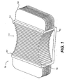
- FIG. 1 shows an isometric view of a preferred embodiment of a heat exchanger 50 in accordance with the present invention.
- a heat exchanger according to the present invention includes a contact portion and heat dissipating extensions, wherein the contact portion is adapted to contact an upper surface of a semiconductor die carrier.
- heat exchanger 50 includes contact portion 52 and first and second groups of fins 54 and 58 respectively.
- Contact portion 52 is adapted to be mounted to the top surface of a semiconductor die carrier.
- a heat exchanger further includes a first and a second group of fins, the first group of fins oriented perpendicularly with respect to the second group of fins.
- first group of fins 54 are mounted vertically, while second group of fins 58 are mounted horizontally.
- first group of fins 54 are separated from one another by an air gap so that cooling air may flow freely (along direction A ) between the fins.
- Second group of fins 58 are similarly separated from one another by an air gap so that cooling air may flow freely (along direction A ) between the fins.
- each of the first group of fins includes first and second ends, the first ends of the first group of fins being disposed in a curvilinear array.
- first group of fins 54 include first ends 56 and second ends 57.
- the first ends 56 are arranged in a curvilinear array, while the second ends 57 are also arranged in a curvilinear array.
- Heat exchanger 50 may be constructed of any appropriate heat conductive material.
- heat exchanger 50 may be constructed of a metal.
- heat exchanger 50 may be constructed of copper or aluminum.
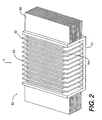
- FIG. 2 shows an isometric view of an alternate embodiment of a heat exchanger 60 in accordance with the present invention.
- Heat exchanger 60 includes contact portion 61 and first and second groups of fins 62 and 66 respectively.
- First group of fins 62 are mounted vertically, while second group of fins 66 are mounted horizontally.
- first group of fins 62 are separated from one another by an air gap so that cooling air may flow freely (along direction A ) between the fins.
- Second group of fins 66 are similarly separated from one another by an air gap so that cooling air may flow freely (along direction A ) between the fins.
- the first group of fins include fins of a first length interspersed between fins of a second length, the first length being shorter than the second length.
- first group of fins 62 includes long fins 65 with short fins 64 interspersed therebetween.
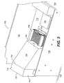
- Fig. 3 is a perspective view of a cooling system for a semiconductor die carrier in accordance with the present invention.
- Fig. 3 shows computer enclosure 700 which includes panels 702, 704, and 706.
- Printed circuit boards (PCBs) 708 and 710 are mounted within computer enclosure 700.
- Semiconductor die carriers 720 and 730 are mounted to PCB 710 .
- a cooling system for a semiconductor die carrier includes a cooling fan disposed at a substantial distance from a semiconductor die carrier, a cooling duct including an inlet portion and an outlet portion, the cooling duct inlet portion attached to the cooling fan, and a heat exchanger disposed on an upper surface of the semiconductor die carrier, wherein the cooling duct outlet portion is disposed in close proximity to the heat exchanger such that the cooling fan draws ambient air into the cooling duct and the ambient air exits the cooling duct outlet portion and passes in a heat exchange relationship with the heat exchanger.
- semiconductor die carrier cooling assembly 740 includes cooling fan 742, cooling duct 744, and heat exchanger 746.
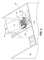
- cooling fan 742 of the present invention is mounted directly to an outer surface of a computer enclosure (outer surface not shown in Figs. 7 and 8 for clarity).
- the cooling fan may be located in numerous other positions/locations without departing from the scope or spirit of the invention in its broader aspects.
- Cooling duct 744 includes inlet portion 752 and outlet portion 754 . Note that cooling duct inlet portion 752 has a greater cross sectional area than cooling duct outlet portion 754 . Thus, optimal airflow characteristics are achieved in the cooling duct 744 .
- cooling fan 742 draws in ambient air through inlet 750 . Cooling air then passes through inlet portion 752 of cooling duct 744 before exiting cooling duct 744 via outlet portion 754. Cooling air flows in direction A across the heat exchanger 746 and in between the fins of heat exchanger 746.
- ambient air the phrase “ambient air” generally refers to cooling air which does not originate from within the computer enclosure
- the axis of fan rotation is also parallel to the upper surface of the semiconductor die carrier 730 .
- other appropriate spatial arrangements of the components may be made without departing from the scope or spirit of the invention in its broader aspects.
- cooling fan 742 is disposed at a substantial distance from semiconductor die carrier 730 , for optimal cooling air flow characteristics.
- a cooling system in accordance with the present invention allows the semiconductor die carrier to be cooled with cooler air (for example 25°C) from outside the computer enclosure rather than conventional systems in which the semiconductor die carrier is cooled with warmer air (for example 45° C) from within the computer enclosure.
Description
- The present invention relates to a cooling system for a semiconductor die carrier.
- Conventional cooling systems for a semiconductor die carrier suffer from several disadvantages. While conventional cooling systems do provide some measure of cooling for semiconductor die carriers, they do not provide optimum cooling capability for the semiconductor die housed in the carrier and optimum performance cannot be achieved. Conventional cooling systems for a semiconductor die carriers rely on a fan mounted adjacent to the die carrier. This close spatial relationship and limitation on airflow passage size reduces the cooling system's ability to effectively remove the heat generated by the die. Furthermore, conventional cooling systems for a semiconductor die carriers rely on the use of warm air from within a computer enclosure to cool the semiconductor die package. Often, the air within the enclosure is substantially warmer than the ambient air outside the computer enclosure. The performance of a semiconductor becomes degraded as the temperature of the die carrier increases. Thus, the above-referenced disadvantages directly effect the performance of the semiconductor die.
- US-A-4674004 discloses a cooling system comprising a cooling fan 16, a cooling duct with inlet and outlet aperture 40 and an heat exchanger 42 (see Fig. 4) mounted on a carrier (PCB) 24, whereby the apertures are disposed upstream and adjacent to the face of the heat exchanger and the heat exchanger comprises fins. Cooling air exiting the aperture impinges onto the face of the hea exchanger in a direction perpendicular thereto an is then carried in opposite directions across the heat exchanger.
- US-A-4715438 shows a heat exchanger 1 which comprises radially oriented on a spreader plate 2 first fins 5f3 (see Fig. 1) of a first length interspersed between second fins 5f1 of a second length. Fig. 2A shows that incomming air strikes the spreader plate 2 in a direction perpendicular thereto and is then dispersed outwardly passing between the fins in a direction parallel thereto.
- Accordingly, there is a need for a cooling system for a semiconductor die carrier with imptoved heat dissipation characteristics.
- Accordingly, the present invention is directed to a cooling system for a semiconductor die carrier as defined in claim 1.
- The cooling system preferably relies upon cool ambient air from the exterior of a computer enclosure to cool the semiconductor die.
- The cooling system further preferably directs the cool ambient air from the exterior of a computer into a heat exchange relationship with the semiconductor die carrier.
- Additional features and advantages of the invention will be set forth in the description which follows, and in part will be apparent from the description, or may be learned by practice of the invention. The objectives and other advantages of the invention will be realized and attained by the structure particularly pointed out in the written description and claims hereof as well as the appended drawings.
- It is to be understood that both the general description above, and the following detailed description are exemplary and explanatory and are intended to provide further explanation of the invention as claimed.
- The accompanying drawings which are included to provide a further understanding of the invention and constitute a part of this specification, illustrate embodiments of the invention and together with the written description, serve to explain the principles of the invention. In the drawings:
- Fig. 1 is an isometric view of a preferred embodiment of a heat exchanger in accordance with the present invention;
- Fig. 2 is an isometric view of an alternate embodiment of a heat exchanger in accordance with the present invention;
- Fig. 3 is a perspective view of a cooling system for a semiconductor die carrier in accordance with the present invention; and
- Fig. 4 is an isometric view of a cooling system for a semiconductor die carrier in accordance with the present invention mounted within a computer enclosure.
-
- Reference will now be made in detail to the preferred embodiments of the present invention, examples of which are illustrated in the accompanying drawings.
- In accordance with the objects of the present invention, the cooling system for a semiconductor die carrier includes a cooling fan disposed at a substantial distance from a semiconductor die carrier, a cooling duct including an inlet portion and an outlet portion, the cooling duct inlet portion attached to the cooling fan, an a heat exchanger disposed on an upper surface of the semiconductor die carrier, wherein the cooling duct outlet portion is disposed in close proximity to the heat exchanger such that the cooling fan draws ambient air into the cooling duct and the ambient air exits the cooling duct outlet portion and passes in a heat exchange relationship with the heat exchanger.
- Fig. 1 shows an isometric view of a preferred embodiment of a
heat exchanger 50 in accordance with the present invention. A heat exchanger according to the present invention includes a contact portion and heat dissipating extensions, wherein the contact portion is adapted to contact an upper surface of a semiconductor die carrier. For example,heat exchanger 50 includescontact portion 52 and first and second groups offins Contact portion 52 is adapted to be mounted to the top surface of a semiconductor die carrier. - A heat exchanger according to the present invention further includes a first and a second group of fins, the first group of fins oriented perpendicularly with respect to the second group of fins. For example, first group of
fins 54 are mounted vertically, while second group offins 58 are mounted horizontally. Furthermore, first group offins 54 are separated from one another by an air gap so that cooling air may flow freely (along direction A) between the fins. Second group offins 58 are similarly separated from one another by an air gap so that cooling air may flow freely (along direction A) between the fins. - In accordance with the present invention, each of the first group of fins includes first and second ends, the first ends of the first group of fins being disposed in a curvilinear array. For example, as is illustrated in Fig. 5, first group of
fins 54 includefirst ends 56 andsecond ends 57. Thefirst ends 56 are arranged in a curvilinear array, while thesecond ends 57 are also arranged in a curvilinear array. This arrangement facilitates a preferred cooling air flow pattern acrossheat exchanger 50.Heat exchanger 50 may be constructed of any appropriate heat conductive material. For example,heat exchanger 50 may be constructed of a metal. Preferably,heat exchanger 50 may be constructed of copper or aluminum. - Fig. 2 shows an isometric view of an alternate embodiment of a
heat exchanger 60 in accordance with the present invention.Heat exchanger 60 includescontact portion 61 and first and second groups offins fins 62 are mounted vertically, while second group offins 66 are mounted horizontally. Furthermore, first group offins 62 are separated from one another by an air gap so that cooling air may flow freely (along direction A) between the fins. Second group offins 66 are similarly separated from one another by an air gap so that cooling air may flow freely (along direction A) between the fins. - In accordance with the present invention, the first group of fins include fins of a first length interspersed between fins of a second length, the first length being shorter than the second length. For example, as shown in Fig. 6, first group of
fins 62 includeslong fins 65 withshort fins 64 interspersed therebetween. - Fig. 3 is a perspective view of a cooling system for a semiconductor die carrier in accordance with the present invention. Fig. 3 shows
computer enclosure 700 which includespanels computer enclosure 700. Semiconductor diecarriers - A cooling system for a semiconductor die carrier according to the present invention includes a cooling fan disposed at a substantial distance from a semiconductor die carrier, a cooling duct including an inlet portion and an outlet portion, the cooling duct inlet portion attached to the cooling fan, and a heat exchanger disposed on an upper surface of the semiconductor die carrier, wherein the cooling duct outlet portion is disposed in close proximity to the heat exchanger such that the cooling fan draws ambient air into the cooling duct and the ambient air exits the cooling duct outlet portion and passes in a heat exchange relationship with the heat exchanger. For example, as shown in Figs. 3 and 4, semiconductor die
carrier cooling assembly 740 includescooling fan 742,cooling duct 744, andheat exchanger 746. Preferably thecooling fan 742 of the present invention is mounted directly to an outer surface of a computer enclosure (outer surface not shown in Figs. 7 and 8 for clarity). However, the cooling fan may be located in numerous other positions/locations without departing from the scope or spirit of the invention in its broader aspects.Cooling duct 744 includesinlet portion 752 andoutlet portion 754. Note that coolingduct inlet portion 752 has a greater cross sectional area than coolingduct outlet portion 754. Thus, optimal airflow characteristics are achieved in the coolingduct 744. - In operation, cooling
fan 742 draws in ambient air throughinlet 750. Cooling air then passes throughinlet portion 752 of coolingduct 744 before exiting coolingduct 744 viaoutlet portion 754. Cooling air flows in direction A across theheat exchanger 746 and in between the fins ofheat exchanger 746. Preferably, ambient air ( the phrase "ambient air" generally refers to cooling air which does not originate from within the computer enclosure) flows in a direction which is parallel to the upper surface of thesemiconductor die carrier 730. Thus preferably, the axis of fan rotation is also parallel to the upper surface of thesemiconductor die carrier 730. However, other appropriate spatial arrangements of the components may be made without departing from the scope or spirit of the invention in its broader aspects. Note that coolingfan 742 is disposed at a substantial distance from semiconductor diecarrier 730, for optimal cooling air flow characteristics. A cooling system in accordance with the present invention allows the semiconductor die carrier to be cooled with cooler air (for example 25°C) from outside the computer enclosure rather than conventional systems in which the semiconductor die carrier is cooled with warmer air (for example 45° C) from within the computer enclosure. - It will be apparent to those skilled in the art that various modifications and variations can be made in the cooling system for a semiconductor die carrier of the present invention without departing from the scope of the invention. Thus, it is intended that the present invention cover the modifications and variations of this invention provided they come within the scope of the appended claims and their equivalents.
Claims (13)
- A cooling system for a semiconductor die carrier (730) comprising:a cooling fan (742) disposed at a substantial distance from a semiconductor die carrier (730);a cooling duct (744) comprising an inlet portion (752) and an outlet portion (754), said inlet portion (752) having a first cross sectional area, said outlet portion (754) having a second cross-sectional area, said first cross-sectional area being greater than said second cross-sectional area, said cooling duct inlet portion (752) attached to said cooling fan; anda heat exchanger (50; 60; 746) disposed on an upper surface of the semiconductor die carrier (730), wherein said heat exchanger (50; 60; 746) comprises a plurality of fins (54; 58; 62; 66) that comprise a first group of fins (54; 62) aligned in a first direction (A) parallel to one another and to said upper surface of the semiconductor die carrier (730), characterized in that said cooling duct outlet portion (754) is disposed adjacent to an edge of said heat exchanger (50; 60; 746) such that ambient air drawn by said cooling fan (742) into said cooling duct (744) exits said cooling duct outlet portion (754) in said first direction (A) and passes along said heat exchanger (50; 60; 746) in said first direction (A) freely between said fins of said first group (54; 62).
- The cooling system of claim 1, whereby said plurality of fins (54; 58; 62; 66) also comprises a second group of parallel fins (58; 66) aligned along said first direction (A), said second group of fins (58; 66) being disposed perpendicularly to said first group of fins (54; 62).
- The cooling system of claim 1, wherein said cooling fan (742) comprises an axis of fan rotation, said axis of fan rotation being oriented parallel to said upper surface of the semiconductor die carrier (730).
- The cooling system of claim 1, wherein said cooling fan (742) is attached to an outer surface of a computer enclosure.
- The cooling system of claim 1, wherein said first and second cross sectional areas are rectangular in shape.
- The cooling system of claim 1, wherein said heat exchanger (50; 60; 746) further comprises a contact portion, said contact portion adapted to contact said upper surface of the semiconductor die carrier (730).
- The cooling system of claim 1, wherein each of said first group of fins comprises first (56) and second ends (57), the first ends (56) of said first group of fins being disposed in a curvilinear array.
- The cooling system of claim 7, wherein second ends (57) of said first group of fins are disposed in a curvilinear array.
- The cooling system of claim 1, wherein said first group of fins (54; 62) comprises fins (54; 64) of a first length interspersed between fins (54; 65) of a second length, said first length being shorter than said second length.
- The cooling system of claim 1, wherein said heat exchanger is formed from a metal.
- The cooling system of claim 10, wherein said heat exchanger (50; 60; 746) is formed from an alloy.
- The cooling system of claim 10, wherein said heat exchanger (50; 60; 746) is formed from aluminum.
- The cooling system of claim 10, wherein said heat exchanger (50; 60; 746) is formed from copper.
Applications Claiming Priority (3)
| Application Number | Priority Date | Filing Date | Title |
|---|---|---|---|
| US970503 | 1997-11-14 | ||
| US08/970,503 US6031720A (en) | 1997-11-14 | 1997-11-14 | Cooling system for semiconductor die carrier |
| PCT/US1998/024251 WO1999026460A1 (en) | 1997-11-14 | 1998-11-13 | Cooling system for semiconductor die carrier |
Publications (3)
| Publication Number | Publication Date |
|---|---|
| EP1036491A1 EP1036491A1 (en) | 2000-09-20 |
| EP1036491A4 EP1036491A4 (en) | 2001-05-16 |
| EP1036491B1 true EP1036491B1 (en) | 2004-06-23 |
Family
ID=25517044
Family Applications (1)
| Application Number | Title | Priority Date | Filing Date |
|---|---|---|---|
| EP98958566A Expired - Lifetime EP1036491B1 (en) | 1997-11-14 | 1998-11-13 | Cooling system for semiconductor die carrier |
Country Status (7)
| Country | Link |
|---|---|
| US (1) | US6031720A (en) |
| EP (1) | EP1036491B1 (en) |
| JP (1) | JP2001523897A (en) |
| KR (1) | KR20010024613A (en) |
| AU (1) | AU1458399A (en) |
| DE (1) | DE69824758D1 (en) |
| WO (1) | WO1999026460A1 (en) |
Families Citing this family (32)
| Publication number | Priority date | Publication date | Assignee | Title |
|---|---|---|---|---|
| TW484721U (en) * | 2000-11-06 | 2002-04-21 | Giga Byte Tech Co Ltd | Improved airflow guiding structure of server |
| DE10063306A1 (en) * | 2000-12-19 | 2002-07-04 | Fujitsu Siemens Computers Gmbh | cooler |
| WO2003015488A1 (en) * | 2001-08-09 | 2003-02-20 | Celestica International Inc. | Electronics cooling subassembly |
| AU2002326749A1 (en) | 2001-08-09 | 2003-02-24 | Celestica International Inc. | Heat removal system |
| WO2003030608A1 (en) * | 2001-10-04 | 2003-04-10 | Celestica International Inc. | Cooling system having independent fan location |
| US7064953B2 (en) * | 2001-12-27 | 2006-06-20 | Formfactor, Inc. | Electronic package with direct cooling of active electronic components |
| US6891385B2 (en) * | 2001-12-27 | 2005-05-10 | Formfactor, Inc. | Probe card cooling assembly with direct cooling of active electronic components |
| JP2003258169A (en) * | 2002-03-05 | 2003-09-12 | Fujikura Ltd | Heat sink |
| US6661665B2 (en) * | 2002-03-11 | 2003-12-09 | Sun Microsystems, Inc. | Method and apparatus for removing heat from an electronic device |
| US6975509B2 (en) * | 2002-05-16 | 2005-12-13 | Sun Microsystems, Inc. | Computing apparatus with cooling fan |
| US6678157B1 (en) * | 2002-09-17 | 2004-01-13 | Sun Microsystems, Inc. | Electronics assembly with cooling arrangement |
| KR20040038162A (en) * | 2002-10-31 | 2004-05-08 | 삼성전자주식회사 | Main body of computer |
| KR100939992B1 (en) * | 2002-11-21 | 2010-02-03 | 삼성전자주식회사 | Cooling Apparatus, and Electric-Electronic Equipment with the Cooling Apparatus |
| JP4411147B2 (en) * | 2004-06-24 | 2010-02-10 | 株式会社日立製作所 | Heat sink with fan |
| CN2720626Y (en) * | 2004-06-25 | 2005-08-24 | 鸿富锦精密工业(深圳)有限公司 | Radiator |
| US20060098414A1 (en) * | 2004-11-10 | 2006-05-11 | Meng-Cheng Huang | Heat sink |
| TWI268995B (en) * | 2004-12-24 | 2006-12-21 | Foxconn Tech Co Ltd | Fan duct device |
| CN100464279C (en) * | 2005-11-17 | 2009-02-25 | 富准精密工业(深圳)有限公司 | Heat sink |
| US7251136B2 (en) * | 2005-12-29 | 2007-07-31 | Fu Zhun Precision Industry (Shen Zhen) Co., Ltd. | Heat dissipation device having a ventilating duct |
| US7228889B1 (en) | 2006-01-09 | 2007-06-12 | Fu Zhun Precision Industry (Shen Zhen) Co., Ltd. | Heat dissipation device |
| KR101110434B1 (en) * | 2006-05-02 | 2012-02-24 | 엘지전자 주식회사 | Computer cooling device |
| US20080112134A1 (en) * | 2006-11-09 | 2008-05-15 | Brandon Rubenstein | Dust accumulation resistant heat sink |
| US7806167B2 (en) * | 2007-06-22 | 2010-10-05 | Fu Zhun Precision Industry (Shen Zhen) Co., Ltd. | Heat dissipation device |
| DE112011101959B4 (en) * | 2010-06-07 | 2016-11-24 | Mitsubishi Electric Corporation | Heat sink and process for its production |
| CN102654790A (en) * | 2011-03-03 | 2012-09-05 | 鸿富锦精密工业(深圳)有限公司 | Heat radiation system |
| US9871358B2 (en) * | 2015-01-30 | 2018-01-16 | Abb Schweiz Ag | Electrical switchgear system |
| BR112018003099A2 (en) | 2015-08-25 | 2018-09-25 | Nokia Solutions And Networks Oy | radio frame setting |
| JP6855873B2 (en) * | 2017-03-27 | 2021-04-07 | 富士電機株式会社 | Electric power converter for railway vehicles |
| JP6988148B2 (en) * | 2017-04-24 | 2022-01-05 | 富士電機株式会社 | Power converter for railroad vehicles |
| CN108932039B (en) * | 2017-05-26 | 2021-08-13 | 鸿富锦精密工业(武汉)有限公司 | Wind scooper and heat dissipation system |
| JP6888468B2 (en) * | 2017-08-01 | 2021-06-16 | 富士電機株式会社 | Power converter for railroad vehicles |
| JP2022178278A (en) * | 2021-05-19 | 2022-12-02 | 日本電産株式会社 | Heat radiation member |
Family Cites Families (12)
| Publication number | Priority date | Publication date | Assignee | Title |
|---|---|---|---|---|
| US4715438A (en) * | 1986-06-30 | 1987-12-29 | Unisys Corporation | Staggered radial-fin heat sink device for integrated circuit package |
| US4674004A (en) * | 1986-07-03 | 1987-06-16 | Burroughs Corporation | Parallel-flow air system for cooling electronic equipment |
| US5077601A (en) * | 1988-09-09 | 1991-12-31 | Hitachi, Ltd. | Cooling system for cooling an electronic device and heat radiation fin for use in the cooling system |
| JPH0412559A (en) * | 1990-05-01 | 1992-01-17 | Fujitsu Ltd | Cooling structure of electronic device |
| JPH0521665A (en) * | 1991-07-11 | 1993-01-29 | Nec Corp | Semiconductor package provided with heat sink |
| US5428503A (en) * | 1992-03-24 | 1995-06-27 | Hitachi, Ltd. | Jet cooling apparatus for cooling electronic equipment and computer having the same mounted thereon |
| JP2596682B2 (en) * | 1992-09-08 | 1997-04-02 | 株式会社日立製作所 | Electronic equipment cooling device |
| JP3236137B2 (en) * | 1993-07-30 | 2001-12-10 | 富士通株式会社 | Semiconductor element cooling device |
| JPH08236664A (en) * | 1995-02-23 | 1996-09-13 | Toshiba Corp | Cooler for semiconductor |
| US5597035A (en) * | 1995-08-18 | 1997-01-28 | Dell Usa, L.P. | For use with a heatsink a shroud having a varying cross-sectional area |
| US5563768A (en) * | 1995-08-31 | 1996-10-08 | At&T Global Information Solutions Company | Heat source cooling apparatus and method utilizing mechanism for dividing a flow of cooling fluid |
| US5828549A (en) * | 1996-10-08 | 1998-10-27 | Dell U.S.A., L.P. | Combination heat sink and air duct for cooling processors with a series air flow |
-
1997
- 1997-11-14 US US08/970,503 patent/US6031720A/en not_active Expired - Fee Related
-
1998
- 1998-11-13 DE DE69824758T patent/DE69824758D1/en not_active Expired - Lifetime
- 1998-11-13 AU AU14583/99A patent/AU1458399A/en not_active Abandoned
- 1998-11-13 EP EP98958566A patent/EP1036491B1/en not_active Expired - Lifetime
- 1998-11-13 JP JP2000521685A patent/JP2001523897A/en active Pending
- 1998-11-13 KR KR1020007005249A patent/KR20010024613A/en not_active Application Discontinuation
- 1998-11-13 WO PCT/US1998/024251 patent/WO1999026460A1/en active IP Right Grant
Also Published As
| Publication number | Publication date |
|---|---|
| AU1458399A (en) | 1999-06-07 |
| JP2001523897A (en) | 2001-11-27 |
| DE69824758D1 (en) | 2004-07-29 |
| KR20010024613A (en) | 2001-03-26 |
| EP1036491A1 (en) | 2000-09-20 |
| WO1999026460A1 (en) | 1999-05-27 |
| WO1999026460A8 (en) | 1999-07-01 |
| US6031720A (en) | 2000-02-29 |
| EP1036491A4 (en) | 2001-05-16 |
Similar Documents
| Publication | Publication Date | Title |
|---|---|---|
| EP1036491B1 (en) | Cooling system for semiconductor die carrier | |
| JP3278809B2 (en) | Foldable fin-shaped heat sink and heat exchanger using the same | |
| US6778390B2 (en) | High-performance heat sink for printed circuit boards | |
| US6871702B2 (en) | Heat dissipator | |
| US5604665A (en) | Multiple parallel impingement flow cooling with tuning | |
| JP3851875B2 (en) | Cooling device and electronic equipment | |
| US6157539A (en) | Cooling apparatus for electronic devices | |
| US20040200601A1 (en) | Heat sink assembly | |
| US6668910B2 (en) | Heat sink with multiple surface enhancements | |
| US6446708B1 (en) | Heat dissipating device | |
| US20080023176A1 (en) | Heat dissipation device | |
| JP2004538657A (en) | Electronic device cooling structure | |
| US20040200608A1 (en) | Plate fins with vanes for redirecting airflow | |
| JPH02201999A (en) | Cooling plane device for cooling electronic circuit parts | |
| US5873407A (en) | Windblown-type heat-dissipating device for computer mother board | |
| JP2003142637A (en) | Cooling structure of heat sink and heating element | |
| US5508883A (en) | Air mixer cool plate | |
| KR0136070B1 (en) | Electronic equipment | |
| JP2735306B2 (en) | Substrate cooling device | |
| US5229914A (en) | Cooling device that creates longitudinal vortices | |
| JP2685918B2 (en) | Heat pipe cooler | |
| JP2895388B2 (en) | PCB cooling structure | |
| JPH11186762A (en) | Cover for heat sink | |
| JP2000091776A (en) | Cooling fin for electronic device | |
| JPH1098139A (en) | Forcedly air cooled structure and electronic equipment thereof |
Legal Events
| Date | Code | Title | Description |
|---|---|---|---|
| PUAI | Public reference made under article 153(3) epc to a published international application that has entered the european phase |
Free format text: ORIGINAL CODE: 0009012 |
|
| 17P | Request for examination filed |
Effective date: 20000518 |
|
| AK | Designated contracting states |
Kind code of ref document: A1 Designated state(s): DE FR GB IT NL |
|
| A4 | Supplementary search report drawn up and despatched |
Effective date: 20010402 |
|
| AK | Designated contracting states |
Kind code of ref document: A4 Designated state(s): DE FR GB IT NL |
|
| RIC1 | Information provided on ipc code assigned before grant |
Free format text: 7H 05K 7/20 A, 7H 01L 23/367 B, 7H 01L 23/467 B |
|
| RAP1 | Party data changed (applicant data changed or rights of an application transferred) |
Owner name: SILICON BANDWIDTH, INC. |
|
| 17Q | First examination report despatched |
Effective date: 20020724 |
|
| GRAP | Despatch of communication of intention to grant a patent |
Free format text: ORIGINAL CODE: EPIDOSNIGR1 |
|
| GRAS | Grant fee paid |
Free format text: ORIGINAL CODE: EPIDOSNIGR3 |
|
| GRAA | (expected) grant |
Free format text: ORIGINAL CODE: 0009210 |
|
| AK | Designated contracting states |
Kind code of ref document: B1 Designated state(s): DE FR GB IT NL |
|
| PG25 | Lapsed in a contracting state [announced via postgrant information from national office to epo] |
Ref country code: NL Free format text: LAPSE BECAUSE OF FAILURE TO SUBMIT A TRANSLATION OF THE DESCRIPTION OR TO PAY THE FEE WITHIN THE PRESCRIBED TIME-LIMIT Effective date: 20040623 Ref country code: IT Free format text: LAPSE BECAUSE OF FAILURE TO SUBMIT A TRANSLATION OF THE DESCRIPTION OR TO PAY THE FEE WITHIN THE PRE;WARNING: LAPSES OF ITALIAN PATENTS WITH EFFECTIVE DATE BEFORE 2007 MAY HAVE OCCURRED AT ANY TIME BEFORE 2007. THE CORRECT EFFECTIVE DATE MAY BE DIFFERENT FROM THE ONE RECORDED.SCRIBED TIME-LIMIT Effective date: 20040623 Ref country code: FR Free format text: LAPSE BECAUSE OF FAILURE TO SUBMIT A TRANSLATION OF THE DESCRIPTION OR TO PAY THE FEE WITHIN THE PRESCRIBED TIME-LIMIT Effective date: 20040623 |
|
| REG | Reference to a national code |
Ref country code: GB Ref legal event code: FG4D |
|
| REF | Corresponds to: |
Ref document number: 69824758 Country of ref document: DE Date of ref document: 20040729 Kind code of ref document: P |
|
| PG25 | Lapsed in a contracting state [announced via postgrant information from national office to epo] |
Ref country code: DE Free format text: LAPSE BECAUSE OF FAILURE TO SUBMIT A TRANSLATION OF THE DESCRIPTION OR TO PAY THE FEE WITHIN THE PRESCRIBED TIME-LIMIT Effective date: 20040924 |
|
| PG25 | Lapsed in a contracting state [announced via postgrant information from national office to epo] |
Ref country code: GB Free format text: LAPSE BECAUSE OF NON-PAYMENT OF DUE FEES Effective date: 20041113 |
|
| NLV1 | Nl: lapsed or annulled due to failure to fulfill the requirements of art. 29p and 29m of the patents act | ||
| PLBE | No opposition filed within time limit |
Free format text: ORIGINAL CODE: 0009261 |
|
| STAA | Information on the status of an ep patent application or granted ep patent |
Free format text: STATUS: NO OPPOSITION FILED WITHIN TIME LIMIT |
|
| 26N | No opposition filed |
Effective date: 20050324 |
|
| EN | Fr: translation not filed | ||
| GBPC | Gb: european patent ceased through non-payment of renewal fee |
Effective date: 20041113 |