EP1035518B1 - Arrangement for the protection of a security module - Google Patents
Arrangement for the protection of a security module Download PDFInfo
- Publication number
- EP1035518B1 EP1035518B1 EP00250065A EP00250065A EP1035518B1 EP 1035518 B1 EP1035518 B1 EP 1035518B1 EP 00250065 A EP00250065 A EP 00250065A EP 00250065 A EP00250065 A EP 00250065A EP 1035518 B1 EP1035518 B1 EP 1035518B1
- Authority
- EP
- European Patent Office
- Prior art keywords
- security module
- voltage
- battery
- processor
- line
- Prior art date
- Legal status (The legal status is an assumption and is not a legal conclusion. Google has not performed a legal analysis and makes no representation as to the accuracy of the status listed.)
- Expired - Lifetime
Links
Images


Classifications
-
- G—PHYSICS
- G07—CHECKING-DEVICES
- G07B—TICKET-ISSUING APPARATUS; FARE-REGISTERING APPARATUS; FRANKING APPARATUS
- G07B17/00—Franking apparatus
- G07B17/00733—Cryptography or similar special procedures in a franking system
-
- G—PHYSICS
- G07—CHECKING-DEVICES
- G07B—TICKET-ISSUING APPARATUS; FARE-REGISTERING APPARATUS; FRANKING APPARATUS
- G07B17/00—Franking apparatus
- G07B17/00185—Details internally of apparatus in a franking system, e.g. franking machine at customer or apparatus at post office
- G07B17/00193—Constructional details of apparatus in a franking system
- G07B2017/00233—Housing, e.g. lock or hardened casing
-
- G—PHYSICS
- G07—CHECKING-DEVICES
- G07B—TICKET-ISSUING APPARATUS; FARE-REGISTERING APPARATUS; FRANKING APPARATUS
- G07B17/00—Franking apparatus
- G07B17/00185—Details internally of apparatus in a franking system, e.g. franking machine at customer or apparatus at post office
- G07B17/00193—Constructional details of apparatus in a franking system
- G07B2017/00266—Man-machine interface on the apparatus
- G07B2017/00298—Visual, e.g. screens and their layouts
-
- G—PHYSICS
- G07—CHECKING-DEVICES
- G07B—TICKET-ISSUING APPARATUS; FARE-REGISTERING APPARATUS; FRANKING APPARATUS
- G07B17/00—Franking apparatus
- G07B17/00185—Details internally of apparatus in a franking system, e.g. franking machine at customer or apparatus at post office
- G07B17/00193—Constructional details of apparatus in a franking system
- G07B2017/00266—Man-machine interface on the apparatus
- G07B2017/00306—Acoustic, e.g. voice control or speech prompting
-
- G—PHYSICS
- G07—CHECKING-DEVICES
- G07B—TICKET-ISSUING APPARATUS; FARE-REGISTERING APPARATUS; FRANKING APPARATUS
- G07B17/00—Franking apparatus
- G07B17/00185—Details internally of apparatus in a franking system, e.g. franking machine at customer or apparatus at post office
- G07B17/00314—Communication within apparatus, personal computer [PC] system, or server, e.g. between printhead and central unit in a franking machine
- G07B2017/00346—Power handling, e.g. power-down routine
-
- G—PHYSICS
- G07—CHECKING-DEVICES
- G07B—TICKET-ISSUING APPARATUS; FARE-REGISTERING APPARATUS; FRANKING APPARATUS
- G07B17/00—Franking apparatus
- G07B17/00185—Details internally of apparatus in a franking system, e.g. franking machine at customer or apparatus at post office
- G07B17/00362—Calculation or computing within apparatus, e.g. calculation of postage value
- G07B2017/00395—Memory organization
- G07B2017/00403—Memory zones protected from unauthorized reading or writing
-
- G—PHYSICS
- G07—CHECKING-DEVICES
- G07B—TICKET-ISSUING APPARATUS; FARE-REGISTERING APPARATUS; FRANKING APPARATUS
- G07B17/00—Franking apparatus
- G07B17/00733—Cryptography or similar special procedures in a franking system
- G07B2017/00959—Cryptographic modules, e.g. a PC encryption board
- G07B2017/00967—PSD [Postal Security Device] as defined by the USPS [US Postal Service]
Definitions
- the invention relates to an arrangement for protecting a security module, according to claim 1.
- a postal security module is particularly suitable for use in a postage meter or mail processing machine or computer with mail processing function.
- Modern franking machines like those from the US 4,746,234 known thermal transfer postage meter, employ a fully electronic digital printing device.
- Applicants' T1000 meter has a microprocessor surrounded by a secure housing having an opening for delivering a letter.
- a mechanical letter sensor microwaveswitch
- the franking imprint includes previously entered and stored postal information for conveying the letter.
- the control unit of the franking machine carries out a software billing, exercises a monitoring function, possibly with regard to the conditions for a data update, and controls the reloading of a port value credit.
- thermal transfer franking machine has already been in US 5,606,508 ( DE 42 13 278 B1 ) and in US 5,490,077 proposed a data entry option using smart cards.
- One of the smart cards loads new data into the postage meter machine and a set of further smart cards allows a setting to be made according to stored data by inserting a chip card.
- the data loading and the setting of the franking machine can thus be more convenient and faster than by keyboard input.
- a franking machine for franking mail is provided with a printer for printing the postage stamp on the mail, a controller for controlling the printing and peripheral components of the postage meter, a bill unit for settling postage, at least one nonvolatile memory for storing postage data , equipped with at least one non-volatile memory for storing safety-relevant data and with a calendar / clock.
- the non-volatile memory of the safety-related data and / or the calender / clock is usually powered by a battery.
- security-relevant data (cryptographic keys and the like) are saved in nonvolatile memories. These memories are EEPROM, FRAM or battery backed SRAM.
- Known franking machines often also have an internal real time clock (RTC), which is powered by a battery.
- RTC real time clock
- encapsulated modules containing integrated circuits and a lithium battery. These modules must be replaced and disposed of at the end of the life of the battery as a whole. From an economic and ecological point of view, it is better if only the battery needs to be replaced.
- the security case must be opened and then closed again and sealed, because the security against fraud is essentially based on the secure housing, which encloses the entire machine.
- EP 660 269 A2 US 5,671,146
- any required repair of a franking machine is then difficult on site, if the access to the components is difficult or limited.
- the secured housing will in future be reduced to the so-called postal security module, which can improve the accessibility to the other components.
- the battery of the security module it would also be desirable that these be relatively simple can be replaced.
- the battery must be outside the security range of the franking machine.
- a potential attacker is able to manipulate the battery voltage.
- Known battery-powered SRAM and RTC have different requirements with regard to their required operating voltage. The voltage required to hold data from SRAM is below the required voltage for operating RTC.
- the enifernte data center specifies a time credit or a period of time, in particular a number of days, or a specific day up to which the franking device can report via communication link. After unsuccessful expiration of the time credit or the deadline, franking is prevented.
- Security modules are already known from electronic data processing systems ago. To protect against burglary in an electronic system is in EP 417 447 B1 already proposed a lock, which includes power supply and signal detection means and shielding in the housing.
- the shielding means is made of encapsulating material and conductive means to which the power supply and signal detection means are connected. The latter responds to a change in the line resistance of the line means.
- the security module contains an internal battery, a voltage switch from system voltage to battery voltage, a power gate and a short-circuit transistor as well as other sensors. When the voltage falls below a certain limit, the Power Gate responds. If the line resistance, temperature or radiation is changed, the logic will react.
- the output of the short-circuit transistor is switched to L level, whereby a memory stored in the cryptographic key is deleted.
- the life of the non-replaceable battery and thus of the security module for use in franking devices or mail processing machines is too small.
- a larger mail processing machine is, for example, the JetMail®.
- a franking print is here produced by means of a stationary ink jet printhead in a non-horizontal approximately vertical letter transport.
- a suitable design for a printing device was already in the DE 196 05 015 C1 proposed.
- the mailing machine has a meter and a base. If the meter is to be equipped with a housing so that components are more easily accessible, then it must be protected by a postal security module fraud attempts, which at least performs the settlement of postal fees. To exclude influences on the program, has already been in the EP 789 333 A2 under the title: Postage meter proposed to equip a security module with an Application Specific Integrated Circuit ASIC, which has a hardware A réelleaji. The user circuit also controls the print data transfer to the print head.
- franking machines are also modular. This modularity allows the exchange of modules and components for various reasons. Thus, e.g. defective modules are replaced and replaced by checked, repaired or new modules. Since the utmost care is required in the exchange of assemblies containing safety-relevant data, the replacement usually requires the use of a service technician and measures that prevent its functioning in case of improper use or unauthorized replacement of a security module. The latter is very expensive.
- the invention has for its object, with little effort to ensure protection against an unauthorized manipulated security module when the security module is arranged interchangeable.
- the exchange should be possible by anyone in the simplest possible way.
- the invention assumes, by means of functional units, the exchange, the manipulation and the use of a security module of a franking machine, mail processing device or similar device in order to provide users of the various devices with a guarantee about the correct functioning of the security module and thus of the entire device.
- Exchanging or damaging the safety module is at least detected and, if necessary, subsequently signaled as a state when the safety module is plugged in again and supplied with a system voltage.
- the changes in the state of the security module are detected by means of a first functional unit and by means of a detection unit, which has a resettable latching and is powered by a battery.
- the first functional unit can evaluate the respective state when it is supplied with system voltage again.
- a second functional unit may optionally monitor the battery voltage to see if its capacity has been exhausted. A required battery change is signaled, of course, a supply must be backed up by the system voltage. It is to be assumed at least then of an improper use of a security module in the exchange, in which not only the system voltage is missing, but also the interchangeable battery is removed. So that the replacement of the lowest possible qualified personnel and in the future can even be performed by the user, the second functional unit monitors the power failure when replacing the battery, the first functional unit, if necessary, first deletes sensitive data and thus restricts the further use of the security module or even prevented. After an on-site inspection of the security module by a service, the original functionality can be restored with the housing intact.
- the first functional unit enforces a later re-commissioning contact the security module with a remote data center to unlock at least one functional unit. If the entire security module has been exchanged without changing the battery, sensitive data is also first deleted by the second functional unit, but the sensitive data can be reinitialized during the restart. To establish contact methods with a digital or analog transmission link can be used. Also, an inspection of the security module is then by a Service causes. The safety module can signal different states. For example, a distinction can be made as to whether the last contact with the data center was made so long ago that it already seems suspicious or long that reinitialization is no longer permitted. The first functional unit is constantly evaluating a first day loan. When the latter is exhausted, the suspicious state is signaled.
- the time credit can be variable and vary from security device to security device.
- the time credit can be specified by the data center and loaded during installation into a memory of the security device.
- the first functional unit constantly evaluates a second daily loan. When the latter is exhausted, the state "LOST" is signaled. In the latter case, an inspection of the security module by a local service is also required.
- the security module protection assembly comprises the security module having logic means for supplying the security module with a system voltage or with a voltage from a battery and with a number of monitoring means. It is described by at least a first and a second functional unit and by means for loading at least one time credit specified by the data center and by a signal means connected to a first functional unit, the charging being performed during installation and reloading into a memory of the security device is, and wherein the first functional unit evaluates a day loan on time and the signal means controls, at least to signal the timing, and by means of the second functional unit for deleting sensitive data in memory due improper use or replacement of the security module.
- FIG. 1 is a block diagram of the security module 100 with the contact groups 101, 102 for connection to an interface 8 and with the battery contact terminals 103 and 104 of a battery interface for a battery 134 shown.
- the security module 100 is potted with a hard potting compound, the battery 134 of the security module 100 is interchangeably disposed outside of the potting compound on a printed circuit board.
- the circuit board carries the battery contact terminals 103 and 104 for connecting the poles of the battery 134.
- the security module 100 is plugged into a corresponding interface 8 of the motherboard (motherboard) 9.
- the first contact group 101 communicates with the system bus of a control device and the second contact group 102 serves to supply the security module 100 with the system voltage.
- the first and / or second contact group 101 and / or 102 are / is designed for static and dynamic monitoring of the plugged in the security module 100.
- the supply of the security module 100 is realized with the system voltage of the motherboard 9 and the pins P1, P2 and P4, a dynamic and static non-detection detected by the security module 100.
- the latter requires a detection unit 13, which is connected via a conductor loop 192, 194 to the pin P4 of the contact group 102.
- the conductor loop may be formed as part of the particular secure part of the security module 100 and embedded in sealing compound so that in a mechanical or chemical attack on the aforementioned part of the security module 100, the contact with the pin P4 is interrupted.
- the security module 100 has, in a manner known per se, a microprocessor 120 which contains an integrated read-only memory (internal ROM) with the special application program (not shown), which is approved for the franking machine by the postal authority or the respective mail carrier. Alternatively, a conventional read-only memory ROM or FLASH memory can be connected to the internal data bus 126.
- the security module 100 has, in a manner known per se, a reset circuit unit 130, a user circuit ASIC 150 and a logic PAL 160 which serves as the control signal generator for the ASIC.
- the reset circuit unit 130 and the user circuit ASIC 150 and the logic PAL 160 and possibly other - not shown - memory are supplied via the lines 191 and 129 with system voltage Us +, which is supplied from the motherboard 9 when the franking device is turned on.
- system voltage Us + which is supplied from the motherboard 9 when the franking device is turned on.
- the system voltage Us + is also applied via a diode 181 and the line 136 at the input of the voltage monitoring unit 12.
- a second operating voltage Ub + is supplied, which is available via the line 138.
- the negative terminal battery contact terminal 104 is connected to ground. From the battery contact terminal 103 lying on the positive pole, battery voltage is supplied via a line 193, via a second diode 182 and the line 136 to the input of the voltage monitoring unit.
- a commercial circuit can be used as a voltage switch 180.
- the output of the voltage monitoring unit 12 is connected via a line 138 to an input for this second operating voltage U b + of the processor 120, which leads at least to a RAM memory area 122, 124 and there guarantees non-volatile storage as long as the second operating voltage U b + in the required Height is applied.
- the processor 120 preferably includes an internal RAM 124 and a real-time clock (RTC) 122.
- the voltage monitoring unit 12 in the security module has a resettable latching, which can be queried by the processor 120 via a line 164 and reset via a line 135. For a reset of the latching, the voltage monitoring unit 12 has circuit means. The reset can only be triggered when the battery voltage has risen above the predetermined threshold.
- the lines 135 and 164 are each connected to a pin (pins 1 and 2) of the processor 120. Line 164 provides a status signal to processor 120, and line 135 provides a control signal to voltage monitoring unit 12.
- the line 136 at the input of the voltage monitoring unit 12 also supplies an unplugged detection unit 13 with operating or battery voltage.
- the unplugged detection unit 13 outputs on the line 139 a status signal to a pin 5 of the processor 120, which gives an indication of the state of the circuit.
- the processor 120 queries the state of the unplugged detection unit 13 via the line 139.
- the processor may reset the unplugged detection unit 13 with a signal output from the pin 4 of the processor 120 via the lead 137.
- a static check is made for connection.
- ground potential is queried via a line 192, which is present at the connection P4 of the interface 8 of the postal security module PSM 100 and can only be interrogated if the security module 100 is inserted properly.
- ground potential of the negative pole 104 of the battery 134 of the postal security module PSM 100 is placed on the port P23 of the interface 8 and is thus interrogated at port P4 of the interface 8 via the line 192 of the unplugged detection unit 13.
- a line loop which is looped back to the processor 120 via the pins P1 and P2 of the contact group 102 of the interface 8.
- the processor 120 For dynamic testing of the connectedness of the postal security module PSM 100 to the motherboard 9, the processor 120 generates alternating signal levels at quite irregular time intervals at the pins 6, 7 and looping them back through the loop.
- the postal security module PSM 100 is equipped with a long-live battery, which also allows monitoring of the use without the security module is connected to a system voltage of a postal processing facility. Proper use, operation, installation or installation in the appropriate environment are those characteristics to be tested by the functional units of the safety module. An initial installation is made by the manufacturer of the postal security module.
- the processor 120 Since in a mechanical or chemical attack on the security module 100 and for each separation of the security module 100 from the interface unit 8, the storage of this information by the special battery-powered circuitry is ensured, an evaluation of this information can be done at any time, if a restart is desired ,
- the regular evaluation of this disconnection signal on the line 139 of the detection unit 13 makes it possible for the processor 120 to delete sensitive data without, however, changing the billing and customer data in the NVRAM memories.
- the current state of the postal security module with the deleted sensitive data can be understood as a maintenance condition, in which usually the replacement, repair or otherwise is made. Since the sensitive data of the functional unit are deleted, an error due to improper handling of the postal security module is excluded.
- the sensitive data are, for example, cryptographic keys.
- the processor 120 prevents in the maintenance state a core functionality of the postal security module, which consists for example in the billing and / or calculation of a security code for the security marking in a security print.
- the postal security module PSM is first inserted and electrically connected to the corresponding interface unit 8 of a mail processing device. Then the device is switched on and thus the postal security module is again supplied with system voltage Us +. Due to the special condition, the proper installation of the postal security module must now be rechecked by its functional unit. For this purpose, a second stage of a test (dynamic plug-in detection) is provided. By means of an operative connection established between the first functional unit (processor 120) and the current loop 18 of the interface unit 8, information is exchanged whose error-free transmission provides proof of the proper installation. This is a prerequisite for a successful restart.
- FIG. 2 shows a block diagram of a postage meter, which is equipped with a chip card read / write unit 70 for reloading change data by chip card and with a printing device 2, which is controlled by a control device 1.
- the control device 1 has a motherboard 9 equipped with a microprocessor 91 with associated memories 92, 93, 94, 95.
- the program memory 92 contains an operating program for at least printing and at least safety-related components of the program for a predetermined format change of a portion of the user data.
- the RAM RAM 93 is used for volatile intermediate storage of intermediate results.
- NVM 94 non-volatile memory is used for non-volatile caching of data, such as statistical data organized by cost center.
- the calendar / clock module 95 also contains addressable but non-volatile memory areas for the non-volatile intermediate storage of intermediate results or also known program parts (for example for the DES algorithm).
- control device 1 is connected to the chip card write / read unit 70, wherein the microprocessor 91 of the control device 1 is programmed, for example, to load the payload N from the memory area of a chip card 49 for their application in corresponding memory areas of the franking machine ,
- a first chip card 49 inserted in a slot 72 of the chip card write / read unit 70 allows reloading of a record in the postage meter machine for at least one application.
- the chip card 49 contains, for example, the postage for all the usual postal carrier services according to the tariff of the postal authority and a post carrier code to generate a stamp image with the franking machine and to stamp the postal items according to the tariff of the postal authority.
- the control device 1 forms the actual meter with the means 91 to 95 of the aforementioned motherboard 9 and also includes a keyboard 88, a display unit 89 and an application-specific circuit ASIC 90 and the interface 8 for the postal security module PSM 100.
- the security module PSM 100 is about a control bus to the aforementioned ASIC 90 and the microprocessor 91 and via the parallel ⁇ C bus at least with the means 91 to 95 of the motherboard 9 and connected to the display unit 89.
- the control bus carries lines for the signals CE, RD and WR between the security module PSM 100 and the aforementioned ASIC 90.
- the microprocessor 91 preferably has a pin for an output from the security module PSM 100 interrupt signal i, other connections for the keyboard 88, a
- the serial interface SI-1 for the connection of the chip card write / read unit 70 and a serial interface SI-2 for the optional connection of a MODEM by means of the MODEM can be used to increase the credit stored in the non-volatile memory of the postal security device PSM 100.
- the postal security device PSM 100 is surrounded by a secured housing. Before each franking imprint, a hardware settlement is carried out in the postal security module PSM 100. Billing is independent of cost centers.
- the postal security agent PSM 100 can be designed internally as in the European application EP 789 333 A3 was described in more detail. It is contemplated that the ASIC 90 may include a serial interface circuit 98 to a post-stream powered device, a serial interface circuit 96 to the sensors and actuators of the printing device 2, a serial interface circuit 97 to the print control electronics 16 for the printhead 4, and a serial interface circuit 99 to one has the printing device 20 in the post-stream downstream device.
- the peripheral interface can be removed, which is suitable for multiple peripheral devices (stations). It is entitled: Arrangement for communication between a base station and other stations of a mailing machine and their emergency shutdown.
- the interface circuit 96 coupled to the machine interface in the interface circuit 14 provides at least one connection to the sensors 6, 7, 17 and to the actuators, for example to Drive motor 15 for the roller 11 and to a cleaning and sealing station RDS 40 for the inkjet printhead 4, as well as the label dispenser 50 in the machine base forth
- the basic arrangement and the interaction between the inkjet printhead 4 and the RDS 40 are the DE 197 26 642 C2 removable, entitled: Arrangement for positioning an ink jet printhead and a cleaning and sealing device.
- One of the arranged in the guide plate 20 sensors 7, 17 is the sensor 17 and is used to prepare the pressure release during letter transport.
- the sensor 7 is used for initial letter recognition for the purpose of triggering the letter transport.
- the transport device consists of a conveyor belt 10 and two rollers 11,11 '.
- One of the rollers is equipped with a motor 15 drive roller 11, another is the follower tension roller 11 '.
- the drive roller 11 is designed as a toothed roller, according to the conveyor belt 10 is designed as a toothed belt, which ensures the unambiguous power transmission.
- An encoder 5, 6 is coupled to one of the rollers 11, 11 '.
- the drive roller 11 is firmly seated with an incremental encoder 5 on an axis.
- the incremental encoder 5 is designed for example as a slotted disk, which cooperates with a light barrier 6, and outputs via the line 19 an encoder signal to the motherboard 9 from.
- the individual printing elements of the print head are connected within its housing with a print head electronics and that the print head for a purely electronic pressure can be controlled.
- the pressure control is based on the path control, whereby the selected stamp offset is taken into account, which is entered by keyboard 88 or if necessary by chip card and stored in memory NVM 94 non-volatile.
- a planned imprint thus results from stamp offset (without printing), the franking print image and possibly further print images for advertising clichés, shipping information (optional prints) and additional editable messages.
- the nonvolatile memory NVM 94 has a plurality of memory areas. These include those which save the loaded postage fee tables non-volatile.
- the smart card write / read unit 70 consists of an associated mechanical support for the microprocessor card and contact unit 74. The latter allows a secure mechanical support of the smart card in the read position and clear signaling of reaching the reading position of the smart card in the contacting unit.
- the microprocessor card with the microprocessor 75 has a programmed read capability for all types of memory cards or smart cards.
- the interface to the franking machine is a serial interface in accordance with the RS232 standard.
- the data transfer rate is min. 1.2 K baud.
- the power supply is switched on by means of a switch 71 connected to the mainboard. After the power supply has been switched on, a self-test function with a ready message takes place.
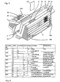
- FIG. 3 is a perspective view of the postage meter from behind.
- the franking machine consists of a meter 1 and a base 2.
- the latter is equipped with a smart card write / read unit 70, which is arranged behind the guide plate 20 and accessible from the housing upper edge 22.
- a chip card 49 is inserted from top to bottom in the insertion slot 72.
- a supplied standing on the edge letter 3, which rests with its surface to be printed on the guide plate is then printed according to the input data with a franking stamp 31.
- the letter feeding opening is bounded laterally by a transparent plate 21 and the guide plate 20.
- the status display of the security module 100 inserted on the motherboard 9 of the meter 1 is visible from the outside through an opening 109.
- the FIG. 4 shows a block diagram of the postal security module PSM 100 in a preferred variant.
- the negative pole of the battery 134 is connected to ground and a pin P23 of the contact group 102.
- the positive pole of the battery 134 is connected to the one input of the voltage changeover switch 180 via the line 193, and the system voltage leading line 191 is connected to the other input of the voltage changeover switch 180.
- the battery 134 is the SL389 / P for a life of up to 3.5 years or the SL-386 / P for a life of up to 6 years with a maximum power consumption by the PSM 100.
- the voltage switch 180 is a commercially available circuit of type ADM 8693ARN.
- the output of the voltage changeover switch 180 is connected via the line 136 to the battery monitoring unit 12 and the detection unit 13.
- the battery monitoring unit 12 and the detection unit 13 communicate with the pins 1, 2, 4 and 5 of the processor 120 via the lines 135, 164 and 137, 139 in communication.
- the output of the voltage switch 180 is also on the line 136 on Supply input of a first memory SRAM, which is the existing battery 134 to nonvolatile memory NVRAM a first technology.
- the security module communicates with the postage meter via the system bus 115, 117, 118.
- the processor 120 may communicate via the system bus and a modem 83 in communication with a remote data center.
- the billing is performed by the ASIC 150 and checked by the processor 120.
- the postal billing data is stored in non-volatile memory of different technology.
- the system voltage is applied to the supply input of a second memory NV-RAM 114.
- the latter is a nonvolatile NVRAM of a second technology, (SHADOWRAM).
- This second technology preferably comprises a RAM and an EEPROM, the latter automatically assuming the data contents in the event of system voltage failure.
- the NVRAM 114 of the second technology is connected to the corresponding address and data inputs of the ASIC 150 via an internal address and data bus 112, 113.
- the ASIC 150 contains at least one hardware abort unit for the calculation of the postal data to be stored.
- Programmable Array Logic (PAL) 160 accommodates access logic to ASIC 150.
- the ASIC 150 is controlled by the PAL 160 logic.
- An address and control bus 117, 115 from the motherboard 9 is connected to corresponding pins of the PAL 160 logic and the PAL 160 generates at least a control signal for the ASIC 150 and a control signal 119 for the program memory FLASH 128.
- the processor 120 executes a program stored in the FLASH 128.
- Processor 120, FLASH 28, ASIC 150, and PAL 160 are interconnected via a module-internal system bus that includes lines 110, 11, 12, 126, 119 for data, address, and control signals.
- the processor 120 of the security module 100 is connected via a module-internal data bus 126 to a FLASH 128 and to the ASIC 150.
- the FLASH 128 is supplied with system voltage Us +. For example, it is a 128 Kbyte FLASH memory type AM29F0I0-45EC.
- the ASIC 150 of the postal security module 100 provides via a module-internal address bus 110, the addresses 0 to 7 to the corresponding address inputs of the FLASH 128.
- the processor 120 of the security module 100 provides via an internal address bus 111 the Addresses 8 to 15 to the corresponding address inputs of the FLASH 128.
- the ASIC 150 of the security module 100 is connected via the contact group 101 of the interface 8 with the data bus 118, with the address bus 117 and the control bus 115 of the motherboard 9 in communication.
- the processor 120 has memory 122, 124 to which an operating voltage Ub + from a voltage monitoring unit 12 is supplied via the line 138.
- a real-time clock RTC 122 and the memory RAM 124 are supplied by an operating voltage via the line 138.
- the voltage monitor unit (Battery Observer) 12 also provides a status signal 164 and responds to a control signal 135.
- the voltage selector 180 as output voltage on the line 136 for the battery observer 12 and memory 116, passes that of its input voltages as a supply voltage which is higher than the other one , Due to the possibility of automatically feeding the described circuit as a function of the magnitude of the voltages Us + and Ub + with the larger of the two, during normal operation the battery 134 can be exchanged without loss of data.
- the battery 134 of the security module 100 feeds in the rest periods outside normal operation in the aforementioned manner the real-time clock (RTC) 122 with date and / or time registers and / or the static RAM (SRAM) 124, which holds security-relevant data. If the voltage of the battery drops below a certain limit during battery operation, the voltage monitoring unit 12 connects the feed point for the RTC and SRAM to ground until reset. The voltage at the RTC and SRAM is then at 0V. As a result, the SRAM 124, which contains eg important cryptographic keys, is deleted very quickly. At the same time, the registers of RTC 122 are cleared and the current time and date are lost.
- RTC real-time clock
- SRAM static RAM
- This action prevents a potential attacker from stopping the postage meter internal clock 122 by manipulating the battery voltage without losing any security related data. This prevents the attacker from circumventing security measures such as long time timers or watchdogs.
- security measures are based on the Figures 9 and 10 explained in detail.
- the RESET unit 130 is connected via the line 131 to the pin 3 of the processor 120 and to a pin of the ASIC 150.
- the processor 120 and the ASIC 150 are reset by a reset generation in the RESET unit 130 when the supply voltage drops.
- the described circuit changes into a self-holding state in which it remains even when subsequently increasing the voltage.
- the processor can query the state of the circuit (status signal) and thus and / or via the evaluation of the contents of the erased memory, conclude that the battery voltage has in the meantime fallen below a certain value.
- the processor may reset the monitor circuit, i. make a fad.
- the unplugged detection unit 13 has to measure the input voltage line 192, which is connected via the plug of the security module and interface 8, preferably via a socket on the motherboard 9 of the postage meter to ground. This measurement is used for static monitoring of the arrangement and forms the basis for monitoring at a first stage. It is contemplated that the unplugged detection unit 13 comprises resettable latching means, the latching being triggered when the voltage level on a sense voltage line 192 deviates from a predetermined potential.
- the evaluation logic includes the processor 120 connected to the other functional units, which is programmed to detect and change the respective state of the security module 100. The state of latching can be queried via the line 139 from the processor 120 of the security module 100.
- the measuring voltage potential on the line 192 corresponds to ground potential when the security module 100 is properly inserted.
- On line 139 is operating voltage potential. Ground voltage potential is present on the line 139 when the security module 100 is unplugged.
- the processor 120 has a fifth pin 5, to which the line 139 is connected in order to query the state of the unplugged detection unit 13, whether it is switched to ground potential with latching. To the state to reset the latching of the unplugged detection unit 13 via the line 137, the processor 120 has a fourth pin 4.
- a current loop 18 is provided which also connects the pins 6 and 7 of the processor 120 via the plug of the security module and via the socket on the motherboard 9 of the postage meter machine.
- the lines on the pins 6 and 7 of the processor 120 are closed only to a current loop 18 at a plugged into the motherboard 9 PSM 100. This loop forms the basis for a dynamic monitoring of the plugged-in safety module on a second level.
- the processor 120 internally comprises a processing unit CPU 121, a real-time clock RTC 122, a RAM unit 124 and an input / output unit 125.
- the processor 120 is equipped with pins 8, 9 for outputting at least one signal for signaling the status of the security module 100 .
- I / O ports of the input / output unit 125 to which module-internal signaling means are connected, for example, colored light emitting diode LED's 107, 108, which signal the state of the security module 100.
- the safety modules can assume different states in their life cycle. So, for example, to detect whether the module contains valid cryptographic keys. Furthermore, it is also important to distinguish whether the module is working or is defective. The exact type and number of module states depends on the implemented functions in the module and on the implementation.
- the unplugged detection unit 13 has a voltage divider, which consists of a series circuit of resistors 1310, 1312, 1314 and between a tapped by a capacitor 1371 supply voltage potential and a Meßwoodspotential on the line 192 is placed.
- the circuit is supplied via line 136 with the system or battery voltage.
- the respective supply voltage from the line 136 passes through a diode 1369 to the capacitor 1371 of the circuit.
- an inverter 1320, 1398 On the output side of the circuit.
- the transistor 1320 of the inverter In the normal state, the transistor 1320 of the inverter is disabled and the supply voltage is via the resistor 1398 on the line 139, which therefore logically '1', ie H level in the normal state leads.
- An L level on line 139 is advantageous as a status signal for unplug because then no current flows into pin 5 of processor 120, increasing battery life.
- the diode 1369 preferably in conjunction with an electrolytic capacitor 1371, ensures that the circuit upstream of the inverter is supplied with a voltage over a relatively long period of time (> 2 sec), in which its function is ensured, even though the voltage on the line 136 is already high was turned off.
- the voltage divider 1310, 1312, 1314 has a tap 1304 to which a capacitor 1306 and the noninverting input of a comparator 1300 are connected.
- the inverting input of the comparator 1300 is connected to a reference voltage source 1302.
- the output of the comparator 1300 is connected on the one hand via the negator 1324.1398 to the line 139 and on the other hand to the control input of a switching means 1322 for latching.
- the switching means 1322 is connected in parallel with the resistor 1310 of the voltage divider, and the latching switching means 1316 is connected between the tap 1304 and ground.
- the tap 1304 of the voltage divider is at the junction of the resistors 1312 and 1314.
- the capacitor 1306 connected between the tap 1304 and ground prevents vibrations.
- the voltage at tap 1304 of the voltage divider is compared in comparator 1300 with the reference voltage of source 1302. If the voltage to be compared at tap 1304 is less than the reference voltage of source 1302, 50, the comparator output remains switched low and transistor 1320 of the inverter is disabled. As a result, the line 139 now receives operating voltage potential and the status signal leads logically '1'.
- the voltage divider is dimensioned so that at ground potential on the line 192, the tap 1304 performs a voltage which is safely below the switching threshold of the comparator 1300.
- the connection is interrupted and the line 192 is no longer connected to ground, because the security module 100 has been detached from the socket on the motherboard 9 or interface unit 8 of the franking machine, the voltage at the tap 1304 is pulled over the voltage of the reference voltage source 1302 and the Comparator 1300 switches over.
- the comparator output is switched to H level, and thus the transistor 1320 is turned on.
- the line 139 is connected to ground potential and the status signal logic '0.
- a transistor 1322 which is connected in parallel with the resistor 1310 of the voltage divider, a self-holding circuit of the unplugged detection unit 13 is realized.
- the control input of transistor 1322 is switched to the H level by the comparator output.
- the transistor 1322 turns on and bridges the resistor 1310.
- the voltage divider is formed only by the resistors 1312 and 1314.
- the switching threshold is increased so much that the comparator remains in the switched state when the line 192 again ground potential, because the security module was plugged again.
- the state of the circuit can be queried via the signal on line 139 from the processor 120.
- the unplugged detection unit 13 as circuit means comprises a line 137 and a latching resetting means 1316, the reset being triggerable by the processor 120 via a signal on the line 137.
- the processor 120 can at any time via a user circuit ASIC 150, via a first contact group 101, via a system bus of the controller 1 and for example via the microprocessor 91 via modem 83 to contact a remote data center, which checks the billing data and optionally other data to the Processor 120 transmitted.
- the user circuit ASIC 150 of the security module 100 is connected to the processor 120 via a module-internal data bus 126.
- the processor 120 may reset the untagged detection unit if reinitialization could be successfully completed using the transmitted data.
- transistor 1316 is turned on via the reset signal on line 137, thus pulling the voltage at tap 1304 below the reference voltage of source 1302 and blocking transistors 1320 and 1322. When transistor 1322 is normally off, resistors 1310 and 1312 in series form the upper part of the above voltage divider and the switching threshold is lowered back to the original state.
- the FIG. 6 shows the mechanical structure of the safety module in side view.
- the security module is designed as a multi-chip module, that is, a plurality of functional units are interconnected on a printed circuit board 106.
- the security module 100 is with a hard potting compound 105 shed, wherein the battery 134 of the security module 100 is disposed outside of the potting compound 105 on a printed circuit board 106 interchangeable.
- it is potted with a potting material 105 that signal means 107, 108 protrude from the potting material at a first location and that the circuit board 106 protrudes laterally with the inserted battery 134 a second location.
- the printed circuit board 106 also has battery contact terminals 103 and 104 for connecting the poles of the battery 134, preferably on the component side above the printed circuit board 106. It is envisaged that for plugging the postal security module PSM 100 on the main board of the meter 1, the contact groups 101 and 102nd are arranged below the circuit board 106 (trace side) of the security module 100.
- the user circuit ASIC 150 is via the first contact group 101 - in a manner not shown - in communication with the system bus of a control device 1 and the second contact group 102 serves to supply the security module 100 with the system voltage.
- the security module is plugged onto the motherboard, then it is preferably arranged within the meter housing in such a way that the signal means 107, 108 near an opening 109 or projects into this.
- the meter housing is thus advantageously designed so that the user can still see the status of the security module from the outside.
- the two light emitting diodes 107 and 108 of the signal means are controlled via two output signals of the I / O ports to the pin 8, 9 of the processor 120. Both LEDs are housed in a common component housing (Bicolorleuchtdiode), which is why the dimensions or the diameter of the opening can remain relatively small and is of the order of the signal means. In principle, three different colors can be displayed (red, green, orange).
- FIG. 7 is a plan view of the postal security module shown.
- FIGS. 8a or 8b show a view of the security module respectively from the right and from the left.
- the location of the contact groups 101 and 102 below the printed circuit board 106 is from the FIGS. 8a and 8b combined with FIG. 6 clear.
- a green LED 107 signals an OK state 220, but a lit LED 108 signals an error state 230 as a result of an at least static self-test.
- the result of such a known self-test can not be falsified because of the direct signaling via the LEDs 107,108.
- the ongoing check in dynamic mode would detect the error and signal the status 240 with orange LED's lit. After switching off / on, booting is required, otherwise no other operation can be performed.
- the case where the installation of a key has been forgotten during manufacture is signaled as state 260, for example with a green blinking LED 107.
- the first functional unit is the processor 120. This constantly evaluates a second daily loan to see whether the latter is exhausted. That's the case where a long time timer has expired.
- the long time timer has expired if the data center has not been contacted for too long, for example to recharge a credit.
- 90 days can be specified by the data center as a time credit and loaded into a memory 124 of the security device during installation or during reloading. At the end of these 90 days, a "LOST" state 250 will be signaled by a flashing red LED.
- the long time timer is preferably a down counter that is implemented in the processor 120.
- state 250 also remains when the security module is disconnected from the meter after the "LOST" state has been reached.
- the suspect state 270 is signaled, preferably a backward counter, also implemented in the processor 120, which constantly evaluates a first daily credit of, say, thirty days to determine whether the latter is exhausted ,
- states 280 and 290 are optionally provided for various further tests.
- further functional units in particular a temperature sensor, may be provided in the security module. If, for example, a temperature was exceeded which could lead to damage in the safety module, then this state 280 can be signaled with the LEDs 107, 108, which light up red and flash orange, and thus produce the overall effect of the alternating red / orange flashing.
- the second functional unit may optionally monitor the battery voltage to see if its capacity has been exhausted.
- a state 290 for a required battery change can be signaled with the LEDs 107, 108, which light up green and flash orange, thus causing the overall effect of the alternating green / orange flashing.
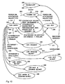
- the FIG. 10 shows a representation of the tests in the system for statically and dynamically changeable states.
- a deactivated system in state 200 after being switched on, transitions via transition Start 201 into state 210, in which a static self-test is performed by the safety module as soon as the operating voltage is present.
- the state 220 with LED 107 is reached in green.
- Transition 203 illustrating such tests returns to state 220 LED green at OK.
- a transition 206 leads to state 240 and the LEDs light orange at an error detected during the dynamic self-test.
- orange flashing LEDs 107, 108 indicate that the connection to the data center is to be included because the security device is already considered suspect.
- the state 210 is reached again.
- the state "LOST" is signaled with the red flashing LED 108.
- state 260 is reached blinking green LED 107.
- optional further transitions may lead either to the further state 280 with red flashing / orange flashing LEDs or state 290 to green flashing / orange flashing LEDs.
- a temperature measurement will result in a need to swap the entire security module. In the latter transition, capacitance measurement of the battery results in a need for battery replacement.
- FIG. 11 shows the mechanical structure of the security module according to a second variant in side view.
- the security module is again designed as a multi-chip module and potted with a hard potting compound 105, wherein the battery 134 of the security module 100 is arranged outside of the potting compound 105 on a printed circuit board 106 interchangeable.
- the potting is performed at a first location with a potting material 105 that the signal means 107, 108 and the inserted battery 134 are mounted externally from the potting material at a second location on the top of the circuit board 106.
- the circuit board 106 has again battery contact terminals 103 and 104 for connecting the poles of the battery 134, preferably on the component side above the circuit board 106.
- the two LEDs 107 and 108 of the signal means are separate components in this variant.
- the two light emitting diodes 107 and 108 of the signal means are controlled via two output signals of the I / O ports to the pin 8, 9 of the processor 120.
- the LEDs can in turn also be controlled in a flashing manner so that different status groups can be distinguished.
- the meter housing is also designed again so that the user can see the status display of the security module from the outside, for example through a viewing window or opening 109. It is also envisaged that for plugging the postal security module PSM 100 on the motherboard of the meter 1 the Contact groups 101 and 102 are arranged below the circuit board 106 of the security module 100.
- a connector 127 includes the contact groups 101 and 102, wherein a connector 127 is disposed on the wiring side of the circuit board 106.
- FIG. 12 is a plan view of the postal security module of the second variant shown.
- the potting compound 105 surrounds the first part of the circuit board 106 in a cuboid, while the second part of the circuit board 106 for the two light emitting diodes 107 and 108, the interchangeably arranged battery 134 and the connector 127 (not visible here) remains free of potting compound.
- the battery contact terminals 103 and 104 are in the FIG. 12 covered by the battery, but as well as the connector 127 in the side view after 13a visible, noticeable.
- the potting of the first part of the circuit board 106 shows neither openings nor elevations and thus offers fewer points of attack for manipulation in criminal intent.
- the potting material 105 is preferably a two-component epoxy resin or polymer or plastic. Suitable is a potting compound from STYCAST®2651-40 FR from EMERSON & CUMING with preferably CATALYST 9 as the second component.
- both components are mixed and applied to both sides of the circuit board 106 in the first part. The latter can be done for example by immersion in the fresh mixture.
- a protective and / or sensor layer which is not visible from the outside after a final external encapsulation, can be attached, which forms a firm connection with the latter during hardening of the encapsulation material 105.
- the potting compound hardens to the solid opaque potting material 105.
- FIGS. 13a or 13b show a view of the security module of the second variant respectively from the right and from the left.
- the position of the connector 127 with the contact groups 101 and 102 below the circuit board 106 is from the Figures 13a and 13b combined with FIG. 12 more visible.
- a connector 127 may be mounted on top of the second part of the circuit board 106, not shown.
- POSTAL SECURITY DEVICE POSTAL SECURITY DEVICE
- the security module or PSD also have a different design, which makes it possible that it can be plugged, for example, on the motherboard of a personal computer that drives a commercial printer as a PC meter.
Description
Die Erfindung betrifft eine Anordnung zum Schutz eines Sicherheitsmoduls, gemäß Anspruch 1. Ein solcher postalischer Sicherheitsmodul ist insbesondere für den Einsatz in einer Frankiermaschine bzw. Postbearbeitungsmaschine oder Computer mit Postbearbeitungsfunktion geeignet.The invention relates to an arrangement for protecting a security module, according to
Moderne Frankiermaschinen, wie die aus der
Für die oben genannte Thermotransfer-Frankiermaschine wurde bereits in
Eine eventuell erforderliche Reparatur einer Frankiermaschine ist dann vor Ort nur schwer möglich, wenn der Zugang zu den Bauteilen erschwert oder eingeschränkt ist. Bei größeren Postverarbeitungsmaschinen oder sogenannten PC-Frankierern wird zukünftig das gesicherte Gehäuse auf das sogenannte postalische Sicherheitsmodul reduziert werden, was die Zugänglichkeit zu den übrigen Bauteilen verbessern kann.Zum wirtschaftlichen Austauschen der Batterie des Sicherheitsmoduls wäre es außerdem wünschenswert, daß sich diese auf relativ einfachem Wege auswechseln läßt. Dazu muß sich die Batterie außerhalb des Sicherheitsbereichs der Frankiermaschine befinden. Wenn die Batterieklemmen aber von außen zugänglich gemacht werden, ist ein möglicher Angreifer in der Lage, die Batteriespannung zu manipulieren. Bekannte batteriegespeiste SRAM und RTC haben bzgl. ihrer geforderten Betriebsspannung unterschiedliche Anforderungen. Die notwendige Spannung zum Halten von Daten von SRAM liegt unterhalb der geforderten Spannung zum Betrieb von RTC. Daß bedeutet, daß ein Verringern der Spannung unter einen bestimmten Grenzwert zu einem unerwünschten Verhalten der Komponenten führt: Die RTC bleibt stehen, die Uhrzeit - gespeichert in SRAM-Zellen - und die Speicherinhalte des SRAM bleiben erhalten. Wenigstens eine der Sicherheitsmaßnahmen, beispielsweise Long Time Watchdogs, wären dann auf der Frankiermaschinenseite unwirksam. Unter Long Time Watchdogs wird folgendes verstanden: Die enifernte Datenzentrale gibt einen Zeitkredit bzw. eine Zeitdauer, insbesondere eine Anzahl von Tagen, oder einen bestimmten Tag vor, bis zu welchem sich die Frankiereinrichtung per Kommunikationsverbindung melden kann. Nach erfolglosen Ablauf des Zeitkredits oder der Frist wird das Frankieren verhindert. Unter dem Titel: Verfahren und Anordnung zur Erzeugung und Überprüfung eines Sicherheitsabdruckes wurde bereits in der
Sicherheitsmodule sind von elektronischen Datenverarbeitungsanlagen her bereits bekannt. Zum Schutz vor Einbruch in eine elektronische Anlage wird in
Eine größere Postverarbeitungsmaschine ist beispielsweise die JetMail®. Ein Frankierdruck wird hier mittels einem stationär angeordneten Tintenstrahldruckkopf bei einem nichtwaagerechten annähernd vertikalen Brieftransport erzeugt. Eine geeignete Ausführung für eine Druckvorrichtung wurde bereits in der
Letzteres wäre nur dann nicht erforderlich, wenn für jedes Poststück einzigartige Abdruke erzeugt werden. Ein geeignetes Verfahren und Anordnung zur Erzeugung und Überprüfung eines Sicherheitsabdruckes ist beispielsweise in den
Weitere Maßnahmen zum Schutz eines Sicherheitsmodul vor einem Angriff auf die in ihm gespeicherten Daten wurden auch in den nicht vorveröffentlichten
Frankiermaschinen sind wie viele andere Produkte ebenfalls modular aufgebaut. Diese Modularität ermöglicht den Austausch von Modulen und Komponenten aus verschiedenen Gründen. So können z.B. defekte Module ausgetauscht und durch überprüfte, reparierte oder neue Module ersetzt werden. Da eine höchste Sorgsamkeit beim Austausch von Baugruppen erforderlich ist, die sicherheitsrelevante Daten enthalten, erfordert der Austausch in der Regel den Einsatz eines Service Technikers und Maßnahmen, die bei unsachgemäßem Gebrauch bzw. unauthorisierten Austausch eines Sicherheitsmoduls dessen Funktionsweise unterbinden. Letzteres ist aber sehr aufwendig.Like many other products, franking machines are also modular. This modularity allows the exchange of modules and components for various reasons. Thus, e.g. defective modules are replaced and replaced by checked, repaired or new modules. Since the utmost care is required in the exchange of assemblies containing safety-relevant data, the replacement usually requires the use of a service technician and measures that prevent its functioning in case of improper use or unauthorized replacement of a security module. The latter is very expensive.
Der Erfindung liegt die Aufgabe zugrunde, mit geringem Aufwand den Schutz vor einem unbefugt manipulierten Sicherheitsmodul zu gewährleisten, wenn das Sicherheitsmodul austauschbar angeordnet ist. Der Austausch soll von jederman auf möglichst einfache Weise möglich sein.The invention has for its object, with little effort to ensure protection against an unauthorized manipulated security module when the security module is arranged interchangeable. The exchange should be possible by anyone in the simplest possible way.
Die Aufgabe wird mit den Merkmalen der Anordnung nach Anspruch 1 gelöst.The object is achieved with the features of the arrangement according to
Die Erfindung geht davon aus, mittels Funktionseinheiten den Austausch, die Manipulation und den Gebrauch eines Sicherheitsmoduls einer Frankiermaschine, Postverarbeitungseinrichtung oder ähnlichen Gerätes festzustellen, um den Benutzern der verschiedenen Geräte eine Gewährleistung über die korrekte Funktionsweise des Sicherheitsmoduls und damit des gesamten Gerätes bieten zu können. Ein Austauschen oder Beschädigen des Sicherheitsmoduls wird mindestens detektiert und ggf. nachträglich als Zustand signalisiert, wenn der Sicherheitsmodul wieder gesteckt ist und mit einer Systemspannung versorgt wird. Die Veränderungen des Zustandes des Sicherheitsmoduls werden mittels einer ersten Funktionseinheit und mittels einer Detektionseinheit erfaßt, welche eine rücksetzbare Selbsthaltung aufweist und von einer Batterie versorgt wird. Die erste Funktionseinheit kann den jeweiligen Zustand auswerten, wenn sie wieder mit Systemspannung versorgt wird. Die Vorteile liegen in einer schnellen Reaktion auf Veränderungen des Zustandes des Sicherheitsmoduls und in einem geringem Batteriestromverbrauch der Detektionseinheit auch während der Nichtversorgung mit der Systemspannung.The invention assumes, by means of functional units, the exchange, the manipulation and the use of a security module of a franking machine, mail processing device or similar device in order to provide users of the various devices with a guarantee about the correct functioning of the security module and thus of the entire device. Exchanging or damaging the safety module is at least detected and, if necessary, subsequently signaled as a state when the safety module is plugged in again and supplied with a system voltage. The changes in the state of the security module are detected by means of a first functional unit and by means of a detection unit, which has a resettable latching and is powered by a battery. The first functional unit can evaluate the respective state when it is supplied with system voltage again. The advantages are a quick response to changes in the state of the security module and a low battery power consumption of the detection unit even during the non-supply of the system voltage.
Eine zweite Funktionseinheit kann die Batteriespannung gegebenenfalls daraufhin überwachen, ob deren Kapazität erschöpft ist. Ein erforderlicher Batteriewechsel wird signalisiert, wobei natürlich eine Versorgung durch die Systemspannung gesichert sein muß. Es ist mindestens dann von einem unsachgemäßem Gebrauch eines Sicherheitsmoduls bei dem Austausch auszugehen, bei welchen nicht nur die Systemspannung fehlt, sondern auch die austauschbar angeordnete Batterie entfernt wird. Damit der Austausch von möglichst gering qualifiziertem Personal und in Zukunft gar durch den Benutzer ausgeführt werden kann, übernimmt die zweite Funktionseinheit die Überwachung auf Spannungsausfall beim Austausch der Batterie, wobei die erste Funktionseinheit erforderlichenfalls zunächst sensitive Daten löscht und damit den weiteren Gebrauch des Sicherheitsmoduls einschränkt oder gar unterbindet. Nach einer vor-Ort-Inspektion des Sicherheitsmoduls durch einen Service, kann bei intaktem Gehäuse, der ursprüngliche Funktionsumfang wiederhergestellt werden. Die erste Funktionseinheit erzwingt bei einer späteren Wiederinbetriebnahme eine Kontaktaufnahme des Sicherheitsmoduls mit einer entfernten Datenzentrale zum Freischalten mindestens einer Funktionseinheit. Falls ohne Batteriewechsel der ganze Sicherheitsmodul ausgetauscht wurde, werden zunächst durch die zweite Funktionseinheit ebenfalls sensitive Daten gelöscht, jedoch können bei der Wiederinbetriebnahme die sensitiven Daten reinitialisiert werden. Zur Kontaktaufnahme sind Verfahren mit einer digitalen oder analogen Übertragungsstrecke einsetzbar. Ebenfalls wird eine Inspektion des Sicherheitsmoduls dann durch einen Service veranlaßt. Das Sicherheitsmodul kann verschiedene Zustände signalisieren. So kann beispielsweise unterschieden werden, ob der letzte Kontakt zur Datenzentrale solange zurückliegt, daß dies bereits verdächtig erscheint oder zulange, daß eine Reinitialisierung nicht mehr gestattet wird. Die erste Funktionseinheit wertet ständig einen ersten Tageskredit aus. Wenn letzterer erschöpft ist, wird der suspekte Zustand signalisiert. Durch Kontaktaufnahme mit der Datenzentrale kann der nor-male Arbeitszustand wiederhergestellt werden, ohne daß eine Inspektion vor Ort durch einen Service erforderlich wird. Der Zeitkredit kann variabel und von Sicherheitsgerät zu Sicherheitsgerät unterschiedlich sein. Der Zeitkredit kann von der Datenzentrale vorgegeben und bei der Installation in einen Speicher des Sicherheitsgerätes geladen werden. Die erste Funktionseinheit wertet ständig einen zweiten Tageskredit aus. Wenn letzterer erschöpft ist, wird der Zustand "LOST" signalisiert. Im letzteren Fall wird ebenfalls eine Inspektion des Sicherheitsmoduls durch einen Service vor Ort erforderlich.A second functional unit may optionally monitor the battery voltage to see if its capacity has been exhausted. A required battery change is signaled, of course, a supply must be backed up by the system voltage. It is to be assumed at least then of an improper use of a security module in the exchange, in which not only the system voltage is missing, but also the interchangeable battery is removed. So that the replacement of the lowest possible qualified personnel and in the future can even be performed by the user, the second functional unit monitors the power failure when replacing the battery, the first functional unit, if necessary, first deletes sensitive data and thus restricts the further use of the security module or even prevented. After an on-site inspection of the security module by a service, the original functionality can be restored with the housing intact. The first functional unit enforces a later re-commissioning contact the security module with a remote data center to unlock at least one functional unit. If the entire security module has been exchanged without changing the battery, sensitive data is also first deleted by the second functional unit, but the sensitive data can be reinitialized during the restart. To establish contact methods with a digital or analog transmission link can be used. Also, an inspection of the security module is then by a Service causes. The safety module can signal different states. For example, a distinction can be made as to whether the last contact with the data center was made so long ago that it already seems suspicious or long that reinitialization is no longer permitted. The first functional unit is constantly evaluating a first day loan. When the latter is exhausted, the suspicious state is signaled. By contacting the data center, the normal working condition can be restored without requiring an on-site inspection by a service. The time credit can be variable and vary from security device to security device. The time credit can be specified by the data center and loaded during installation into a memory of the security device. The first functional unit constantly evaluates a second daily loan. When the latter is exhausted, the state "LOST" is signaled. In the latter case, an inspection of the security module by a local service is also required.
Die Anordnung zum Schutz des Sicherheitsmoduls umfaßt das Sicherheitsmodul, mit einer Logik mit Mitteln zur Versorgung des Sicherheitsmoduls mit einer Systemspannung oder mit einer Spannung aus einer Batterie und mit einer Anzahl an Überwachungsmitteln. Sie wird beschrieben durch mindestens eine erste und zweite Funktionseinheit sowie durch Mittel zum Laden mindestens eines von der Datenzentrale vorgegebenen Zeitkredits und durch ein Signalmittel, welches mit einer ersten Funktionseinheit verbunden ist, wobei das Laden bei der Installation und beim Nachladen in einen Speicher des Sicherheitsgerätes vorgenommen wird, und wobei die erste Funktionseinheit einen Tageskredit auf Zeitablauf auswertet und das Signalmittel ansteuert, mindestens um den Zeitablauf zu signalisieren, sowie durch Mittel der zweiten Funktionseinheit zum Löschen von sensitiven Daten im Speicher aufgrund eines unsachgemäßen Gebrauchs oder Austausches des Sicherheitsmoduls.The security module protection assembly comprises the security module having logic means for supplying the security module with a system voltage or with a voltage from a battery and with a number of monitoring means. It is described by at least a first and a second functional unit and by means for loading at least one time credit specified by the data center and by a signal means connected to a first functional unit, the charging being performed during installation and reloading into a memory of the security device is, and wherein the first functional unit evaluates a day loan on time and the signal means controls, at least to signal the timing, and by means of the second functional unit for deleting sensitive data in memory due improper use or replacement of the security module.
Vorteilhafte Weiterbildungen der Erfindung sind in den Unteransprüchen gekennzeichnet bzw. werden nachstehend zusammen mit der Beschreibung der bevorzugten Ausführung der Erfindung anhand der Figuren näher dargestellt. Es zeigen:
-
Figur 1 -
Figur 2 -
Figur 3 -
Figur 4 -
Figur 5 -
Figur 6 -
Figur 7 -
Figur 8a , Ansicht des Sicherheitsmoduls von rechts (1 .Variante), -
Figur 8b , Ansicht des Sicherheitsmoduls von links (1 .Variante), -
Figur 9 -
Figur 10 -
Figur 11 -
Figur 12 -
Figur 13a , Ansicht des Sicherheitsmoduls von rechts (2.Variante), -
Figur 13b , Ansicht des Sicherheitsmoduls von links (2.Variante).
-
FIG. 1 , Block diagram and interface of the security module, -
FIG. 2 , Block diagram of the franking machine, -
FIG. 3 , Perspective view of the franking machine from behind, -
FIG. 4 , Block diagram of the security module (second variant), -
FIG. 5 , Circuit diagram of the detection unit, -
FIG. 6 , Side view of the security module (1st variant), -
FIG. 7 , Top view of the security module (1st variant), -
FIG. 8a , View of the security module from the right (1st variant), -
FIG. 8b , View of the safety module from the left (1st variant), -
FIG. 9 , Table for status signaling, -
FIG. 10 , Representation of the tests in the system for static and dynamically changeable states, -
FIG. 11 , Side view of the security module (2nd variant), -
FIG. 12 , Top view of the security module (2nd variant), -
FIG. 13a , View of the security module from the right (2nd variant), -
FIG. 13b , View of the safety module from the left (2nd variant).
In der
Das Sicherheitsmodul 100 weist in an sich bekannter Weise einen Mikroprozessor 120 auf, der einen - nicht gezeigten - integrierten Festwertspeicher (internal ROM) mit dem speziellen Anwendungsprogramm enthält, was für die Frankiermaschine von der Postbehörde bzw. vom jeweiligen Postbeförderer zugelassen ist. Alternativ kann an den internen Datenbus 126 ein üblicher Festwertspeicher ROM oder FLASHSpeicher angeschlossen werden.
Das Sicherheitsmodul 100 weist in an sich bekannter Weise eine ResetSchaltungseinheit 130, einen Anwenderschaltkreis ASIC 150 und eine Logik PAL 160 auf, die für den ASIC als Steuersignalgenerator dient. Die Reset-Schaltungseinheit 130 bzw. der Anwenderschaltkreis ASIC 150 und die Logik PAL 160 sowie eventuell weitere - nicht gezeigte - Speicher werden über die Leitungen 191 bzw. 129 mit Systemspannung Us+ versorgt, welche bei eingeschalteter Frankiereinrichtung von der Hauptplatine 9 geliefert wird. In der
The
The
Die Systemspannung Us+ liegt außerdem über eine Diode 181 und die Leitung 136 am Eingang der Spannungsüberwachungseinheit 12 an. Am Ausgang der Spannungsüberwachungseinheit 12 wird eine zweite Betriebsspannung Ub+ geliefert, welche über die Leitung 138 zur Verfügung steht. Bei ausgeschalteter Frankiereinrichtung steht nicht die Systemspannung Us+, sondern nur die Batteriespannung Ub+ zur Verfügung. Die am negativen Pol liegende Batteriekontaktklemme 104 ist mit Masse verbunden. Von der am positiven Pol liegenden Batteriekontaktklemme 103 wird Batteriespannung über eine Leitung 193, über eine zweite Diode 182 und die Leitung 136 an den Eingang der Spannungsüberwachungseinheit geliefert. Alternativ zu den beiden Dioden 181, 182 kann ein handelsüblicher Schaltkreis als Spannungsumschalter 180 eingesetzt werden.The system voltage Us + is also applied via a
Der Ausgang der Spannungsüberwachungseinheit 12 ist über eine Leitung 138 mit einem Eingang für diese zweite Betriebsspannung Ub+ des Prozessors 120 verbunden, welcher mindestens auf einen RAMSpeicherbereich 122, 124 führt und dort eine nichtflüchtige Speicherung solange garantiert, wie die zweite Betriebsspannung Ub+ in der erforderlichen Höhe anliegt. Der Prozessor 120 enthält vorzugsweise einen internen RAM 124 und eine Echtzeituhr (RTC) 122.The output of the
Die Spannungsüberwachungseinheit 12 im Sicherheitsmodul weist eine rücksetzbare Selbsthaltung auf, die vom Prozessor 120 über eine Leitung 164 abgefragt und über eine Leitung 135 zurückgesetzt werden kann. Für eine Rücksetzung der Selbsthaltung weist die Spannungsüberwachungseinheit 12 Schaltungsmittel auf. Die Rücksetzung ist erst auslösbar, wenn die Batteriespannung über die vorbestimmte Schwelle angestiegen ist. Die Leitungen 135 and 164 sind je mit einem Pin (Pin1 und 2) des Prozessors 120 verbunden. Die Leitung 164 liefert ein Statussignal an den Prozessor 120 und die Leitung 135 liefert ein Steuersignal an die Spannungsüberwachungseinheit 12.The
Die Leitung 136 am Eingang der Spannungsüberwachungseinheit 12 versorgt zugleich eine Ungestecktsein-Detektionseinheit 13 mit Betriebsoder Batteriespannung. Die Ungestecktsein-Detektionseinheit 13 gibt auf der Leitung 139 ein Statussignal an einen Pin 5 des Prozessors 120 ab, das eine Aussage über den Zustand der Schaltung gibt. Vom Prozessor 120 wird der Zustand der Ungestecktsein-Detektionseinheit 13 über die Leitung 139 abgefragt. Der Prozessor kann mit einem vom Pin 4 des Prozessors 120 über die Leitung 137 abgegebenen Signal die Ungestecktsein-Detektionseinheit 13 zurücksetzen. Nach dem Setzen wird eine statische Prüfung auf Anschluß durchgeführt. Dazu wird über eine Leitung 192 Massepotential abgefragt, welches am Anschluß P4 des interfaces 8 des postalischen Sicherheitsmoduls PSM 100 anliegt und nur abfragbar ist, wenn der Sicherheitsmodul 100 ordnungsgemäß gesteckt ist. Bei gesteckten Sicherheitsmodul 100 wird Massepotential des negativen Pols 104 der Batterie 134 des postalischen Sicherheitsmoduls PSM 100 auf den Anschluß P23 des Interfaces 8 gelegt und ist somit am Anschluß P4 des Interfaces 8 über die Leitung 192 von der Ungestecktsein-Detektionseinheit 13 abfragbar.The
An den Pins 6 und 7 des Prozessors 120 liegt eine Leitungsschleife, welche über die Pins P1 und P2 der Kontaktgruppe 102 des Interfaces 8 zum Prozessor 120 zurückgeschleift wird. Zur dynamischen Prüfung des Angeschlossenseins des postalischen Sicherheitsmoduls PSM 100 an der Hauptplatine 9 werden vom Prozessor 120 wechselnde Signalpegel in ganz unregelmäßigen Zeitabständen an die Pin's 6, 7 angelegt und über die Schleife zurückgeschleift.
Das postalische Sicherheitsmodul PSM 100 ist mit einer Long-LiveBatterie bestückt, welches auch eine Überwachung des Gebrauchs ermöglicht, ohne das das Sicherheitsmodul an einer Systemspannung eines Postverabeitungseinrichtung liegt. Der sachgemäße Gebrauch, Betrieb, Installation oder Einbau in der geeigneten Umgebung sind solche von den Funktionseinheiten des Sicherheitsmoduls zu prüfende Eigenschaften. Eine Erstinstallation wird vom Hersteller des postalischen Sicherheitsmoduls vorgenommen. Es ist also nach dieser Erstinstallation zunächst lediglich zu prüfen, ob das postalische Sicherheitsmodul von ihrem Einsatzfeld (Postverabeitungseinrichtung) getrennt wird, wobei dies in der Regel bei einem Austausch erfolgt.
Die Überwachung dieses Zustandes wird von der UngestecktseinDetektionseinheit 13 vorgenommen. Hierbei wird über die Masseverbindung am Pin 4 der interfaceeinheit 8 ein Spannungspegel überwacht. Beim Austausch der Funktionseinheit wird diese Masseverbindung unterbrochen und die Ungestecktsein-Detektionseinheit 13 registriert diesen Vorgang als Information. Da bei einem mechanischen oder chemischen Angriff auf das Sicherheitsmodul 100 und für jede Trennung des Sicherheitsmoduls 100 von der Interfaceeinheit 8, die Speicherung dieser Information durch den speziellen batteriegetriebenen Schaltungsaufbau gewährleistet ist, kann eine Auswertung dieser Information zu jeder Zeit erfolgen, falls eine Wiederinbetriebnahme gewünscht ist. Die regelmäßige Auswertung dieses Trennungs- bzw. Ungestecktsein-Signals auf der Leitung 139 der Detektionseinheit 13 ermöglicht es dem Prozessor 120 sensitive Daten zu löschen, ohne jedoch damit die Abrechnungs- und Kundendaten in den NVRAM-Speichern zu verändern. Der momentane Zustand des postalischen Sicherheitsmoduls mit den gelöschten sensitiven Daten kann als Wartungszustand aufgefaßt werden, in welchem in der Regel der Austausch, eine Reparatur oder sonstiges vorgenommen wird. Da die sensitiven Daten der Funktionseinheit gelöscht sind, ist ein Fehler aufgrund einer unsachgemäßen Handhabung des postalischen Sicherheitsmoduls ausgeschlossen. Die sensitiven Daten sind beispielsweise kryptographische Schlüssel. Der Prozessor 120 verhindert im Wartungszustand eine Kernfunktionalität des postalischen Sicherheitsmoduls, welche beispielweise in der Abrechnung und/oder Berechnung eines Sicherheitscodes für die Sicherheitsmarkierung in einem Sicherheitsabdruck besteht.At the
The postal
The monitoring of this condition is performed by the
Zur Wiederinbetriebnahme wird das postalische Sicherheitsmodul PSM zunächst gesteckt und elektrisch mit der entsprechenden Interfaceeinheit 8 eines Postbearbeitungsgerätes verbunden. Anschließend wird das Gerät eingeschaltet und somit das postalische Sicherheitsmodul wieder mit Systemspannung Us+ versorgt. Aufgrund des speziellen Zustandes muß nun der sachgemäße Einbau des postalischen Sicherheitsmoduls durch ihre Funktionseinheit erneut geprüft werden. Hierfür wird eine zweite Stufe einer Prüfung (dynamische Gestecktsein-Detektion) vorgesehen. Über eine zwischen der ersten Funktionseinheit (Prozessor 120) und der Stromschleife 18 der Interfaceeinheit 8 hergestellten operative Verbindung werden Informationen ausgetauscht, deren fehlerfreie Übermittlung den Beweis für den sachgemäßen Einbau erbringt. Dies ist Voraussetzung für eine erfolgreiche Wiederinbetriebnahme.For recommissioning the postal security module PSM is first inserted and electrically connected to the corresponding
Für den Zustandswechsel in den normalen Betriebszustand ist nun noch eine Reinitialisierung der sensitiven Daten erforderlich. Zwischen dem postalischen Sicherheitsmodul und einer dritten Instanz wird eine Kommunikation vorgenommen, wobei letztere diese sensitiven Daten übermittelt. Nach erfolgreicher Übermittlung wird die UngestecktseinDetektionseinheit 13 zurückgesetzt und das postalische Sicherheitsmodul nimmt wieder seinen normalen Betriebszustand ein. Die Wiederinbetriebnahme ist abgeschlossen.For the state change to the normal operating state, a reinitialization of the sensitive data is now required. Between the postal security module and a third instance, a communication is made, the latter transmits these sensitive data. Upon successful transmission, the
Die
Der Programmspeicher 92 enthält ein Betriebsprogramm mindestens zum Drucken und wenigstens sicherheitsrelevante Bestandteile des Programms für eine vorbestimmte Format-Änderung eines Teils der Nutzdaten.
Der Arbeitsspeicher RAM 93 dient zur flüchtigen Zwischenspeicherung von Zwischenergebnissen. Der nichtflüchtige Speicher NVM 94 dient zur nichtflüchtigen Zwischenspeicherung von Daten, beispielsweise von statistischen Daten, die nach Kostenstellen geordnet sind. Der Kalender/Uhrenbaustein 95 enthält ebenfalls adressierbare aber nichtflüchtige Speicherbereiche zur nichtflüchtigen Zwischenspeicherung von Zwischenergebnissen oder auch bekannten Programmteilen (beispielsweise für den DES-Algorithmus). Es ist vorgesehen, daß die Steuereinrichtung 1 mit der Chipkarten-Schreib/Leseeinheit 70 verbunden ist, wobei der Mikroprozessor 91 der Steuereinrichtung 1 beispielsweise dazu programmiert ist, die Nutzdaten N aus dem Speicherbereich einer Chipkarte 49 zu deren Anwendung in entsprechende Speicherbereiche der Frankiermaschine zu laden. Eine in einen Einsteckschlitz 72 der Chipkarten-Schreib/Leseeinheit 70 eingesteckte erste Chipkarte 49 gestattet ein Nachladen eines Datensatzes in die Frankiermaschine für mindestens eine Anwendung. Die Chipkarte 49 enthält beispielsweise die Portogebühren für alle üblichen Postbefördererleistungen entsprechend des Tarifs der Postbehörde und ein Postbefördererkennzeichen, um mit der Frankiermaschine ein Stempelbild zugenerieren und entsprechend des Tarifs der Postbehörde die Poststücke freizustempeln.The
The
Die Steuereinrichtung 1 bildet das eigentliche Meter mit den Mitteln 91 bis 95 der vorgenannten Hauptplatine 9 und umfaßt auch eine Tastatur 88, eine Anzeigeeinheit 89 sowie einen anwendungsspezifischen Schaltkreis ASIC 90 und das Interface 8 für das postalische Sicherheitsmodul PSM 100. Das Sicherheitsmodul PSM 100 ist über einen Steuerbus mit dem vorgenannten ASIC 90 und dem Mikroprozessor 91 sowie über den parallelen µC-Bus mindestens mit den Mitteln 91 bis 95 der Hauptplatine 9 und der mit Anzeigeeinheit 89 verbunden. Der Steuerbus führt Leitungen für die Signale CE, RD und WR zwischen dem Sicherheits-modul PSM 100 und dem vorgenannten ASIC 90. Der Mikroprozessor 91 weist vorzugsweise einen Pin für ein vom Sicherheitsmodul PSM 100 abgegebenes Interruptsignal i, weitere Anschlüsse für die Tastatur 88, eine serielle Schnittstelle SI-1 für den Anschluß der ChipkartenSchreib/Lese-Einheit 70 und eine serielle Schnittstelle SI-2 für den optionalen Anschluß eines MODEMs auf Mittels des MODEMs kann beispielsweise das im nichtflüchtigen Speicher des postalischen Sicherheitsmittels PSM 100 gespeicherte Guthaben erhöht werden.The
Das postalische Sicherheitsmittel PSM 100 wird von einem gesicherten Gehäuse umschlossen. Vor jedem Frankierabdruck wird im postalischen Sicherheitsmodul PSM 100 eine hardwaremäßige Abrechnung durchgeführt. Die Abrechnung erfolgt unabhängig von Kostenstellen. Das postalische Sicherheitsmittel PSM 100 kann intern so ausgeführt sein, wie in der europäischen Anmeldung
Die Schnittstellenschaltung 96 gekoppelt mit der in der Maschinenbasis befindlichen Schnittstellenschaltung 14 stellt mindestens eine Verbindung zu den Sensoren 6, 7, 17 und zu den Aktoren, beispielsweise zum Antriebsmotor 15 für die Walze 11 und zu einer Reinigungs- und Dichtstation RDS 40 für den Tintenstrahldruckkopf 4, sowie zum Labelgeber 50 in der Maschinenbasis her Die prinzipielle Anordnung und das Zusammenspiel zwischen Tintenstrahldruckkopf 4 und der RDS 40 sind der
Einer der in der Führungsplatte 20 angeordneten Sensoren 7, 17 ist der Sensor 17 und dient zur Vorbereitung der Druckauslösung beim Brieftransport. Der Sensor 7 dient zur Briefanfangserkennung zwecks Druckauslösung beim Brieftransport. Die Transporteinrichtung besteht aus einem Transportband 10 und zwei Walzen 11,11'. Eine der Walzen ist die mit einem Motor 15 ausgestattete Antriebswalze 11, eine andere ist die mitlaufende Spannwalze 11'. Vorzugsweise ist die Antriebswalze 11 als Zahnwalze ausgeführt, entsprechend ist auch das Transportband 10 als Zahnriemen ausgeführt, was die eindeutige Kraftübertragung sichert. Ein Encoder 5, 6 ist mit einer der Walzen 11, 11' gekoppelt. Vorzugsweise sitzt die Antriebswalze 11 mit einem Inkrementalgeber 5 fest auf einer Achse. Der Inkrementalgeber 5 ist beispielsweise als Schlitzscheibe ausgeführt, die mit einer Lichtschranke 6 zusammen wirkt, und gibt über die Leitung 19 ein Encodersignal an die Hauptplatine 9 ab.
Es ist vorgesehen, daß die einzelnen Druckelemente des Druckkopfes innerhalb seines Gehäuses mit einer Druckkopfelektronik verbunden sind und daß der Druckkopf für einen rein elektronischen Druck ansteuerbar ist. Die Drucksteuerung erfolgt auf Basis der Wegsteuerung, wobei der gewählte Stempelversatz berücksichtigt wird, welcher per Tastatur 88 oder bei Bedarf per Chipkarte eingegeben und im Speicher NVM 94 nichtflüchtig gespeichert wird. Ein geplanter Abdruck ergibt sich somit aus Stempelversatz (ohne Drucken), dem Frankierdruckbild und gegebenfalls weiteren Druckbildern für Werbeklischee, Versandinformationen (Wahldrucke) und zusätzlichen editierbaren Mitteilungen. Der nichtflüchtige Speicher NVM 94 weist eine Vielzahl an Speicherbereichen auf. Darunter sind solche, welche die geladenen Portogebührentabellen nichtflüchtig speichern.
Die Chipkarten-Schreib/Leseeinheit 70 besteht aus einem zugehörigen mechanischen Träger für die Mikroprozessorkarte und Kontaktiereinheit 74. Letztere gestattet eine sichere mechanische Halterung der Chipkarte in Lese-Position und eindeutige Signalisierung des Erreichens der Leseposition der Chipkarte in der Kontaktierungseinheit. Die Mikroprozessorkarte mit dem Mikroprozessor 75 besitzt eine einprogrammierte Lesefähigkeit für alle Arten von Speicherkarten bzw. Chipkarten. Das Interface zur Frankiermaschine ist eine serielle Schnittstelle gemäß RS232-Standard. Die Datenübertragungsrate beträgt min. 1,2 K Baud. Das Einschalten der Stromversorgung erfolgt mittels einem an der Hauptplatine angeschlossenen Schalter 71. Nach Einschalten der Stromversorgung erfolgt eine Selbsttestfunktion mit Bereitschaftsmeldung.The
One of the arranged in the
It is envisaged that the individual printing elements of the print head are connected within its housing with a print head electronics and that the print head for a purely electronic pressure can be controlled. The pressure control is based on the path control, whereby the selected stamp offset is taken into account, which is entered by
The smart card write /
In der
Die
Das Sicherheitsmodul steht mit der Frankiermaschine über den Systembus 115,117, 118 in Verbindung. Der Prozessor 120 kann über den Systembus und ein Modem 83 in Kommunikationsverbindung mit einer entfernten Datenzentrale eintreten. Die Abrechnung wird vom ASIC 150 vollzogen und vom Prozessor 120 überprüft. Die postalischen Abrechnungsdaten werden in nichtflüchtigen Speichern unterschiedlicher Technologie gespeichert.
Die Systemspannung liegt am Versorgungseingang eines zweiten Speichers NV-RAM 114 an. Bei letzterem handelt es sich um einen nichtflüchtigen Speicher NVRAM einer zweiten Technologie, (SHADOWRAM). Diese zweiten Technologie umfaßt vorzugsweise ein RAM und ein EEPROM, wobei letzteres die Dateninhalte bei Systemspannungsausfall automatisch übernimmt. Der NVRAM 114 der zweiten Technologie ist mit den entsprechenden Adress- und Dateneingängen des ASIC's 150 über einen internen Adreß- und Datenbus 112, 113 verbunden.The
The security module communicates with the postage meter via the
The system voltage is applied to the supply input of a second memory NV-
Der ASIC 150 enthält mindestens eine Hardware-Abrecheneinheit für die Berechnung der zu speichernden postalischen Daten. In der Programmable Array Logic (PAL) 160 ist eine Zugriffslogik auf den ASIC 150 untergebracht. Der ASIC 150 wird durch die Logik PAL 160 gesteuert. Ein Adreß- und Steuerbus 117, 115 von der Hauptplatine 9 ist an entsprechenden Pins der Logik PAL 160 angeschlossen und die PAL 160 erzeugt mindestens ein Steuersignal für das ASIC 150 und ein Steuersignal 119 für den Programmspeicher FLASH 128. Der Prozessor 120 arbeitet ein Programm ab, das im FLASH 128 gespeichert ist. Der Prozessor 120, FLASH 28, ASIC 150 und PAL 160 sind über einen modulinternen Systembus miteinander verbunden, der Leitungen 110,111,126,119 für Daten-, Adreß- und Steuersignale enthält.
Der Prozessor 120 des Sicherheitsmoduls 100 ist über einen modulinternen Datenbus 126 mit einem FLASH 128 und mit dem ASIC 150 verbunden. Der FLASH 128 wird mit Systemspannung Us+ versorgt. Er ist beispielsweise ein 128 Kbyte- FLASH-Speicher vom Typ AM29F0I0-45EC. Der ASIC 150 des postalischen Sicherheitsmoduls 100 liefert über einen modulinternen Adreßbus 110 die Adressen 0 bis 7 an die entsprechenden Adreßeingänge des FLASH 128. Der Prozessor 120 des Sicherheitsmoduls 100 liefert über einen internen Adreßbus 111 die Adressen 8 bis 15 an die entsprechenden Adresseingänge des FLASH 128. Der ASIC 150 des Sicherheitsmoduls 100 steht über die Kontaktgruppe 101 des Interfaces 8 mit dem Datenbus 118, mit dem Adreßbus 117 und dem Steuerbus 115 der Hauptplatine 9 in Kommunikationsverbindung.The
The
Es ist vorgesehen, daß der Prozessor 120 Speicher 122, 124 aufweist, an welche über die Leitung 138 eine Betriebsspannung Ub+ von einer Spannungsüberwachungseinheit 12 zugeführt wird. Insbesondere eine Echtzeituhr RTC 122 und der Speicher RAM 124 werden von einer Betriebsspannung über die Leitung 138 versorgt. Die Spannungsüberwachungseinheit (Battery Observer) 12 liefert außerdem ein Statussignal 164 und reagiert auf ein Steuersignal 135. Der Spannungsumschalter 180 gibt als Ausgangsspannung auf der Leitung 136 für den Battery Observer 12 und Speicher 116 diejenige seiner Eingangsspannungen als Versorgungsspannung weiter, die größer als die andere ist. Durch die Möglichkeit, die beschriebene Schaltung in Abhängigkeit von der Höhe der Spannungen Us+ und Ub+ automatisch mit der größeren von beiden zu speisen, kann während des Normalbetriebs die Batterie 134 ohne Datenverlust gewechselt werden.It is envisaged that the
Die Batterie 134 des Sicherheitsmoduls 100 speist in den Ruhezeiten außerhalb des Normalbetriebes in vorerwähnter Weise die Echtzeituhr (RTC) 122 mit Datums und/oder Uhrzeitregistern und/oder den statischen RAM (SRAM) 124, der sicherheitsrelevante Daten hält. Sinkt die Spannung der Batterie während des Batteriebetriebs unter eine bestimmte Grenze, so wird von der Spannungsüberwachungseinheit 12 der Speisepunkt für die RTC und SRAM bis zum Rücksetzen mit Masse verbunden. Die Spannung an der RTC und am SRAM liegt dann bei 0V. Das führt dazu, daß der SRAM 124, der z.B. wichtige kryptografische Schlüssel enthält, sehr schnell gelöscht wird. Gleichzeitig werden auch die Register der RTC 122 gelöscht und die aktuelle Uhrzeit und das aktuelle Datum gehen verloren. Durch diese Aktion wird verhindert, daß ein möglicher Angreifer durch Manipulation der Batteriespannung die frankiermaschineninterne Uhr 122 anhält, ohne daß sicherheitsrelevante Daten verloren gehen. Somit wird verhindert, daß der Angreifer Sicherheitsmaßnahmen, wie beispielsweise Long Time Timer oder Watchdogs umgeht. Die vorgenannten Sicherheitsmaßnahmen werden anhand der
Die RESET-Einheit 130 ist über die Leitung 131 mit dem Pin 3 des Prozessors 120 und mit einem Pin des ASIC's 150 verbunden. Der Prozessor 120 und das ASIC 150 werden bei Absinken der Versorgungsspannung durch eine Resetgenerierung in der RESET-Einheit 130 zurückgesetzt.The
Gleichzeitig mit der Indikation der Unterspannung der Batterie wechselt die beschriebene Schaltung in einen Selbsthaltezustand, in dem sie auch bei nachträglicher Erhöhung der Spannung bleibt. Beim nächsten Einschalten des Moduls kann der Prozessor den Zustand der Schaltung abfragen (Statussignal) und damit und/oder über die Auswertung der Inhalte des gelöschten Speichers darauf schließen, daß die Batteriespannung zwischenzeitlich einen bestimmten Wert unterschritten hat. Der Prozessor kann die Überwachungsschaltung zurücksetzen, d.h. "schart" machen.Simultaneously with the indication of the undervoltage of the battery, the described circuit changes into a self-holding state in which it remains even when subsequently increasing the voltage. The next time the module is switched on, the processor can query the state of the circuit (status signal) and thus and / or via the evaluation of the contents of the erased memory, conclude that the battery voltage has in the meantime fallen below a certain value. The processor may reset the monitor circuit, i. make a fad.
Die Ungestecktsein-Detektionseinheit 13 hat zur Messung der Eingangsspannung eine Leitung 192, die über den Stecker des Sicherheitsmoduls und Interface 8, vorzugsweise über einen Sockel auf der Mutterplatine 9 der Frankiermaschine mit Masse verbunden ist. Diese Messung dient zur statischen Überwachung des Gesteckseins und bildet die Grundlage für eine Überwachung auf einer ersten Stufe. Es ist vorgesehen, daß die Ungestecktsein-Detektionseinheit 13 Schaltungsmittel für eine rücksetzbare Selbsthaltung aufweist, wobei die Selbsthaltung ausgelöst wird, wenn der Spannungspegel auf einer Meßspannungsleitung 192 von einem vorbestimmten Potential abweicht. Zugleich umfaßt die AuswerteLogik den mit den anderen Funktionseinheiten verbundenen Prozessor 120, welcher programmiert ist, den jeweiligen Zustand des Sicherheitsmoduls 100 festzustellen und zu verändern. Der Zustand der Selbsthaltung ist über die Leitung 139 vom Prozessor 120 des Sicherheitsmoduls 100 abfragbar. Das Meßspannungspotential auf der Leitung 192 entspricht Massepotential, wenn der Sicherheitsmodul 100 ordnungsgemäß gesteckt ist. Auf der Leitung 139 liegt Betriebsspannungspotential. Massespannungspotential liegt auf der Leitung 139 an, wenn der Sicherheitsmodul 100 ungesteckt ist. Der Prozessor 120 weist einen fünften Pin5 auf, an welchem die Leitung 139 angeschlossen ist, um den Zustand der Ungestecktsein-Detektionseinheit 13 abzufragen, ob sie auf Massepotential mit Selbsthaltung geschaltet ist. Um den Zustand der Selbsthaltung der Ungestecktsein-Detektionseinheit 13 über die Leitung 137 zurückzusetzen, weist der Prozessor 120 einen vierten Pin 4 auf.The
Weiterhin ist eine Stromschleife 18 vorgesehen, die die Pins 6 und 7 des Prozessors 120 ebenfalls über den Stecker des Sicherheitsmoduls und über den Sockel auf der Hauptplatine 9 der Frankiermaschine miteinander verbindet. Die Leitungen an den Pins 6 und 7 des Prozessors 120 sind nur bei einem an die Hauptplatine 9 gesteckten PSM 100 zu einer Stromschleife 18 geschlossen. Diese Schleife bildet die Grundlage für eine dynamische Überwachung des Angestecktseins des Sicherheitsmoduls auf einer zweiten Stufe.Furthermore, a
Der Prozessor 120 weist intern eine Verarbeitungseinheit CPU 121, eine Echtzeituhr RTC 122 eine RAM-Einheit 124 und eine Ein/Ausgabe-Einheit 125 auf Der Prozessor 120 ist mit Pin's 8, 9 zur Ausgabe mindestens eines Signals zur Signalisierung des Zustandes des Sicherheitsmoduls 100 ausgestattet. An den Pins 8 und 9 liegen I/O-Ports der Ein/AusgabeEinheit 125, an welchen modulinterne Signalmittel angeschlossen sind, beispielsweise farbige Lichtemitterdioden LED's 107, 108, welche den Zustand des Sicherheitsmoduls 100 signalisieren. Die Sicherheitsmodule können in ihrem Lebenszyklus verschiedene Zustände einnehmen. So muß z.B. detektiert werden, ob das Modul gültige kryptografische Schlüssel enthält. Weiterhin ist es auch wichtig zu unterscheiden, ob das Modul funktioniert oder defekt ist. Die genaue Art und Anzahl der Modulzustände ist von den realisierten Funktionen im Modul und von der Implementierung abhängig.The
Anhand der
Der Spannungsteiler 1310, 1312, 1314 weist einen Abgrift 1304 auf, an welchem ein Kondensator 1306 und der nichtinvertierende Eingang eines Komparators 1300 angeschlossen sind. Der invertierende Eingang des Komparators 1300 ist mit einer Referenzspannungsquelle 1302 verbunden. Der Ausgang des Komparators 1300 ist einerseits über den Negator 1324,1398 mit der Leitung 139 und andererseits mit dem Steuereingang eines Schaltmittels 1322 für die Selbsthaltung verbunden. Das Schaltmittel 1322 ist zum Widerstand 1310 des Spannungsteilers parallel geschaltet und das Schaltmittel 1316 für eine Rücksetzung der Selbsthaltung ist zwischen dem Abgriff 1304 und Masse geschaltet. Der Abgriff 1304 des Spannungsteilers liegt am Verbindungspunkt der Widerstande 1312 und 1314. Der zwischen dem Abgriff 1304 und Masse geschaltete Kondensator 1306 verhindert Schwingungen. Die Spannung am Abgriff 1304 des Spannungsteilers wird im Komparator 1300 mit der Referenzspannung der Quelle 1302 verglichen. Ist die zu vergleichende Spannung am Abgriff 1304 kleiner als die Referenzspannung der Quelle 1302, 50 bleibt der Komparatorausgang auf L-Pegel geschaltet und der Transistor 1320 des Negators ist gesperrt. Dadurch erhält die Leitung 139 nun Betriebsspannungspotential und das Statussignal führt logisch '1'. Der Spannungsteiler ist so dimensioniert, daß bei Massepotential auf der Leitung 192 der Abgriff 1304 eine Spannung führt, welche sicher unterhalb der Schaltschwelle des Komparators 1300 liegt. Wird die Verbindung unterbrochen und die Leitung 192 ist nicht mehr mit Masse verbunden, weil das Sicherheitsmodul 100 vom Sockel auf der Hauptplatine 9 bzw. Interfaceeinheit 8 der Frankiermaschine gelöst wurde, so wird die Spannung am Abgriff 1304 über die Spannung der Referenzspannungsquelle 1302 gezogen und der Komparator 1300 schaltet um. Der Komparatorausgang wird auf H-Pegel geschaltet und folglich ist der Transistor 1320 durchgeschaltet. Dadurch wird die Leitung 139 mit Massepotential verbunden und das Statussignal führt logisch '0. Mit Hilfe eines Transistors 1322, welcher dem Widerstand 1310 des Spannungsteilers parallelgeschaltet ist, wird eine Selbsthalteschaltung der Ungestecktsein-Detektionseinheit 13 realisiert. Der Steuereingang des Transistors 1322 wird vom Komparatorausgang auf H-Pegel geschaltet. Dadurch schaltet der Transistor 1322 durch und überbrückt den Widerstand 1310. Infolgedessen wird der Spannungsteiler nur noch durch die Widerstände 1312 und 1314 gebildet. Dadurch wird die Umschaltschwelle so weit erhöht, daß der Komparator auch im geschalteten Zustand bleibt, wenn die Leitung 192 wieder Massepotential führt, weil das Sicherheitsmodul wieder gesteckt wurde.
Der Zustand der Schaltung kann über das Signal auf der Leitung 139 vom Prozessor 120 abgefragt werden.
Es ist vorgesehen, daß die Ungestecktsein-Detektionseinheit 13 als Schaltungsmittel eine Leitung 137 und ein Schaltmittel 1316 für eine Rücksetzung der Selbsthaltung aufweist, wobei die Rücksetzung vom Prozessor 120 über ein Signal auf der Leitung 137 auslösbar ist. Der Prozessor 120 kann jederzeit über einen Anwenderschaltkreis ASIC 150, über eine erste Kontaktgruppe 101, über einen Systembus der Steuereinrichtung 1 und beispielsweise über den Mikroprozessor 91 per Modem 83 den Kontakt zu einer entfernten Datenzentrale aufnehmen, welche die Abrechnungsdaten überprüft und gegebenenfalls weitere Daten an den Prozessor 120 übermittelt. Der Anwenderschaltkreis ASIC 150 des Sicherheitsmoduls 100 ist mit dem Prozessor 120 über einen modulinternen Datenbus 126 verbunden.
Der Prozessor 120 kann die Ungestecktsein-Detektionseinheit zurücksetzen, wenn mittels der übermittelten Daten eine Reinitialisation erfolgreich abgeschlossen werden konnte. Dazu wird über das Rücksetzsignal auf der Leitung 137 der Transistor 1316 durchgeschaltet und somit die Spannung am Abgriff 1304 unter die Referenzspannung der Quelle 1302 gezogen und die Transistoren 1320 und 1322 sperren. Ist der Transistor 1322 im Normalzustand gesperrt, so bilden die Widerstände 1310 und 1312 in Serie den oberen Teil des oben genannten Spannungsteilers und die Umschaltschwelle wird wieder auf den Ursprungszustand abgesenkt.Based on
The
The state of the circuit can be queried via the signal on
It is contemplated that the
The
Die
In der
Die
Gemäß einer in der
Die erste Funktionseinheit ist der Prozessor 120. Dieser wertet ständig einen zweiten Tageskredit daraufhin aus, ob letzterer erschöft ist. Das ist der Fall, wo ein long time Timer abgelaufen ist. Der long time Timer ist abgelaufen, wenn eine zu lange Zeit die Datenzentrale nicht mehr kontaktiert wurde, beispielsweise dazu um ein Guthaben nachzuladen. Als Zeitkredit können von der Datenzentrale beispielsweise 90 Tage vorgegeben und bei der Installation oder beim Nachladen in einen Speicher 124 des Sicherheitsgerätes geladen werden. Nach Ablauf dieser 90 Tage wird ein "LOST"-Zustand 250 durch eine rot blinkende LED signalisiert. Der long time Timer ist vorzugsweise ein Rückwärtszähler, der im Prozessor 120 realisiert wird. Da bei Zeitablauf der Zählerstand Null erreicht wird bleibt der Zustand 250 ebenfalls bestehen, wenn das Sicherheitsmodul vom Meter getrennt wurde, nachdem der "LOST"-Zustand erreicht wurde. Wenn der letzte Kontakt zur Datenzentrale solange zurückliegt, daß dies bereits verdächtig erscheint, wird der suspekte Zustand 270 signalisiert, vorzugsweise ein Rückwärtszähler, der ebenfalls im Prozessor 120 realisiert ist, der ständig einen ersten Tageskredit von beispielsweise 30 Tagen daraufhin auswertet, ob letzterer erschöpft ist.According to one in the
The first functional unit is the
Weitere Zustandsanzeigen für die Zustände 280 und 290 sind optional für verschiedene weitere Prüfungen vorgesehen. Dazu können weitere Funktionseinheiten, insbesondere ein Temperaturfühler, im Sicherheitsmodul vorgesehen sein. Wurde zum Beispiel eine Temperatur überschritten, welche zu Schäden im Sicherheitsmodul führen konnte, so kann dieser Zustand 280 mit den LED's 107, 108 signalisiert werden, die rot leuchten und orange blinken und somit die Gesamtwirkung des abwechselnd rot/orange Blinkens hervorrufen. Die zweite Funktionseinheit kann die Batteriespannung gegebenenfalls daraufhin überwachen, ob deren Kapazität erschöpft ist. Vorteilhaft kann ein Zustand 290 für einen erforderlichen Batteriewechsel mit den LED's 107, 108 signalisiert werden, die grün leuchten und orange blinken und somit die Gesamtwirkung des abwechselnd grün/orange Blinkens hervorrufen.Other status indications for
Die
Im Zustand 250 wird mit der rot blinkenden LED 108 der Zustand "LOST" signalisiert. Bei der Transition 209 bei der ein weiterer Selbsttest des Prozessors 120 ein Erfordernis des Nachladens eines Schlüssels ergibt, wird der Zustand 260 mit LED 107 grün blinkend erreicht.
Ausgehend vom Zustand 220 (LED 107 grün) können optionale weitere Transitionen entweder zu dem weiteren Zustand 280 mit rot leuchtend/orange blinkenden LED's oder dem Zustand 290 mit grün leuchtend/orange blinkenden LED's führen. Bei der ersten optionalen Transition ergibt eine Temperaturmessung ein Erfordernis des Auswechseins des ganzen Sicherheitsmoduls. Bei der letzteren Transition ergibt eine Kapazitätsmessung der Batterie ein Erfordernis des Batteriewechselns.The
In
Starting from state 220 (
Die
Es ist ebenfalls vorgesehen, dass zum Anstecken des postalischen Sicherheitsmoduls PSM 100 auf die Hauptplatine des Meters 1 die Kontaktgruppen 101 und 102 unterhalb der Leiterplatte 106 des Sicherheitsmoduls 100 angeordnet sind. Vorteilhaft enthält ein Verbinder 127 die Kontaktgruppen 101 und 102, wobei ein Verbinder 127 auf der Leiterbahnseite der Leiterplatte 106 angeordnet ist.The
It is also envisaged that for plugging the postal
In der
Der Verguß des ersten Teils der Leiterplatte 106 zeigt weder Öffnungen noch Erhebungen und bietet somit weniger Angriffspunkte für ein Manipulation in krimineller Absicht. Das Vergußmaterial 105 ist vorzugsweise ein Zweikomponenten-Epoxitharz oder Polymer bzw. Kunststoff. Geeignet ist eine Vergußmasse aus STYCAST ®2651-40 FR von der Firma EMERSON & CUMING mit vorzugsweise CATALYST 9 als zweite Komponente. Bei der Herstellung des Vergusses werden beide Komponenten gemischt und auf beide Seiten der Leiterplatte 106 in deren ersten Teil aufgebracht. Letzteres kann beispielsweise durch Eintauchen in die frische Mischung erfolgen. Nun kann eine - nach einem abschließend äusserem Verguß von aussen nicht sichtbare - Schutz-und/oder Sensorschicht angebracht werden, welche während des Aushärtens des Vergußmaterials 105 mit letzterem eine feste Verbindung eingeht. Nach dem abschließenden äusseren Verguß härtet die Vergussmasse zu dem festen undurchsichtigen Vergußmaterial 105 aus.The potting of the first part of the
Die
Alternativ kann beispielsweise ein Verbinder 127 - in nicht gezeigter Weise - auf der Oberseite des zweiten Teils der Leiterplatte 106 angebracht werden.The
Alternatively, for example, a
Prinzipiell kann natürlich auch ein anderes Signalmittel in Verbindung mit einem postalischen Gerät eingesetzt werden.
Erfindungsgemäß ist das postalische Gerät, insbesondere eine Frankiermaschine. Das Sicherheitsmodul kann dann als postalisches Sicherheitsgerät PSD (POSTAL SECURITY DEVICE) durch die jeweilige Postbehörde zugelassen werden.In principle, of course, another signal means can be used in conjunction with a postal device.
According to the invention, the postal device, in particular a franking machine. The security module can then be approved as a postal security device PSD (POSTAL SECURITY DEVICE) by the respective postal authority.
Das Sicherheitsmodul bzw. PSD auch eine andere Bauform aufweisen, die es ermöglicht, daß es beispielsweise auf die Hauptplatine eines Personalcomputers gesteckt werden kann, der als PC-Frankierer einen handelsüblichen Drucker ansteuert.The security module or PSD also have a different design, which makes it possible that it can be plugged, for example, on the motherboard of a personal computer that drives a commercial printer as a PC meter.
Claims (7)
- A security module having a logic (120, 150, 160), means for supplying the security module with a system voltage or with a voltage from a battery (134) and being provided with a number of monitoring means, comprising at least a first (120) and a second functional unit (12) as well as means for loading at least a time credit defined by the data central and a signal means (107, 108) that is connected to a first functional unit (120), wherein loading into a memory (124) of the security device is effected upon installation and reloading, and wherein the first functional unit (120) analyses a day credit as to lapse of time and triggers the signal means (107, 108) at least for signalling the lapse of time and moreover comprising a first line (136) for voltage supply of the second functional unit (12) with a system voltage or with a battery voltage, wherein the second functional unit (12) delivers an operating voltage via a second line (138) to a memory means (122, 124) and, in case of a lack of height of the operating voltage, contributes to a deletion of sensitive data in the memory (124) due to improper operation or upon exchange of the security module.
- A security module according to Claim 1, characterized in that the first functional unit (120) is a processor and the second functional unit (12) is a voltage monitoring unit (12).
- A security module according to Claim 1, characterized in that there is provided a third functional unit (13) in the form of a detection unit with switching means (1310, 1316, 1322, 1324) for resettable self-holding, said self-holding being triggered when the voltage level on a measuring voltage line (192) deviates from a predefined potential and that the processor (120) connected with the functional units (12, 13) is programmed for determining and signalling the respective status of the security module (100).
- A security module according to Claims 2 to 3, characterized in that the processor (120) comprises the memory means (122, 124) to which an operating voltage Ub+ is fed via the second line (138) from a voltage monitoring unit (12) and that the processor (120) is supplied with a system voltage Us+ and has a fourth connection (Pin 4) for resetting the self-holding status of the detection unit (13) via a third line (137) and has a fifth connection (Pin 5) to which a fifth line (139) is connected for inquiring the status of the detection unit (13).
- A security module according to one of Claims 1 to 4, characterized in that the security module (100) is sealed-in with a hard sealing compound (105); that the battery (134) of the security module (100) is arranged exchangeably outside the sealing compound (105) on a circuit board (106); that the circuit board (106) contains the battery contact terminals (103 and 104) for connecting the poles of the battery (134) and a second group of contacts (102) for the supply of the security module (100) with the system voltage; that the sealing compound is provided with means that warn and protect, if necessary, the security module (100) against an attack; and that at least one of the groups of contacts (101, 102) is designed for static and dynamic monitoring of the status of being connected and the status of being attacked of the security module (100).
- A security module according to one of Claims 2 to 5, characterized in that the processor (120) of the security module is provided with connections (Pins 8, 9) for the output of at least one signal for signalling the status of the security module (100).
- A security module according to Claim 6, characterized in that internal signal means of the module (107, 108) are connected to the I/O ports of an input/output unit (125) of the processor (120).
Applications Claiming Priority (4)
| Application Number | Priority Date | Filing Date | Title |
|---|---|---|---|
| DE19912781 | 1999-03-12 | ||
| DE19912781A DE19912781A1 (en) | 1999-03-12 | 1999-03-12 | Method for protecting a security module and arrangement for carrying out the method |
| DE19928057 | 1999-06-15 | ||
| DE19928057A DE19928057B4 (en) | 1999-06-15 | 1999-06-15 | Security module and method for securing the postal registers from manipulation |
Publications (3)
| Publication Number | Publication Date |
|---|---|
| EP1035518A2 EP1035518A2 (en) | 2000-09-13 |
| EP1035518A3 EP1035518A3 (en) | 2000-12-20 |
| EP1035518B1 true EP1035518B1 (en) | 2008-06-25 |
Family
ID=26052507
Family Applications (1)
| Application Number | Title | Priority Date | Filing Date |
|---|---|---|---|
| EP00250065A Expired - Lifetime EP1035518B1 (en) | 1999-03-12 | 2000-02-25 | Arrangement for the protection of a security module |
Country Status (5)
| Country | Link |
|---|---|
| US (2) | US7194443B1 (en) |
| EP (1) | EP1035518B1 (en) |
| CN (1) | CN1156800C (en) |
| AU (1) | AU2080500A (en) |
| DE (1) | DE50015220D1 (en) |
Families Citing this family (15)
| Publication number | Priority date | Publication date | Assignee | Title |
|---|---|---|---|---|
| DE20020635U1 (en) * | 2000-11-28 | 2001-03-15 | Francotyp Postalia Gmbh | Arrangement for power supply for a security area of a device |
| DE10061665A1 (en) | 2000-12-11 | 2002-06-20 | Francotyp Postalia Gmbh | Method for determining a need to replace a component and arrangement for carrying out the method |
| DE10116703A1 (en) * | 2001-03-29 | 2002-10-10 | Francotyp Postalia Ag | Method for recording a consumption value and consumption counter with a sensor |
| DE10136608B4 (en) | 2001-07-16 | 2005-12-08 | Francotyp-Postalia Ag & Co. Kg | Method and system for real-time recording with security module |
| US7440914B2 (en) * | 2001-07-27 | 2008-10-21 | Promontory Interfinancial Networks, Llc | Method and apparatus for fully insuring large bank deposits |
| US20040257102A1 (en) * | 2003-06-20 | 2004-12-23 | Wong Hong W. | Secure content protection for board connections |
| DE202006008952U1 (en) * | 2006-05-31 | 2006-08-03 | Francotyp-Postalia Gmbh | Arrangement for changing the customer data of a franking machine for tranmsitting data serially to a customer card |
| US8308819B2 (en) * | 2006-12-19 | 2012-11-13 | Pitney Bowes Inc. | Method for detecting the removal of a processing unit from a printed circuit board |
| DE102007011309B4 (en) * | 2007-03-06 | 2008-11-20 | Francotyp-Postalia Gmbh | Method for authenticated transmission of a personalized data record or program to a hardware security module, in particular a franking machine |
| US8522043B2 (en) * | 2007-06-21 | 2013-08-27 | Microsoft Corporation | Hardware-based computer theft deterrence |
| WO2009115864A1 (en) * | 2008-03-19 | 2009-09-24 | Freescale Semiconductor, Inc. | A method for protecting a cryptographic module and a device having cryptographic module protection capabilities |
| US8060453B2 (en) | 2008-12-31 | 2011-11-15 | Pitney Bowes Inc. | System and method for funds recovery from an integrated postal security device |
| US8055936B2 (en) * | 2008-12-31 | 2011-11-08 | Pitney Bowes Inc. | System and method for data recovery in a disabled integrated circuit |
| US9046570B2 (en) | 2012-08-03 | 2015-06-02 | Freescale Semiconductor, Inc. | Method and apparatus for limiting access to an integrated circuit (IC) |
| CA2982497A1 (en) * | 2015-04-16 | 2016-10-20 | Temporal Defense Systems, Llc | Methods and systems for self-detection of post-production external hardware attachments |
Family Cites Families (29)
| Publication number | Priority date | Publication date | Assignee | Title |
|---|---|---|---|---|
| US4217484A (en) * | 1977-02-07 | 1980-08-12 | Gerst William J | Taximeter |
| CA1160744A (en) * | 1979-05-09 | 1984-01-17 | Jesse T. Quatse | Electronic postage meter having improved security and fault tolerance features |
| GB2144081B (en) | 1983-07-23 | 1987-10-28 | Pa Consulting Services | Postal franking machines |
| US4575621A (en) * | 1984-03-07 | 1986-03-11 | Corpra Research, Inc. | Portable electronic transaction device and system therefor |
| JPS6227843A (en) | 1985-07-29 | 1987-02-05 | Sharp Corp | Electronic equipment |
| US4804957A (en) | 1985-11-27 | 1989-02-14 | Triad Communications, Inc. | Utility meter and submetering system |
| US5097253A (en) * | 1989-01-06 | 1992-03-17 | Battelle Memorial Institute | Electronic security device |
| US5027397A (en) | 1989-09-12 | 1991-06-25 | International Business Machines Corporation | Data protection by detection of intrusion into electronic assemblies |
| JPH05502956A (en) * | 1989-10-03 | 1993-05-20 | ユニバーシティ オブ テクノロジィ,シドニー | Electronically actuated cradle circuit for access or intrusion detection |
| US5091938B1 (en) * | 1990-08-06 | 1997-02-04 | Nippon Denki Home Electronics | Digital data cryptographic system |
| US5515540A (en) * | 1990-08-27 | 1996-05-07 | Dallas Semiconducter Corp. | Microprocessor with single pin for memory wipe |
| DE4213278C2 (en) | 1992-04-16 | 1998-02-19 | Francotyp Postalia Gmbh | Arrangement for franking mail |
| DE4217830C2 (en) | 1992-05-29 | 1996-01-18 | Francotyp Postalia Gmbh | Method for operating a data processing system |
| US5490077A (en) | 1993-01-20 | 1996-02-06 | Francotyp-Postalia Gmbh | Method for data input into a postage meter machine, arrangement for franking postal matter and for producing an advert mark respectively allocated to a cost allocation account |
| DE4333156C2 (en) | 1993-09-29 | 1995-08-31 | Siemens Ag | Circuit arrangement for connecting an electronic assembly to an operating voltage |
| US5548163A (en) * | 1993-12-13 | 1996-08-20 | Blade Technologies Inc. | Device for securing car audio equipment |
| DE4344471A1 (en) | 1993-12-21 | 1995-08-17 | Francotyp Postalia Gmbh | Method and device for generating and checking a security impression |
| US5805711A (en) * | 1993-12-21 | 1998-09-08 | Francotyp-Postalia Ag & Co. | Method of improving the security of postage meter machines |
| DE4344476A1 (en) | 1993-12-21 | 1995-06-22 | Francotyp Postalia Gmbh | Process for improving the security of franking machines |
| GB9514096D0 (en) * | 1995-07-11 | 1995-09-13 | Homewood Clive R | Security device |
| DE59710554D1 (en) | 1996-01-31 | 2003-09-18 | Francotyp Postalia Ag | franking machine |
| DE19605015C1 (en) | 1996-01-31 | 1997-03-06 | Francotyp Postalia Gmbh | Device for printing on print carrier standing on edge e.g. letter in franking or addressing machine |
| DE19610070A1 (en) | 1996-03-14 | 1997-09-18 | Siemens Ag | Smart card |
| US6065679A (en) * | 1996-09-06 | 2000-05-23 | Ivi Checkmate Inc. | Modular transaction terminal |
| CA2271097A1 (en) * | 1996-11-07 | 1998-05-14 | Edward Naclerio | System for protecting cryptographic processing and memory resources for postal franking machines |
| US5960084A (en) * | 1996-12-13 | 1999-09-28 | Compaq Computer Corporation | Secure method for enabling/disabling power to a computer system following two-piece user verification |
| DE19711998A1 (en) * | 1997-03-13 | 1998-09-17 | Francotyp Postalia Gmbh | Mail processing system with a printing machine base station controlled by a personal computer |
| US6019281A (en) * | 1997-12-22 | 2000-02-01 | Micro General Corp. | Postal security device with display |
| US6097606A (en) * | 1998-05-28 | 2000-08-01 | International Verifact Inc. | Financial transaction terminal with limited access |
-
2000
- 2000-02-25 DE DE50015220T patent/DE50015220D1/en not_active Expired - Lifetime
- 2000-02-25 EP EP00250065A patent/EP1035518B1/en not_active Expired - Lifetime
- 2000-03-10 US US09/522,619 patent/US7194443B1/en not_active Expired - Lifetime
- 2000-03-10 CN CNB001038710A patent/CN1156800C/en not_active Expired - Lifetime
- 2000-03-10 AU AU20805/00A patent/AU2080500A/en not_active Abandoned
-
2002
- 2002-08-12 US US10/217,247 patent/US6954149B2/en not_active Expired - Lifetime
Also Published As
| Publication number | Publication date |
|---|---|
| DE50015220D1 (en) | 2008-08-07 |
| US7194443B1 (en) | 2007-03-20 |
| CN1156800C (en) | 2004-07-07 |
| CN1271145A (en) | 2000-10-25 |
| US20020194017A1 (en) | 2002-12-19 |
| US6954149B2 (en) | 2005-10-11 |
| EP1035518A3 (en) | 2000-12-20 |
| EP1035518A2 (en) | 2000-09-13 |
| AU2080500A (en) | 2000-09-14 |
Similar Documents
| Publication | Publication Date | Title |
|---|---|---|
| EP0969422B1 (en) | Method for improving the security of franking machines | |
| EP1035517B1 (en) | Method for the protection of a security module and arrangement for implementing said method | |
| EP1035518B1 (en) | Arrangement for the protection of a security module | |
| EP1035516B1 (en) | Arrangement for a security module | |
| EP0762337A2 (en) | Method and device for enhancing manipulation-proof of critical data | |
| DE69828331T2 (en) | Electronic postage meter with multiple clock systems for improved security | |
| EP1103924B1 (en) | Method for protecting a device against operating with unauthorised articles of consumption and apparatus for carrying out the method | |
| EP1063619B1 (en) | Security module and method for protecting the postal register against manipulation | |
| EP1035513B1 (en) | Security module with status signalization | |
| DE19534530A1 (en) | Process for securing data and program code of an electronic franking machine | |
| EP1103923B1 (en) | Method for the automatic ordering of articles of consumption and apparatus for carrying out the method | |
| EP1061479A2 (en) | Arrangement and method for generating a security imprint | |
| DE19928061C2 (en) | Security module to monitor system security and procedures | |
| EP1213817B1 (en) | Method for the determination of a need to exchange a component | |
| EP0996097B1 (en) | Method for improving the security of franking machines during the credit transfer | |
| DE19534527C2 (en) | Process for increasing the security against manipulation of critical data | |
| DE19534529C2 (en) | Process for increasing the security against manipulation of critical data |
Legal Events
| Date | Code | Title | Description |
|---|---|---|---|
| PUAI | Public reference made under article 153(3) epc to a published international application that has entered the european phase |
Free format text: ORIGINAL CODE: 0009012 |
|
| AK | Designated contracting states |
Kind code of ref document: A2 Designated state(s): CH DE FR GB IT LI |
|
| AX | Request for extension of the european patent |
Free format text: AL;LT;LV;MK;RO;SI |
|
| PUAL | Search report despatched |
Free format text: ORIGINAL CODE: 0009013 |
|
| AK | Designated contracting states |
Kind code of ref document: A3 Designated state(s): AT BE CH CY DE DK ES FI FR GB GR IE IT LI LU MC NL PT SE |
|
| AX | Request for extension of the european patent |
Free format text: AL;LT;LV;MK;RO;SI |
|
| RIC1 | Information provided on ipc code assigned before grant |
Free format text: 7G 07B 17/00 A, 7G 07B 17/04 B |
|
| 17P | Request for examination filed |
Effective date: 20010417 |
|
| AKX | Designation fees paid |
Free format text: CH DE FR GB IT LI |
|
| RAP1 | Party data changed (applicant data changed or rights of an application transferred) |
Owner name: FRANCOTYP-POSTALIA AG & CO. KG |
|
| RAP1 | Party data changed (applicant data changed or rights of an application transferred) |
Owner name: FRANCOTYP-POSTALIA GMBH |
|
| 17Q | First examination report despatched |
Effective date: 20060926 |
|
| GRAP | Despatch of communication of intention to grant a patent |
Free format text: ORIGINAL CODE: EPIDOSNIGR1 |
|
| RTI1 | Title (correction) |
Free format text: ARRANGEMENT FOR THE PROTECTION OF A SECURITY MODULE |
|
| GRAS | Grant fee paid |
Free format text: ORIGINAL CODE: EPIDOSNIGR3 |
|
| GRAA | (expected) grant |
Free format text: ORIGINAL CODE: 0009210 |
|
| AK | Designated contracting states |
Kind code of ref document: B1 Designated state(s): CH DE FR GB IT LI |
|
| REG | Reference to a national code |
Ref country code: GB Ref legal event code: FG4D Free format text: NOT ENGLISH |
|
| REG | Reference to a national code |
Ref country code: CH Ref legal event code: EP |
|
| REF | Corresponds to: |
Ref document number: 50015220 Country of ref document: DE Date of ref document: 20080807 Kind code of ref document: P |
|
| PLBE | No opposition filed within time limit |
Free format text: ORIGINAL CODE: 0009261 |
|
| STAA | Information on the status of an ep patent application or granted ep patent |
Free format text: STATUS: NO OPPOSITION FILED WITHIN TIME LIMIT |
|
| 26N | No opposition filed |
Effective date: 20090326 |
|
| REG | Reference to a national code |
Ref country code: DE Ref legal event code: R081 Ref document number: 50015220 Country of ref document: DE Owner name: FRANCOTYP-POSTALIA GMBH, DE Free format text: FORMER OWNER: FRANCOTYP-POSTALIA GMBH, 16547 BIRKENWERDER, DE Effective date: 20150330 |
|
| REG | Reference to a national code |
Ref country code: FR Ref legal event code: PLFP Year of fee payment: 17 |
|
| REG | Reference to a national code |
Ref country code: FR Ref legal event code: PLFP Year of fee payment: 18 |
|
| REG | Reference to a national code |
Ref country code: FR Ref legal event code: PLFP Year of fee payment: 19 |
|
| PGFP | Annual fee paid to national office [announced via postgrant information from national office to epo] |
Ref country code: CH Payment date: 20190218 Year of fee payment: 20 Ref country code: GB Payment date: 20190218 Year of fee payment: 20 Ref country code: IT Payment date: 20190225 Year of fee payment: 20 Ref country code: DE Payment date: 20190110 Year of fee payment: 20 |
|
| PGFP | Annual fee paid to national office [announced via postgrant information from national office to epo] |
Ref country code: FR Payment date: 20190219 Year of fee payment: 20 |
|
| REG | Reference to a national code |
Ref country code: DE Ref legal event code: R071 Ref document number: 50015220 Country of ref document: DE |
|
| REG | Reference to a national code |
Ref country code: CH Ref legal event code: PL |
|
| REG | Reference to a national code |
Ref country code: GB Ref legal event code: PE20 Expiry date: 20200224 |
|
| PG25 | Lapsed in a contracting state [announced via postgrant information from national office to epo] |
Ref country code: GB Free format text: LAPSE BECAUSE OF EXPIRATION OF PROTECTION Effective date: 20200224 |