EP1030640B1 - Device for treating peripheral circulatory disorders and closing device for a treatment cylinder thereof - Google Patents
Device for treating peripheral circulatory disorders and closing device for a treatment cylinder thereof Download PDFInfo
- Publication number
- EP1030640B1 EP1030640B1 EP98950266A EP98950266A EP1030640B1 EP 1030640 B1 EP1030640 B1 EP 1030640B1 EP 98950266 A EP98950266 A EP 98950266A EP 98950266 A EP98950266 A EP 98950266A EP 1030640 B1 EP1030640 B1 EP 1030640B1
- Authority
- EP
- European Patent Office
- Prior art keywords
- treatment cylinder
- membranes
- disc
- treatment
- sleeve
- Prior art date
- Legal status (The legal status is an assumption and is not a legal conclusion. Google has not performed a legal analysis and makes no representation as to the accuracy of the status listed.)
- Expired - Lifetime
Links
- 238000011282 treatment Methods 0.000 title claims abstract description 66
- 230000002093 peripheral effect Effects 0.000 title claims abstract description 6
- 229920001971 elastomer Polymers 0.000 claims abstract description 31
- 239000012528 membrane Substances 0.000 claims abstract description 27
- 239000000806 elastomer Substances 0.000 claims description 3
- 239000002184 metal Substances 0.000 claims description 3
- 238000012856 packing Methods 0.000 claims 4
- 210000000056 organ Anatomy 0.000 claims 2
- 230000000284 resting effect Effects 0.000 claims 1
- 238000005096 rolling process Methods 0.000 claims 1
- 230000000694 effects Effects 0.000 abstract description 6
- 210000003462 vein Anatomy 0.000 description 6
- 206010020565 Hyperaemia Diseases 0.000 description 5
- 239000000463 material Substances 0.000 description 5
- 238000000034 method Methods 0.000 description 5
- 230000009724 venous congestion Effects 0.000 description 4
- 230000000903 blocking effect Effects 0.000 description 3
- 208000037265 diseases, disorders, signs and symptoms Diseases 0.000 description 3
- 208000035475 disorder Diseases 0.000 description 3
- VVQNEPGJFQJSBK-UHFFFAOYSA-N Methyl methacrylate Chemical compound COC(=O)C(C)=C VVQNEPGJFQJSBK-UHFFFAOYSA-N 0.000 description 2
- 229920005372 Plexiglas® Polymers 0.000 description 2
- 235000013405 beer Nutrition 0.000 description 2
- 230000008859 change Effects 0.000 description 2
- 230000007170 pathology Effects 0.000 description 2
- 230000011514 reflex Effects 0.000 description 2
- 238000007789 sealing Methods 0.000 description 2
- 201000002282 venous insufficiency Diseases 0.000 description 2
- 241001124076 Aphididae Species 0.000 description 1
- 200000000007 Arterial disease Diseases 0.000 description 1
- 208000034656 Contusions Diseases 0.000 description 1
- 206010018852 Haematoma Diseases 0.000 description 1
- 208000007101 Muscle Cramp Diseases 0.000 description 1
- 206010033799 Paralysis Diseases 0.000 description 1
- 206010037549 Purpura Diseases 0.000 description 1
- 208000025747 Rheumatic disease Diseases 0.000 description 1
- 208000010040 Sprains and Strains Diseases 0.000 description 1
- 230000008321 arterial blood flow Effects 0.000 description 1
- 210000001367 artery Anatomy 0.000 description 1
- 230000009286 beneficial effect Effects 0.000 description 1
- 230000008901 benefit Effects 0.000 description 1
- 210000001736 capillary Anatomy 0.000 description 1
- 230000015556 catabolic process Effects 0.000 description 1
- 230000001276 controlling effect Effects 0.000 description 1
- 238000001816 cooling Methods 0.000 description 1
- 230000001419 dependent effect Effects 0.000 description 1
- 230000010339 dilation Effects 0.000 description 1
- 230000002349 favourable effect Effects 0.000 description 1
- 210000004907 gland Anatomy 0.000 description 1
- 239000011521 glass Substances 0.000 description 1
- 239000004519 grease Substances 0.000 description 1
- 238000010438 heat treatment Methods 0.000 description 1
- 230000006872 improvement Effects 0.000 description 1
- 238000003780 insertion Methods 0.000 description 1
- 230000037431 insertion Effects 0.000 description 1
- 238000010030 laminating Methods 0.000 description 1
- 238000012423 maintenance Methods 0.000 description 1
- 230000007257 malfunction Effects 0.000 description 1
- 239000002207 metabolite Substances 0.000 description 1
- 229920003052 natural elastomer Polymers 0.000 description 1
- 229920001194 natural rubber Polymers 0.000 description 1
- 206010034754 petechiae Diseases 0.000 description 1
- 230000008569 process Effects 0.000 description 1
- 230000001105 regulatory effect Effects 0.000 description 1
- 230000000552 rheumatic effect Effects 0.000 description 1
- 229920003051 synthetic elastomer Polymers 0.000 description 1
- 230000001225 therapeutic effect Effects 0.000 description 1
- 238000002560 therapeutic procedure Methods 0.000 description 1
- 230000008719 thickening Effects 0.000 description 1
- 210000000264 venule Anatomy 0.000 description 1
Images


Classifications
-
- A—HUMAN NECESSITIES
- A61—MEDICAL OR VETERINARY SCIENCE; HYGIENE
- A61H—PHYSICAL THERAPY APPARATUS, e.g. DEVICES FOR LOCATING OR STIMULATING REFLEX POINTS IN THE BODY; ARTIFICIAL RESPIRATION; MASSAGE; BATHING DEVICES FOR SPECIAL THERAPEUTIC OR HYGIENIC PURPOSES OR SPECIFIC PARTS OF THE BODY
- A61H9/00—Pneumatic or hydraulic massage
- A61H9/005—Pneumatic massage
-
- A—HUMAN NECESSITIES
- A61—MEDICAL OR VETERINARY SCIENCE; HYGIENE
- A61H—PHYSICAL THERAPY APPARATUS, e.g. DEVICES FOR LOCATING OR STIMULATING REFLEX POINTS IN THE BODY; ARTIFICIAL RESPIRATION; MASSAGE; BATHING DEVICES FOR SPECIAL THERAPEUTIC OR HYGIENIC PURPOSES OR SPECIFIC PARTS OF THE BODY
- A61H2205/00—Devices for specific parts of the body
- A61H2205/10—Leg
-
- A—HUMAN NECESSITIES
- A61—MEDICAL OR VETERINARY SCIENCE; HYGIENE
- A61H—PHYSICAL THERAPY APPARATUS, e.g. DEVICES FOR LOCATING OR STIMULATING REFLEX POINTS IN THE BODY; ARTIFICIAL RESPIRATION; MASSAGE; BATHING DEVICES FOR SPECIAL THERAPEUTIC OR HYGIENIC PURPOSES OR SPECIFIC PARTS OF THE BODY
- A61H9/00—Pneumatic or hydraulic massage
- A61H9/0007—Pulsating
Definitions
- the locking device can be characterized if necessary be that the treatment cylinder is axially movable to insert a Lighten limb.
- the flat part 17 carries at the end A a joint 19, which allows the To bring the treatment cylinder 1, as shown in dashed lines in FIG. 5, into a high position, wherein a strut 20 engages in grooves 21 of the support beam 22 and thus also prevents axial movement of the treatment cylinder.
Landscapes
- Health & Medical Sciences (AREA)
- Animal Behavior & Ethology (AREA)
- Public Health (AREA)
- Physical Education & Sports Medicine (AREA)
- Rehabilitation Therapy (AREA)
- Life Sciences & Earth Sciences (AREA)
- Epidemiology (AREA)
- General Health & Medical Sciences (AREA)
- Pain & Pain Management (AREA)
- Veterinary Medicine (AREA)
- Massaging Devices (AREA)
- External Artificial Organs (AREA)
- Vehicle Body Suspensions (AREA)
- Photographic Processing Devices Using Wet Methods (AREA)
- Processing Of Meat And Fish (AREA)
Abstract
Description
Die vorliegende Erfindung betrifft ein Gerät zur Behandlung von peripheren Kreislaufstörungen bestehend aus zumindest einem Behandlungszylinder, in den ein zu behandelndes Körperglied zumindest teilweise durch eine Verschlussvorrichtung eingeführt werden kann und in dem über eine Luftzu - und abführeinrichtung mittels Steuerelementen ein Über - oder / und Unterdruck bewirkt werden kann, und insbesondere die Verschlussvorrichtung für den Behandlungszylinder, die eine Blockierung der Venen vermeidet, wenn man im Behandlungszylinder einen Über - oder / und Unterdruck hervorruft.The present invention relates to a device for the treatment of peripheral Circulatory disorders consisting of at least one treatment cylinder in which a limb to be treated at least partially by a Closure device can be inserted and in which an air inlet and outlet discharge device by means of control elements an overpressure and / or underpressure can be effected, and in particular the closure device for the Treatment cylinder that avoids blockage of the veins when in the Treatment cylinder causes an overpressure and / or underpressure.
Bereits 1834 studierte JUNOD die Wirkung von Überdruck auf den Körper oder eine seiner Extremitäten und erfand Apparate, mit denen er Hyperbarbäder machte.As early as 1834, JUNOD studied the effects of overpressure on the body or one of his extremities and invented apparatus with which he could use hyperbaric baths made.
Ende des 19. Jahrhunderts unterwarf BIER Arme oder Beine einem Unterdruck, der eine venöse Stauung bewirkte, die er als Therapiemassnahme für rheumatische Schmerzen einsetzte.At the end of the 19th century, BEER submitted arms or legs to you Negative pressure, which caused venous congestion, which he used as a therapeutic measure for rheumatic pain.
1932 studierte HERRMANN die, über Unterdruckbehandlungen existierende Literatur und fand, dass diese Methode die arterielle Durchblutung in den Extremitäten aktivieren konnte. Im gleichen Jahr stellte er fest, dass die Wirkung erhöht wurde, wenn man eine Extremität abwechselnden Unterdruckund Überdruckphasen unterwarf. In 1932 HERRMANN studied the, about negative pressure treatments existing literature and found that this method is used in arterial blood flow could activate the extremities. In the same year he found that the Effect was increased when one had alternating negative pressure and an extremity Subjected to overpressure phases.
Seitdem haben die nachfolgend gebauten Apparate, Programme mit Überdruck - und Unterdruckphasen. Sie hatten einen Zylinder aus Glas oder Plexiglas, der mit einem Gummischlauch verschlossen wurden, wobei die Elastizität des Gummis zum Verschluss ausgenützt wurde.Since then, the devices built below have programs with Overpressure and underpressure phases. They had a glass cylinder or Plexiglass, which were closed with a rubber tube, the Elasticity of the rubber was used for the closure.
Diese Methode führte unabwendbar zu einer Blockierung der Venen und, je nach Intensität des Unterdruckes, zu einer Blockierung der Arterien, sodass die Behandlung als solche, lediglich die von Bier angewandte venöse Stauung als Therapiemassnahme einsetzte.This method inevitably led to blockage of the veins and, depending after the intensity of the negative pressure, blocking the arteries so that the Treatment as such, only the venous congestion used by beer as Started therapy.
Man kennt auch aufblasbare Stiefel aus flexiblem Material (JOBST), die aber lediglich einen Überdruck auf eine Extremität ausüben können, dessen Wirkung, weil oberflächenbegrenzt, nie diejenige erreichen kann, die ein direkter Luftdruck ausübt.Inflatable boots made of flexible material (JOBST) are also known but can only exert pressure on one limb, the Effect, because surface limited, can never reach those who a direct Exerts air pressure.
1956 kommt der Apparat VASOTRAIN auf den Markt, bei dem der Behandlungszylinder mit einer aufblasbaren Manschette gedichtet wurde. Trotz dieser Verbesserung der Methode, mit Über - und Unterdruck auf eine Extremität zu wirken, führte der VASOTRAIN ebenfalls zu einer venösen Stauung und BARBEY beschreibt, dass Behandlungen mit dem VASOTRAIN wegen Auftreten von Petechien abgebrochen werden mussten.In 1956 the VASOTRAIN device was launched, in which the Treatment cylinder was sealed with an inflatable cuff. Despite This method improvement, with over and under pressure on one extremity To work, VASOTRAIN also led to venous congestion and BARBEY describes that treatments with the VASOTRAIN due to occurrence had to be canceled by petechiae.
1960 konstruierte WERDING den VASCULATOR, der ebenfalls aufblasbare Manschetten hatte, bei denen die Neuheit aber darin bestand, dass sie ihren Druck auf die Extremität ständig minimal hielten, d.h. ihr Innendruck stieg nur solange, bis der gewünschte Überdruck erreicht war, wobei dann ein gewolltes Austreten von Überdruck, sowohl mit der Pumpe kompensiert, wie auch durch ein leichtes Aufblasen der Manschette, konstant gehalten wurde.In 1960 WERDING designed the VASCULATOR, which also had inflatable cuffs, but the novelty was that they kept their pressure on the extremity minimal at all times, i.e. her inner pressure rose only until the desired overpressure was reached, then a intentional leakage of overpressure, both compensated with the pump as well was kept constant by gently inflating the cuff.
Beim automatischen Umschalten des Gerätes auf Unterdruck, entleerte sich die Manschette fortlaufend und proportional zur Intensität des Unterdruckes.Emptied when the device automatically switches to negative pressure the cuff is continuous and proportional to the intensity of the negative pressure.
Durch diese Methode wurde eine Blockierung der Venen weitgehendst vermindert, jedoch nicht genügend, denn der VASCULATOR musste die Extremität in Hochlage bringen, um den venösen Rückfluss zum Herz zu unterstützen.This method largely blocked the veins reduced, but not enough, because the VASCULATOR had to Bring the limb up to the venous return to the heart support.
US-A-3 329 142 betrifft Behandlungszylindern für beliebigen länglichen Körperteilen. Die dort verwendeten Dichtungen sind einstückig mit zwei ringförmigen Lippen.US-A-3 329 142 relates to treatment cylinders for any elongated Body parts. The seals used there are in one piece with two ring-shaped lips.
DE-U-89-05848 betrifft Dichtungen für Rohre und Schläuche aus beliebigen Materialien. In den Hohlräumen wird Schmierfett benutzt.DE-U-89-05848 relates to seals for pipes and hoses any materials. Grease is used in the cavities.
Es ist die Aufgabe der vorliegenden Erfindung, die vorstehend beschriebenen Probleme einer venösen Stauung zu beheben, und es wird vorgeschlagen, eine Verschlussvorrichtung für Behandlungszylinder zu schaffen, die imstande ist, auch die oberflächlich liegenden Venen einer Extremität während einer Unterdruckphase so durchgängig wie möglich zu halten.It is the object of the present invention, the above fix problems of venous congestion described and it will proposed to create a locking device for treatment cylinders, which is also capable of covering the superficial veins of an extremity a vacuum phase as consistently as possible.
Erfindungsgemäss wird diese Aufgabe dadurch gelöst, dass die
Verschlussvorrichtung wie im Anspruch 9 definiert wird, gestaltet ist.
Der Behandlungszylinder besitzt somit ein starres Auflageelement,
gegen welches die gesammte Manschette mittels Klemmitteln dichtend
aufgedrückt wird. Diese Membranen schmiegen sich dank ihrer Elastizität der
Extremität so an, dass sie als Membranmanschette wirken, wobei zwischen den
beiden Gummimembranen ein Luftkissen entsteht, das ebenfalls als nicht
komprimierendes Verschlussmittel dient. Der Behandlungszylinder wird dabei so
verschlossen, dass die Intensität der Druckveränderung erreicht und während
einer vorbestimmten Dauer konstant gehalten werden kann, ohne dass die
Manschette aufgeblasen werden muss, wobei durch diese Lösung eine
Blockierung des venösen Rückflusses zum Herzen während der gesamten
Behandlungsdauer vermieden wird.According to the invention, this object is achieved in that the
Closure device as defined in
Es kann gegebenenfalls vorteilhaft sein eine Gummischeibe zu wählen, weil diese auf einer im Eingang des Behandlungszylinders vorgesehenen Ringrippe aufliegen kann und dann mittels einem starren Ring mit Hilfe von Spannern an diese so angepresst wird, dass die Ringrippe in den Gummi eindringt und dort den Behandlungszylinder hermetisch verschliesst.It may be advantageous to choose a rubber washer because it is on rest on an annular rib provided in the entrance of the treatment cylinder can and then by means of a rigid ring with the help of tensioners to this is pressed that the ring rib penetrates the rubber and there the Treatment cylinder hermetically sealed.
Es ist auch günstig, die der Verschlussvorrichtung gegenüberliegende Öffnung des Behandlungszylinders mit einer identischen Vorrichtung zu versehen, die einen Zugang zum Innern des Behandlungszylinders gestattet und die mit einer Heiz - oder Kühlvorrichtung versehen werden kann.It is also favorable to use the one opposite the closure device To provide the opening of the treatment cylinder with an identical device, which allows access to the inside of the treatment cylinder and which with can be provided with a heating or cooling device.
Die Verschlussvorichtung kann gegebenenfalls dadurch gekennzeichnet sein, dass der Behandlungszylinder axial beweglich ist, um das Einführen einer Extremität zu erleichtern.The locking device can be characterized if necessary be that the treatment cylinder is axially movable to insert a Lighten limb.
Es ist besonders vorteilhaft, den Behandlungszylinder, auch während einer Unterdruckphase dauernd in Hochlage zu halten, wobei das Blockiersystem der Hochlage gleichzeitig den Behandlungszylinder axial blockiert. It is particularly advantageous to use the treatment cylinder even during one Keep the negative pressure phase in high position, the blocking system of High position simultaneously axially blocked the treatment cylinder.
Durch diese Dauerhochlage des Behandlungszylinders, also auch während der Unterdruckphase, erreicht man einerseits durch den Unterdruck eine Weitstellung der Kapillaren, Venolen und Venen, über Reflexwirkung eine arterioläre Dilatation und somit eine Hyperämie und gleichzeitig andererseits einen erhöhten venösen Rückfluss zum Herzen, der, da die Venen der Extremität dank der erfindungsgemässen Verschlussvorrichtung durchgängig bleiben, in seinem Volumen praktisch proportional zum arteriellen Füllvolumen der Gefässe der Extremität ist.Due to this permanent high position of the treatment cylinder, also during the negative pressure phase, one can be reached by the negative pressure Widening of the capillaries, venules and veins, via reflex effect arteriolar dilation and thus hyperaemia and at the same time on the other hand an increased venous return to the heart, which is due to the veins of the extremity stay consistent thanks to the closure device according to the invention, in its volume is practically proportional to the arterial filling volume of the vessels the limb is.
Es ist von ganz besonderem Vorteil, dass die Verschlussvorrichtung nicht aufgeblasen werden muss, wodurch die elektronische Steuerung wesentlich vereinfacht wird, weil sie lediglich die Überdruck - und Unterdruckphasen und deren Konstanthaltezeiten steuert, wodurch eine Pannenmöglichkeit oder eine Fehlfunktion weitgehendst vermieden werden. Durch diese Merkmale erhält man eine Vorrichtung, deren Funktionsweise präzise und sicher ist.It is of particular advantage that the closure device is not must be inflated, which makes the electronic control essential is simplified because it only includes the overpressure and underpressure phases and whose constant hold times controls, making a breakdown or a Malfunction can be largely avoided. Through these features you get a device whose operation is precise and safe.
Weitere Einzelheiten ergeben sich aus den abhängigen Ansprüchen und der nachfolgenden Beschreibung eines in der Zeichnung dargestellten Ausführungsbeispieles.Further details emerge from the dependent claims and the following description of one shown in the drawing Embodiment.
Es zeigen:
- Fig. 1
- eine Schnittansicht eines Behandlungszylinder mit Verschlussvorrichtung,
- Fig. 2
- eine Frontansicht des Behandlungszylinders mit Verschlussvorrichtung gemäss der Fig. 1,
- Fig. 3
- eine Schnittansicht der Verschlussvorrichtung mit einer Extremität während einer Überdruckphase im Zylinder,
- Fig. 4
- eine Schnittansicht der Verschlussvorrichtung mit einer Extremität während einer Unterdruckphase im Zylinder,
- Fig. 5
- eine Seitenansicht, teilweise im Schnitt, eines Gerätes mit Behandlungszylinder und Verschlussvorrichtung,
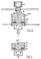
- Fig. 6
- eine Draufsicht auf das Gerät der Fig. 5 mit einem Doppelbehandlungszylinder für zwei Extremitäten,
- Fig. 7
- eine schematische Darstellung der Steuerelemente des Gerätes,
- Fig. 8
- eine Schnittansicht eines Regelventils zur Regulierung der Intensität des Über - und Unterdruckes, in geschlossenem Zustand,
- Fig. 9
- eine Schnittansicht des Regelventils der Fig. 8 in geöffnetem Zustand,
- Fig. 10
- eine Schnittansicht eines elektrischen Regelventils zur Regelung der Intensität des Über - und Unterdruckes.
- Fig. 1
- 2 shows a sectional view of a treatment cylinder with a closure device,
- Fig. 2
- 2 shows a front view of the treatment cylinder with the closure device according to FIG. 1,
- Fig. 3
- 2 shows a sectional view of the closure device with an extremity during an overpressure phase in the cylinder,
- Fig. 4
- 2 shows a sectional view of the closure device with an extremity during a negative pressure phase in the cylinder,
- Fig. 5
- a side view, partially in section, of a device with a treatment cylinder and locking device,
- Fig. 6
- 5 shows a plan view of the device of FIG. 5 with a double treatment cylinder for two extremities,
- Fig. 7
- a schematic representation of the control elements of the device,
- Fig. 8
- 1 shows a sectional view of a control valve for regulating the intensity of the overpressure and underpressure, in the closed state,
- Fig. 9
- 8 shows a sectional view of the control valve of FIG. 8 in the open state,
- Fig. 10
- a sectional view of an electrical control valve for controlling the intensity of the positive and negative pressure.
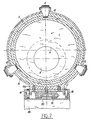
Die Fig. 1 zeigt einen Behandlungszylinder 1, vorzugsweise aus Plexiglas,
der an den Enden A und B mit einem Ring 2 aus demselben Material versehen ist,
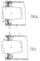
der eine Ringrippe 3 aufweist. Das Ende A trägt eine dickwandige Gummischeibe
4, die eine Öffnung 5 hat. Die Flachseiten der Gummischeibe 4 sind mit sehr
elastischen, dünnwandigen Gummimembranen 6 und 7 kaschiert, wobei die
Kaschierung nur auf einem äusseren Ring der Gummischeibe 4 erfolgt, wie es die
Fig. 3 und 4 zeigen. Die Durchmesser der Öffnungen 8 und 9 der
Gummimembranen 6 und 7 sind kleiner als der Durchmesser der Öffnung 5 der
Gummischeibe 4. Diese Anordnung dient als Verschlussmanschette C, die sich
um eine zu behandelnde Extremität E, wie in den Fig. 3 und 4 dargestellt, legt. Die
Fig. 3 zeigt, dass sich die Gummimembran 7 während einer Überdruckphase im
Zylinder 1 an die Extremität E anschmiegt und dass sich die Gummimembran 6,
dank eines gewollten Lecks zwischen der Extremität E und der Gummimembran
7, aufbläst, sodass zwischen beiden eine Luftkissen 6A entsteht, das als nicht
komprimierende Dichtung dient. Während einer Unterdruckphase erfolgt dieser
Vorgang umgekehrt, wie es die Fig. 4 illustriert.1 shows a treatment cylinder 1, preferably made of plexiglass,
which is provided at the ends A and B with a
Das Ende B des Behandlungszylinders 1 trägt ebenfalls eine dickwandige
Gummischeibe 10, die aber keine Öffnung 5 hat und daher den
Behandlungszylinder 1 am Ende B hermetisch verschliesst.The end B of the treatment cylinder 1 also has a thick
Die Manschette C wird mittels einem starren Ring 11 und Spannern 12
gegen die Ringrippe 3 gepresst, die in das Gummimaterial eindringt und somit
einen hermetischen Verschluss an dieser Stelle gewährleistet. The cuff C is by means of a rigid ring 11 and tensioners 12th
pressed against the
Die Gummischeibe 10 am Ende B des Zylinders 1 wird mittels einem
starren Ring 13 und Spannern 14 gegen eine Ringrippe 3 gepresst, sodass das
Ende B hermetisch verschlossen ist.The
Es ist von Vorteil, dass das Ende B geöffnet werden kann, speziell für den Fall gelähmter Patienten, die die zu behandelnde Extremität nicht bewegen und somit nicht richtig in den Behandlungszylinder 1 legen können.It is advantageous that the end B can be opened, especially for the Case of paralyzed patients who do not move the limb to be treated and can therefore not place correctly in the treatment cylinder 1.
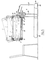
Der Umfang des Behandlungszylinders 1 ist am Ende A mit einem
Metallring 15 und am Ende B mit einem Metallring 16 versehen, an denen, an
Verdickungen 15a und 16a ein Flachteil 17 befestigt ist.The scope of the treatment cylinder 1 is at the end A with a
Das Flachteil 17 ist mit Rollen 18 versehen, die auf einem Trägerbalken 22
laufen und die gestatten, den Behandlungszylinder 1 axial zu bewegen, was das
Einlegen einer Extremität erleichtert.The
Das Flachteil 17 trägt am Ende A ein Gelenk 19, das gestattet, den
Behandlungszylinder 1, wie in Fig. 5 gestrichelt gezeigt, in Hochlage zu bringen,
wobei eine Strebe 20 in Nuten 21 des Trägerbalkens 22 einrastet und somit auch
eine axiale Bewegung des Behandlungszylinders verhindert.The
Die Verwendung von Rollen 18, um eine axiale Verschiebung des
Behandlungszylinders 1 zu schaffen, ist speziell für tragbare Behandlungszylinder
1 vorgesehen, wobei die Steuerorgane und die Vakuum - und Druckpumpe sich in
einem, ebenfalls tragbaren, aber nicht dargestellten Gehäuse befinden. Eine
solche Ausführung kann dienlich sein, wenn man einen gehunfähigen Patienten
zuhause behandeln muss, oder bei Sportveranstaltungen, wo die Über - und
Unterdruckbehandlung bei Verstauchungen, Krämpfen oder Prellungen mit
Hämatomen sehr wirksam ist.The use of
Wird hingegen der Behandlungszylinder, wie in der Fig. 5 gezeigt, von
einem Gerät G getragen, bei dem der Trägerbalken 22 mit dem Gerät G
beweglich verbunden ist, so kann man auf die Rollen 18 verzichten, weil das
gesamte Gerät G, mit Rollen 23 versehen, mobil ist, sodass man also zur
leichteren Einführung einer Extremität in den Behandlungszylinder 1, das gesamte
Gerät G verschieben kann. Eine nicht dargestellte Blockiervorrichtung verhindert
ein Bewegen des Gerätes G.If, on the other hand, the treatment cylinder, as shown in FIG
a device G worn, in which the
Die Ausführung gemäss der Fig. 5 ist vorteilhaft, weil man den Behandlungszylinder 1 in der Höhe verstellen kann, was gestattet wie gezeigt, einen Patienten, auf einem Stuhl sitzend, zu behandeln, oder den Behandlungszylinder 1 so hoch zu stellen, dass er auf einem Massagetisch oder Bett liegen kann, wie es die Höhe D illustriert. Letzendlich zeigt die Stellung F des Behandlungszylinders 1 die Hochlage, in welche er während der gesamten Behandlungssitzung gebracht werden kann.5 is advantageous because the Can adjust the height of the treatment cylinder 1, which allows, as shown, to treat a patient sitting in a chair, or the To set treatment cylinder 1 so high that it is on a massage table or Bed can lie, as illustrated by the height D. Ultimately, position F of the Treatment cylinder 1 the high position, in which he during the entire Treatment session can be brought.
Das Gerät G hat einen Sockel 24, der mit den Rollen 23 versehen ist und
einen Sitz 25 aufweist, in dem eine Stütze 26 beweglich gelagert ist. Auf dem
Sockel ist ein Gehäuse 27 befestigt, in dem sich, wie in Fig. 7 gezeigt, eine
Vakuum - und Druckpumpe 28, ein Magnetventil 29 für Unterdruck und ein
Magnetventil 30 für Überdruck befinden. Das Magnetventil 29 ist an ein Zeitrelais
31 und das Magnetventil 30 an ein Zeitrelais 32 angeschlossen. Die Zeitrelais 31,
32 gestatten, den Unter - und Überdruck während einer vorausbestimmten Zeit
konstant zu halten, z.B. hält man bei einer Arteriopathie obliterans, Stadium II,
Gehstrecke 200 m, die Unterdruckphase 45 Sekunden und die Überdruckphase
30 Sekunden konstant, wobei nach Ablauf der eingestelltenThe device G has a base 24 which is provided with the
Zeiten, das Zeitrelais 31 das Magnetventil 29 schliesst und das
Magnetventil 30 öffnet, oder das Zeitrelais 32 das Magnetventil 30 schliesst und
das Magnetventil 29 öffnet.Times, the
Die Intensitäten des Über - und Unterdruckes werden mittels Regelventilen
33 und 34, wie in den Fig. 8 und 9 illustriert, gesteuert. Die Ventile 33 und 34
bestehen aus einem Ventilkörper 35, einer Elastomerdichtung 36, die mit einem
Schraubteil 37 in ihren Sitz 38 gedrückt ist, einem Kolben 39 und einem Drehkopf
40.The intensities of the overpressure and underpressure are controlled by means of
Vor dem Einstellen der Druckwerte befinden sich die Regelventile 33 und
34 in geöffneter Stellung, wie in Fig. 9 dargestellt. Diese Stellung wird mittels dem
Kolben 39, der ein Gewinde 41 aufweist und vom Drehkopf 40 bewegt wird,
eingestellt. Dazu verformt der Kolben 39 die Elastomerdichtung 36 derart, dass
eine untere Querbohrung 42 des Kolbens 39, die in einen Axialkanal 43 und von
diesem in eine obere Querbohrung 44 mündet, geöffnet wird. Dreht man den
Drehkopf, z.B. im Uhrzeigersinn, so geht die Dichtung 36 nach und nach in ihre
Ausgangstellung zurück und verschliesst somit fortlaufend die untere
Querbohrung 42. Der Durchflussquerschnitt derselben wird so verändert, dass es
zu derjenigen Drosselung kommt, die demjenigen Über - oder Unterdruck
entspricht, den man erreichen will. Beim Regelventil 33 saugt die Pumpe 28 bei
geöffnetem Magnetventil 29 über die obere Querbohrung 44, den Axialkanal 43
und die untere Querbohrung 42 Aussenluft an und beim Regenventil 34 fördert die
Pumpe 28 Luft nach aussen über die untere Querbohrung 42, den Axialkanal 43
und die obere Querbohrung. Durch diese gewollten Lecks kann man die
gewünschten Druckwerte einstellen, wobei der Kompressor 28, trotz den Lecks
die eingestellten Druckwerte konstant hält.The
Es ist selbstverständlich, dass der Gang des Gewindes 41 so gewählt ist,
dass eine Drehung von 300° einen Überdruck von maximal 152 mmHg zulässt.
Grössere Druckwerte werden durch nichtdargestellte Sicherheitsventile
vermieden.It goes without saying that the
Die Fig. 10 zeigt ein ganz neuartiges Regelventil zum Einstellen der Über -
und Unterdruckwerte, das elektronisch gesteuert wird. Es besteht aus einem
Ventilkörper 49, in dem ein elektrischer Zugmagnet 50 gelagert ist, dessen
Ankerachse 51 einen Kolben 52 trägt, der mit einem O-Ring 53 versehen ist und
mit einer Feder 54 in seinen Sitz 55 gedrückt wird, wobei die Kraft der Feder so
gewählt ist, dass sie einerseits das Gewicht des Kolben 52 aufhebt und
andererseits den O-Ring 53 so an den Sitz 55 andrückt, dass in der Kammer 56
zuerst ein Überdruck und in der Kammer 57 ein Unterdruck herrschen muss, um
den O-Ring 53 aus seinem Sitz 55 wegzudrücken. Zu diesem Zweck hat die
Kammer 56 eine Gewindebohrung 58, über die ein aus dem Behandlungszylinder
kommender Überdruck gelangt, und die Kammer 57 hat eine Gewindebohrung 59;
über die der Behandlungszylinder 1 Luft ansaugt. Die Regulierung der Druckwerte
erfolgt durch eine veränderbare Spannungsspeisung des Zugmagneten 50, z.B.
24 Volt für einen Druck oder Sog von 152 mmHg und 9 Volt für einen Druck oder
Sog von 0.38 mmHg (0.05 atü). Sobald die eingestellten Druckwerte in den
Kammern 56 und 57 erreicht sind, drücken oder saugen sie den Kolben 52 und
somit den O-Ring 53 aus seinem Sitz 55, sodass überschüssiger Über - oder
Unterdruck über Magnetventile entweichen kann, wodurch die eingestellten
Druckwerte konstant gehalten werden können. Der Ventilkörper 49 ist auf der
Seite der Kammer 57 mit einem Schraubdeckel 68 und einem O-Ring 61 dichtend
verschlossen. Die gegenüberliegende Seite des Ventilkörpers 49 ist mit einem
Schraubdeckel 62 und einem O-Ring 63 dichtend verschlossen, wobei der
Schraubdeckel 62 eine Stopfbüchse 64 aufweist, die zum Abdichten des
Ventilkörpers entlang eines Leitungskabels 65 des Zugmagneten 50 dient.10 shows a completely new control valve for setting the overflow
and vacuum levels that are electronically controlled. It consists of one
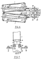
Die Fig. 6 zeigt das Gerät G mit zwei Behandlunszylindern 1 ausgestattet,
um gleichzeitig zwei Extremitäten zu behandeln, was ggf. über eine Reflexwirkung
der gesünderen Extremität die kränkere günstig beeinflussen kann. Eine
Schalttafel 46 zeigt eine Schaltuhr 47, mit der die Dauer einer Sitzung eingestellt
wird, einen Druckanzeiger 48, sowie die Skalen 33 und 34 der Regelventile und
deren Zeitrelais 31 und 32.6 shows the device G equipped with two treatment cylinders 1,
to treat two extremities at the same time, which may have a reflex effect
the healthier extremity can favorably affect the sicker. A
Control panel 46 shows a
Das Gerät G wird mit einer Behandlungstabelle geliefert, die gestattet das Gerät G sofort für die Behandlung von peripheren Kreislausfstörungen einzusetzen, wobei die Tabelle der Pathologie und deren Schweregrad Rechnung trägt. Es bleibt dem Arzt überlassen, die Über - und Unterdruckwerte und deren Konstanthaltezeiten jedem Fall individuell anzupassen.The device G is supplied with a treatment table that allows this Device G immediately for the treatment of peripheral aphid disorders insert, taking into account the table of pathology and its severity wearing. It is up to the doctor to determine the positive and negative pressure values and their Constant times can be individually adjusted in each case.
Um einerseits die Gummimembranen 6 und 7 bestens an die zu
behandelnde Extremität anzuschmiegen und andererseits die, durch eine
Kreislaufstörung übermässig entstehenden Metaboliten zu eliminieren, beginnt
eine Behandlungssitzung immer mit einer Überdruckphase, gefolgt von einer
Unterdruckphase, wobei die Dauer der Konstanthaltung des Über - und
Unterdruckes von der Pathologie und deren Schweregrad abhängt. On the one hand to the
Die oben beschriebene Ausführungsbeispiele sollten natürlich auf keinen
Fall einen begrenzenden Charakter besitzen, sondern können in dem im
unabhängigen Anspruch definierten Rahmen jedmögliche wünschenswerte
Abänderung erfahren. So können die Scheibe 4 und die Membranen 6, 7 aus
irgendeinem angemessenen Material bestehen, zum Beispiel aus einem
künstlichem oder natürlichem Elastomer. Es hat sich also vorteilhaft erwiesen, die
Scheibe 4 und die Membranen 6, 7 aus demselben Gummi herzustellen, dessen
Härte weniger als 50° shore beträgt. Der Durchmesser der Öffnung 5 der Scheibe
4 ist vorteilhafterweise mindestens 4 cm grösser als die Öffnungen 8,9 der
Membranen 6,7. Die Luftzu - und abführeinrichtung und die Steuer - und
Regelmittel könnten auch anders realisiert sein, so zum Beispiel mittels
Komputerkontrollierter pulsierender Elektroventile, deren Frequenz einstellbar ist.
Die Behandlungszylinder könnten auch einen nicht runden, zum Beispiel
polygonalen, rechteckigen Querschnitt aufweisen. Die Öffnungen der Scheibe und
der Membranen können zentral oder exzentrisch angeordnet sein, wobei eine
zentrale Anordnung den venösen Rückfluss je nach Ausstattung der
Behandlungszylinder verbessern kann, und wobei in den letzteren auch
gepolsterte Aufstützmittel für das zu behandelnde Körperglied vorgesehen sein
können.The exemplary embodiments described above should of course not apply to any
Case have a limiting character, but can in the
independent claim defined framework any desirable
Experience change. So the
Claims (11)
- Device for treating peripheral circulatory disorders, consisting of at least one treatment cylinder (1) into which a body limb (E) to be treated can be inserted at least in part via a closing device, and in which via air admission and relief devices controlled by control elements (28 - 34) a positive or/and negative pressure can be generated, with a closing device according to claim 9 being employed.
- Device according to claim 1, characterized in that the support element is formed by a rigid ring (2) having at least one annular rib (3) against which sleeve (C) is sealingly applied by means of clamping means.
- Device according to claim 1 or claim 2, characterized in that membranes (6, 7) are attached to disc (4), only over the width that is pressed against the rigid support element (2).
- Device according to one of claims 1 to 3, characterized in that disc (4) and membranes (6, 7) are made of an elastomer, and preferably of rubber.
- Device according to claim 1, characterized in that the treatment cylinder (1) is provided with a ring (2) at a first end (A) and at a second end (B), and that rings (2) have annular ribs (3) against which by means of rigid rings (11, 13) and tensioners (12, 14) that are used as clamping means, the sleeve (C) is applied at the first end (A) and a disc (10) without apertures is applied at the second end (B), in such a way that the annular ribs (3) penetrate into the sleeve (3) and disc (10).
- Device according to claim 1, characterized in that both ends (A, B) of the treatment cylinder (1) are provided with metal rings (15, 16) having bulges (15a, 16a), in that bulges (15a, 16a) are connected with a flat part (17), in that the flat part (17) is provided with rollers (18) rolling on a support beam (22), and in that the flat part (17) has an articulation (19) and a brace (20) engaging into the grooves (21) of the support beam (22).
- Device according to claim 1, characterized in that the treatment cylinder (1) is supported movably in a seat (25) of the device (G) by means of a support beam (22) and a bracket (26), in that the device (G) has rollers (23) that can be blocked, in that a housing (27) that is fastened to a base (24) of the device (G) contains control elements (28, 29, 30, 31, 32, 33, 34) that are linked to a control panel (46) and can be controlled by means of manipulating organs (40) while the control elements are arranged in such a way that a vacuum and pressure pump (28) is put in operation when a timer (47) is turned on, that depending on the settings of the manipulating organs (40) a phase of positive pressure and a phase of negative pressure having different intensities are produced in alternation in the treatment cylinder (1) while timing relays (31, 32) allow these phases to be kept constant for a predetermined length of time, a first timing relay (31) closing a first electromagnetic valve (29), opening a second electromagnetic valve (30), and turning on a second timing relay (32) which, after a predetermined length of time of constant pressure, closes the second electromagnetic valve (30), opens the first electromagnetic valve (29), and turns on the first timing relay (31), the alternating phases of positive and negative pressure being finally terminated after a length of time of the treatment that had been set on the timer (47).
- Device according to claim 1 or 7, characterized in that the air admission and relief device has valves (33, 34) with a valve body (35) in which a packing (36) is resting in a seat (38) while being pressed into place by a screw part (37), in that the packing (36) engages into a plunger (39), thus closing off a lower transverse bore (42) that is in communication with an axial channel (43) terminating in an upper transverse bore (44), in that plunger (39) has a thread (41) such that by turning a rotating knob (40) it can be screwed into the valve body (35) so that the plunger (39) will deform the packing (36) in such a way that at least part of the lower transverse bore (42) is opened, and when the plunger (39) is unscrewed from the valve body (35) the packing will once again close off the lower transverse bore (42).
- Closing device for a treatment cylinder (1) in a device for treating peripheral circulatory disorders according to claim 1 that has at least one treatment cylinder (1) into which a body limb (E) to be treated can be inserted at least in part via the closing device, and in which via air admission and relief devices controlled by control elements (28 - 34) a positive or/and negative pressure can be generated, where the closing device has a sleeve (C) with a thick-walled disc (4) covered on both of its flat sides by thin-walled, highly elastic membranes (6, 7), the disc (4) being provided with a first aperture (5) and the membranes (6, 7) being provided with second apertures (8, 9) situated so as to face the first aperture (5) and having a smaller diameter than the first aperture (5), the closing device having a rigid support element (2) fastened to the treatment cylinder (1) against which by means of clamping means (11, 12) the entire sleeve (C) is sealingly applied, the membranes (6, 7) being attached to disc (4) only along an outer annular part of this disc (4) while the remaining part of the membranes (6, 7) is floating freely relative to the disc (4) so that the second apertures (8, 9) of the membranes (6, 7) will cling to the body limb and an air cushion (6A) is formed between the membranes.
- Closing device according to claim 9, characterized in that the disc (4) and the membranes (6, 7) are made of rubber having a shore hardness of less than 50 degrees.
- Closing device according to claim 9, characterized in that the diameter of the first aperture (5) of disc (4) is at least 4 cm larger than that of the second apertures (8, 9) of membranes (6, 7).
Applications Claiming Priority (3)
| Application Number | Priority Date | Filing Date | Title |
|---|---|---|---|
| CH261897 | 1997-11-13 | ||
| CH261897 | 1997-11-13 | ||
| PCT/IB1998/001795 WO1999025305A1 (en) | 1997-11-13 | 1998-11-11 | Device for treating peripheral circulatory disorders and closing device for a treatment cylinder thereof |
Publications (2)
| Publication Number | Publication Date |
|---|---|
| EP1030640A1 EP1030640A1 (en) | 2000-08-30 |
| EP1030640B1 true EP1030640B1 (en) | 2003-07-23 |
Family
ID=4237813
Family Applications (1)
| Application Number | Title | Priority Date | Filing Date |
|---|---|---|---|
| EP98950266A Expired - Lifetime EP1030640B1 (en) | 1997-11-13 | 1998-11-11 | Device for treating peripheral circulatory disorders and closing device for a treatment cylinder thereof |
Country Status (8)
| Country | Link |
|---|---|
| US (1) | US6500192B1 (en) |
| EP (1) | EP1030640B1 (en) |
| JP (1) | JP2001522706A (en) |
| AT (1) | ATE245402T1 (en) |
| AU (1) | AU9641098A (en) |
| CA (1) | CA2310594A1 (en) |
| DE (1) | DE59809107D1 (en) |
| WO (1) | WO1999025305A1 (en) |
Cited By (1)
| Publication number | Priority date | Publication date | Assignee | Title |
|---|---|---|---|---|
| DE102004034625A1 (en) * | 2004-07-16 | 2006-02-09 | Rösch, Alfons | Procedure for the treatment of the lymph oedema and cramps enclosing the body part in sleeve connected to a vacuum source |
Families Citing this family (4)
| Publication number | Priority date | Publication date | Assignee | Title |
|---|---|---|---|---|
| US8535691B2 (en) * | 2006-02-16 | 2013-09-17 | Peach Technologies, LLC. | Perflurochemical treatment process and apparatus |
| US8529527B2 (en) * | 2007-05-31 | 2013-09-10 | Aoti, Inc. | Controller for an extremity hyperbaric device |
| WO2010011205A1 (en) * | 2008-07-25 | 2010-01-28 | Horvat Branimir L | Sequential distributor of gases and liquids |
| AU2015259316B2 (en) | 2014-05-14 | 2018-08-02 | Huntsman Advanced Materials Americas Llc | Multifunctional polyamides for protective coatings |
Family Cites Families (8)
| Publication number | Priority date | Publication date | Assignee | Title |
|---|---|---|---|---|
| US2113253A (en) | 1935-12-24 | 1938-04-05 | Western Electric Co | Therapeutic apparatus |
| US2082190A (en) | 1936-02-15 | 1937-06-01 | Taylor Instrument Co | Combined treatment chamber and cuff |
| US3329142A (en) | 1963-06-21 | 1967-07-04 | Welton Whann R | Means and method for exercising joints and improving blood and lymph circulation therein |
| AT301746B (en) | 1969-01-27 | 1972-09-11 | Contimed Sa | Medical treatment device |
| US4624248A (en) * | 1983-02-07 | 1986-11-25 | David Clark Company Incorporated | Transparent pressure garment |
| DE3710403A1 (en) | 1987-03-28 | 1988-10-06 | Lechler Elring Dichtungswerke | COMPLETE PISTON |
| DE8905848U1 (en) | 1989-05-10 | 1989-07-13 | Seiberth, Arno, 6720 Speyer, De | |
| US6007559A (en) * | 1998-06-12 | 1999-12-28 | Aci Medical | Vascular assist methods and apparatus |
-
1998
- 1998-11-11 AU AU96410/98A patent/AU9641098A/en not_active Abandoned
- 1998-11-11 DE DE59809107T patent/DE59809107D1/en not_active Expired - Fee Related
- 1998-11-11 AT AT98950266T patent/ATE245402T1/en not_active IP Right Cessation
- 1998-11-11 WO PCT/IB1998/001795 patent/WO1999025305A1/en active IP Right Grant
- 1998-11-11 JP JP2000520740A patent/JP2001522706A/en not_active Abandoned
- 1998-11-11 CA CA002310594A patent/CA2310594A1/en not_active Abandoned
- 1998-11-11 US US09/554,411 patent/US6500192B1/en not_active Expired - Fee Related
- 1998-11-11 EP EP98950266A patent/EP1030640B1/en not_active Expired - Lifetime
Cited By (2)
| Publication number | Priority date | Publication date | Assignee | Title |
|---|---|---|---|---|
| DE102004034625A1 (en) * | 2004-07-16 | 2006-02-09 | Rösch, Alfons | Procedure for the treatment of the lymph oedema and cramps enclosing the body part in sleeve connected to a vacuum source |
| DE102004034625B4 (en) * | 2004-07-16 | 2006-07-20 | Rösch, Alfons | Procedure for the treatment of the lymph oedema and cramps enclosing the body part in sleeve connected to a vacuum source |
Also Published As
| Publication number | Publication date |
|---|---|
| EP1030640A1 (en) | 2000-08-30 |
| ATE245402T1 (en) | 2003-08-15 |
| CA2310594A1 (en) | 1999-05-27 |
| WO1999025305A1 (en) | 1999-05-27 |
| AU9641098A (en) | 1999-06-07 |
| JP2001522706A (en) | 2001-11-20 |
| DE59809107D1 (en) | 2003-08-28 |
| US6500192B1 (en) | 2002-12-31 |
Similar Documents
| Publication | Publication Date | Title |
|---|---|---|
| DE69819910T2 (en) | DEVICE FOR COMPRESSION TREATMENT OF LIMBS | |
| DE69916569T2 (en) | Air massager | |
| DE2417624C2 (en) | Device for mechanical heart stimulation | |
| DE1903217A1 (en) | Device for stimulating the flow of fluids inside the limbs of the body of living beings | |
| DE19828588C2 (en) | Transportable device for intermittent compression to support the return transport of body fluid towards the heart, and use of this device | |
| EP1030640B1 (en) | Device for treating peripheral circulatory disorders and closing device for a treatment cylinder thereof | |
| EP1307168B1 (en) | Slimming device | |
| DE102006059786A1 (en) | Low pressure cuff for treating parts of body with reduced pressure, has chambers or hoses for generating a suction or pressurizing effect | |
| DE1906509C3 (en) | Device for the treatment of circulatory disorders | |
| DE3836787C2 (en) | ||
| DE2432126C3 (en) | Automatic therapy device for treatment with liquid jets | |
| DE19524380C2 (en) | Massage device, in particular for use in decongestive therapy | |
| EP3213734B1 (en) | Device for cleaning, massaging and/or caring the lower extremities | |
| DE3440638A1 (en) | DEVICE FOR MASSING THE EXTREMITIES OF THE BODY, e.g. THE LEGS | |
| DE2340617C2 (en) | Device for draining cerebrospinal fluid from the cerebral cavity and valve therefor | |
| DE2613529A1 (en) | Hydrotherapeutic underwater massager for domestic bath tub - has distribauator hose under pressure with nozzled discharging through bath inlets | |
| DE4435308A1 (en) | Massage device with driven massage head | |
| DE102006033033B4 (en) | compression bandage | |
| EP3810220A1 (en) | Implant for providing a shunt having an adjustable flow rate | |
| DE202004004852U1 (en) | Medical stocking for e.g. supporting joints, contains chamber for filling with pressurised medium | |
| DE3037435A1 (en) | Body organ reflex therapy appts. - massages specific foot sole areas by corresponding pressure jet nozzles in foot support plates | |
| DE102008050587B4 (en) | Bath for use for medical, therapeutic and body hygiene purposes | |
| DE102020127568A1 (en) | Device for massage, blood and lymph drainage and rhythm transmission | |
| DE3833050A1 (en) | Haemorrhoid treatment device | |
| CH650667A5 (en) | Foot reflex zone water-massaging apparatus |
Legal Events
| Date | Code | Title | Description |
|---|---|---|---|
| PUAI | Public reference made under article 153(3) epc to a published international application that has entered the european phase |
Free format text: ORIGINAL CODE: 0009012 |
|
| 17P | Request for examination filed |
Effective date: 20000509 |
|
| AK | Designated contracting states |
Kind code of ref document: A1 Designated state(s): AT BE DE DK ES FI FR GB GR IE IT LU NL PT SE |
|
| GRAH | Despatch of communication of intention to grant a patent |
Free format text: ORIGINAL CODE: EPIDOS IGRA |
|
| GRAH | Despatch of communication of intention to grant a patent |
Free format text: ORIGINAL CODE: EPIDOS IGRA |
|
| GRAA | (expected) grant |
Free format text: ORIGINAL CODE: 0009210 |
|
| AK | Designated contracting states |
Designated state(s): AT BE DE DK ES FI FR GB GR IE IT LU NL PT SE |
|
| PG25 | Lapsed in a contracting state [announced via postgrant information from national office to epo] |
Ref country code: NL Free format text: LAPSE BECAUSE OF FAILURE TO SUBMIT A TRANSLATION OF THE DESCRIPTION OR TO PAY THE FEE WITHIN THE PRESCRIBED TIME-LIMIT Effective date: 20030723 Ref country code: IT Free format text: LAPSE BECAUSE OF FAILURE TO SUBMIT A TRANSLATION OF THE DESCRIPTION OR TO PAY THE FEE WITHIN THE PRESCRIBED TIME-LIMIT;WARNING: LAPSES OF ITALIAN PATENTS WITH EFFECTIVE DATE BEFORE 2007 MAY HAVE OCCURRED AT ANY TIME BEFORE 2007. THE CORRECT EFFECTIVE DATE MAY BE DIFFERENT FROM THE ONE RECORDED. Effective date: 20030723 Ref country code: IE Free format text: LAPSE BECAUSE OF FAILURE TO SUBMIT A TRANSLATION OF THE DESCRIPTION OR TO PAY THE FEE WITHIN THE PRESCRIBED TIME-LIMIT Effective date: 20030723 Ref country code: GB Free format text: LAPSE BECAUSE OF FAILURE TO SUBMIT A TRANSLATION OF THE DESCRIPTION OR TO PAY THE FEE WITHIN THE PRESCRIBED TIME-LIMIT Effective date: 20030723 Ref country code: FR Free format text: LAPSE BECAUSE OF FAILURE TO SUBMIT A TRANSLATION OF THE DESCRIPTION OR TO PAY THE FEE WITHIN THE PRESCRIBED TIME-LIMIT Effective date: 20030723 Ref country code: FI Free format text: LAPSE BECAUSE OF FAILURE TO SUBMIT A TRANSLATION OF THE DESCRIPTION OR TO PAY THE FEE WITHIN THE PRESCRIBED TIME-LIMIT Effective date: 20030723 |
|
| REG | Reference to a national code |
Ref country code: GB Ref legal event code: FG4D Free format text: NOT ENGLISH |
|
| REG | Reference to a national code |
Ref country code: IE Ref legal event code: FG4D Free format text: GERMAN |
|
| REF | Corresponds to: |
Ref document number: 59809107 Country of ref document: DE Date of ref document: 20030828 Kind code of ref document: P |
|
| PG25 | Lapsed in a contracting state [announced via postgrant information from national office to epo] |
Ref country code: SE Free format text: LAPSE BECAUSE OF FAILURE TO SUBMIT A TRANSLATION OF THE DESCRIPTION OR TO PAY THE FEE WITHIN THE PRESCRIBED TIME-LIMIT Effective date: 20031023 Ref country code: GR Free format text: LAPSE BECAUSE OF FAILURE TO SUBMIT A TRANSLATION OF THE DESCRIPTION OR TO PAY THE FEE WITHIN THE PRESCRIBED TIME-LIMIT Effective date: 20031023 Ref country code: DK Free format text: LAPSE BECAUSE OF FAILURE TO SUBMIT A TRANSLATION OF THE DESCRIPTION OR TO PAY THE FEE WITHIN THE PRESCRIBED TIME-LIMIT Effective date: 20031023 |
|
| PG25 | Lapsed in a contracting state [announced via postgrant information from national office to epo] |
Ref country code: ES Free format text: LAPSE BECAUSE OF FAILURE TO SUBMIT A TRANSLATION OF THE DESCRIPTION OR TO PAY THE FEE WITHIN THE PRESCRIBED TIME-LIMIT Effective date: 20031103 |
|
| PG25 | Lapsed in a contracting state [announced via postgrant information from national office to epo] |
Ref country code: LU Free format text: LAPSE BECAUSE OF NON-PAYMENT OF DUE FEES Effective date: 20031111 Ref country code: AT Free format text: LAPSE BECAUSE OF NON-PAYMENT OF DUE FEES Effective date: 20031111 |
|
| PG25 | Lapsed in a contracting state [announced via postgrant information from national office to epo] |
Ref country code: BE Free format text: LAPSE BECAUSE OF NON-PAYMENT OF DUE FEES Effective date: 20031130 |
|
| NLV1 | Nl: lapsed or annulled due to failure to fulfill the requirements of art. 29p and 29m of the patents act | ||
| PG25 | Lapsed in a contracting state [announced via postgrant information from national office to epo] |
Ref country code: PT Free format text: LAPSE BECAUSE OF FAILURE TO SUBMIT A TRANSLATION OF THE DESCRIPTION OR TO PAY THE FEE WITHIN THE PRESCRIBED TIME-LIMIT Effective date: 20031223 |
|
| GBV | Gb: ep patent (uk) treated as always having been void in accordance with gb section 77(7)/1977 [no translation filed] |
Effective date: 20030723 |
|
| REG | Reference to a national code |
Ref country code: IE Ref legal event code: FD4D |
|
| PLBE | No opposition filed within time limit |
Free format text: ORIGINAL CODE: 0009261 |
|
| STAA | Information on the status of an ep patent application or granted ep patent |
Free format text: STATUS: NO OPPOSITION FILED WITHIN TIME LIMIT |
|
| BERE | Be: lapsed |
Owner name: *WERDING WINFRIED Effective date: 20031130 |
|
| PG25 | Lapsed in a contracting state [announced via postgrant information from national office to epo] |
Ref country code: DE Free format text: LAPSE BECAUSE OF NON-PAYMENT OF DUE FEES Effective date: 20040602 |
|
| 26N | No opposition filed |
Effective date: 20040426 |
|
| EN | Fr: translation not filed |