EP1030459A2 - CDMA multipath receiver - Google Patents
CDMA multipath receiver Download PDFInfo
- Publication number
- EP1030459A2 EP1030459A2 EP20000103314 EP00103314A EP1030459A2 EP 1030459 A2 EP1030459 A2 EP 1030459A2 EP 20000103314 EP20000103314 EP 20000103314 EP 00103314 A EP00103314 A EP 00103314A EP 1030459 A2 EP1030459 A2 EP 1030459A2
- Authority
- EP
- European Patent Office
- Prior art keywords
- despreading
- reception signal
- code
- transmission paths
- multiplying
- Prior art date
- Legal status (The legal status is an assumption and is not a legal conclusion. Google has not performed a legal analysis and makes no representation as to the accuracy of the status listed.)
- Granted
Links
Images


Classifications
-
- H—ELECTRICITY
- H04—ELECTRIC COMMUNICATION TECHNIQUE
- H04B—TRANSMISSION
- H04B1/00—Details of transmission systems, not covered by a single one of groups H04B3/00 - H04B13/00; Details of transmission systems not characterised by the medium used for transmission
- H04B1/69—Spread spectrum techniques
- H04B1/707—Spread spectrum techniques using direct sequence modulation
- H04B1/7097—Interference-related aspects
- H04B1/711—Interference-related aspects the interference being multi-path interference
- H04B1/7115—Constructive combining of multi-path signals, i.e. RAKE receivers
Definitions
- the present invention relates to a receiver, and more particularly to a receiver for use in a CDMA (Code Division Multiplex Access) communication system.
- CDMA Code Division Multiplex Access
- Receivers for use in broadband CDMA communication systems which are expected to be next-generation portable telephone system standards should comprise RAKE receivers for removing multipath fading interference.
- multiplier 102 in transmitter 101 spreads transmission data x(t) by multiplying it by spreading code c(t), and the transmitter 101 transmits the spread data as transmission signal s(t).
- the transmission signal s(t) transmitted from the transmitter 101 is subjected to multipath fading over a plurality of transmission paths 103-1 through 103-N with respective delays ⁇ 1 - ⁇ N . Thereafter, the signal is received as a reception signal r(t) by a RAKE receiver 104.
- the transmission signal s(t) is given the respective delays ⁇ 1 - ⁇ N , and the results are multiplied by respective coefficients a 1 - a N representing respective phase/amplitude ratios of the transmission paths.
- the signals from the transmission paths 103-1 through 103-N are then added together, producing the reception signal r(t).
- the RAKE receiver 104 has a plurality of fingers comprising a plurality of delay units 110-1 - 110-N for giving delays ⁇ 1 - ⁇ N depending on the respective transmission paths to the reception signal r(t), a plurality of multipliers 120-1 - 120-N for multiplying signals which are produced by delaying the reception signal r(t) for the delays ⁇ 1 - ⁇ N with the delay units 110-1 - 110-N, by a complex conjugate value c(t)* of c(t), and outputting product signals, a plurality of integrators 130-1 - 130-N for integrating the product signals from the multipliers 120-1 - 120-N for the period of one symbol, and outputting integrals f 1,n - f N,n , respectively, a plurality of multipliers 140-1 - 140-N for multiplying the integrals f 1,n - f N,n outputted from the integrators 130-1 - 130-N by complex conjug
- Multiplying the integrals f 1,n - f N,n outputted from the integrators 130-1 - 130-N by the complex conjugate values a 1 * - a N * with the multipliers 140-1 - 140-N is equivalent to correcting carrier phase differences caused between the transmission paths over the transmission paths and weighting the signals depending on amplitude differences between the transmission paths. Therefore, when the signals outputted from the multipliers 140-1 - 140-N are added by the adder 150, their vectors can be combined for a maximum S/N ratio.
- the delay units 110-1 - 110-N give the reception signal r(t) the delay times ⁇ i of the transmission paths, as shown by the equation (4) below. Then, the multipliers 120-1 - 120-N multiplies the signals from the delay units 110-1 - 110-N by the complex conjugate value c(t)* of the spreading code. Thereafter, the integrators 130-1 - 130-N integrate the product signals from the multipliers 120-1 - 120-N for the period of one symbol, producing integrals f j,n .
- the integrals f j,n outputted from the integrators 130-1 - 130-N are represented by the sum of the products of the transmission data series x n and the phase/amplitude ratios of the transmission paths, and interferences I j,n composed of signal components from other transmission paths having different delay times.
- the multipliers 140-1 - 140-N multiply the integrals f j,n outputted from the integrators 130-1 - 130-N by the complex conjugate values a j * of the phase/amplitude ratios of the transmission paths. Thereafter, the adder 150 adds the outputs from the fingers together, and outputs the sum as the output signal series Rn, as shown by the equations (6), (7) below.
- the multipliers 140-1 - 140-N multiply the integrals f j,n by the complex conjugate values a j * of the phase/amplitude ratios, the phase errors of the respective paths are corrected, and the signals are weighted for a maximum S/N ratio.
- the RAKE receiver tends to have a large circuit scale because it needs to have a plurality of despreaders parallel to each other for despreading the reception signal.
- terminals which have the RAKE receiver are required to have a small circuit scale in view of demands for a low price and power requirements.
- terminals have a large circuit scale due to the incorporation of the RAKE receiver, then the price and power requirements of the terminals cannot be reduced.
- a plurality of delay means add delays over transmission paths to a complex conjugate value of a spreading code used when a reception signal is transmitted, and output delayed signals.
- a plurality of multiplying means multiply the delayed signals outputted from the delay means by complex conjugate values of coefficients representing respective phase/amplitude ratios of the transmission paths, and output product signals.
- An adding means adds the product signals outputted from the multiplying means, and outputs the sum as a code for despreading the reception signal.
- a despreading means despreads the reception signal using the code outputted from the adding means.
- the receiver according to the present invention is reduced in circuit scale.
- a receiver comprises a despreading code calculator 1 for calculating a despreading code c x (t) for despreading a reception signal r(t) based on delays given to the reception signal r(t) over a plurality of transmission paths through which the reception signal r(t) is transmitted and coefficients representing respective phase/amplitude ratios of the transmission paths, a despreader 20 for despreading the reception signal r(t) using the despreading code c x (t) calculated by the despreading code calculator 1, and an integrator 30 for integrating the reception signal despread by the despreader 20 and outputting the integrated signal as a reception signal series Rn.
- a despreading code calculator 1 for calculating a despreading code c x (t) for despreading a reception signal r(t) based on delays given to the reception signal r(t) over a plurality of transmission paths through which the reception signal r(t) is transmitted and coefficients representing respective phase
- the despreading code calculator 1 comprises a plurality of delay units 10-1 - 10-N for adding delays ⁇ 1 - ⁇ N over the transmission paths through which the reception signal r(t) is transmitted, to complex conjugate value c(t)* of the spreading code, and outputting delayed signals, a plurality of multipliers 40-1 - 40-N for multiplying the delayed signals outputted from the delay units 10-1 - 10-N by complex conjugate values a 1 * - a N * of coefficients a 1 - a N by which the transmission signal has been multiplied, and outputting product signals, and an adder 50 for adding the product signals outputted from the multipliers 40-1 - 40-N, and outputting the sum as the despreading code c x (t).
- the reception signal r(t) is not branched into as many as signals as the number of transmission paths for being delayed and corrected in phase. Instead, the delays ⁇ 1 - ⁇ N over the transmission paths through which the reception signal r(t) is transmitted are added to the code c(t)* used to despread the reception signal r(t) for delaying and correcting the reception signal r(t) in phase and adding amplitude weights to the reception signal r(t).
- the delayed signals are multiplied by the complex conjugate values a 1 * - a N * of the coefficients a 1 - a N by which the transmission signal has been multiplied over the respective transmission paths, thereby producing the code c x (t) for despreading the reception signal r(t).
- the reception signal r(t) is despread into the reception signal series Rn.
- the code c(t)* used to despread the reception signal r(t) is given the delays over the respective transmission paths, the delayed codes are multiplied by the complex conjugate values representing the phase/amplitude ratios of the transmission paths, and the product signals are added into the code c x (t) for despreading the reception signal.
- the reception signal r(t) is thereafter despread by the code c x (t).
- the receiver according to the embodiment of the present invention can thus comprise a single finger.
- the receiver can be constructed of a single despreader only, and hence can be of a highly simplified circuit arrangement.
- the despreading code may be calculated and stored as a table if fading parameters (delay times and phase/amplitude ratios) suffer no time-dependent variations or slow time-dependent variations.
Abstract
Description
- The present invention relates to a receiver, and more particularly to a receiver for use in a CDMA (Code Division Multiplex Access) communication system.
- Receivers for use in broadband CDMA communication systems which are expected to be next-generation portable telephone system standards should comprise RAKE receivers for removing multipath fading interference.
- In a CDMA communication system, as shown in Fig. 1 of the accompanying drawings, multiplier 102 in
transmitter 101 spreads transmission data x(t) by multiplying it by spreading code c(t), and thetransmitter 101 transmits the spread data as transmission signal s(t). - The transmission signal s(t) transmitted from the
transmitter 101 is subjected to multipath fading over a plurality of transmission paths 103-1 through 103-N with respective delays τ1 - τN. Thereafter, the signal is received as a reception signal r(t) by aRAKE receiver 104. - Specifically, over the respective transmission paths 103-1 - 103-N, the transmission signal s(t) is given the respective delays τ1 - τN, and the results are multiplied by respective coefficients a1 - aN representing respective phase/amplitude ratios of the transmission paths. The signals from the transmission paths 103-1 through 103-N are then added together, producing the reception signal r(t).
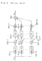
- As shown in Fig. 2 of the accompanying drawings, the
RAKE receiver 104 has a plurality of fingers comprising a plurality of delay units 110-1 - 110-N for giving delays τ1 - τN depending on the respective transmission paths to the reception signal r(t), a plurality of multipliers 120-1 - 120-N for multiplying signals which are produced by delaying the reception signal r(t) for the delays τ1 - τN with the delay units 110-1 - 110-N, by a complex conjugate value c(t)* of c(t), and outputting product signals, a plurality of integrators 130-1 - 130-N for integrating the product signals from the multipliers 120-1 - 120-N for the period of one symbol, and outputting integrals f1,n - fN,n, respectively, a plurality of multipliers 140-1 - 140-N for multiplying the integrals f1,n - fN,n outputted from the integrators 130-1 - 130-N by complex conjugate values a1* - aN* of the respective coefficients a1 - aN, and outputting product signals, and anadder 150 for adding the product signals from the multipliers 140-1 - 140-N and outputting the sum as an output signal series Rn. The reception signal r(t) should ideally be branched into as many as signals as the number of transmission paths, but may not be so branched because of limitations on the circuit scale. - Multiplying the integrals f1,n - fN,n outputted from the integrators 130-1 - 130-N by the complex conjugate values a1* - aN* with the multipliers 140-1 - 140-N is equivalent to correcting carrier phase differences caused between the transmission paths over the transmission paths and weighting the signals depending on amplitude differences between the transmission paths. Therefore, when the signals outputted from the multipliers 140-1 - 140-N are added by the
adder 150, their vectors can be combined for a maximum S/N ratio. - A process of transmitting and receiving data in the above CDMA communication system will be described below in specific detail with reference to Figs. 1 and 2.
- The transmission signal s(t) transmitted from the transmitter is produced by multiplying the transmission data x(t) by the spreading code c(t), as shown by the following equation (1):
- The transmission data x(t) is represented by a signal where the value of a transmission data series xn continues for a symbol interval T, as shown by the following equation (2):
- The reception signal r(t) which has been subjected to multipath fading is produced by giving the respective delays τi of the transmission paths to the transmission signal s(t), multiplying the results by the respective coefficients ai representing phase/amplitude ratios of the respective transmission paths, and adding the signals from all the transmission paths, producing the reception signal r(t), as shown by the following equation (3):
- In the fingers of the receiver, the delay units 110-1 - 110-N give the reception signal r(t) the delay times τi of the transmission paths, as shown by the equation (4) below. Then, the multipliers 120-1 - 120-N multiplies the signals from the delay units 110-1 - 110-N by the complex conjugate value c(t)* of the spreading code. Thereafter, the integrators 130-1 - 130-N integrate the product signals from the multipliers 120-1 - 120-N for the period of one symbol, producing integrals fj,n. As shown by the equation (5) below, the integrals fj,n outputted from the integrators 130-1 - 130-N are represented by the sum of the products of the transmission data series xn and the phase/amplitude ratios of the transmission paths, and interferences Ij,n composed of signal components from other transmission paths having different delay times.
- Then, the multipliers 140-1 - 140-N multiply the integrals fj,n outputted from the integrators 130-1 - 130-N by the complex conjugate values aj* of the phase/amplitude ratios of the transmission paths. Thereafter, the
adder 150 adds the outputs from the fingers together, and outputs the sum as the output signal series Rn, as shown by the equations (6), (7) below. When the multipliers 140-1 - 140-N multiply the integrals fj,n by the complex conjugate values aj* of the phase/amplitude ratios, the phase errors of the respective paths are corrected, and the signals are weighted for a maximum S/N ratio. - The RAKE receiver tends to have a large circuit scale because it needs to have a plurality of despreaders parallel to each other for despreading the reception signal.
- However, terminals which have the RAKE receiver are required to have a small circuit scale in view of demands for a low price and power requirements.
- If terminals have a large circuit scale due to the incorporation of the RAKE receiver, then the price and power requirements of the terminals cannot be reduced.
- It is therefore an object of the present invention to provide a CDMA receiver which has a relatively small circuit scale, and yet is capable of performing functions equivalent to those of the conventional CDMA receivers.
- In a receiver according to the present invention, a plurality of delay means add delays over transmission paths to a complex conjugate value of a spreading code used when a reception signal is transmitted, and output delayed signals. A plurality of multiplying means multiply the delayed signals outputted from the delay means by complex conjugate values of coefficients representing respective phase/amplitude ratios of the transmission paths, and output product signals. An adding means adds the product signals outputted from the multiplying means, and outputs the sum as a code for despreading the reception signal. A despreading means despreads the reception signal using the code outputted from the adding means.
- Since the code for despreading the reception signal is calculated on the basis of the delays given to the reception signal over transmission paths and the coefficients representing the respective phase/amplitude ratios of the transmission paths, and the reception signal is despread using the calculated code, it is not necessary to provide as many despreading circuits as the number of the transmission paths. Therefore, the receiver according to the present invention is reduced in circuit scale.
- The above and other objects, features, and advantages of the present invention will become apparent from the following descriptions with reference to the accompanying drawings which illustrate examples of the present invention.
- Fig. 1 is a block diagram illustrative of a process of transmitting data in a CDMA communication system;
- Fig. 2 is a block diagram of a RAKE receiver;
- Fig. 3 is a block diagram of a receiver according to an embodiment of the present invention; and
- Fig. 4 is a block diagram of a simplified representation of the receiver shown in Fig. 3.
-
- As shown in Fig. 3, a receiver according to an embodiment of the present invention comprises a
despreading code calculator 1 for calculating a despreading code cx(t) for despreading a reception signal r(t) based on delays given to the reception signal r(t) over a plurality of transmission paths through which the reception signal r(t) is transmitted and coefficients representing respective phase/amplitude ratios of the transmission paths, adespreader 20 for despreading the reception signal r(t) using the despreading code cx(t) calculated by the despreadingcode calculator 1, and anintegrator 30 for integrating the reception signal despread by thedespreader 20 and outputting the integrated signal as a reception signal series Rn. - The despreading
code calculator 1 comprises a plurality of delay units 10-1 - 10-N for adding delays τ1 - τN over the transmission paths through which the reception signal r(t) is transmitted, to complex conjugate value c(t)* of the spreading code, and outputting delayed signals, a plurality of multipliers 40-1 - 40-N for multiplying the delayed signals outputted from the delay units 10-1 - 10-N by complex conjugate values a1* - aN* of coefficients a1 - aN by which the transmission signal has been multiplied, and outputting product signals, and anadder 50 for adding the product signals outputted from the multipliers 40-1 - 40-N, and outputting the sum as the despreading code cx(t). - In the receiver shown in Fig. 3, the reception signal r(t) is not branched into as many as signals as the number of transmission paths for being delayed and corrected in phase. Instead, the delays τ1 - τN over the transmission paths through which the reception signal r(t) is transmitted are added to the code c(t)* used to despread the reception signal r(t) for delaying and correcting the reception signal r(t) in phase and adding amplitude weights to the reception signal r(t). Thereafter, the delayed signals are multiplied by the complex conjugate values a1* - aN* of the coefficients a1 - aN by which the transmission signal has been multiplied over the respective transmission paths, thereby producing the code cx(t) for despreading the reception signal r(t).
- Using the despreading code cx(t), the reception signal r(t) is despread into the reception signal series Rn.
- The equation (7) referred to above can be modified into the following equations (8) - (11):
- When the equation (9) is expressed by a block form, the circuit shown in Fig. 3 is achieved.
- As described above, rather than despreading the reception signal r(t) into as many signals as the transmission paths and adding the despread signals into the reception signal series Rn, the code c(t)* used to despread the reception signal r(t) is given the delays over the respective transmission paths, the delayed codes are multiplied by the complex conjugate values representing the phase/amplitude ratios of the transmission paths, and the product signals are added into the code cx(t) for despreading the reception signal. The reception signal r(t) is thereafter despread by the code cx(t). The receiver according to the embodiment of the present invention can thus comprise a single finger.
- If the despreading code cx(t) is calculated in advance and stored in a
memory 60, as shown in Fig. 4, then the receiver can be constructed of a single despreader only, and hence can be of a highly simplified circuit arrangement. - In the circuit shown in Fig. 4, the despreading code may be calculated and stored as a table if fading parameters (delay times and phase/amplitude ratios) suffer no time-dependent variations or slow time-dependent variations.
- While a preferred embodiment of the present invention has been described using specific terms, such description is for illustrative purposes only, and it is to be understood that changes and variations may be made without departing from the spirit or scope of the following claims.
Claims (8)
- A receiver comprising:despreading code calculating means for calculating a code for despreading a reception signal based on delays given to the reception signal over a plurality of transmission paths through which the reception signal is transmitted and coefficients representing respective phase/amplitude ratios of the transmission paths;despreading means for despreading the reception signal using the code calculated by said despreading code calculating means; andintegrating means for integrating the reception signal despread by said despreading means.
- A receiver comprising:memory means for storing a code for despreading a reception signal, calculated in advance based on delays given to the reception signal over a plurality of transmission paths through which the reception signal is transmitted and coefficients representing respective phase/amplitude ratios of the transmission paths;despreading means for despreading the reception signal using the code stored by said memory means; andintegrating means for integrating the reception signal despread by said despreading means.
- A receiver according to claim 1, wherein said despreading code calculating means comprises:a plurality of delay means for adding the delays over the transmission paths to a complex conjugate value of a spreading code used when the reception signal is transmitted, and outputting delayed signals;a plurality of multiplying means for multiplying the delayed signals outputted from said delay means by complex conjugate values of the coefficients representing the respective phase/amplitude ratios of the transmission paths, and outputting product signals; andadding means for adding the product signals outputted from said multiplying means, and outputting the sum as the code for despreading the reception signal.
- A receiver according to claim 1, further comprising memory means for storing the code outputted from said despreading code calculating means, said despreading means comprising means for despreading said reception signal using the code stored by said memory means.
- A receiver according to claim 3, further comprising memory means for storing the code outputted from said adding means, said despreading means comprising means for despreading said reception signal using the code stored by said memory means.
- A receiver according to claim 3, wherein there are as many said delay means and said multiplying means as the number of the transmission paths.
- A receiver according to claim 5, wherein there are as many said delay means and said multiplying means as the number of the transmission paths.
- A method for despreading a reception signal comprising method steps corresponding to the features of any of claims 1 to 7.
Applications Claiming Priority (2)
| Application Number | Priority Date | Filing Date | Title |
|---|---|---|---|
| JP4142799 | 1999-02-19 | ||
| JP4142799A JP3173600B2 (en) | 1999-02-19 | 1999-02-19 | Receiving machine |
Publications (3)
| Publication Number | Publication Date |
|---|---|
| EP1030459A2 true EP1030459A2 (en) | 2000-08-23 |
| EP1030459A3 EP1030459A3 (en) | 2002-10-30 |
| EP1030459B1 EP1030459B1 (en) | 2007-11-21 |
Family
ID=12608077
Family Applications (1)
| Application Number | Title | Priority Date | Filing Date |
|---|---|---|---|
| EP20000103314 Expired - Lifetime EP1030459B1 (en) | 1999-02-19 | 2000-02-18 | CDMA multipath receiver |
Country Status (5)
| Country | Link |
|---|---|
| US (1) | US6888812B1 (en) |
| EP (1) | EP1030459B1 (en) |
| JP (1) | JP3173600B2 (en) |
| AU (1) | AU733612B2 (en) |
| DE (1) | DE60037153T2 (en) |
Families Citing this family (5)
| Publication number | Priority date | Publication date | Assignee | Title |
|---|---|---|---|---|
| US7301993B2 (en) * | 2002-09-13 | 2007-11-27 | Broadcom Corporation | Channel estimation in a spread spectrum receiver |
| JP2005354255A (en) * | 2004-06-09 | 2005-12-22 | Fujitsu Ltd | Device and method for eliminating interference |
| US20060164145A1 (en) * | 2005-01-21 | 2006-07-27 | Andrei Poskatcheev | Method and apparatus for creating variable delay |
| US8743848B2 (en) * | 2009-05-26 | 2014-06-03 | Broadcom Corporation | Hybrid location determination for wireless communication device |
| US8229041B2 (en) * | 2009-05-26 | 2012-07-24 | Broadcom Corporation | Direct detection of wireless interferers in a communication device for multiple modulation types |
Citations (1)
| Publication number | Priority date | Publication date | Assignee | Title |
|---|---|---|---|---|
| US5835527A (en) * | 1995-01-04 | 1998-11-10 | Interdigital Technology Corporation | Spread spectrum adaptive power control system and method |
Family Cites Families (9)
| Publication number | Priority date | Publication date | Assignee | Title |
|---|---|---|---|---|
| JPH05292063A (en) | 1992-04-06 | 1993-11-05 | Nippon Telegr & Teleph Corp <Ntt> | Spread spectrum receiver |
| JPH05292059A (en) | 1992-04-10 | 1993-11-05 | Toshiba Corp | Spread spectrum receiver |
| US5305349A (en) * | 1993-04-29 | 1994-04-19 | Ericsson Ge Mobile Communications Inc. | Quantized coherent rake receiver |
| US5644592A (en) * | 1995-04-24 | 1997-07-01 | California Institute Of Technology | Parallel interference cancellation for CDMA applications |
| JPH0974372A (en) | 1995-09-04 | 1997-03-18 | Matsushita Electric Ind Co Ltd | Spread spectrum radio transmitter-receiver |
| JP3745430B2 (en) | 1995-12-22 | 2006-02-15 | 株式会社エヌ・ティ・ティ・ドコモ | CDMA multipath search method and CDMA signal receiver |
| JPH10200503A (en) | 1997-01-09 | 1998-07-31 | Matsushita Electric Ind Co Ltd | Adaptive equalizing circuit for spread spectrum communication |
| JP3406831B2 (en) * | 1998-03-19 | 2003-05-19 | 富士通株式会社 | Array antenna system for wireless base station |
| US6507604B1 (en) * | 2000-08-31 | 2003-01-14 | Wen-Yi Kuo | Rake receiver for CDMA wireless communications |
-
1999
- 1999-02-19 JP JP4142799A patent/JP3173600B2/en not_active Expired - Fee Related
-
2000
- 2000-02-15 AU AU16426/00A patent/AU733612B2/en not_active Ceased
- 2000-02-17 US US09/505,662 patent/US6888812B1/en not_active Expired - Fee Related
- 2000-02-18 DE DE2000637153 patent/DE60037153T2/en not_active Expired - Fee Related
- 2000-02-18 EP EP20000103314 patent/EP1030459B1/en not_active Expired - Lifetime
Patent Citations (1)
| Publication number | Priority date | Publication date | Assignee | Title |
|---|---|---|---|---|
| US5835527A (en) * | 1995-01-04 | 1998-11-10 | Interdigital Technology Corporation | Spread spectrum adaptive power control system and method |
Non-Patent Citations (1)
| Title |
|---|
| PATENT ABSTRACTS OF JAPAN vol. 1997, no. 11, 28 November 1997 (1997-11-28) & JP 09 181704 A (N T T IDO TSUSHINMO KK), 11 July 1997 (1997-07-11) * |
Also Published As
| Publication number | Publication date |
|---|---|
| US6888812B1 (en) | 2005-05-03 |
| JP3173600B2 (en) | 2001-06-04 |
| EP1030459B1 (en) | 2007-11-21 |
| DE60037153T2 (en) | 2008-03-20 |
| DE60037153D1 (en) | 2008-01-03 |
| JP2000244453A (en) | 2000-09-08 |
| AU1642600A (en) | 2000-08-24 |
| EP1030459A3 (en) | 2002-10-30 |
| AU733612B2 (en) | 2001-05-17 |
Similar Documents
| Publication | Publication Date | Title |
|---|---|---|
| US6404759B1 (en) | CDMA multi-user receiving apparatus including interference canceller with optimal receiving state | |
| US6600729B1 (en) | DS-CDMA multi-user interference canceller and DS-CDMA Communication system | |
| US6882682B1 (en) | Fixed pattern detection apparatus | |
| EP1279239B1 (en) | Matched filter and receiver for mobile radio communication system | |
| US8295417B2 (en) | Method and apparatus for efficient estimation of interference in a wireless receiver | |
| WO2005034404A2 (en) | Rake-based cdma receivers for multiple receiver antennas | |
| US6888877B2 (en) | CDMA receiver | |
| US6888812B1 (en) | CDMA receiver | |
| EP1229667A2 (en) | Selection of multiple propagation paths by successive removal and detection of high autocorrelations | |
| JP3886709B2 (en) | Spread spectrum receiver | |
| EP0911990A2 (en) | Receiver apparatus for CDMA communication system | |
| EP2485417A1 (en) | Method and device for selecting noise path | |
| JPH0832548A (en) | Synchronization tracking method | |
| US7573934B2 (en) | Spread spectrum rake receiver | |
| JP4298655B2 (en) | UMTS signal detection method and detection apparatus | |
| JPH0832547A (en) | Synchronization acquisition method | |
| JPH07264112A (en) | Method for eliminating interference of code division multiple address communication | |
| US6801568B2 (en) | Despreading apparatus and method for CDMA signal | |
| EP1548953B1 (en) | Spread spectrum rake receiver | |
| EP1039653A2 (en) | Apparatus and method for receiving and despreading DS-CDMA signals | |
| JP2001136105A (en) | Matched filter and receiver | |
| CN102299726A (en) | Spread spectrum communication system, idle channel estimating device and relevant method | |
| JPS6336698B2 (en) | ||
| JPH09162779A (en) | Receiving device for code division multiple connecting communication | |
| JP2001036501A (en) | Interference canceller device and method for detecting path timing |
Legal Events
| Date | Code | Title | Description |
|---|---|---|---|
| PUAI | Public reference made under article 153(3) epc to a published international application that has entered the european phase |
Free format text: ORIGINAL CODE: 0009012 |
|
| AK | Designated contracting states |
Kind code of ref document: A2 Designated state(s): AT BE CH CY DE DK ES FI FR GB GR IE IT LI LU MC NL PT SE |
|
| AX | Request for extension of the european patent |
Free format text: AL;LT;LV;MK;RO;SI |
|
| PUAL | Search report despatched |
Free format text: ORIGINAL CODE: 0009013 |
|
| AK | Designated contracting states |
Kind code of ref document: A3 Designated state(s): AT BE CH CY DE DK ES FI FR GB GR IE IT LI LU MC NL PT SE |
|
| AX | Request for extension of the european patent |
Free format text: AL;LT;LV;MK;RO;SI |
|
| 17P | Request for examination filed |
Effective date: 20021004 |
|
| AKX | Designation fees paid |
Designated state(s): DE FR GB |
|
| 17Q | First examination report despatched |
Effective date: 20060516 |
|
| GRAP | Despatch of communication of intention to grant a patent |
Free format text: ORIGINAL CODE: EPIDOSNIGR1 |
|
| GRAS | Grant fee paid |
Free format text: ORIGINAL CODE: EPIDOSNIGR3 |
|
| GRAA | (expected) grant |
Free format text: ORIGINAL CODE: 0009210 |
|
| AK | Designated contracting states |
Kind code of ref document: B1 Designated state(s): DE FR GB |
|
| REG | Reference to a national code |
Ref country code: GB Ref legal event code: FG4D |
|
| REF | Corresponds to: |
Ref document number: 60037153 Country of ref document: DE Date of ref document: 20080103 Kind code of ref document: P |
|
| ET | Fr: translation filed | ||
| PLBE | No opposition filed within time limit |
Free format text: ORIGINAL CODE: 0009261 |
|
| STAA | Information on the status of an ep patent application or granted ep patent |
Free format text: STATUS: NO OPPOSITION FILED WITHIN TIME LIMIT |
|
| 26N | No opposition filed |
Effective date: 20080822 |
|
| PGFP | Annual fee paid to national office [announced via postgrant information from national office to epo] |
Ref country code: DE Payment date: 20090213 Year of fee payment: 10 |
|
| PGFP | Annual fee paid to national office [announced via postgrant information from national office to epo] |
Ref country code: GB Payment date: 20090217 Year of fee payment: 10 |
|
| PGFP | Annual fee paid to national office [announced via postgrant information from national office to epo] |
Ref country code: FR Payment date: 20090213 Year of fee payment: 10 |
|
| GBPC | Gb: european patent ceased through non-payment of renewal fee |
Effective date: 20100218 |
|
| REG | Reference to a national code |
Ref country code: FR Ref legal event code: ST Effective date: 20101029 |
|
| PG25 | Lapsed in a contracting state [announced via postgrant information from national office to epo] |
Ref country code: FR Free format text: LAPSE BECAUSE OF NON-PAYMENT OF DUE FEES Effective date: 20100301 |
|
| PG25 | Lapsed in a contracting state [announced via postgrant information from national office to epo] |
Ref country code: DE Free format text: LAPSE BECAUSE OF NON-PAYMENT OF DUE FEES Effective date: 20100901 |
|
| PG25 | Lapsed in a contracting state [announced via postgrant information from national office to epo] |
Ref country code: GB Free format text: LAPSE BECAUSE OF NON-PAYMENT OF DUE FEES Effective date: 20100218 |