EP1029387B1 - Crimping tool - Google Patents
Crimping tool Download PDFInfo
- Publication number
- EP1029387B1 EP1029387B1 EP98965073A EP98965073A EP1029387B1 EP 1029387 B1 EP1029387 B1 EP 1029387B1 EP 98965073 A EP98965073 A EP 98965073A EP 98965073 A EP98965073 A EP 98965073A EP 1029387 B1 EP1029387 B1 EP 1029387B1
- Authority
- EP
- European Patent Office
- Prior art keywords
- crimping tool
- screw
- tool according
- basic body
- crimp contacts
- Prior art date
- Legal status (The legal status is an assumption and is not a legal conclusion. Google has not performed a legal analysis and makes no representation as to the accuracy of the status listed.)
- Expired - Lifetime
Links
Images


Classifications
-
- H—ELECTRICITY
- H01—ELECTRIC ELEMENTS
- H01R—ELECTRICALLY-CONDUCTIVE CONNECTIONS; STRUCTURAL ASSOCIATIONS OF A PLURALITY OF MUTUALLY-INSULATED ELECTRICAL CONNECTING ELEMENTS; COUPLING DEVICES; CURRENT COLLECTORS
- H01R43/00—Apparatus or processes specially adapted for manufacturing, assembling, maintaining, or repairing of line connectors or current collectors or for joining electric conductors
- H01R43/04—Apparatus or processes specially adapted for manufacturing, assembling, maintaining, or repairing of line connectors or current collectors or for joining electric conductors for forming connections by deformation, e.g. crimping tool
- H01R43/048—Crimping apparatus or processes
- H01R43/055—Crimping apparatus or processes with contact member feeding mechanism
-
- Y—GENERAL TAGGING OF NEW TECHNOLOGICAL DEVELOPMENTS; GENERAL TAGGING OF CROSS-SECTIONAL TECHNOLOGIES SPANNING OVER SEVERAL SECTIONS OF THE IPC; TECHNICAL SUBJECTS COVERED BY FORMER USPC CROSS-REFERENCE ART COLLECTIONS [XRACs] AND DIGESTS
- Y10—TECHNICAL SUBJECTS COVERED BY FORMER USPC
- Y10S—TECHNICAL SUBJECTS COVERED BY FORMER USPC CROSS-REFERENCE ART COLLECTIONS [XRACs] AND DIGESTS
- Y10S72/00—Metal deforming
- Y10S72/712—Electrical terminal crimper
-
- Y—GENERAL TAGGING OF NEW TECHNOLOGICAL DEVELOPMENTS; GENERAL TAGGING OF CROSS-SECTIONAL TECHNOLOGIES SPANNING OVER SEVERAL SECTIONS OF THE IPC; TECHNICAL SUBJECTS COVERED BY FORMER USPC CROSS-REFERENCE ART COLLECTIONS [XRACs] AND DIGESTS
- Y10—TECHNICAL SUBJECTS COVERED BY FORMER USPC
- Y10T—TECHNICAL SUBJECTS COVERED BY FORMER US CLASSIFICATION
- Y10T29/00—Metal working
- Y10T29/49—Method of mechanical manufacture
- Y10T29/49002—Electrical device making
- Y10T29/49117—Conductor or circuit manufacturing
- Y10T29/49174—Assembling terminal to elongated conductor
- Y10T29/49181—Assembling terminal to elongated conductor by deforming
- Y10T29/49185—Assembling terminal to elongated conductor by deforming of terminal
-
- Y—GENERAL TAGGING OF NEW TECHNOLOGICAL DEVELOPMENTS; GENERAL TAGGING OF CROSS-SECTIONAL TECHNOLOGIES SPANNING OVER SEVERAL SECTIONS OF THE IPC; TECHNICAL SUBJECTS COVERED BY FORMER USPC CROSS-REFERENCE ART COLLECTIONS [XRACs] AND DIGESTS
- Y10—TECHNICAL SUBJECTS COVERED BY FORMER USPC
- Y10T—TECHNICAL SUBJECTS COVERED BY FORMER US CLASSIFICATION
- Y10T29/00—Metal working
- Y10T29/53—Means to assemble or disassemble
- Y10T29/5313—Means to assemble electrical device
- Y10T29/532—Conductor
- Y10T29/53209—Terminal or connector
- Y10T29/53213—Assembled to wire-type conductor
- Y10T29/53235—Means to fasten by deformation
Definitions
- the invention relates to a crimping tool for crimping crimp contacts, in particular of crimp contacts in tape form, with a pressing device comprising Base body and a table assigned to the base body for guidance of the crimp contacts, the crimp contacts being fed to the pressing device via the table and the position of the table relative to the base body along a tour is changeable.
- the invention relates to a crimping tool for crimping crimp contacts, especially of crimp contacts in tape form, with a pressing device comprehensive base body and a table assigned to the base body to guide the crimp contacts, the crimp contacts of the pressing device be fed to the table.
- Crimping tools of the type in question have long been known in practice and exist in a wide variety of embodiments.
- the known crimping tools are designed for the efficient processing of crimp contacts in tape form, in longitudinal or transverse transport or for sortable individual contacts.
- the known crimping tools are often designed as quick-change tools and can be used on individual workstations or fully automatic machines and transfer lines.
- the processing of electrical conductors with a cross-sectional area of approximately 0.08 mm 2 to 50 mm 2 is possible.
- the table is formed in two in the base body Grooves.
- the table is fixed relative to the base body using clamping screws.
- the Clamping screws are loosened first, then the position of the table adjusted and finally the clamping screws are tightened again.
- the adjusting mechanism of the known crimping tool comprises a mounting block 78, which is fastened to the base body 12 of the crimping tool.
- the assembly block 78 has a passage 86 through which an adjusting screw 92 passes is.
- the adjusting screw 92 is in a in the table 70 of the known crimping tool trained thread 90 screwed. By turning the screw 92 is the table 70 is displaceable perpendicular to the feed direction of the crimp contacts, wherein an elastic means 81 is arranged between the mounting block 78 and the table 70 is that the screw 92 by means of the table 70 against one on the mounting block 78 trained stop 88 presses.
- the screw 92 To adjust the screw 92, it is necessary that the screw 92 on her the screw head 95 facing away from a projection 96 with reduced Has diameter.
- the protrusion has a slot 98 for engagement with, for example a screwdriver. The movement of the screw 92 takes place exclusively via the projection 96, since the screw head 95 of the screw 92 is not accessible when the crimping tool is assembled.
- the adjusting mechanism known from the D1 is complex because it is a specially designed one Mounting block 78 and a specially designed screw 92 with a Projection 96 with a reduced diameter are to be used. Furthermore is the Actuating mechanism unsafe because of the formation of a screw 92 with a Projection 96 with a reduced diameter is virtually a "predetermined breaking point" in the area of the projection 96 is accepted. Especially with long operating times of the crimping tool and the associated increased stiffness of turning the screw due to possible contamination of the In extreme cases, the thread can break off the projection during a Adjustment process occur due to its reduced diameter. In one Fall must complete the Stellmechansimus including the mounting block 78 be dismantled to install a new screw 92.
- the claimed, described by claim 1 The crimping tool that solves the task outlined above is characterized by the features of the identifying parts characterized.
- the base body now has a thread, one of which acts as a stop acting screw is screwed, which is only passed through the table is.
- the elastic means presses the table against one assigned to the base body Stop, namely the screw or the head of the screw.
- the adjustment the position of the table relative to the base body is done in a simple manner by simply screwing the screw in or out. When screwing the entire diameter of the screw can act.
- the formation of a head start with a reduced diameter on the screw is not necessary. at For example, the use of a commercially available Allen screw Screw turned on her head, which also forms a stop for the table.
- the adjusting mechanism could be in between the table and the base body Include elastic means acting in the direction of the guide.
- the elastic means the table could still be against you press the stop assigned to the body. The position of the stop could then in turn be changed relative to the base body in the guide direction be, so that a positioning of the table only by changing the Position of the stop is realizable. This would have a particularly simple positioning result.
- the elastic means could be a coil spring in a structurally simple manner his. However, leaf springs or the like could also be used here.
- Another particularly simple embodiment could be realized in that the stop one led through the table and into a thread in the base body screwed screw, preferably an Allen screw.
- the adjustment could the position of the table relative to the base body by just one in or Unscrew the screw.
- the position of the table relative to the The base body would then be pressurized by the elastic means secured.
- the elastic means could continue in a recess in the Be arranged table. This would be a particularly safe and precise pressurization possible.
- the screw must be self-locking. This would involve the introduction of a plastic material conceivable in the thread in the base body. Alternatively or additionally the screw could be pressurized to prevent it from being unscrewed be secured. This pressurization could be caused by the elastic Successful means.
- Another way to secure the position of the screw in the thread could by means of a bolt screwed through the base body towards the screw respectively.
- the thread for the bolt would practically be in the thread reach into the screw.
- the bolt could be a Be grub screw.
- the stop could also be assigned to the table be, the screw then being screwed through the base body into the table would. Securing the screw against unintentional loosening could then be done analogously to the above.
- the Guide at least one and preferably two of the base body and / or the Include table associated pin or pins.
- the pens could then run in receptacles formed in the table or in the base body. Such Recordings could easily be made through drilling.
- pins with one could Dovetail profile or a square profile can be provided. In particular in the latter profile shapes, the formation of a pin would be safe Stop is enough.
- the table could also be guided in a conventional manner the main body formed groove. In this case, a safeguard against would be necessary provide for lifting the table out of the groove.
- the feed unit could be a thrust element and one that can be moved back and forth in the feed direction of the crimp contacts Include feed fingers, the feed finger with the thrust element over one Coupling element could be operatively connected.
- the feed finger could be guided along one side of the table, preferably by means of the table.
- the feed finger could quasi move within a groove, possibly by a Table side and a cover element arranged on the table side can be formed could.
- the cover element could be designed as a plate and screwed to the table side his.
- Crimping tool can be designed in a favorable manner such that the distance of the Advance finger to the table during and after actuation of the adjusting mechanism remains constant.
- the coupling element could be guided in the feed finger in this way be that the distance between the coupling element and feed finger during the Actuation of the adjusting mechanism changes to the same extent as the distance from Table and body. It would be a guide of the feed finger below the Tables in a groove made of two guide strips extending in the feed direction Cheap.
- the guide rails could either be integrally integrated into the table or screwed to the table from below.
- the coupling element could be perpendicular to the feed direction inside guided by two guide strips of the feed finger arranged in the form of a groove his. This would damage or impair the function of the Avoided crimping tool.
- the above object is accomplished in the manner according to the invention solved the features of claim 18.
- a crimping tool Crimping crimp contacts in particular crimp contacts in tape form
- a pressing device comprising a base body and a base body assigned table for guiding the crimp contacts
- the crimp contacts of the Pressing device can be fed over the table, designed such that the table a positioning device for the functional positioning of the crimp contacts covered relative to the table.
- the table is a positioning device assigned.
- the need to position the table relatively to the main body while accepting the known disadvantages is elegant Avoided way.
- the problem of a jamming feed finger, which is not adapted to an adjustment of the table no longer occur.
- the positioning device could one for positioning the crimp contacts perpendicular to the feed direction trained guide element include. That would be a simple requirement the feed direction for the crimp contacts conceivable.
- the guide element could be moved perpendicular to the feed direction his.
- the guide element could continue to be strip-shaped and vertical be arranged to the table surface.
- the guide element could be bent particularly securely between at least two Engage the contact elements of the crimp contacts when operating the crimping tool. In other words, it is perpendicular to the table surface strip-shaped guide element between contact elements projecting perpendicularly from the table of the crimp contacts on the table. It could the guide element can be aligned along a crimp contact strip.
- the distance could be used to adapt to differently dimensioned crimp contacts of the guide element can be changed relative to the table. It must be ensured that the crimp contacts or the crimp contact tape securely between the guide element and can slide through the table without any significant Movement of the crimp contacts perpendicular to the feed direction is possible.
- the guide element can be attached to the table by means of a holding device.
- the Holding device could comprise at least one rod, on one of which End of the guide element is fixed.
- the guide element could be fixed by clamping the guide element by means of a guided through the guide element and in the direction of the rod axis screw screwed into the rod on the rod. When assembled the rod could then be perpendicular to the feed direction and parallel to the Table level can be arranged level.
- the guide element on the table could have an elongated hole for the screw.
- a Distance or height adjustment of the guide element could then be easier Way by unscrewing the screw, moving the guide element and Tighten the screw.
- the holding device could comprise at least one receiving element for the rod or the rods.
- the receiving element could have at least one passage for the one or more Embrace bars.
- the receiving element could be in one piece with several Passages for holding several rods or as a single element for holding be formed only one rod.
- the Rod or rods in the passage can be clamped in different positions his. This would be a simple positioning of the guide element in one direction realized perpendicular to the feed direction. To ensure a safe Clamping the rod in the passageway could result in clamping through one Receiving element screwed clamping screw. That for the clamping screw the thread provided would then run virtually up to the passage.
- the receiving element could or the receiving elements could be arranged on the table surface and preferably screwed to it. Alternatively, the receiving elements could can also be arranged on any other side of the table.
- a crimping tool would also be conceivable, in which on the one hand an adjusting mechanism is provided for stepless positioning of the table along a guide and on the other hand a table with a positioning device for the functional Positioning the crimp contacts relative to the table includes.
- a Crimping tool could preferably have the features according to the subclaims partially or wholly realized.
- FIG. 1 shows an embodiment in a total of six front, top and side views a table 4 of a crimping tool according to the invention.
- the table 4 has a steep mechanism 6 for stepless Position the table 4 along a guide 5.
- the stele mechanism 6 comprises an elastic means 7 and a screw 10.
- the guide 5 is constructed in the form of two pins 12.
- the table 4 also has a positioning device 20 for functionally appropriate Position the crimp contacts 1 relative to the table 4.
- the positioning device 20 comprises a guide element 21 which is strip-shaped and vertical is arranged to the table surface in the feed direction 16.
- the guide element 21 engages between at least two bends during operation of the crimping tool Contact elements 22 of the crimp contacts 1.
- the guide element 21 is fastened to the table 4 by means of a holding device 23.
- the holding device 23 comprises two rods 24, at one end the guide element 21 is screwed tight with a screw 25.
- the guide element 21 has elongated holes 26. So that is the guide element can be changed in its position relative to the rods 24.
- the Bars 24 extend through passages 28 in a receiving element 27 of the Holding device 23.
- the receiving element 27 is arranged on the table surface and screwed to it.
- a feed finger 17, not shown here, is guided along the table side 19, wherein the guidance is optimized by means of a plate 29 screwed to the table side 19 is.
- FIG. 1 The second illustration from below in FIG. 1 also shows the table 4 in a top view, where a sectional view is chosen below the table surface level is. It can be seen that the screw 10 has a stop 8 for the table 4th forms. A recess is formed in the table below the table surface, which forms a guide area 33 for the feed finger 17.
- the three upper representations in the left half of FIG. 1 show a front view of the table 4 or the guide element 21.
- the passages 28 particularly well recognizable for receiving the rods 24.
- guide element 21 has two slots 26 for height adjustment of the guide element 21 relative to the table 4.
- the table 4 is shown in a side view. in this connection the guide area 33 is particularly well recognizable for the feed finger 17.
- the Table 4 also has a clamping device 30 for the crimp contacts 1. With the clamping device 30 is a lifting of the crimp contacts 1 or a tape avoided from crimp contacts 1 during operation of the crimping tool.
- FIG. 2 shows a schematic front view of the thrust element 15 of the feed unit 14.
- the thrust element 15 is the feed finger 17 via a coupling element 18 connected. So that the feed finger 17 during the change the table position relative to the base body 3 by means of the adjusting mechanism 6 not tilted in its guidance, there is a groove 31 in the feed finger 17 for guidance of the coupling element 18 is formed.
- the coupling element 18 is such in the feed finger 17 out that the distance from the coupling element 18 and Feed fingers 17 during the actuation of the actuating mechanism 6 to the same extent changed how the distance from table 4 and base body 3.
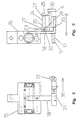
- Fig. 3 shows a schematic side view of the thrust element 15 with the Coupling element 18 and the table 4 of the embodiment.
- the clarity half of the feed finger 17 is not shown here.
- the table 4 has a guide 5 trained pins 12 for engagement with the base body 3.
- a positioning device 20 for crimp contacts 1 is assigned to the table.
- the positioning device 20 has a receiving element 27 for rods 24, on which a Guide element 21 is fastened with a screw 25.
- the bars 24 run in the receiving element 27 formed passages 28.
- a clamping screw 32 is provided for clamping the Bars 24 in the passage 28, a clamping screw 32 is provided.
- the bars 24 and the receiving element 27 together form a holding device 23.
- the table 4 has a guide area 33 for the here Feed finger 17, not shown.
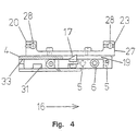
- FIG. 4 is a table 4 in a partially sectioned and schematic front view shown.
- a partially cut table 4 is the range of motion of the feed finger 17 along the table side 19 and in the guide area 33 can be seen particularly well.
- the groove 31 is for the coupling element 18 shown.
- the positioning device 20 with the holding device 23 and the Receiving element 27 shown. Passages 28 are provided for receiving rods 24 intended.
- the crimp contacts 1 are guided on a table 4 and have contact elements 22.
- the table 4 is relative movable to the base body 3, which has a pressing device 2.
- the leadership 5 for the table 4 relative to the base body 3 has an adjusting mechanism 6, with which the position of the table 4 is infinitely adjustable relative to the base body 3.
- the Guide 5 has pins 12 which are guided in receptacles 13 of the base body 3 are.
- the base body 3 is the feed unit 14 for the crimp contacts with the push element 15 assigned.
- the thrust element 15 is between two stops 35 forth. With each to and fro movement of the thrust element 15, the Band of crimp contacts 1 in the feed direction 16 to the pressing device 2 further conveyed.
- On the table 4 is a positioning device 20 with a guide element 21 arranged.
- the guide element 21 engages in the contact elements 22 of the Crimp contacts 1 on.
- the guide element 21 is via rods 24 and a receiving element 27 set on table 4.
- the feed finger 17 has a groove 31 for Engagement with the coupling element 18.
- a thread 34 for a bolt is formed in the base body 3.
- the bolt can be designed as a grub screw and is used for locking against the Screw 10 screwed.
Description
Die Erfindung betrifft ein Crimpwerkzeug zum Crimpen von Crimpkontakten, insbesondere von Crimpkontakten in Bandform, mit einem eine Preßeinrichtung umfassenden Grundkörper und einem dem Grundkörper zugeordneten Tisch zur Führung der Crimpkontakte, wobei die Crimpkontakte der Preßeinrichtung über den Tisch zugeführt werden und wobei die Position des Tischs relativ zum Grundkörper entlang einer Führung veränderbar ist.The invention relates to a crimping tool for crimping crimp contacts, in particular of crimp contacts in tape form, with a pressing device comprising Base body and a table assigned to the base body for guidance of the crimp contacts, the crimp contacts being fed to the pressing device via the table and the position of the table relative to the base body along a tour is changeable.
Des weiteren betrifft die Erfindung ein Crimpwerkzeug zum Crimpen von Crimpkontakten, insbesondere von Crimpkontakten in Bandform, mit einem eine Preßeinrichtung umfassenden Grundkörper und einem dem Grundkörper zugeordneten Tisch zur Führung der Crimpkontakte, wobei die Crimpkontakte der Preßeinrichtung über den Tisch zugeführt werden.Furthermore, the invention relates to a crimping tool for crimping crimp contacts, especially of crimp contacts in tape form, with a pressing device comprehensive base body and a table assigned to the base body to guide the crimp contacts, the crimp contacts of the pressing device be fed to the table.
Crimpwerkzeuge der in Rede stehenden Art sind seit langem aus der Praxis bekannt und existieren in unterschiedlichsten Ausführungsformen. Die bekannten Crimpwerkzeuge sind für eine rationelle Verarbeitung von Crimpkontakten in Bandform, in Längs- oder Quertransport oder für sortierfähige Einzelkontakte ausgelegt. Dabei sind die bekannten Crimpwerkzeuge häufig als Schnellwechselwerkzeuge ausgebildet und können auf Einzelarbeitsplätzen oder Vollautomaten und Transferstraßen eingesetzt werden. Dabei ist die Bearbeitung von elektrischen Leitern mit einer Querschnittsfläche von etwa 0,08 mm2 bis 50 mm2 möglich.Crimping tools of the type in question have long been known in practice and exist in a wide variety of embodiments. The known crimping tools are designed for the efficient processing of crimp contacts in tape form, in longitudinal or transverse transport or for sortable individual contacts. The known crimping tools are often designed as quick-change tools and can be used on individual workstations or fully automatic machines and transfer lines. The processing of electrical conductors with a cross-sectional area of approximately 0.08 mm 2 to 50 mm 2 is possible.
Im Hinblick auf eine stabile und präzise Crimpung ist erforderlich, daß die Crimpkontakte der Preßeinrichtung auf die Position des Crimpstempels abgestellt exakt zugeführt werden. Hierzu ist es bekannt, eine Positionierung des Tischs relativ zum Grundkörper entlang einer Führung vorzusehen. Hierdurch kann die Zuführrichtung der Crimpkontakte beeinflußt werden.With a view to stable and precise crimping it is necessary that the crimp contacts the pressing device exactly placed on the position of the crimping die become. For this purpose, it is known to position the table relative to the To provide basic body along a guide. This allows the feed direction of the crimp contacts are affected.
Bei einem bekannten Crimpwerkzeug ist der Tisch in zwei in dem Grundkörper ausgebildeten Nuten geführt. Die Festlegung des Tischs relativ zum Grundkörper erfolgt mittels Klemmschrauben. Zur Veränderung der Position des Tischs müssen die Klemmschrauben zunächst gelöst werden, anschließend wird die Position des Tischs eingestellt und abschließend werden die Klemmschrauben wieder angezogen.In a known crimping tool, the table is formed in two in the base body Grooves. The table is fixed relative to the base body using clamping screws. To change the position of the table, the Clamping screws are loosened first, then the position of the table adjusted and finally the clamping screws are tightened again.
Ein derartiges Positionieren des Tischs ist einerseits aufgrund der drei zuletzt genannten Arbeitsschritte aufwendig und andererseits ist ein Verkanten des Tischs in den nutartigen Führungen häufig nicht zu vermeiden. Dies erhöht den Verschleiß des Crimpwerkzeugs erheblich.Such positioning of the table is due to the last three on the one hand Steps are complex and on the other hand tilting the table in the groove-like guides are often unavoidable. This increases the wear of the Crimping tool considerably.
Des weiteren ist mit dem bekannten Positioniervorgang häufig keine ausreichend präzise Justierung des Tischs relativ zum Grundkörper möglich. Eine präzise Justierung ist jedoch deshalb wünschenswert, da selbst geringe Justierfehler bereits zur Ausbildung von häufig ungewünschten Aufbördelungen - sog. Crimp-Trompetchen - im Bereich der gepreßten Crimpkontakte führen. Furthermore, the known positioning process often does not suffice precise adjustment of the table relative to the base body possible. A precise adjustment However, it is desirable because even minor adjustment errors are already available Formation of frequently unwanted flares - so-called crimp trumpets - lead in the area of the pressed crimp contacts.
Die Lehre der vorliegenden Patentanmeldung gemäß dem Patentanspruch 1 geht vom Stand der Technik aus, der aus sich der US-A-5 577 318 (D1) ergibt. Aus der in Rede stehenden Entgegenhaltung ist ein Crimpwerkzeug mit allen Merkmalen des Oberbegriffs des Patentanspruchs 1 bekannt.The teaching of the present patent application according to claim 1 is based on the prior art, which results from US-A-5 577 318 (D1). From the document in question, a crimping tool with all the features of the preamble of claim 1 is known.
Der Stellmechanismus des bekannten Crimpwerkzeugs umfaßt einen Montageblock
78, der an dem Grundkörper 12 des Crimpwerkzeugs befestigt ist. Der Montageblock
78 weist einen Durchgang 86 auf, durch den eine Einstellschraube 92 geführt
ist. Die Einstellschraube 92 ist in ein in dem Tisch 70 des bekannten Crimpwerkzeugs
ausgebildetes Gewinde 90 geschraubt. Durch Drehen der Schraube 92 ist
der Tisch 70 senkrecht zur Zuführrichtung der Crimpkontakte verschiebbar, wobei
zwischen dem Montageblock 78 und dem Tisch 70 ein elastisches Mittel 81 angeordnet
ist, das die Schraube 92 mittels des Tischs 70 gegen einen an dem Montageblock
78 ausgebildeten Anschlag 88 drückt. The adjusting mechanism of the known crimping tool comprises a mounting block
78, which is fastened to the
Zur Verstellung der Schraube 92 ist es erforderlich, daß die Schraube 92 an ihrem dem Schraubenkopf 95 abgewandten Ende einen Vorsprung 96 mit reduziertem Durchmesser aufweist. Der Vorsprung weist einen Schlitz 98 zum Eingriff mit beispielsweise einem Schraubendreher auf. Die Bewegung der Schraube 92 erfolgt ausschließlich über den Vorsprung 96, da der Schraubenkopf 95 der Schraube 92 im montierten Zustand des Crimpwerkzeugs nicht zugänglich ist.To adjust the screw 92, it is necessary that the screw 92 on her the screw head 95 facing away from a projection 96 with reduced Has diameter. The protrusion has a slot 98 for engagement with, for example a screwdriver. The movement of the screw 92 takes place exclusively via the projection 96, since the screw head 95 of the screw 92 is not accessible when the crimping tool is assembled.
Der aus der D1 bekannte Stellmechanismus ist aufwendig, da ein speziell ausgestalteter Montageblock 78 sowie eine speziell ausgestaltete Schraube 92 mit einem Vorsprung 96 mit reduziertem Durchmesser einzusetzen sind. Des weiteren ist der Stellmechanismus unsicher, da durch die Ausbildung einer Schraube 92 mit einem Vorsprung 96 mit reduziertem Durchmesser quasi eine "Sollbruchstelle" im Bereich des Vorsprungs 96 in Kauf genommen wird. Insbesondere bei langen Betriebszeiten des Crimpwerkzeugs und einer damit verbundenen zunehmenden Schwergängigkeit des Drehens der Schraube aufgrund einer möglichen Verschmutzung des Gewindes kann hier im Extremfall ein Abbrechen des Vorsprungs während eines Justiervorgangs aufgrund seines reduzierten Durchmessers auftreten. In einem solchen Fall muß der Stellmechansimus einschließlich des Montageblocks 78 vollständig demontiert werden, um eine neue Schraube 92 einzubauen.The adjusting mechanism known from the D1 is complex because it is a specially designed one Mounting block 78 and a specially designed screw 92 with a Projection 96 with a reduced diameter are to be used. Furthermore is the Actuating mechanism unsafe because of the formation of a screw 92 with a Projection 96 with a reduced diameter is virtually a "predetermined breaking point" in the area of the projection 96 is accepted. Especially with long operating times of the crimping tool and the associated increased stiffness of turning the screw due to possible contamination of the In extreme cases, the thread can break off the projection during a Adjustment process occur due to its reduced diameter. In one Fall must complete the Stellmechansimus including the mounting block 78 be dismantled to install a new screw 92.
Der Lehre der vorliegenden Patentanmeldung gemäß dem Patentanspruch
1 liegt daher die Aufgabe zugrunde,
ein Crimpwerkzeug der eingangs genannten Art anzugeben, bei dem ein sicherer
Langzeitbetrieb mit konstruktiv einfachen Mitteln erreicht ist.The teaching of the present patent application according to claim 1 is therefore based on the object
to specify a crimping tool of the type mentioned, in which a safe long-term operation is achieved with structurally simple means.
Das beanspruchte, durch den Patentanspruch 1 beschriebene Crimpwerkzeug, das die zuvor aufgezeigte Aufgabe löst, ist durch die Merkmale des Kennzeichnenden Teile gekennzeichnet. The claimed, described by claim 1 The crimping tool that solves the task outlined above is characterized by the features of the identifying parts characterized.
In erfindungsgemäßer Weise ist zunächst erkannt worden, daß zur Realisierung eines einfachen Stellmechanismus auf einen Montageblock verzichtet werden kann. Hierzu weist nunmehr der Grundkörper ein Gewinde auf, in den eine als Anschlag wirkende Schraube geschraubt ist, die durch den Tisch hindurch lediglich geführt ist. Dabei drückt das elastische Mittel den Tisch gegen einen dem Grundkörper zugeordneten Anschlag, nämlich die Schraube bzw. der Kopf der Schraube. Die Verstellung der Position des Tischs relativ zum Grundkörper erfolgt in einfacher Weise durch lediglich ein Hinein- oder Herausschrauben der Schraube. Beim Schrauben kann der gesamte Durchmesser der Schraube wirken. Die Ausbildung eines Vorsprungs mit reduziertem Durchmesser an der Schraube ist nicht erforderlich. Bei beispielsweise einer Verwendung einer handelsüblichen Inbusschraube wird die Schraube an ihrem Kopf gedreht, der gleichzeitig einen Anschlag für den Tisch bildet.In the manner according to the invention, it was first recognized that for implementation a simple adjusting mechanism can be dispensed with an assembly block. For this purpose, the base body now has a thread, one of which acts as a stop acting screw is screwed, which is only passed through the table is. The elastic means presses the table against one assigned to the base body Stop, namely the screw or the head of the screw. The adjustment the position of the table relative to the base body is done in a simple manner by simply screwing the screw in or out. When screwing the entire diameter of the screw can act. The formation of a head start with a reduced diameter on the screw is not necessary. at For example, the use of a commercially available Allen screw Screw turned on her head, which also forms a stop for the table.
Aufgrund des Verzichts auf ein beim Stand der Technik verwendetes Bauteil - den Montageblock - und aufgrund der Möglichkeit der Verwendung einer handelsüblichen Schraube ist ein besonders einfacher Stellmechanismus bereitgestellt. Des weiteren ist bei dem erfindungsgemäßen Stellmechanismus auch eine hohe Sicherheit im Langzeitbetrieb gegeben, da der Durchmesser der verwendeten Schraube beim Schrauben voll ausgenutzt werden kann und keine "Sollbruchstelle" eingebaut ist. Due to the omission of a component used in the prior art - the Assembly block - and due to the possibility of using a commercially available A particularly simple adjusting mechanism is provided for the screw. Of furthermore there is also a high level of security in the actuating mechanism according to the invention given in long-term operation because the diameter of the used Screw can be fully used when screwing and no "predetermined breaking point" is installed.
Folglich ist mit dem erfindungsgemäßen Crimpwerkzeug ein Crimpwerkzeug realisiert, bei dem eine präzise und variable Positionierung der Crimpkontakte mit einfachen Mitteln erreicht ist.Consequently, a crimping tool is realized with the crimping tool according to the invention, where precise and variable positioning of the crimp contacts with simple Means is reached.
Im Hinblick auf eine besonders einfache Ausgestaltung des Stellmechanismus könnte der Stellmechanismus ein zwischen dem Tisch und dem Grundkörper in Richtung der Führung wirkendes elastisches Mittel umfassen. Hinsichtlich einer stabilen Position des Tischs könnte das elastische Mittel den Tisch weiterhin gegen einen dem Grundkörper zugeordneten Anschlag drücken. Die Position des Anschlags könnte dann wiederum relativ zum Grundkörper in Führungsrichtung veränderbar sein, so daß eine Positionierung des Tischs lediglich durch eine Veränderung der Position des Anschlags realisierbar ist. Dies hätte eine besonders einfache Positionierung zur Folge.With regard to a particularly simple design of the adjusting mechanism the adjusting mechanism could be in between the table and the base body Include elastic means acting in the direction of the guide. Regarding a stable Position of the table, the elastic means the table could still be against you press the stop assigned to the body. The position of the stop could then in turn be changed relative to the base body in the guide direction be, so that a positioning of the table only by changing the Position of the stop is realizable. This would have a particularly simple positioning result.
In konstruktiv einfacher Weise könnte das elastische Mittel eine Schraubenfeder sein. Jedoch könnten hier auch Blattfedern oder dgl. eingesetzt werden.The elastic means could be a coil spring in a structurally simple manner his. However, leaf springs or the like could also be used here.
Hinsichtlich einer besonders sicheren Anordnung des elastischen Mittels könnte das elastische Mittel um den Anschlag herum verlaufen. Bei Ausbildung des elastischen Mittels als Schraubenfeder könnte der Anschlag dann innerhalb der Schraubengänge der Feder angeordnet sein.With regard to a particularly secure arrangement of the elastic means that could elastic means run around the stop. When training the elastic Using a helical spring, the stop could then be inside the screw threads the spring be arranged.
Eine weiterhin besonders einfache Ausgestaltung könnte dadurch realisiert sein, daß der Anschlag eine durch den Tisch geführte und in ein Gewinde in dem Grundkörper geschraubte Schraube, vorzugsweise eine Inbusschraube, ist. Somit könnte die Verstellung der Position des Tischs relativ zum Grundkörper durch lediglich ein Hinein-oder Herausschrauben der Schraube erfolgen. Die Position des Tischs relativ zum Grundkörper wäre dann durch die Druckbeaufschlagung durch das elastische Mittel gesichert. Hierzu könnte das elastische Mittel weiterhin in einer Ausnehmung in dem Tisch angeordnet sein. Damit wäre eine besonders sichere und präzise Druckbeaufschlagung möglich. Another particularly simple embodiment could be realized in that the stop one led through the table and into a thread in the base body screwed screw, preferably an Allen screw. Thus the adjustment could the position of the table relative to the base body by just one in or Unscrew the screw. The position of the table relative to the The base body would then be pressurized by the elastic means secured. For this purpose, the elastic means could continue in a recess in the Be arranged table. This would be a particularly safe and precise pressurization possible.
Weiterhin im Hinblick auf eine besonders sichere Positionierung des Tischs könnte die Schraube selbstsichernd sein. Dabei wäre das Einbringen eines Kunststoffmaterials in den Gewindegang in dem Grundkörper denkbar. Alternativ oder zusätzlich hierzu könnte die Schraube durch Druckbeaufschlagung gegen ein ungewolltes Herausdrehen gesichert sein. Diese Druckbeaufschlagung könnte durch das elastische Mittel miterfolgen.Furthermore, with regard to a particularly safe positioning of the table could the screw must be self-locking. This would involve the introduction of a plastic material conceivable in the thread in the base body. Alternatively or additionally the screw could be pressurized to prevent it from being unscrewed be secured. This pressurization could be caused by the elastic Successful means.
Eine weitere Möglichkeit zur Sicherung der Position der Schraube in dem Gewinde könnte mittels eines durch den Grundkörper zur Schraube hin geschraubten Bolzens erfolgen. Der Gewindegang für den Bolzen würde dabei quasi in den Gewindegang der Schraube hineinreichen. In besonders einfacher Weise könnte der Bolzen eine Madenschraube sein.Another way to secure the position of the screw in the thread could by means of a bolt screwed through the base body towards the screw respectively. The thread for the bolt would practically be in the thread reach into the screw. In a particularly simple manner, the bolt could be a Be grub screw.
In einer alternativen Ausgestaltung könnte der Anschlag auch dem Tisch zugeordnet sein, wobei die Schraube dann durch den Grundkörper hindurch in den Tisch geschraubt wäre. Die Sicherung der Schraube gegen ein ungewolltes Herausdrehen könnte dann analog zum oben gesagten erfolgen.In an alternative embodiment, the stop could also be assigned to the table be, the screw then being screwed through the base body into the table would. Securing the screw against unintentional loosening could then be done analogously to the above.
Hinsichtlich einer besonders einfachen und dennoch sicheren Führung könnte die Führung mindestens einen und vorzugsweise zwei dem Grundkörper und/oder dem Tisch zugeordneten Stift bzw. zugeordnete Stifte umfassen. Die Stifte könnten dann in in dem Tisch bzw. in dem Grundkörper ausgebildeten Aufnahmen verlaufen. Derartige Aufnahmen ließen sich in einfacher Weise durch Bohrungen realisieren.With regard to a particularly simple yet safe guidance, the Guide at least one and preferably two of the base body and / or the Include table associated pin or pins. The pens could then run in receptacles formed in the table or in the base body. such Recordings could easily be made through drilling.
Neben der Ausbildung der Stifte als Rundstäbe könnten auch Stifte mit einem Schwalbenschwanzprofil oder einem Vierkantprofil vorgesehen sein. Insbesondere bei den letztgenannten Profilformen würde die Ausbildung eines Stifts für einen sicheren Halt ausreichen.In addition to the design of the pins as round rods, pins with one could Dovetail profile or a square profile can be provided. In particular in the latter profile shapes, the formation of a pin would be safe Stop is enough.
Schließlich könnte die Führung des Tischs auch auf herkömmliche Weise in einer in dem Grundkörper ausgebildeten Nut erfolgen. Dabei wäre ggf. eine Sicherung gegen ein Herausheben des Tischs aus der Nut vorzusehen. Finally, the table could also be guided in a conventional manner the main body formed groove. In this case, a safeguard against would be necessary provide for lifting the table out of the groove.
Zur Gewährleistung einer besonders einfachen automatischen Zuführung der Crimpkontakte zu der Preßeinrichtung könnte dem Grundkörper eine Vorschubeinheit für die Crimpkontakte zugeordnet sein. Dabei könnte die Vorschubeinheit ein Schubelement und einen in Zuführrichtung der Crimpkontakte hin- und herbewegbaren Vorschubfinger umfassen, wobei der Vorschubfinger mit dem Schubelement über ein Koppelelement wirkverbunden sein könnte.To ensure particularly easy automatic feeding of the crimp contacts to the pressing device could be a feed unit for the base body the crimp contacts must be assigned. The feed unit could be a thrust element and one that can be moved back and forth in the feed direction of the crimp contacts Include feed fingers, the feed finger with the thrust element over one Coupling element could be operatively connected.
Hinsichtlich eines sicheren Betriebs der Vorschubeinheit könnte der Vorschubfinger entlang einer Tischseite, vorzugsweise mittels des Tischs, geführt sein. Der Vorschubfinger könnte sich dabei quasi innerhalb einer Nut bewegen, die ggf. durch eine Tischseite und ein an der Tischseite angeordnetes Abdeckelement gebildet sein könnte. Das Abdeckelement könnte als Platte ausgebildet und mit der Tischseite verschraubt sein.With regard to safe operation of the feed unit, the feed finger could be guided along one side of the table, preferably by means of the table. The feed finger could quasi move within a groove, possibly by a Table side and a cover element arranged on the table side can be formed could. The cover element could be designed as a plate and screwed to the table side his.
Bei der Veränderung der Position des Tischs ist bei herkömmlichen Crimpwerkzeugen problematisch, daß auch die Position des Vorschubfingers und damit letztlich der Abstand des Vorschubfingers zum Tisch der Positionsänderung des Tischs angeglichen werden muß. Unterbleibt eine derartige Anpassung der Position des Vorschubfingers, kann dies ein Schleifen des Vorschubfingers am Tisch oder ein Verkanten des Vorschubfingers zur Folge haben, was unmittelbar zu einem erhöhten Verschleiß und zu einer beeinträchtigten Funktion des Crimpwerkzeugs führt. Daher könnte das Crimpwerkzeug in günstiger Weise derart ausgestaltet sein, daß der Abstand des Vorschbufingers zum Tisch während und nach der Betätigung des Stellmechanismus konstant bleibt. Hierzu könnte das Koppelelement in dem Vorschubfinger derart geführt sein, daß sich der Abstand von Koppelelement und Vorschubfinger während der Betätigung des Stellmechanismus im gleichen Maß verändert wie der Abstand von Tisch und Grundkörper. Dabei wäre eine Führung des Vorschubfingers unterhalb des Tischs in einer Nut aus zwei sich in Zuführrichtung erstreckenden Führungsleisten günstig. Die Führungsleisten könnten entweder integral in den Tisch integriert sein oder an dem Tisch von unten angeschraubt sein.When changing the position of the table is with conventional crimping tools problematic that the position of the feed finger and ultimately the The distance of the feed finger to the table is adjusted to the change in position of the table must become. If the position of the feed finger is not adjusted in this way, this can be a grinding of the feed finger on the table or tilting of the feed finger, which leads directly to increased wear and leads to an impaired function of the crimping tool. Therefore, that could Crimping tool can be designed in a favorable manner such that the distance of the Advance finger to the table during and after actuation of the adjusting mechanism remains constant. For this purpose, the coupling element could be guided in the feed finger in this way be that the distance between the coupling element and feed finger during the Actuation of the adjusting mechanism changes to the same extent as the distance from Table and body. It would be a guide of the feed finger below the Tables in a groove made of two guide strips extending in the feed direction Cheap. The guide rails could either be integrally integrated into the table or screwed to the table from below.
In gleicher Weise könnte das Koppelelement senkrecht zur Zuführrichtung innerhalb von zwei in Form einer Nut angeordneten Führungsleisten des Vorschubfingers geführt sein. Damit wäre eine Beschädigung oder Funktionsbeeinträchtigung des Crimpwerkzeugs vermieden.In the same way, the coupling element could be perpendicular to the feed direction inside guided by two guide strips of the feed finger arranged in the form of a groove his. This would damage or impair the function of the Avoided crimping tool.
Zum anderen wird die voranstehende Aufgabe in erfindungsgemäßer Weise durch
die Merkmale des Patentanspruches 18 gelöst. Danach ist ein Crimpwerkzeug zum
Crimpen von Crimpkontakten, insbesondere von Crimpkontakten in Bandform, mit einem
eine Preßeinrichtung umfassenden Grundkörper und einem dem Grundkörper
zugeordneten Tisch zur Führung der Crimpkontakte, wobei die Crimpkontakte der
Preßeinrichtung über den Tisch zugeführt werden, derart ausgestaltet, daß der Tisch
eine Positioniereinrichtung zum funktionsgerechten Positionieren der Crimpkontakte
relativ zum Tisch umfaßt.On the other hand, the above object is accomplished in the manner according to the invention
solved the features of
Erfindungsgemäß ist hierbei zunächst erkannt worden, daß eine Positionierung der Crimpkontakte ggf. auch ohne ein Positionieren des Tischs relativ zum Grundkörper erfolgen kann. In weiter erfindungsgemäßer Weise ist dabei dem Tisch eine Positioniereinrichtung zugeordnet. Das Erfordernis der Positionierung des Tischs relativ zum Grundkörper unter Inkaufnahme der bekannten Nachteile ist dabei auf elegante Weise vermieden. Weiterhin kann auch das Problem eines sich verklemmenden Vorschubfingers, der nicht an eine Justierung des Tischs angepaßt wird, nicht mehr auftreten.According to the invention, it was first recognized here that a positioning of the Crimp contacts, if necessary, even without positioning the table relative to the base body can be done. In a further inventive manner, the table is a positioning device assigned. The need to position the table relatively to the main body while accepting the known disadvantages is elegant Avoided way. Furthermore, the problem of a jamming feed finger, which is not adapted to an adjustment of the table, no longer occur.
Folglich ist mit dem erfindungsgemäßen Crimpwerkzeug gemäß Patentanspruch 18 ein Crimpwerkzeug realisiert, bei dem eine präzise und variable Positionierung der Crimpkontakte mit einfachen Mitteln erreicht ist.Consequently, with the crimping tool according to claim 18 realized a crimping tool in which a precise and variable positioning of the Crimp contacts are achieved with simple means.
Im Hinblick auf ein besonders einfach ausgestaltetes Crimpwerkzeug könnte die Positioniereinrichtung ein zur Positionierung der Crimpkontakte senkrecht zur Zuführrichtung ausgebildetes Führungselement umfassen. Damit wäre eine einfache Vorgabe der Zuführrichtung für die Crimpkontakte denkbar.With regard to a particularly simple crimping tool, the positioning device could one for positioning the crimp contacts perpendicular to the feed direction trained guide element include. That would be a simple requirement the feed direction for the crimp contacts conceivable.
Zur Gewährleistung einer einfachen Positionierung der Crimpkontakte senkrecht zur Zuführrichtung könnte das Führungselement senkrecht zur Zuführrichtung bewegbar sein. Hinsichtlich einer langen Führungsstrecke und damit einer besonders sicheren Positionierung könnte sich das Führungselement in Zuführrichtung erstrecken. Hierbei könnte das Führungselement weiterhin streifenförmig ausgebildet und senkrecht zur Tischoberfläche angeordnet sein. Mit einer derart streifenförmigen Ausbildung könnte das Führungselement besonders sicher zwischen mindestens zwei zu biegende Kontaktelemente der Crimpkontakte beim Betrieb des Crimpwerkzeugs eingreifen. Mit anderen Worten ist das senkrecht zur Tischoberfläche angeordnete streifenförmige Führungselement zwischen senkrecht vom Tisch abragenden Kontaktelementen der auf dem Tisch geführten Crimpkontakte angeordnet. Dabei könnte das Führungselement entlang eines Crimpkontaktbandes ausgerichtet sein.To ensure easy positioning of the crimp contacts perpendicular to the In the feed direction, the guide element could be moved perpendicular to the feed direction his. With regard to a long guide route and thus a particularly safe one Positioning could extend the guide element in the feed direction. in this connection the guide element could continue to be strip-shaped and vertical be arranged to the table surface. With such a strip-like design the guide element could be bent particularly securely between at least two Engage the contact elements of the crimp contacts when operating the crimping tool. In other words, it is perpendicular to the table surface strip-shaped guide element between contact elements projecting perpendicularly from the table of the crimp contacts on the table. It could the guide element can be aligned along a crimp contact strip.
Zur Anpassung an unterschiedlich dimensionierte Crimpkontakte könnte der Abstand des Führungselements relativ zum Tisch veränderbar sein. Dabei ist zu gewährleisten, daß die Crimpkontakte bzw. das Crimpkontaktband sicher zwischen dem Führungselement und dem Tisch hindurchgleiten kann, ohne daß eine nennenswerte Bewegung der Crimpkontakte senkrecht zur Zuführrichtung möglich ist.The distance could be used to adapt to differently dimensioned crimp contacts of the guide element can be changed relative to the table. It must be ensured that the crimp contacts or the crimp contact tape securely between the guide element and can slide through the table without any significant Movement of the crimp contacts perpendicular to the feed direction is possible.
Im Hinblick auf eine besonders sichere Anordnung des Führungselements könnte das Führungselement mittels einer Halteeinrichtung am Tisch befestigt sein. Die Halteeinrichtung könnte dabei mindestens einen Stab umfassen, an dessen einem Ende das Führungselement festgelegt ist.With regard to a particularly secure arrangement of the guide element could the guide element can be attached to the table by means of a holding device. The Holding device could comprise at least one rod, on one of which End of the guide element is fixed.
Die Festlegung des Führungselements könnte über eine Klemmung des Führungselements mittels einer durch das Führungselement geführten und in Stabachsrichtung in den Stab geschraubten Schraube an dem Stab erfolgen. Im montierten Zustand könnte der Stab dann senkrecht zur Zuführrichtung und in einer parallel zur Tischebene verlaufenden Ebene angeordnet sein.The guide element could be fixed by clamping the guide element by means of a guided through the guide element and in the direction of the rod axis screw screwed into the rod on the rod. When assembled the rod could then be perpendicular to the feed direction and parallel to the Table level can be arranged level.
Hinsichtlich einer einfachen Abstandsveränderung des Führungselements relativ zum Tisch könnte das Führungselement ein Langloch für die Schraube aufweisen. Eine Abstands- bzw. Höhenjustierung des Führungselements könnte dann in einfacher Weise durch Aufschrauben der Schraube, Verschieben des Führungselements und Festschrauben der Schraube erfolgen.With regard to a simple change in distance of the guide element relative to The guide element on the table could have an elongated hole for the screw. A Distance or height adjustment of the guide element could then be easier Way by unscrewing the screw, moving the guide element and Tighten the screw.
Im Hinblick auf eine besonders einfache Anordnung des Stabs könnte die Halteeinrichtung mindestens ein Aufnahmeelement für den Stab bzw. die Stäbe umfassen. With a view to a particularly simple arrangement of the rod, the holding device could comprise at least one receiving element for the rod or the rods.
Dabei könnte das Aufnahmeelement mindestens einen Durchgang für den bzw. die Stäbe umfassen. Das Aufnahmeelement könnte dabei einstückig mit mehreren Durchgängen zur Aufnahme mehrerer Stäbe oder als Einzelelement zur Aufnahme lediglich eines Stabes ausgebildet sein.The receiving element could have at least one passage for the one or more Embrace bars. The receiving element could be in one piece with several Passages for holding several rods or as a single element for holding be formed only one rod.
Im Hinblick auf eine einfache Festlegung der Stäbe in dem Durchgang könnten der Stab bzw. die Stäbe in dem Durchgang in unterschiedlichen Positionen festklemmbar sein. Damit wäre eine einfache Positionierung des Führungselements in einer Richtung senkrecht zur Zuführrichtung realisiert. Zur Gewährleistung einer sicheren Klemmung des Stabs in dem Durchgang könnte die Klemmung über eine durch das Aufnahmeelement geschraubte Klemmschraube erfolgen. Das für die Klemmschraube vorgesehene Gewinde würde dann quasi bis zu dem Durchgang verlaufen.With a view to simply fixing the bars in the passage, the Rod or rods in the passage can be clamped in different positions his. This would be a simple positioning of the guide element in one direction realized perpendicular to the feed direction. To ensure a safe Clamping the rod in the passageway could result in clamping through one Receiving element screwed clamping screw. That for the clamping screw the thread provided would then run virtually up to the passage.
Hinsichtlich einer besonders gut zugänglichen Halteeinrichtung könnte das Aufnahmeelement bzw. könnten die Aufnahmeelemente auf der Tischoberfläche angeordnet und vorzugsweise mit dieser verschraubt sein. Alternativ hierzu könnten die Aufnahmeelemente auch an jeder anderen Seite des Tischs angeordnet sein.With regard to a particularly easily accessible holding device, the receiving element could or the receiving elements could be arranged on the table surface and preferably screwed to it. Alternatively, the receiving elements could can also be arranged on any other side of the table.
Im Hinblick auf eine besonders präzise und variable Positionierung der Crimpkontakte wäre auch ein Crimpwerkzeug denkbar, bei dem einerseits ein Stellmechanismus zur stufenlosen Positionierung des Tischs entlang einer Führung vorgesehen ist und das andererseits einen Tisch mit einer Positioniereinrichtung zum funktionsgerechten Positionieren der Crimpkontakte relativ zum Tisch umfaßt. Bei einem derartigen Crimpwerkzeug könnten vorzugsweise die Merkmale gemäß den Unteransprüchen teilweise oder insgesamt verwirklicht sein.With regard to a particularly precise and variable positioning of the crimp contacts a crimping tool would also be conceivable, in which on the one hand an adjusting mechanism is provided for stepless positioning of the table along a guide and on the other hand a table with a positioning device for the functional Positioning the crimp contacts relative to the table includes. With such a Crimping tool could preferably have the features according to the subclaims partially or wholly realized.
Es gibt nun verschiedene Möglichkeiten, die Lehre der vorliegenden Erfindung in vorteilhafter Weise auszugestalten und weiterzubilden. Dazu ist einerseits auf die dem Patentanspruch 1 sowie dem Patentanspruch 18 nachgeordneten Ansprüche, andererseits auf die nachfolgende Erläuterung eines bevorzugten Ausführungsbeispiels der Erfindung anhand der Zeichnung zu verweisen. In Verbindung mit der Erläuterung des bevorzugten Ausführungsbeispiels der Erfindung anhand der Zeichnung werden auch im allgemeinen bevorzugte Ausgestaltungen und Weiterbildungen der Lehre erläutert. In der Zeichnung zeigen
- Fig. 1
- in sechs Vorder-, Drauf- und Seitenansichten, teilweise geschnitten und schematisch, ein Ausführungsbeispiel eines Tischs eines erfindungsgemäßen Crimpwerkzeugs,
- Fig. 2
- in einer Vorderansicht, schematisch, das Schubelement mit Koppelelement und Vorschubfinger des Ausführungsbeispiels,
- Fig. 3
- in einer Seitenansicht, schematisch, das Schubelement mit Koppelelement und Tisch des Ausführungsbeispiels,
- Fig. 4
- in einer Vorderansicht, teilweise geschnitten und schematisch, den Tisch des Ausführungsbeispiels und
- Fig. 5
- in einer Vorderansicht, schematisch, das Ausführungsbeispiel des erfindungsgemäßen Crimpwerkzeugs.
- Fig. 1
- in six front, top and side views, partially cut and schematic, an embodiment of a table of a crimping tool according to the invention,
- Fig. 2
- in a front view, schematically, the thrust element with coupling element and feed finger of the embodiment,
- Fig. 3
- in a side view, schematically, the thrust element with coupling element and table of the embodiment,
- Fig. 4
- in a front view, partly in section and schematically, the table of the embodiment and
- Fig. 5
- in a front view, schematically, the embodiment of the crimping tool according to the invention.
Fig. 1 zeigt in insgesamt sechs Vorder-, Drauf- und Seitenansichten ein Ausführungsbeispiel
eines Tischs 4 eines erfindungsgemäßen Crimpwerkzeugs. In der linken
Hälfte der Darstellung sind zunächst von unten nach oben gesehen zwei Draufsichten
des Tischs 4 gezeigt. Der Tisch 4 weist einen Steilmechanismus 6 zur stufenlosen
Positionierung des Tischs 4 entlang einer Führung 5 auf. Der Stelimechanismus
6 umfaßt ein elastisches Mittel 7 sowie eine Schraube 10. Die Führung 5 ist
in Form von zwei Stiften 12 aufgebaut. Durch Drehen der in den hier nicht gezeigten
Grundkörper 3 geschraubten Schraube 10 ist die Position des Tischs 4 relativ zum
Grundkörper 3 quasi mit einem Handgriff einstellbar. Die Einstellung erfolgt in Führungsrichtung
9.1 shows an embodiment in a total of six front, top and side views
a table 4 of a crimping tool according to the invention. In the left
Half of the illustration is initially two top views viewed from the bottom up
of the table 4 shown. The table 4 has a
Der Tisch 4 weist weiterhin eine Positioniereinrichtung 20 zum funktionsgerechten
Positionieren der Crimpkontakte 1 relativ zum Tisch 4 auf. Die Positioniereinrichtung
20 umfaßt ein Führungselement 21, welches streifenförmig ausgebildet und senkrecht
zur Tischoberfläche in Zuführrichtung 16 angeordnet ist. Das Führungselement
21 greift beim Betrieb des Crimpwerkzeugs zwischen mindestens zwei zu biegende
Kontaktelemente 22 der Crimpkontakte 1 ein.The table 4 also has a
Das Führungselement 21 ist mittels einer Halteeinrichtung 23 am Tisch 4 befestigt.
Die Halteeinrichtung 23 umfaßt zwei Stäbe 24, an dessen einem Ende das Führungselement
21 mit einer Schraube 25 festgeschraubt ist. Zur Höhenverstellung des
Führungselements 21 weist das Führungselement 21 Langlöcher 26 auf. Damit ist
das Führungselement relativ zu den Stäben 24 in seiner Position veränderbar. Die
Stäbe 24 erstrecken sich durch Durchgänge 28 in einem Aufnahmeelement 27 der
Halteeinrichtung 23. Das Aufnahmeelement 27 ist auf der Tischoberfläche angeordnet
und mit dieser verschraubt.The
Zur Veränderung des Abstands des Führungselements 21 relativ zum Grundkörper 3
bzw. senkrecht zur Zuführrichtung 16 ist die Position der Stäbe 24 in dem Durchgang
28 veränderbar.To change the distance of the
Ein hier nicht gezeigter Vorschubfinger 17 ist entlang der Tischseite 19 geführt, wobei
die Führung mittels einer an die Tischseite 19 geschraubten Platte 29 optimiert
ist.A
Die zweite Darstellung von unten in Fig. 1 zeigt den Tisch 4 ebenfalls in einer Draufsicht,
wobei eine geschnittene Darstellung unterhalb der Tischoberflächenebene gewählt
ist. Dabei ist erkennbar, daß die Schraube 10 einen Anschlag 8 für den Tisch 4
bildet. Unterhalb der Tischoberfläche ist in dem Tisch quasi eine Ausnehmung ausgebildet,
die einen Führungsbereich 33 für den Vorschubfinger 17 bildet.The second illustration from below in FIG. 1 also shows the table 4 in a top view,
where a sectional view is chosen below the table surface level
is. It can be seen that the
Die drei oberen Darstellungen in der linken Hälfte der Fig. 1 zeigen eine Vorderansicht
des Tischs 4 bzw. des Führungselements 21. Hierbei sind die Durchgänge 28
zur Aufnahme der Stäbe 24 besonders gut erkennbar. Das in der obersten Darstellung
gezeigte Führungselement 21 weist zwei Langlöcher 26 zur Höhenverstellung
des Führungselements 21 relativ zum Tisch 4 auf.The three upper representations in the left half of FIG. 1 show a front view
of the table 4 or the
In der rechten Hälfte der Fig. 1 ist der Tisch 4 in einer Seitenansicht gezeigt. Hierbei
ist der Führungsbereich 33 für den Vorschubfinger 17 besonders gut erkennbar. Der
Tisch 4 weist weiterhin eine Einspanneinrichtung 30 für die Crimpkontakte 1 auf. Mit
der Einspanneinrichtung 30 wird ein Abheben der Crimpkontakte 1 bzw. eines Bandes
aus Crimpkontakten 1 während des Betriebs des Crimpwerkzeugs vermieden.In the right half of FIG. 1, the table 4 is shown in a side view. in this connection
the
Fig. 2 zeigt in einer schematischen Vorderansicht das Schubelement 15 der Vorschubeinheit
14. Mit dem Schubelement 15 ist der Vorschubfinger 17 über ein Koppelelement
18 verbunden. Damit sich der Vorschubfinger 17 während der Veränderung
der Tischposition relativ zum Grundkörper 3 mittels des Stellmechanismus 6
nicht in seiner Führung verkantet, ist in dem Vorschubfinger 17 eine Nut 31 zur Führung
des Koppelelements 18 ausgebildet. Das Koppelelement 18 ist dabei derart in
dem Vorschubfinger 17 geführt, daß sich der Abstand von Koppelelement 18 und
Vorschubfinger 17 während der Betätigung des Stellmechanismus 6 im gleichen Maß
verändert, wie der Abstand von Tisch 4 und Grundkörper 3.2 shows a schematic front view of the
Fig. 3 zeigt in einer schematischen Seitenansicht das Schubelement 15 mit dem
Koppelelement 18 und dem Tisch 4 des Ausführungsbeispiels. Der Übersichtlichkeit
halber ist der Vorschubfinger 17 hier nicht dargestellt. Der Tisch 4 weist als Führung
5 ausgebildete Stifte 12 zum Eingriff mit dem Grundkörper 3 auf. Des weiteren ist
dem Tisch eine Positioniereinrichtung 20 für Crimpkontakte 1 zugeordnet. Die Positioniereinrichtung
20 weist ein Aufnahmeelement 27 für Stäbe 24 auf, an denen ein
Führungselement 21 mit einer Schraube 25 befestigt ist. Die Stäbe 24 verlaufen in in
dem Aufnahmeelement 27 ausgebildeten Durchgängen 28. Zum Festklemmen der
Stäbe 24 in dem Durchgang 28 ist eine Klemmschraube 32 vorgesehen. Die Stäbe
24 und das Aufnahmeelement 27 bilden gemeinsam eine Halteeinrichtung 23.Fig. 3 shows a schematic side view of the
Zum Einspannen der Crimpkontakte 1 ist eine Einspanneinrichtung 30 an dem Tisch
4 vorgesehen. Des weiteren weist der Tisch 4 einen Führungsbereich 33 für den hier
nicht gezeigten Vorschubfinger 17 auf.For clamping the crimp contacts 1 there is a
In Fig. 4 ist ein Tisch 4 in einer teilweise geschnittenen und schematischen Vorderansicht
gezeigt. Bei der hier gezeigten Darstellung mit teilweise geschnittenem Tisch
4 ist der Bewegungsbereich des Vorschubfingers 17 entlang der Tischseite 19 und in
dem Führungsbereich 33 besonders gut erkennbar. Des weiteren ist die Nut 31 für
das Koppelelement 18 dargestellt. 4 is a table 4 in a partially sectioned and schematic front view
shown. In the illustration shown here with a partially cut table
4 is the range of motion of the
Des weiteren ist die Positioniereinrichtung 20 mit der Halteeinrichtung 23 und dem
Aufnahmeelement 27 gezeigt. Zur Aufnahme von Stäben 24 sind Durchgänge 28
vorgesehen.Furthermore, the
Fig. 5 zeigt in einer schematischen Vorderansicht eine Gesamtansicht des Ausführungsbeispiels
des erfindungsgemäßen Crimpwerkzeugs. Die Crimpkontakte 1 sind
auf einem Tisch 4 geführt und weisen Kontaktelemente 22 auf. Der Tisch 4 ist relativ
zum Grundkörper 3 bewegbar, welcher eine Preßeinrichtung 2 aufweist. Die Führung
5 für den Tisch 4 relativ zum Grundkörper 3 weist einen Stellmechanismus 6 auf, mit
dem die Position des Tischs 4 relativ zum Grundkörper 3 stufenlos verstellbar ist. Die
Führung 5 weist Stifte 12 auf, welche in Aufnahmen 13 des Grundkörpers 3 geführt
sind.5 shows an overall view of the exemplary embodiment in a schematic front view
of the crimping tool according to the invention. The crimp contacts 1 are
guided on a table 4 and have
Dem Grundkörper 3 ist die Vorschubeinheit 14 für die Crimpkontakte mit dem Schubelement
15 zugeordnet. Das Schubelement 15 ist zwischen zwei Anschlägen 35 hinund
herbewegbar. Mit jeder Hin- und Herbewegung des Schubelements 15 wird das
Band aus Crimpkontakten 1 in Zuführrichtung 16 zur Preßeinrichtung 2 hin weiterbefördert.
Auf dem Tisch 4 ist eine Positioniereinrichtung 20 mit einem Führungselement
21 angeordnet. Das Führungselement 21 greift in die Kontaktelemente 22 der
Crimpkontakte 1 ein. Das Führungselement 21 ist über Stäbe 24 und ein Aufnahmeelement
27 auf dem Tisch 4 festgelegt. Der Vorschubfinger 17 weist eine Nut 31 zum
Eingriff mit dem Koppelelement 18 auf.The
Zum Arretieren des Stellmechanismus 6 bzw. der hierfür vorgesehenen Schraube 10
ist in dem Grundkörper 3 ein Gewinde 34 für einen Bolzen ausgebildet. Der Bolzen
kann als Madenschraube ausgebildet sein und wird zur Arretierung gegen die
Schraube 10 geschraubt.For locking the
Mit dem erfindungsgemäßen Crimpwerkzeug ist eine Anpassung an alle handelsüblichen
Crimpkontakte 1 mit einem Standardteil in Form des Tischs 4 mit der Positioniereinrichtung
20 erreicht. Bisher mußte für jeden unterschiedlichen Crimpkontakt 1
ein separater Tisch 4 verwendet werden. Durch die einfache Positionierung der
Crimpkontakte 1 mit dem erfindungsgemäßen Crimpwerkzeug lassen sich Crimp-Trompetchen
vermeiden.With the crimping tool according to the invention, an adaptation to all commercially available
Crimp contacts 1 with a standard part in the form of the table 4 with the
Hinsichtlich weiterer vorteilhafter Ausgestaltungen und Weiterbildungen der erfindungsgemäßen Lehre wird zur Vermeidung von Wiederholungen einerseits auf den allgemeinen Teil der Beschreibung und andererseits auf die beigefügten Patentansprüche verwiesen.With regard to further advantageous refinements and developments of the invention To avoid repetition, teaching is based on the one hand general part of the description and on the other hand to the appended claims directed.
Abschließend sei ganz besonders hervorgehoben, daß das zuvor rein willkürlich gewählte Ausführungsbeispiel lediglich zur Erörterung der erfindungsgemäßen Lehre dient, diese jedoch nicht auf dieses Ausführungsbeispiel einschränkt.In conclusion, it should be particularly emphasized that the previously chosen arbitrarily Embodiment only to discuss the teaching of the invention serves, but this is not limited to this embodiment.
Claims (13)
- Crimping tool for crimping crimp contacts (1), especially crimp contacts (1) in strip form, the crimping tool having a basic body (3), which comprises a pressing device (2), and having a table (4), associated with the basic body (3), for guiding the crimp contacts (1), the crimp contacts (1) being supplied to the pressing device (2) by way of the table (4), the position of the table (4) relative to the basic body (3) being alterable along a guide (5), an adjusting mechanism (6) being provided for the continuous positioning of the table (4) along the guide (5) and the adjusting mechanism (6) comprising a resilient means (7) acting between the table (4) and the basic body (3) in the direction of the guide (5), the resilient means (7) urging the table (4) against a stop (8) associated with the basic body (3), characterised in that the stop (8) is a screw (10) which is guided through the table (4) and screwed into a thread in the basic body (3), so that the adjustment of the position of the table (4) relative to the basic body (3) is effected by tightening or unscrewing the screw (10).
- Crimping tool according to claim 1, characterised in that the resilient means (7) extends around the stop (8).
- Crimping tool according to claim 1 or 2, characterised in that the resilient means (7) is a helical spring.
- Crimping tool according to any one of claims 1 to 3, characterised in that the screw (10) is self-locking and/or, by being acted upon by pressure, is secured against being inadvertently unscrewed.
- Crimping tool according to any one of claims 1 to 4, characterised in that the position of the screw (10) in the thread is secured by means of a bolt screwed through the basic body (3) towards the screw (10).
- Crimping tool according to claim 5, characterised in that the bolt is a grub screw.
- Crimping tool according to any one of claims 1 to 6, characterised in that the guide (5) comprises at least one and preferably two pin(s) (12) associated with the basic body (3) and/or with the table (4).
- Crimping tool according to claim 7, characterised in that the pins (12) extend in receiving members (13) formed in the table (4) and/or in the basic body (3).
- Crimping tool according to any one of claims 1 to 8, characterised in that a feed unit (14) for the crimp contacts (1) is associated with the basic body (3).
- Crimping tool according to claim 9, characterised in that the feed unit (14) comprises a pushing member (15) and a feed finger (17) which is movable to and fro in the supply direction (16) of the crimp contacts (1), the feed finger (17) being operatively connected to the pushing member (15) by means of a coupling member (18).
- Crimping tool according to claim 10, characterised in that the feed finger (17) is guided along one side (19) of the table, preferably by means of the table (4).
- Crimping tool according to claim 10 or 11, characterised in that the distance between the feed finger (17) and the table (4) remains constant during and after the operation of the adjusting mechanism (6).
- Crimping tool according to any one of claims 10 to 12, characterised in that the coupling member (18) is guided in the feed finger (17) in such a manner that the distance between the coupling member (18) and the feed finger (17) during the operation of the adjusting mechanism (6) changes to the same extent as the distance between the table (4) and the basic body (3).
Applications Claiming Priority (5)
| Application Number | Priority Date | Filing Date | Title |
|---|---|---|---|
| DE19749260 | 1997-11-07 | ||
| DE19749260 | 1997-11-07 | ||
| DE19750770 | 1997-11-10 | ||
| DE1997150770 DE19750770A1 (en) | 1997-11-10 | 1997-11-10 | Crimp contact crimping tool |
| PCT/DE1998/003349 WO1999025045A1 (en) | 1997-11-07 | 1998-11-09 | Crimping tool |
Publications (2)
| Publication Number | Publication Date |
|---|---|
| EP1029387A1 EP1029387A1 (en) | 2000-08-23 |
| EP1029387B1 true EP1029387B1 (en) | 2002-02-13 |
Family
ID=26041413
Family Applications (1)
| Application Number | Title | Priority Date | Filing Date |
|---|---|---|---|
| EP98965073A Expired - Lifetime EP1029387B1 (en) | 1997-11-07 | 1998-11-09 | Crimping tool |
Country Status (4)
| Country | Link |
|---|---|
| US (1) | US6298707B1 (en) |
| EP (1) | EP1029387B1 (en) |
| DE (1) | DE59803090D1 (en) |
| WO (1) | WO1999025045A1 (en) |
Cited By (2)
| Publication number | Priority date | Publication date | Assignee | Title |
|---|---|---|---|---|
| EP1764884A1 (en) | 2005-09-19 | 2007-03-21 | komax Holding AG | Crimping press |
| US7757386B2 (en) | 2005-09-19 | 2010-07-20 | Komax Holding Ag | Crimping press |
Families Citing this family (4)
| Publication number | Priority date | Publication date | Assignee | Title |
|---|---|---|---|---|
| DE19937351A1 (en) | 1999-08-11 | 2001-03-15 | Wolfgang Hanke | Crimping tool |
| US8887380B2 (en) * | 2009-04-24 | 2014-11-18 | Tyco Electronics Corporation | Wire stop for a terminal crimping machine |
| CN111570707B (en) * | 2020-06-09 | 2022-01-11 | 泰安市华伟重工有限责任公司 | Clamp device of forging manipulator |
| CN114221192B (en) * | 2021-10-20 | 2024-03-19 | 中铁十六局集团电气化工程有限公司 | Crimping machine for power engineering |
Family Cites Families (9)
| Publication number | Priority date | Publication date | Assignee | Title |
|---|---|---|---|---|
| US4718160A (en) * | 1986-07-10 | 1988-01-12 | Panduit Corp. | Terminal strip applicator |
| US4805278A (en) * | 1986-07-10 | 1989-02-21 | Panduit Corp. | Terminal strip applicator |
| DE3937029C1 (en) * | 1989-11-07 | 1991-03-14 | Bernhard Dr.-Ing. 4782 Erwitte De Juergenhake | Crimping machine attaching contact parts to cable ends - has pivotable part with projections engaging recesses spaced along chain of contact parts |
| JP3060834B2 (en) * | 1994-06-13 | 2000-07-10 | 住友電装株式会社 | Terminal crimping device |
| US5577318A (en) * | 1995-07-27 | 1996-11-26 | Molex Incorporated | Electrical terminal applicator with improved track adjustment means |
| US5666719A (en) * | 1996-07-01 | 1997-09-16 | The Whitaker Corporation | Feed mechanism for a terminal applicator |
| US5799391A (en) * | 1996-09-25 | 1998-09-01 | Spring Air . . . Works, Inc. | Apparatus for significantly advancing a carrier strip and crimping various terminal configurations |
| US5887340A (en) * | 1997-08-25 | 1999-03-30 | The Whitaker Corporation | Feed position locking device for a terminal applicator |
| US6116069A (en) * | 1998-02-20 | 2000-09-12 | Icm Corporation | Axial deformation crimping machine for cable-type end connectors |
-
1998
- 1998-11-09 WO PCT/DE1998/003349 patent/WO1999025045A1/en active IP Right Grant
- 1998-11-09 EP EP98965073A patent/EP1029387B1/en not_active Expired - Lifetime
- 1998-11-09 DE DE59803090T patent/DE59803090D1/en not_active Expired - Fee Related
-
2000
- 2000-05-04 US US09/564,744 patent/US6298707B1/en not_active Expired - Fee Related
Cited By (2)
| Publication number | Priority date | Publication date | Assignee | Title |
|---|---|---|---|---|
| EP1764884A1 (en) | 2005-09-19 | 2007-03-21 | komax Holding AG | Crimping press |
| US7757386B2 (en) | 2005-09-19 | 2010-07-20 | Komax Holding Ag | Crimping press |
Also Published As
| Publication number | Publication date |
|---|---|
| US6298707B1 (en) | 2001-10-09 |
| EP1029387A1 (en) | 2000-08-23 |
| WO1999025045A1 (en) | 1999-05-20 |
| DE59803090D1 (en) | 2002-03-21 |
Similar Documents
| Publication | Publication Date | Title |
|---|---|---|
| DE4010111A1 (en) | Anti-backlash nut unit - has pair of nut segments each with internal threaded bore adapted to receive threaded bolt | |
| EP1235520A1 (en) | Device for distracting or compressing bones or bone fragments | |
| EP0613757A1 (en) | Workpiece clamping device | |
| DE10231997A1 (en) | Adjustable hand tool with two functions | |
| DE4039806C2 (en) | Screw connection for at least two parts to be releasably connected to one another, in particular profiled bars provided with longitudinal grooves | |
| DE202016007588U1 (en) | Screw-in aid for holding and aligning a screw | |
| DE3445885A1 (en) | HINGE | |
| EP3683535B1 (en) | Device for adjusting a shaft part on a gun shaft and gun shaft comprising such a device | |
| EP1069969A1 (en) | Linear unit with a sliding guide for a slide | |
| EP1029387B1 (en) | Crimping tool | |
| EP1975353A1 (en) | Fitting for locking doors, windows or the like | |
| CH617862A5 (en) | Heel depressor for a ski binding and associated adjusting device | |
| DE10212343A1 (en) | slide system | |
| DE19750770A1 (en) | Crimp contact crimping tool | |
| DE2559656A1 (en) | ARRANGEMENT WITH AN ADJUSTABLE KNEE LEVER MECHANISM, IN PARTICULAR FOR PLIERS AND THE LIKE. | |
| EP1269929A1 (en) | Connection system for the spinal fusion of the lumbar column | |
| DE19924664A1 (en) | Adjustable wrench, e.g. pipe wrench; has saw-toothed rod and spring-biased corresponding toothed comb that can be displaced along each other with locking element to secure wrench at desired setting | |
| DE102004054028A1 (en) | Door e.g. glass door, positioning device, has retaining units arranged together in given position of door so that magnets are arranged at distance to each other and work together, where distance between two magnets is adjustable | |
| DE19963818A1 (en) | Pliers, e.g. water pump pliers, with adjustable opening width for single-handed use; have thumb-operated element connected to counter toothing that acts against toothed rack to adjust opening width | |
| EP0611623B1 (en) | Fixing attachment | |
| DE10151912C1 (en) | Connector for profiled machine frame members has housing with screw actuated wedge to retain one frame member and a clamping bar to retain the second | |
| DE102019106973B3 (en) | Positioning device for a stop body on the vice | |
| DE19917407C1 (en) | Screening clamp terminal for electrical cable screening has setting screw for pressure block cooperating with earthing rail received in internally threaded sleeve providing secondary adjustment of setting screw | |
| DE19612752C2 (en) | Self-locking wrench | |
| DE4326642A1 (en) | Connection device for profile parts |
Legal Events
| Date | Code | Title | Description |
|---|---|---|---|
| PUAI | Public reference made under article 153(3) epc to a published international application that has entered the european phase |
Free format text: ORIGINAL CODE: 0009012 |
|
| 17P | Request for examination filed |
Effective date: 20000527 |
|
| AK | Designated contracting states |
Kind code of ref document: A1 Designated state(s): DE FR GB IT |
|
| GRAG | Despatch of communication of intention to grant |
Free format text: ORIGINAL CODE: EPIDOS AGRA |
|
| GRAG | Despatch of communication of intention to grant |
Free format text: ORIGINAL CODE: EPIDOS AGRA |
|
| GRAH | Despatch of communication of intention to grant a patent |
Free format text: ORIGINAL CODE: EPIDOS IGRA |
|
| 17Q | First examination report despatched |
Effective date: 20010426 |
|
| GRAH | Despatch of communication of intention to grant a patent |
Free format text: ORIGINAL CODE: EPIDOS IGRA |
|
| GRAA | (expected) grant |
Free format text: ORIGINAL CODE: 0009210 |
|
| REG | Reference to a national code |
Ref country code: GB Ref legal event code: IF02 |
|
| AK | Designated contracting states |
Kind code of ref document: B1 Designated state(s): DE FR GB IT |
|
| PG25 | Lapsed in a contracting state [announced via postgrant information from national office to epo] |
Ref country code: GB Free format text: LAPSE BECAUSE OF FAILURE TO SUBMIT A TRANSLATION OF THE DESCRIPTION OR TO PAY THE FEE WITHIN THE PRESCRIBED TIME-LIMIT Effective date: 20020213 |
|
| REF | Corresponds to: |
Ref document number: 59803090 Country of ref document: DE Date of ref document: 20020321 |
|
| ET | Fr: translation filed | ||
| GBV | Gb: ep patent (uk) treated as always having been void in accordance with gb section 77(7)/1977 [no translation filed] |
Effective date: 20020213 |
|
| PLBE | No opposition filed within time limit |
Free format text: ORIGINAL CODE: 0009261 |
|
| STAA | Information on the status of an ep patent application or granted ep patent |
Free format text: STATUS: NO OPPOSITION FILED WITHIN TIME LIMIT |
|
| 26N | No opposition filed |
Effective date: 20021114 |
|
| PGFP | Annual fee paid to national office [announced via postgrant information from national office to epo] |
Ref country code: FR Payment date: 20031118 Year of fee payment: 6 |
|
| PGFP | Annual fee paid to national office [announced via postgrant information from national office to epo] |
Ref country code: DE Payment date: 20040130 Year of fee payment: 6 |
|
| PG25 | Lapsed in a contracting state [announced via postgrant information from national office to epo] |
Ref country code: DE Free format text: LAPSE BECAUSE OF NON-PAYMENT OF DUE FEES Effective date: 20050601 |
|
| PG25 | Lapsed in a contracting state [announced via postgrant information from national office to epo] |
Ref country code: FR Free format text: LAPSE BECAUSE OF NON-PAYMENT OF DUE FEES Effective date: 20050729 |
|
| REG | Reference to a national code |
Ref country code: FR Ref legal event code: ST |
|
| PG25 | Lapsed in a contracting state [announced via postgrant information from national office to epo] |
Ref country code: IT Free format text: LAPSE BECAUSE OF NON-PAYMENT OF DUE FEES;WARNING: LAPSES OF ITALIAN PATENTS WITH EFFECTIVE DATE BEFORE 2007 MAY HAVE OCCURRED AT ANY TIME BEFORE 2007. THE CORRECT EFFECTIVE DATE MAY BE DIFFERENT FROM THE ONE RECORDED. Effective date: 20051109 |