EP1020971A2 - Waterproofing arrangement for wire harness - Google Patents
Waterproofing arrangement for wire harness Download PDFInfo
- Publication number
- EP1020971A2 EP1020971A2 EP99310236A EP99310236A EP1020971A2 EP 1020971 A2 EP1020971 A2 EP 1020971A2 EP 99310236 A EP99310236 A EP 99310236A EP 99310236 A EP99310236 A EP 99310236A EP 1020971 A2 EP1020971 A2 EP 1020971A2
- Authority
- EP
- European Patent Office
- Prior art keywords
- grommet
- sealant
- wire harness
- bundle
- end portions
- Prior art date
- Legal status (The legal status is an assumption and is not a legal conclusion. Google has not performed a legal analysis and makes no representation as to the accuracy of the status listed.)
- Granted
Links
Images


Classifications
-
- H—ELECTRICITY
- H02—GENERATION; CONVERSION OR DISTRIBUTION OF ELECTRIC POWER
- H02G—INSTALLATION OF ELECTRIC CABLES OR LINES, OR OF COMBINED OPTICAL AND ELECTRIC CABLES OR LINES
- H02G3/00—Installations of electric cables or lines or protective tubing therefor in or on buildings, equivalent structures or vehicles
- H02G3/02—Details
- H02G3/08—Distribution boxes; Connection or junction boxes
- H02G3/088—Dustproof, splashproof, drip-proof, waterproof, or flameproof casings or inlets
-
- H—ELECTRICITY
- H02—GENERATION; CONVERSION OR DISTRIBUTION OF ELECTRIC POWER
- H02G—INSTALLATION OF ELECTRIC CABLES OR LINES, OR OF COMBINED OPTICAL AND ELECTRIC CABLES OR LINES
- H02G3/00—Installations of electric cables or lines or protective tubing therefor in or on buildings, equivalent structures or vehicles
- H02G3/22—Installations of cables or lines through walls, floors or ceilings, e.g. into buildings
-
- Y—GENERAL TAGGING OF NEW TECHNOLOGICAL DEVELOPMENTS; GENERAL TAGGING OF CROSS-SECTIONAL TECHNOLOGIES SPANNING OVER SEVERAL SECTIONS OF THE IPC; TECHNICAL SUBJECTS COVERED BY FORMER USPC CROSS-REFERENCE ART COLLECTIONS [XRACs] AND DIGESTS
- Y10—TECHNICAL SUBJECTS COVERED BY FORMER USPC
- Y10T—TECHNICAL SUBJECTS COVERED BY FORMER US CLASSIFICATION
- Y10T29/00—Metal working
- Y10T29/49—Method of mechanical manufacture
- Y10T29/49002—Electrical device making
- Y10T29/49117—Conductor or circuit manufacturing
- Y10T29/49174—Assembling terminal to elongated conductor
- Y10T29/49176—Assembling terminal to elongated conductor with molding of electrically insulating material
-
- Y—GENERAL TAGGING OF NEW TECHNOLOGICAL DEVELOPMENTS; GENERAL TAGGING OF CROSS-SECTIONAL TECHNOLOGIES SPANNING OVER SEVERAL SECTIONS OF THE IPC; TECHNICAL SUBJECTS COVERED BY FORMER USPC CROSS-REFERENCE ART COLLECTIONS [XRACs] AND DIGESTS
- Y10—TECHNICAL SUBJECTS COVERED BY FORMER USPC
- Y10T—TECHNICAL SUBJECTS COVERED BY FORMER US CLASSIFICATION
- Y10T29/00—Metal working
- Y10T29/49—Method of mechanical manufacture
- Y10T29/49002—Electrical device making
- Y10T29/49117—Conductor or circuit manufacturing
- Y10T29/49194—Assembling elongated conductors, e.g., splicing, etc.
- Y10T29/49201—Assembling elongated conductors, e.g., splicing, etc. with overlapping orienting
- Y10T29/49202—Assembling elongated conductors, e.g., splicing, etc. with overlapping orienting including oppositely facing end orienting
-
- Y—GENERAL TAGGING OF NEW TECHNOLOGICAL DEVELOPMENTS; GENERAL TAGGING OF CROSS-SECTIONAL TECHNOLOGIES SPANNING OVER SEVERAL SECTIONS OF THE IPC; TECHNICAL SUBJECTS COVERED BY FORMER USPC CROSS-REFERENCE ART COLLECTIONS [XRACs] AND DIGESTS
- Y10—TECHNICAL SUBJECTS COVERED BY FORMER USPC
- Y10T—TECHNICAL SUBJECTS COVERED BY FORMER US CLASSIFICATION
- Y10T29/00—Metal working
- Y10T29/49—Method of mechanical manufacture
- Y10T29/49002—Electrical device making
- Y10T29/49117—Conductor or circuit manufacturing
- Y10T29/49204—Contact or terminal manufacturing
- Y10T29/49208—Contact or terminal manufacturing by assembling plural parts
- Y10T29/4921—Contact or terminal manufacturing by assembling plural parts with bonding
-
- Y—GENERAL TAGGING OF NEW TECHNOLOGICAL DEVELOPMENTS; GENERAL TAGGING OF CROSS-SECTIONAL TECHNOLOGIES SPANNING OVER SEVERAL SECTIONS OF THE IPC; TECHNICAL SUBJECTS COVERED BY FORMER USPC CROSS-REFERENCE ART COLLECTIONS [XRACs] AND DIGESTS
- Y10—TECHNICAL SUBJECTS COVERED BY FORMER USPC
- Y10T—TECHNICAL SUBJECTS COVERED BY FORMER US CLASSIFICATION
- Y10T29/00—Metal working
- Y10T29/49—Method of mechanical manufacture
- Y10T29/49002—Electrical device making
- Y10T29/49117—Conductor or circuit manufacturing
- Y10T29/49204—Contact or terminal manufacturing
- Y10T29/49208—Contact or terminal manufacturing by assembling plural parts
- Y10T29/49217—Contact or terminal manufacturing by assembling plural parts by elastic joining
-
- Y—GENERAL TAGGING OF NEW TECHNOLOGICAL DEVELOPMENTS; GENERAL TAGGING OF CROSS-SECTIONAL TECHNOLOGIES SPANNING OVER SEVERAL SECTIONS OF THE IPC; TECHNICAL SUBJECTS COVERED BY FORMER USPC CROSS-REFERENCE ART COLLECTIONS [XRACs] AND DIGESTS
- Y10—TECHNICAL SUBJECTS COVERED BY FORMER USPC
- Y10T—TECHNICAL SUBJECTS COVERED BY FORMER US CLASSIFICATION
- Y10T29/00—Metal working
- Y10T29/49—Method of mechanical manufacture
- Y10T29/49826—Assembling or joining
- Y10T29/49885—Assembling or joining with coating before or during assembling
-
- Y—GENERAL TAGGING OF NEW TECHNOLOGICAL DEVELOPMENTS; GENERAL TAGGING OF CROSS-SECTIONAL TECHNOLOGIES SPANNING OVER SEVERAL SECTIONS OF THE IPC; TECHNICAL SUBJECTS COVERED BY FORMER USPC CROSS-REFERENCE ART COLLECTIONS [XRACs] AND DIGESTS
- Y10—TECHNICAL SUBJECTS COVERED BY FORMER USPC
- Y10T—TECHNICAL SUBJECTS COVERED BY FORMER US CLASSIFICATION
- Y10T29/00—Metal working
- Y10T29/51—Plural diverse manufacturing apparatus including means for metal shaping or assembling
- Y10T29/5186—Covering
Definitions
- the present invention relates to a configuration and method for water-proofing a wire harness passing through a grommet installed in a panel through hole of an automobile.
- a grommet made from rubber or elastomer is installed in a through hole passing through the panel.
- the wire harness passes through this grommet, and water etc. is thereby prevented from entering the interior.
- An outer circumference of a wide diameter member of the grommet has a panel engaging groove provided thereon. This groove engages an inner circumference edge of the panel through hole and the space between the grommet and the panel through hole is thus reliably sealed against moisture.
- a narrow diameter member of the grommet tightly receives the wire harness. The narrow diameter member is usually provided on the engine compartment side and prevents water etc. from entering the grommet.
- FIG. 6-8 of this application show, in this method, on an assembly table 1, a jig 2 formed on a wire harness path is provided with a pair of electric wire supports 2a and 2b. A group of electric wires w comprising a wire harness W/H are singulated and pass through these electric wire supports 2a and 2b. While the electric wires w are supported in an aligned manner by the electric wire supports 2a and 2b, a viscous or non-liquid sealant 4 comprising silicone or the like is applied by a nozzle 3 or a brush to the electric wires w.
- the above method has the advantage of being performed on a wire harness assembly table, on the wire harness assembly line.
- a space C occurs in the case where a portion of the electric wires w supported in an aligned manner by the electric wire supports 2a and 2b crosses and becomes twisted.
- the sealant 4 does not fill this space C and an uncovered portion C' will remain. Consequently, as shown in Figure 12, even though the electric wires w are covered by the sheet 5 and are formed into a circular shape, the space C may not be filled with the sealant 4 due to the high viscosity thereof.
- the filled portion is next fastened along the narrow diameter cylindrical member 6a of the grommet 6 and the sealant 4 is urged into the portion C'.
- the movement of the sealant 4 in a length-wise direction X of the electric wires is greater than the penetration of the sealant 4 in a cross-sectionally central direction Y of the wire harness. Consequently, if the central portion of the electric wires of the wire harness has the uncovered portion C', the sealant 4 often does not penetrate into that portion and merely passes along the length-wise direction of the electric wires. As a result, the uncovered portion C' will remain unsealed.
- the present invention has been developed after taking the above problem into consideration, and aims to prevent the sealant from passing along the length-wise direction of electric wires, instead causing the sealant to penetrate in the cross-sectionally central direction of the wire harness, this invention reliably preventing portions from remaining unfilled with sealant.
- a method of sealing a wire harness in a grommet against the passage of moisture comprising the steps of:
- the end portions are bound with adhesive tape, which may be a contrasting colour in order to ensure correct relative location of grommet and wire harness.
- the harness and grommet may subsequently be bound together, for example by utilising a projection of the grommet extending along the length of the wire bundle.
- the grommet may include internal projections, preferably annular, to apply circumferential pressure to the wire bundle at specified locations.
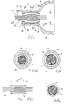
- a group of electric wires w comprise a wire harness W/H. Silicone 10, functioning as a sealant, is applied to a portion of this wire harness W/H where it passes through a narrow diameter cylindrical member 6a of a black grommet 6. An outer circumference of this silicone-coated portion 11 is covered with a closed cell urethane sheet 12. Openings at both ends of this urethane sheet 12 are bound tightly by yellow tape 13 and 14 made from vinyl chloride.
- an end of the urethane sheet 12 is positioned at a location corresponding to an end opening 6c of the narrow diameter cylindrical member 6a of the grommet 6 and the tape 13 is attached.
- the tape 14 is attached to the other end thereof.
- the end opening 6c of the narrow diameter cylindrical member 6a of the grommet is positioned to correspond to an inner edge of the tape 13.
- the position of the other end of the urethane sheet 12 corresponds to an end 6e of the narrow diameter cylindrical member.
- This end 6e of the narrow diameter cylindrical member joins with a wide diameter member 6d of the grommet.
- a tape 15 is would around both a tape-winding protrusion 6f which extends from a portion of the end opening 6c and the electric wires w, thereby fixing the grommet 6 and the electric wires w of the wire harness.
- the grommet 6 is attached to the wire harness W/H, and the silicone-coated portion 11, to which the silicone 10 has been applied and around which the urethane sheet 12 has been wrapped, fits tightly with the narrow diameter cylindrical member 6a of the grommet.
- the diameter of the narrow diameter cylindrical member 6a is less than the diameter of the electric wires w and so the narrow diameter cylindrical member 6a fits closely with the urethane sheet 12, and ribs 6b within the narrow diameter cylindrical member 6a press into this urethane sheet 12.
- the silicone 10 which fills the interior of the urethane sheet 12 is encouraged to penetrate in a length-wise direction X of the electric wires. Both ends, in a length-wise direction, of the urethane sheet 12 are however tightly bound by the tape 13 and 14.
- This tape 13 and 14 prevents the silicone 10 from escaping to the exterior and consequently, the silicone 10 penetrates into the cross-sectionally central direction Y of the electric wires w of the wire harness.
- the silicone 10 will penetrate into these unfilled portions, and thus the harness will be reliably sealed.
- the configuration is such that the closed cell urethane sheet 12 is wrapped around the wire harness, and both ends thereof are bound with the tape 13 and 14 until they are fixed. This prevents the sealant from escaping to the exterior, and the sealant can be forced to permeate into the centre of the wire harness.
- the sealant is prevented from escaping to the exterior by binding, the operability and external appearance are improved. Furthermore, the attachment position of the grommet can be made more accurate due to the position of the tape, which can be of any contrasting colour with respect to the grommet.
Abstract
Description
- The present invention relates to a configuration and method for water-proofing a wire harness passing through a grommet installed in a panel through hole of an automobile.
- In the case where a wire harness passes through a panel which divides an engine compartment and the interior of an automobile, a grommet made from rubber or elastomer is installed in a through hole passing through the panel. The wire harness passes through this grommet, and water etc. is thereby prevented from entering the interior.
- An outer circumference of a wide diameter member of the grommet has a panel engaging groove provided thereon. This groove engages an inner circumference edge of the panel through hole and the space between the grommet and the panel through hole is thus reliably sealed against moisture. A narrow diameter member of the grommet tightly receives the wire harness. The narrow diameter member is usually provided on the engine compartment side and prevents water etc. from entering the grommet.
- However, if spaces exist between electric wires of the wire harness and between the wire harness and the grommet, water may pass from the engine side to the interior. Various measures have been used in the past to deal with this, such as filling the grommet with a sealant, etc.
- The present inventor has previously provided the simple process of coating the electric wire spaces with a water-proofing material while the wire harness is on the assembly table, as described in JP-10-135657. As Figures 6-8 of this application show, in this method, on an assembly table 1, a
jig 2 formed on a wire harness path is provided with a pair of electric wire supports 2a and 2b. A group of electric wires w comprising a wire harness W/H are singulated and pass through these electric wire supports 2a and 2b. While the electric wires w are supported in an aligned manner by the electric wire supports 2a and 2b, a viscous ornon-liquid sealant 4 comprising silicone or the like is applied by anozzle 3 or a brush to the electric wires w. Then, as shown in Figures 9 and 10, the outer circumference of the part coated with thesealant 4 is wrapped in a closedcell foam sheet 5 or a film so as to form a circular shape, and in this state the harness is passed through agrommet 6. Then an open end of a narrow diametercylindrical member 6a of thegrommet 6 is fixed to thesheet 5 withtape 7. - The above method has the advantage of being performed on a wire harness assembly table, on the wire harness assembly line. However, as shown in Figure 11, in the case where a portion of the electric wires w supported in an aligned manner by the electric wire supports 2a and 2b crosses and becomes twisted, a space C occurs. The
sealant 4 does not fill this space C and an uncovered portion C' will remain. Consequently, as shown in Figure 12, even though the electric wires w are covered by thesheet 5 and are formed into a circular shape, the space C may not be filled with thesealant 4 due to the high viscosity thereof. - As shown in Figure 13, the filled portion is next fastened along the narrow diameter
cylindrical member 6a of thegrommet 6 and thesealant 4 is urged into the portion C'. However, the movement of thesealant 4 in a length-wise direction X of the electric wires is greater than the penetration of thesealant 4 in a cross-sectionally central direction Y of the wire harness. Consequently, if the central portion of the electric wires of the wire harness has the uncovered portion C', thesealant 4 often does not penetrate into that portion and merely passes along the length-wise direction of the electric wires. As a result, the uncovered portion C' will remain unsealed. - The present invention has been developed after taking the above problem into consideration, and aims to prevent the sealant from passing along the length-wise direction of electric wires, instead causing the sealant to penetrate in the cross-sectionally central direction of the wire harness, this invention reliably preventing portions from remaining unfilled with sealant.
- According to the invention there is provided a method of sealing a wire harness in a grommet against the passage of moisture, the method comprising the steps of:
- a) collating a bundle of wires;
- b) coating the exterior of a predetermined length of said bundle with a viscous sealant;
- c) wrapping said bundle with a sheet so as to cover said predetermined length and end portions on either side thereof;
- d) tightly binding said end portions to confine said sealant and prevent escape thereof; and
- e) inserting said predetermined length of said bundle into a tight fitting grommet of resilient material, such that the sealant is forced to permeate throughout said bundle.
-
- Such a method both confines the sealant, and places it under resilient loading within the grommet. In this way permeation of the sealant throughout the bundle can be assured.
- Preferably the end portions are bound with adhesive tape, which may be a contrasting colour in order to ensure correct relative location of grommet and wire harness. The harness and grommet may subsequently be bound together, for example by utilising a projection of the grommet extending along the length of the wire bundle. The grommet may include internal projections, preferably annular, to apply circumferential pressure to the wire bundle at specified locations.
- Other features of the invention will be apparent from the following description of a preferred embodiment shown by way of example in the accompanying drawings in which:
- Figure 1 is a cross-sectional view through an embodiment of the invention;
- Figure 2 is a cross-section of Fig. 1 on line 2-2;
- Figure 3 is a cross-section of Fig. 1 on line 3-3;
- Figure 4 is a cross-sectional view showing a state whereby a group of electric wires are filled with silicone, a sheet being attached and bound with tape;
- Figure 5 is a cross-sectional view of Fig.4 on line 5-5;
- Figure 6 is a diagonal view showing a conventional example;
- Figures 7 and 8 illustrate the method of the conventional example;
- Figure 9 is a cross-sectional view of the conventional example;
- Figure 10 is a plan view showing sealant is applied to the conventional example; and
- Figures 11-13 illustrate the conventional example.
-
- An embodiment of the present invention is described below with the aid of Figures 1-5. A group of electric wires w comprise a wire harness W/
H. Silicone 10, functioning as a sealant, is applied to a portion of this wire harness W/H where it passes through a narrow diametercylindrical member 6a of ablack grommet 6. An outer circumference of this silicone-coatedportion 11 is covered with a closedcell urethane sheet 12. Openings at both ends of thisurethane sheet 12 are bound tightly byyellow tape - As shown in Figures 4 and 5, an end of the
urethane sheet 12 is positioned at a location corresponding to an end opening 6c of the narrow diametercylindrical member 6a of thegrommet 6 and thetape 13 is attached. Thetape 14 is attached to the other end thereof. The end opening 6c of the narrow diametercylindrical member 6a of the grommet is positioned to correspond to an inner edge of thetape 13. In this state, the position of the other end of theurethane sheet 12 corresponds to anend 6e of the narrow diameter cylindrical member. Thisend 6e of the narrow diameter cylindrical member joins with awide diameter member 6d of the grommet. - After the position of the inner edge of the
tape 13 is made to correspond to the end opening 6c of the narrow diametercylindrical member 6a of thegrommet 6, atape 15 is would around both a tape-windingprotrusion 6f which extends from a portion of the end opening 6c and the electric wires w, thereby fixing thegrommet 6 and the electric wires w of the wire harness. - In this manner, the
grommet 6 is attached to the wire harness W/H, and the silicone-coatedportion 11, to which thesilicone 10 has been applied and around which theurethane sheet 12 has been wrapped, fits tightly with the narrow diametercylindrical member 6a of the grommet. The diameter of the narrow diametercylindrical member 6a is less than the diameter of the electric wires w and so the narrow diametercylindrical member 6a fits closely with theurethane sheet 12, and ribs 6b within the narrow diametercylindrical member 6a press into thisurethane sheet 12. - As a result, the
silicone 10 which fills the interior of theurethane sheet 12 is encouraged to penetrate in a length-wise direction X of the electric wires. Both ends, in a length-wise direction, of theurethane sheet 12 are however tightly bound by thetape tape silicone 10 from escaping to the exterior and consequently, thesilicone 10 penetrates into the cross-sectionally central direction Y of the electric wires w of the wire harness. As a result, if portions among the electric wires w remain unfilled, thesilicone 10 will penetrate into these unfilled portions, and thus the harness will be reliably sealed. - As shown in Figures 4 and 5, the configuration is such that the closed
cell urethane sheet 12 is wrapped around the wire harness, and both ends thereof are bound with thetape - Moreover, since the sealant is prevented from escaping to the exterior by binding, the operability and external appearance are improved. Furthermore, the attachment position of the grommet can be made more accurate due to the position of the tape, which can be of any contrasting colour with respect to the grommet.
Claims (10)
- A method of sealing a wire harness (W/H) in a grommet (6) against the passage of moisture, the method comprising the steps of:a) collating a bundle of wires (W);b) coating the exterior of a predetermined length of said bundle with a viscous sealant (10);c) wrapping said bundle with a sheet (12) so as to cover said predetermined length and end portions on either side thereof;d) tightly binding said end portions to confine said sealant and prevent escape thereof; ande) inserting said predetermined length of said bundle into a tight fitting grommet (6) of resilient material, such that the sealant is forced to permeate throughout said bundle.
- A method according to claim 1 including the step of aligning one of said end portions with a feature of said grommet.
- A method according to claim 2 including the step of aligning one of said end portions with an end of said grommet.
- A method according to claim 2 including the step of aligning one of said end portions with a change of section of said grommet.
- A method according to any preceding claim including the step of tightly binding said end portions with adhesive tape (13).
- A method according to claim 5 including the step of selecting an adhesive tape of a contrasting colour to said grommet.
- A method according to claim 5 or claim 6 including the step of selecting an adhesive tape of a contrasting colour to said sheet.
- A method according to any preceding claim and including a final step of:
f) binding said grommet to said bundle of wires. - A method according to any preceding claim including the steps of selecting a viscous sealant of silicone, and a sheet of closed cell urethane.
- A wire harness and grommet assembly made according to the method of any of claims 1-9.
Applications Claiming Priority (2)
| Application Number | Priority Date | Filing Date | Title |
|---|---|---|---|
| JP847999 | 1999-01-14 | ||
| JP00847999A JP3417324B2 (en) | 1999-01-14 | 1999-01-14 | Waterproof structure and waterproofing method of grommet mounting part of wire harness |
Publications (3)
| Publication Number | Publication Date |
|---|---|
| EP1020971A2 true EP1020971A2 (en) | 2000-07-19 |
| EP1020971A3 EP1020971A3 (en) | 2000-11-15 |
| EP1020971B1 EP1020971B1 (en) | 2009-09-30 |
Family
ID=11694257
Family Applications (1)
| Application Number | Title | Priority Date | Filing Date |
|---|---|---|---|
| EP99310236A Expired - Lifetime EP1020971B1 (en) | 1999-01-14 | 1999-12-20 | Waterproofing arrangement for wire harness |
Country Status (5)
| Country | Link |
|---|---|
| US (1) | US6438828B1 (en) |
| EP (1) | EP1020971B1 (en) |
| JP (1) | JP3417324B2 (en) |
| CN (1) | CN1147042C (en) |
| DE (1) | DE69941477D1 (en) |
Cited By (3)
| Publication number | Priority date | Publication date | Assignee | Title |
|---|---|---|---|---|
| DE10140714A1 (en) * | 2001-08-24 | 2003-03-13 | Woco Franz Josef Wolf & Co Gmbh | Grommet for leading cable through a wall has shaft with tightening lip of softer material than the holder |
| DE102004009888A1 (en) * | 2004-02-26 | 2005-09-15 | Valeo Wischersysteme Gmbh | Entry arrangement for heater wires of a vehicle windscreen washing unit comprises sealing elements obtained by filling at least a part of the entry opening with a hardenable sealing compound |
| US20230245801A1 (en) * | 2020-08-13 | 2023-08-03 | Auto-Kabel Management Gmbh | Gasket for an Electric Cable |
Families Citing this family (37)
| Publication number | Priority date | Publication date | Assignee | Title |
|---|---|---|---|---|
| JP3501023B2 (en) * | 1999-07-06 | 2004-02-23 | 住友電装株式会社 | Waterproofing method for wire assembly and sealant application device used therefor |
| JP3692969B2 (en) * | 2001-06-08 | 2005-09-07 | 住友電装株式会社 | Grommet line sealing method |
| SE520363C2 (en) * | 2001-12-14 | 2003-07-01 | Roxtec Int Ab | Entry device for conducting elongated conduit through an opening in a wall |
| JP4374187B2 (en) * | 2002-12-20 | 2009-12-02 | 矢崎総業株式会社 | Connection method between terminal and coated wire |
| JP4196762B2 (en) * | 2003-07-29 | 2008-12-17 | 住友電装株式会社 | Water stop method for wire harness |
| JP4064321B2 (en) * | 2003-08-25 | 2008-03-19 | 矢崎総業株式会社 | Method for forming waterstop part of wire harness |
| JP4118769B2 (en) * | 2003-09-03 | 2008-07-16 | 矢崎総業株式会社 | Water stop treatment method for wire harness and wire harness |
| DE102005022937B4 (en) * | 2005-05-19 | 2013-11-07 | Volkswagen Ag | Method for producing a longitudinally watertight arrangement of a cable strand in an elastic grommet |
| JP4293206B2 (en) * | 2005-08-10 | 2009-07-08 | ソニー株式会社 | Wire harness, lighting device, backlight device, and liquid crystal display device |
| US20080066949A1 (en) * | 2006-09-15 | 2008-03-20 | Preformed Line Products Company | Sealing grommet |
| JP5264081B2 (en) * | 2007-01-29 | 2013-08-14 | 矢崎総業株式会社 | Line water-stop method and line water-stop device |
| JP5191178B2 (en) * | 2007-07-04 | 2013-04-24 | 矢崎総業株式会社 | Grommet |
| JP5179794B2 (en) * | 2007-08-01 | 2013-04-10 | 矢崎総業株式会社 | Waterproof structure between wires |
| JP4924388B2 (en) * | 2007-11-30 | 2012-04-25 | 住友電装株式会社 | Grommet waterproof method and waterproof structure |
| CN101285694B (en) * | 2008-05-13 | 2010-06-02 | 华中科技大学 | Seal device for multi-sensor wired measuring |
| FR2931312B1 (en) * | 2008-05-16 | 2010-09-03 | Thales Sa | SEALED THREAD AND METHOD OF MAKING THE WIRE PASS |
| DE102010028592B4 (en) * | 2010-05-05 | 2014-11-13 | Lisa Dräxlmaier GmbH | Grommet and method of making such a grommet |
| CN102412010B (en) * | 2010-09-21 | 2015-06-10 | 易鼎股份有限公司 | A waterproof structure of bunchy flexible flat cable |
| JP5760659B2 (en) * | 2011-05-06 | 2015-08-12 | 住友電装株式会社 | Grommet |
| JP5736963B2 (en) * | 2011-05-26 | 2015-06-17 | 住友電装株式会社 | Grommet |
| JP5844572B2 (en) * | 2011-08-08 | 2016-01-20 | 矢崎総業株式会社 | Wire harness water stop structure and wire harness |
| JP2013097922A (en) | 2011-10-28 | 2013-05-20 | Yazaki Corp | Core wire waterproofing structure and core wire waterproofing method |
| JP5874977B2 (en) * | 2012-09-18 | 2016-03-02 | 住友電装株式会社 | Grommet and mounting member with grommet |
| JP5929839B2 (en) | 2013-05-30 | 2016-06-08 | 住友電装株式会社 | Waterproof sheet for wire harness and waterproof structure of wire harness |
| CN103366878B (en) * | 2013-07-03 | 2015-10-21 | 株洲南车时代电气股份有限公司 | A kind of water-proof wire bundle and preparation method thereof |
| JP5918183B2 (en) * | 2013-09-05 | 2016-05-18 | トヨタ自動車株式会社 | Cable harness and water stop structure |
| DE102015220318A1 (en) * | 2015-10-19 | 2017-04-20 | Lisa Dräxlmaier GmbH | DOZEN AND METHOD FOR MANUFACTURING SUCH A PIECE |
| CN106099793A (en) * | 2016-07-28 | 2016-11-09 | 中车长春轨道客车股份有限公司 | Cable-through hole wire harness method for blocking |
| JP6642409B2 (en) * | 2016-12-19 | 2020-02-05 | 住友電装株式会社 | Structure for holding protective member in wire harness |
| JP6574803B2 (en) * | 2017-03-27 | 2019-09-11 | 矢崎総業株式会社 | Waterproof parts |
| CN107039125A (en) * | 2017-06-01 | 2017-08-11 | 芜湖侨云友星电气工业有限公司 | A kind of preparation method of waterproof anti-corrosion wire harness |
| JP6841175B2 (en) | 2017-07-03 | 2021-03-10 | 住友電装株式会社 | Water-stop structure for wire bundles |
| JP2019054642A (en) * | 2017-09-15 | 2019-04-04 | 本田技研工業株式会社 | Power distribution branch unit and vehicle |
| JP6518299B2 (en) * | 2017-09-20 | 2019-05-22 | 株式会社オートネットワーク技術研究所 | Wire Harness |
| JP6613282B2 (en) * | 2017-10-26 | 2019-11-27 | 矢崎総業株式会社 | Grommet and grommet assembly method |
| US11217978B2 (en) | 2019-03-29 | 2022-01-04 | Yazaki North America, Inc. | Anti-slip system with overmold operation |
| US11515064B2 (en) | 2019-04-01 | 2022-11-29 | Yazaki North America, Inc. | Anti-slip system with injection operation |
Citations (3)
| Publication number | Priority date | Publication date | Assignee | Title |
|---|---|---|---|---|
| EP0320891A2 (en) * | 1987-12-17 | 1989-06-21 | Delphi Automotive Systems Deutschland GmbH | Water-tight cable feedthrough or inlet, its manufacturing process and manufacture process of a longitudinally water-tight transmission bundle in a device |
| DE3903059A1 (en) * | 1989-02-02 | 1990-08-09 | Minnesota Mining & Mfg | Method and device for sealing a cable bundle in the longitudinal direction |
| US5270487A (en) * | 1991-08-30 | 1993-12-14 | Sumitomo Wiring Systems, Ltd. | Grommet |
Family Cites Families (15)
| Publication number | Priority date | Publication date | Assignee | Title |
|---|---|---|---|---|
| US4020546A (en) * | 1975-03-26 | 1977-05-03 | Consolidation Coal Company | Method for making a cable splice joining a pair of flexible conducting cables |
| US4928349A (en) * | 1987-07-15 | 1990-05-29 | Yazaki Corporation | Grommet structure |
| US4797513A (en) * | 1987-11-25 | 1989-01-10 | Yazaki Corporation | Grommet with wires sealed thereto and method of forming same |
| US5217808A (en) * | 1989-11-29 | 1993-06-08 | At&T Bell Laboratories | Water blocked cable portion and methods of making same |
| JP2891059B2 (en) * | 1993-10-04 | 1999-05-17 | 住友電装株式会社 | Wire harness waterproof structure |
| JPH07228208A (en) * | 1994-02-17 | 1995-08-29 | Sumitomo Wiring Syst Ltd | Grommet |
| JPH07245030A (en) * | 1994-03-07 | 1995-09-19 | Sumitomo Wiring Syst Ltd | Grommet |
| JP3156823B2 (en) | 1994-10-14 | 2001-04-16 | 矢崎総業株式会社 | Water stopping structure of wire harness and method of stopping water |
| JPH09233652A (en) | 1996-02-21 | 1997-09-05 | Sumitomo Wiring Syst Ltd | Structure and method for waterproofing of grommet |
| US6225562B1 (en) * | 1996-04-26 | 2001-05-01 | Sumitomo Wiring Systems, Ltd. | Sealant for filling grommet, method for sealing a wire harness using the sealant and sealing structure |
| JP3487097B2 (en) | 1996-09-03 | 2004-01-13 | 住友電装株式会社 | Wire harness waterproofing method and waterproofing jig used in the method |
| JP3252729B2 (en) * | 1996-12-10 | 2002-02-04 | 住友電装株式会社 | Waterproofing method of wire harness and waterproofing agent discharger used therefor |
| JP3198962B2 (en) | 1997-02-13 | 2001-08-13 | 住友電装株式会社 | Method of forming grommet waterproof structure through wire harness |
| JP3901286B2 (en) * | 1997-06-17 | 2007-04-04 | 矢崎総業株式会社 | Winding method and winding jig for wire protection member |
| JP3629989B2 (en) * | 1998-11-30 | 2005-03-16 | 住友電装株式会社 | Grommet line sealing method and grommet line sealing structure |
-
1999
- 1999-01-14 JP JP00847999A patent/JP3417324B2/en not_active Expired - Lifetime
- 1999-12-20 EP EP99310236A patent/EP1020971B1/en not_active Expired - Lifetime
- 1999-12-20 DE DE69941477T patent/DE69941477D1/en not_active Expired - Lifetime
-
2000
- 2000-01-11 US US09/480,256 patent/US6438828B1/en not_active Expired - Lifetime
- 2000-01-14 CN CNB001003097A patent/CN1147042C/en not_active Expired - Lifetime
Patent Citations (3)
| Publication number | Priority date | Publication date | Assignee | Title |
|---|---|---|---|---|
| EP0320891A2 (en) * | 1987-12-17 | 1989-06-21 | Delphi Automotive Systems Deutschland GmbH | Water-tight cable feedthrough or inlet, its manufacturing process and manufacture process of a longitudinally water-tight transmission bundle in a device |
| DE3903059A1 (en) * | 1989-02-02 | 1990-08-09 | Minnesota Mining & Mfg | Method and device for sealing a cable bundle in the longitudinal direction |
| US5270487A (en) * | 1991-08-30 | 1993-12-14 | Sumitomo Wiring Systems, Ltd. | Grommet |
Cited By (6)
| Publication number | Priority date | Publication date | Assignee | Title |
|---|---|---|---|---|
| DE10140714A1 (en) * | 2001-08-24 | 2003-03-13 | Woco Franz Josef Wolf & Co Gmbh | Grommet for leading cable through a wall has shaft with tightening lip of softer material than the holder |
| DE10140714C2 (en) * | 2001-08-24 | 2003-08-14 | Woco Franz Josef Wolf & Co Gmbh | grommet |
| DE102004009888A1 (en) * | 2004-02-26 | 2005-09-15 | Valeo Wischersysteme Gmbh | Entry arrangement for heater wires of a vehicle windscreen washing unit comprises sealing elements obtained by filling at least a part of the entry opening with a hardenable sealing compound |
| DE102004009888B4 (en) * | 2004-02-26 | 2021-01-28 | Valeo Wischersysteme Gmbh | Heat conductor feed-through for a windscreen washer system and a windscreen washer system |
| US20230245801A1 (en) * | 2020-08-13 | 2023-08-03 | Auto-Kabel Management Gmbh | Gasket for an Electric Cable |
| US11881331B2 (en) * | 2020-08-13 | 2024-01-23 | Auto-Kabel Management Gmbh | Gasket for an electric cable |
Also Published As
| Publication number | Publication date |
|---|---|
| DE69941477D1 (en) | 2009-11-12 |
| CN1260620A (en) | 2000-07-19 |
| EP1020971B1 (en) | 2009-09-30 |
| JP2000209749A (en) | 2000-07-28 |
| US6438828B1 (en) | 2002-08-27 |
| CN1147042C (en) | 2004-04-21 |
| JP3417324B2 (en) | 2003-06-16 |
| EP1020971A3 (en) | 2000-11-15 |
Similar Documents
| Publication | Publication Date | Title |
|---|---|---|
| EP1020971B1 (en) | Waterproofing arrangement for wire harness | |
| US6010134A (en) | Sealed grommet for wire harnesses having a split cylindrical core member with a complementary grommet sleeve | |
| JP2947000B2 (en) | Wire harness waterproofing method and waterproofing structure | |
| US5536904A (en) | Waterproof construction of wire | |
| US5270487A (en) | Grommet | |
| US6312046B1 (en) | Grommet and fixing structure thereof | |
| US20070209821A1 (en) | Waterproof Structure And Waterproof Method For Wire Connecting Part | |
| US8579240B2 (en) | Sealing tie clip that holds an object and prevents lateral movement thereto | |
| JPH1186840A (en) | Connection tool for battery | |
| JP2003018727A (en) | Clamp for corrugated tube for wiring harness | |
| JP3002941B2 (en) | Grommet | |
| JPH08335419A (en) | Grommet installation structure | |
| JP2000341841A (en) | Method and structure for cutting off water for electric cable terminal connecting part | |
| JP3116837B2 (en) | Grommet waterproof structure and waterproofing method | |
| JP5074893B2 (en) | Water stop member, wire harness having the water stop member, and water stop forming method using the water stop member | |
| IE44057B1 (en) | Method and device for enclosing a cable splice | |
| JP3156823B2 (en) | Water stopping structure of wire harness and method of stopping water | |
| JP3379447B2 (en) | Grommet spacer and grommet provided with the spacer | |
| EP3819172A1 (en) | Wire harness | |
| JP2003047137A (en) | Grommet | |
| JP2004187354A (en) | Grommet | |
| JPH0739046A (en) | Water-stopping method of wire harness | |
| JP3039856U (en) | Grommets and equipment with grommets | |
| JPH0898374A (en) | Forming method for water-proof block in wire harness | |
| JPH0946862A (en) | Grommet spacer and moisture-proof structure of grommet using the spacer |
Legal Events
| Date | Code | Title | Description |
|---|---|---|---|
| PUAI | Public reference made under article 153(3) epc to a published international application that has entered the european phase |
Free format text: ORIGINAL CODE: 0009012 |
|
| 17P | Request for examination filed |
Effective date: 20000113 |
|
| AK | Designated contracting states |
Kind code of ref document: A2 Designated state(s): DE FR GB |
|
| AX | Request for extension of the european patent |
Free format text: AL;LT;LV;MK;RO;SI |
|
| PUAL | Search report despatched |
Free format text: ORIGINAL CODE: 0009013 |
|
| AK | Designated contracting states |
Kind code of ref document: A3 Designated state(s): AT BE CH CY DE DK ES FI FR GB GR IE IT LI LU MC NL PT SE |
|
| AX | Request for extension of the european patent |
Free format text: AL;LT;LV;MK;RO;SI |
|
| AKX | Designation fees paid |
Free format text: DE FR GB |
|
| 17Q | First examination report despatched |
Effective date: 20081001 |
|
| GRAP | Despatch of communication of intention to grant a patent |
Free format text: ORIGINAL CODE: EPIDOSNIGR1 |
|
| RIN1 | Information on inventor provided before grant (corrected) |
Inventor name: UCHIYAMA, KENICHI |
|
| GRAS | Grant fee paid |
Free format text: ORIGINAL CODE: EPIDOSNIGR3 |
|
| GRAA | (expected) grant |
Free format text: ORIGINAL CODE: 0009210 |
|
| AK | Designated contracting states |
Kind code of ref document: B1 Designated state(s): DE FR GB |
|
| REG | Reference to a national code |
Ref country code: GB Ref legal event code: FG4D |
|
| REF | Corresponds to: |
Ref document number: 69941477 Country of ref document: DE Date of ref document: 20091112 Kind code of ref document: P |
|
| PLBE | No opposition filed within time limit |
Free format text: ORIGINAL CODE: 0009261 |
|
| STAA | Information on the status of an ep patent application or granted ep patent |
Free format text: STATUS: NO OPPOSITION FILED WITHIN TIME LIMIT |
|
| 26N | No opposition filed |
Effective date: 20100701 |
|
| PGFP | Annual fee paid to national office [announced via postgrant information from national office to epo] |
Ref country code: DE Payment date: 20131218 Year of fee payment: 15 Ref country code: GB Payment date: 20131218 Year of fee payment: 15 |
|
| PGFP | Annual fee paid to national office [announced via postgrant information from national office to epo] |
Ref country code: FR Payment date: 20131209 Year of fee payment: 15 |
|
| REG | Reference to a national code |
Ref country code: DE Ref legal event code: R119 Ref document number: 69941477 Country of ref document: DE |
|
| GBPC | Gb: european patent ceased through non-payment of renewal fee |
Effective date: 20141220 |
|
| REG | Reference to a national code |
Ref country code: FR Ref legal event code: ST Effective date: 20150831 |
|
| PG25 | Lapsed in a contracting state [announced via postgrant information from national office to epo] |
Ref country code: DE Free format text: LAPSE BECAUSE OF NON-PAYMENT OF DUE FEES Effective date: 20150701 Ref country code: GB Free format text: LAPSE BECAUSE OF NON-PAYMENT OF DUE FEES Effective date: 20141220 |
|
| PG25 | Lapsed in a contracting state [announced via postgrant information from national office to epo] |
Ref country code: FR Free format text: LAPSE BECAUSE OF NON-PAYMENT OF DUE FEES Effective date: 20141231 |