EP1008693A1 - Construction machine - Google Patents
Construction machine Download PDFInfo
- Publication number
- EP1008693A1 EP1008693A1 EP98919524A EP98919524A EP1008693A1 EP 1008693 A1 EP1008693 A1 EP 1008693A1 EP 98919524 A EP98919524 A EP 98919524A EP 98919524 A EP98919524 A EP 98919524A EP 1008693 A1 EP1008693 A1 EP 1008693A1
- Authority
- EP
- European Patent Office
- Prior art keywords
- operating unit
- base platform
- cab
- construction machine
- traveling truck
- Prior art date
- Legal status (The legal status is an assumption and is not a legal conclusion. Google has not performed a legal analysis and makes no representation as to the accuracy of the status listed.)
- Withdrawn
Links
Images


Classifications
-
- E—FIXED CONSTRUCTIONS
- E02—HYDRAULIC ENGINEERING; FOUNDATIONS; SOIL SHIFTING
- E02F—DREDGING; SOIL-SHIFTING
- E02F9/00—Component parts of dredgers or soil-shifting machines, not restricted to one of the kinds covered by groups E02F3/00 - E02F7/00
- E02F9/08—Superstructures; Supports for superstructures
- E02F9/0808—Improving mounting or assembling, e.g. frame elements, disposition of all the components on the superstructures
-
- E—FIXED CONSTRUCTIONS
- E02—HYDRAULIC ENGINEERING; FOUNDATIONS; SOIL SHIFTING
- E02F—DREDGING; SOIL-SHIFTING
- E02F3/00—Dredgers; Soil-shifting machines
- E02F3/04—Dredgers; Soil-shifting machines mechanically-driven
- E02F3/28—Dredgers; Soil-shifting machines mechanically-driven with digging tools mounted on a dipper- or bucket-arm, i.e. there is either one arm or a pair of arms, e.g. dippers, buckets
- E02F3/30—Dredgers; Soil-shifting machines mechanically-driven with digging tools mounted on a dipper- or bucket-arm, i.e. there is either one arm or a pair of arms, e.g. dippers, buckets with a dipper-arm pivoted on a cantilever beam, i.e. boom
- E02F3/32—Dredgers; Soil-shifting machines mechanically-driven with digging tools mounted on a dipper- or bucket-arm, i.e. there is either one arm or a pair of arms, e.g. dippers, buckets with a dipper-arm pivoted on a cantilever beam, i.e. boom working downwardly and towards the machine, e.g. with backhoes
- E02F3/325—Backhoes of the miniature type
-
- E—FIXED CONSTRUCTIONS
- E02—HYDRAULIC ENGINEERING; FOUNDATIONS; SOIL SHIFTING
- E02F—DREDGING; SOIL-SHIFTING
- E02F3/00—Dredgers; Soil-shifting machines
- E02F3/04—Dredgers; Soil-shifting machines mechanically-driven
- E02F3/96—Dredgers; Soil-shifting machines mechanically-driven with arrangements for alternate or simultaneous use of different digging elements
- E02F3/963—Arrangements on backhoes for alternate use of different tools
- E02F3/964—Arrangements on backhoes for alternate use of different tools of several tools mounted on one machine
-
- E—FIXED CONSTRUCTIONS
- E02—HYDRAULIC ENGINEERING; FOUNDATIONS; SOIL SHIFTING
- E02F—DREDGING; SOIL-SHIFTING
- E02F9/00—Component parts of dredgers or soil-shifting machines, not restricted to one of the kinds covered by groups E02F3/00 - E02F7/00
- E02F9/16—Cabins, platforms, or the like, for drivers
Definitions
- the present invention relates to the structure of a construction machine for performing construction work, and the like, by means of a first operating unit and a second operating unit, which travels by means of a traveling truck.
- Figs. 4(a), (b) illustrate a construction machine for performing construction work equipped with a first and a second operating unit, where Fig. 4(a) is a plan view and Fig. 4(b) is a side view.
- this construction machine is provided with a back hoe 52, which is an excavating and earth-moving tool, in the rear area of the traveling truck 51, and a loader 54 which is loading tool, in the front area of the traveling truck 51.
- the back hoe 52 is supported by a first base platform 53, such that it is capable of upward and downward movement, and the first base platform 53 is capable of rotating 360° in a horizontal direction by turning within the range of the circle 55 indicated by the broken line in the diagram, when the back hoe 52 is in a retracted state.
- the back hoe 52 is an excavating tool consisting of an excavating bucket and a multiple-jointed arm.
- the loader 54 is a loading tool consisting of arms and a bucket installed at the end of these arms, the bases of the loader 54 being installed on attachment members 58, such that it is capable of upward and downward movement.
- the first base platform 53 supporting the back hoe 52 is fixed to a rotating unit 56, and is capable of rotating about an axis of rotation 57. Furthermore, the loader 54 is installed on the attachment members 58 in such a manner that it does not interfere with the first base platform 53, when the first base platform 53 rotates.
- the loader 54 will not be capable of a large reach, and hence it will not be able to provide a broad operating range. In other words, a new problem will arise in that working efficiency will decline.
- the present invention was devised with the foregoing in view, an object thereof being to provide a construction machine whereby the overall length of the machine can be shortened compared to a conventional construction machine, in such a manner that the machine is suitable for use in restricted spaces, whilst making it possible to achieve a broad operating range and to increase working efficiency.
- the present invention is a construction machine wherein a first base platform supporting a first operating unit is provided rotatably in a horizontal direction on an upper portion of a traveling truck, and a second operating unit is also provided on the upper portion of the traveling truck, characterized in that:
- a second operating unit 14 is installed on the upper part of a traveling truck 11 in such a manner that the bases 14a of the second operating unit 14 are positioned within areas 1d, 1e (diagonally shaded areas) in the vicinity of the swiveling circle 1a of the first base platform 13, to the outside thereof, extending between a tangent 1b to the swiveling circle 1a running in parallel to the widthwise direction of the traveling truck 11 and a straight line 1c passing through the center of the swiveling circle 1a and running in parallel with the widthwise direction of the traveling truck 11.
- the position of the second operating unit 14 can be moved further towards the inner portion of the vehicle compared to the position of a conventional second operating unit 15 (as depicted by the broken lines), and hence the overall vehicle length can be reduced without shortening the arms of the second operating unit 14.
- the construction machine according to the present invention has a shorter overall vehicle length than a conventional construction machine, and it is therefore suitable for use in restricted spaces. Moreover, since it is not necessary to reduce the length of the arms of the second operating unit 14, the second operating unit 14 is able to provide a large reach, thereby improving working efficiency.
- Fig. 1(a) is a side view of a construction machine according to an embodiment of the present invention
- Fig. 1(b) is a plan view of same.
- traveling truck 11 is a vehicle having a travelling function, which, for example, uses a caterpillar tread system, as shown in the drawings. Moreover, the vehicle may also be based on a wheel system, as illustrated in Fig. 4(a) and (b). The present embodiment is based on the presumption of a construction machine having an ultra-small swiveling circle, wherein the swiveling circle 1a of the first base platform 13 is restricted within the width of the traveling truck 11.
- the first base platform 13 is a cab in which an operator rides.
- a rotating unit 17 which rotates freely through 360° in a horizontal direction about a rotational axis 16 is installed on the upper part of the traveling truck 11, and the first base platform 13 is fixed to this rotating unit 17.
- a back hoe 12 forming a first operating unit is supported on the end portion of this base platform 13. Therefore, by operating the rotating unit 17 appropriately, the back hoe 12 can be positioned in any chosen direction in the horizontal plane.
- a loader 14 forming a second operating unit is also installed on the upper part of the traveling truck 11.
- the bases of this loader 14 are supported by attachment members 18 provided on the side faces of the first base platform 13.
- the attachment members 18 are fixed to a frame 19 positioned below the first base platform 13, and this frame 19 is fixed to the traveling truck 11.
- the loader 14 is installed on the attachment members 18 on the upper part of the traveling truck 11 in such a manner that the bases 14a, which are the sections where the loader 14 is connected to the attachment members 18, are located within areas 1d, 1e (indicated by diagonal shading) which lie in the vicinity of the swiveling circle 1a of the first base platform 13, to the outside thereof, extending between tangent 1b of the aforementioned swiveling circle 1a running in parallel with the widthwise direction of the traveling truck 11, and straight line 1c passing through the center of the aforementioned swiveling circle 1a and also running in parallel with the widthwise direction of the traveling truck 11.
- the bases 14a of the loader 14 are attached to attachment members 18 which are separate items from the frame 19, but it is also possible for the bases 14a of the loader 14 to be attached to attachment members formed integrally with the frame 19. In short, the bases 14a of the loader 14 should be attached to attachment members extending from a frame 19 provided between the traveling truck 11 and the first base platform 13.
- the bases 14a of the loader 14 may also be installed on attachment members extending from the traveling truck 11, without providing a frame 19 between the traveling truck 11 and the first base platform 13.
- the attachment members may be formed independently from the traveling truck 11, or they may be formed integrally with the traveling truck 11.
- the loader 14 forming the second operating unit may be installed in such a manner that it can rotate freely in a horizontal direction.
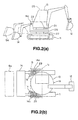
- Fig. 2(a) is a side view of an embodiment wherein a loader 14 is capable of rotating
- Fig. 2(b) is a plan view of same. Similar labels to Figs. 1(a) and (b) indicate the same parts.
- a rotating unit 27 which is capable of rotating freely through 360° in a horizontal direction about an axis of rotation 26 is installed on the upper part of a traveling truck 11, and a frame 28 is fixed to this rotating unit 27.
- Attachment members 29 for supporting the bases 14a of the loader 14 are installed on the aforementioned frame 28. Consequently, by operating the rotating unit 27 as necessary, it is possible to position the loader 14 in any direction in the horizontal plane.
- the frame 28 which supports the loader 14 by means of the attachment members 29 functions as a second base platform about which the loader 14 rotates.
- the bases 14a of the loader 14 are installed on attachment members 29 which are formed as independent units from the frame 28 representing the second base platform, but the bases 14a of the loader 14 may also be installed on attachment members which are formed integrally with the frame 28 representing the second base platform.
- the attachment members may fabricated integrally with, or independently from, the frame 28.
- a rotating unit 2a capable of rotating freely through 360° in a horizontal direction is installed on the upper part of the frame 28, and a first base platform 13 is fixed to this rotating unit 2a.
- a back hoe 12 forming a first operating unit is supported at the end portion of this first base platform 13. Consequently, by operating the rotating unit 2a in an appropriate manner, the back hoe 12 can be positioned in any direction in the horizontal plane.
- the axis of rotation of the rotating unit 2a which causes the first base platform 13 to turn may be set such that it is coaxial with the axis of rotation 26 of the rotating unit 27 which causes the frame 28 forming the second base platform to turn, or alternatively, these two axes of rotation may be offset from each other by an appropriate amount.
- the positional relationship between the loader 14 and the first base platform 13, as shown in Fig.2(b), is such that the bases 14a of the loader 14 are located within areas 1d, 1e lying close outside the swiveling circle 1a of the first base platform 13, similarly to Fig. 1(b).
- the loader forming the second operating unit comprises two arms, namely, a left and a right arm, but as shown in Fig. 3, the present invention may also be implemented in a construction machine comprising a loader 44 having only one arm.
- the base 44a of the loader 44 is located with a area 1e close outside the swiveling circle 1a of the first base platform 13.
- the bases 14a, 44a of the loader 14 or 44 are located within areas 1d, 1e (diagonally shaded areas) which lie in the vicinity of the swiveling circle 1a of the first base platform 13, to the outside thereof, extending between tangent 1b of the aforementioned swiveling circle 1a running in parallel with the widthwise direction of the traveling truck 11, and straight line 1c passing through the center of the aforementioned swiveling circle 1a and also running in parallel with the widthwise direction of the traveling truck 11, the position of the loader 14 or 44 can be moved towards the inner side of the vehicle compared to the position of a conventional loader 54 (indicated by broken lines in Fig. 1, Fig. 2 and Fig. 3), without giving rise to interference between the loader 14 or 44 and the first base platform 13. Consequently, the overall length of the vehicle can be shortened without reducing the length of the arms of the loader 14, 44.
- the overall vehicle length of the construction machine according to the present embodiments is shorter than that of a conventional construction machine, it is suitable for use in restricted spaces. Moreover, since it is not necessary to shorten the length of the arms of the loader 14, 44, it is possible to achieve a long reach for the loader 14, 44, and working efficiency can be improved.
- a frame 19, 28 covering the lower sides of the cab 13 is provided in addition to the attachment members 18, 29 installed on the side faces of the first base platform 13 formed by the cab, it is possible for the attachment members and frame to function as dirt-protection plates for shielding against dirt flying up when the traveling truck 11 is in motion. Furthermore, the attachment plates 18, 29 and frame 19, 28 can also be utilized as footholds for the operator when climbing into the cab 13.
- the aforementioned attachment members 18, 29 involve the following problems relating to the safety of the operator.
- the bases 14a of the loader 14 in other words, the attachment members 29 on which these bases 14a are installed, are located close outside the swiveling circle 13 of the cab 13 in which the operator rides, as described above (see Fig. 2(b)), then the distance B from the center of the vehicle to the end tip of arm 14b of the loader 14 can be shortened, thereby making it possible to achieve good stability, and good compactification during transport. Nevertheless, in order to ensure the length of reach A of the loader 14, it is necessary for the distance C' from ground level GL to the upper ends of the attachment members 29 to be long, such that the bases 14a forming the rotational fulcrums of the loader 14 are located in a high position.
- the floor height D representing the distance from ground level GL to the floor surface 30a of the cab 13 is made greater than the distance C from ground level GL to the upper ends of the attachment members 29, in other words, the cab 13 is installed on the upper part of the traveling truck 11 in such a manner that the base surface 30a of the cab 13 is higher than the upper ends of the attachment members 29
- a footrest 31 extending outside the cab 13 beyond the floor surface 30a of the cab 13 may be provided in a position above an attachment member 29, in such a manner that the footrest 31 does not interfere with the loader 14 (arms 14b).
- numeral 32 denotes a side cover made from resin
- 30 denotes a floor mat made from rubber
- 33 denotes an operating pedal for causing the loader 14 to rotate, for example
- 34 denotes a hand grip.
- the reason that the footrest 31 is provided extending beyond the floor surface 30a in this way is in order that the operator does not get his or her foot trapped between the attachment member 29 and the cab 13 due to the operator's foot falling down below the floor surface 30a. This is because in a vehicle wherein the cab 13 has a narrow floor surface 30a, the operator's foot is particularly liable to fall outside the floor surface 30a. Moreover, as illustrated in Fig. 6, it is also possible to provide a stopper 31a at the end of the footrest 31, in such a manner that the operator's foot does not project outside the footrest 31.
- the footrest 31 does not necessarily have to extend beyond the floor surface 30a, and a footrest may be provided in such a manner that it is contained within the existing floor surface 30a.
- the footrest described above may be provided on only one side of the floor surface 30a of the cab 13 (in particular, on the side where the operator's foot is liable to stray outside the cab,) or it may be provided on both the left and right-hand side of the floor surface 30a.
- the embodiment in Fig. 6 is based on the presumption of a vehicle of a type wherein the loader 14 illustrated in Figs. 2(a), (b) rotates, but it may also be applied suitably to a vehicle of a type wherein the loader 14 illustrated in Figs. 1(a), (b) does not rotate.
- the foregoing embodiment may be applied to a machine wherein the cab 13 rotates relatively with respect to the loader 14, and it may also be applied to a vehicle wherein the cab 13 does not rotate but the loader 14 does rotate.
- the foregoing embodiment is desirable in respect of ensuring the safety of the operator.
- the foregoing embodiment can be omitted.
- the loader 14 by positioning the loader 14 in the same direction as the rotational direction of the back hoe 12, and making it contact and fix to the ground surface, it is possible to utilize the loader 14 as an outrigger for ensuring the stability of the machine when work is being carried out using the back hoe 12.
- an excavating blade is generally affixed to a small-scale hydraulic shovel in a position in front of the vehicle, and this excavating blade can be utilized as an outrigger for ensuring the stability of the machine during digging work, but the stability of the machine can only be ensured sufficiently if the shovel is orientated towards the front of the machine similarly to the excavating blade.
- the loader 14 is also capable of turning fully through 360°, loading operations can be carried out in all horizontal directions. Therefore, the machine is capable of performing operations in a flexible range of loading positions, rather than being restricted in such a manner that loading operations can only be performed to the front side of the machine, as is the case with the conventional construction machine comprising two types of operating unit illustrated in Figs. 4(a), (b), and hence working efficiency can be improved dramatically.
- the loader 14 When performing loading operations by means of the loader 14 in this way, it is possible to carry out the loading operations in a smooth manner, if the first base platform 13 is caused to rotate in a direction where it will not impede operations and if the back hoe 12 is stored in a retracted state.
- the operating tools 12, 14 are rotatable through fully 360° in a horizontal direction, but it is also possible to adopt an embodiment wherein the range of rotation is restricted according to requirements.
- the range of rotation may be limited to 90° to left and right, respectively.
- the operating units are a loader 14 and a back hoe 12, but it is also possible to adopt embodiments wherein these are replaced by other appropriate types of operating unit, depending on the tasks to be performed.
- a vertically movable excavating blade may be provided in place of the vertically movable loader 14.
- a first operating unit 12 is provided, rotatably in a horizontal direction, on the upper part of a second operating unit 14 which is also rotatable in a horizontal direction, but the present invention is not limited to this, and other types of operating unit may also be provided, rotatably in a horizontal direction, on the upper part of the first operating unit 12, in accordance with the tasks to be performed.
Landscapes
- Engineering & Computer Science (AREA)
- Mining & Mineral Resources (AREA)
- Civil Engineering (AREA)
- General Engineering & Computer Science (AREA)
- Structural Engineering (AREA)
- Mechanical Engineering (AREA)
- Component Parts Of Construction Machinery (AREA)
- Shovels (AREA)
Abstract
A construction machine reduced in overall body length without shortening
arms of operating units and made suitable for use in limited space without
sacrificing its working efficiency, wherein a second operating unit (14) is arranged
above a traveling truck (11) so that the bases (14a) of the second operating unit
(14) are positioned in areas (1d, 1e) between a tangent (1b) to the swiveling circle
(1a) of a first base (13), which is parallel to the widthwise direction of the traveling
truck (11), and a straight line (1c) passing the center of the swiveling circle (1a)
and parallel to the widthwise direction of the traveling truck (11), in the outside
vicinity of the swiveling circle (1a).

Description
- The present invention relates to the structure of a construction machine for performing construction work, and the like, by means of a first operating unit and a second operating unit, which travels by means of a traveling truck.
- Figs. 4(a), (b) illustrate a construction machine for performing construction work equipped with a first and a second operating unit, where Fig. 4(a) is a plan view and Fig. 4(b) is a side view.
- As illustrated in Figs. 4(a) and (b), this construction machine is provided with a
back hoe 52, which is an excavating and earth-moving tool, in the rear area of thetraveling truck 51, and aloader 54 which is loading tool, in the front area of thetraveling truck 51. Theback hoe 52 is supported by afirst base platform 53, such that it is capable of upward and downward movement, and thefirst base platform 53 is capable of rotating 360° in a horizontal direction by turning within the range of thecircle 55 indicated by the broken line in the diagram, when theback hoe 52 is in a retracted state. Moreover, theback hoe 52 is an excavating tool consisting of an excavating bucket and a multiple-jointed arm. On the other hand, theloader 54 is a loading tool consisting of arms and a bucket installed at the end of these arms, the bases of theloader 54 being installed onattachment members 58, such that it is capable of upward and downward movement. - The
first base platform 53 supporting theback hoe 52 is fixed to a rotatingunit 56, and is capable of rotating about an axis ofrotation 57. Furthermore, theloader 54 is installed on theattachment members 58 in such a manner that it does not interfere with thefirst base platform 53, when thefirst base platform 53 rotates. - In this way, in a conventional construction machine, since the bases of the
loader 54 are positioned in front of theswiveling circle 55 of thefirst base platform 53, the overall length of the machine is increased, thereby making the machine unsuitable for use in restricted spaces. - Here, if the overall length of the machine is shortened by reducing the length of the arm of the
loader 54, then theloader 54 will not be capable of a large reach, and hence it will not be able to provide a broad operating range. In other words, a new problem will arise in that working efficiency will decline. - The present invention was devised with the foregoing in view, an object thereof being to provide a construction machine whereby the overall length of the machine can be shortened compared to a conventional construction machine, in such a manner that the machine is suitable for use in restricted spaces, whilst making it possible to achieve a broad operating range and to increase working efficiency.
- In order to achieve the aforementioned objects, the present invention is a construction machine wherein a first base platform supporting a first operating unit is provided rotatably in a horizontal direction on an upper portion of a traveling truck, and a second operating unit is also provided on the upper portion of the traveling truck, characterized in that:
- the second operating unit is installed on the upper part of the traveling truck in such a manner that bases of the second operating unit are located within areas in an outer vicinity of a swiveling circle of the first base platform, extending between a tangent to the swiveling circle running in parallel with a widthwise direction of the traveling truck and a straight line passing through a center of the swiveling circle and running in parallel with the widthwise direction of the traveling truck.
-
- Therefore, according to the present invention, as shown in Fig.1(a) and (b), a
second operating unit 14 is installed on the upper part of atraveling truck 11 in such a manner that thebases 14a of thesecond operating unit 14 are positioned withinareas first base platform 13, to the outside thereof, extending between a tangent 1b to the swiveling circle 1a running in parallel to the widthwise direction of thetraveling truck 11 and astraight line 1c passing through the center of the swiveling circle 1a and running in parallel with the widthwise direction of thetraveling truck 11. As a result of this, the position of thesecond operating unit 14 can be moved further towards the inner portion of the vehicle compared to the position of a conventional second operating unit 15 (as depicted by the broken lines), and hence the overall vehicle length can be reduced without shortening the arms of thesecond operating unit 14. - Consequently, the construction machine according to the present invention has a shorter overall vehicle length than a conventional construction machine, and it is therefore suitable for use in restricted spaces. Moreover, since it is not necessary to reduce the length of the arms of the
second operating unit 14, thesecond operating unit 14 is able to provide a large reach, thereby improving working efficiency. -
- Fig. 1(a) is a side view of a first embodiment of the present invention, and Fig. 1(b) is a plan view of this first embodiment;
- Fig. 2(a) is a side view of a second embodiment of the present invention, and Fig. 2(b) is a plan view of this second embodiment;
- Fig. 3 is a plan view of a third embodiment of the present invention;
- Fig. 4(a) is a plan view of a conventional construction machine, and Fig. 4(b) is a side view of this conventional construction machine;
- Fig. 5 is a diagram showing a desirable embodiment with regard to the height of the cab; and
- Fig. 6 is a principal oblique view illustrating a case where a foot rest is provided in the cab of the embodiment illustrated in Fig. 5.
-
- Below, embodiments of the present invention are described with reference to the drawings.
- Fig. 1(a) is a side view of a construction machine according to an embodiment of the present invention, and Fig. 1(b) is a plan view of same.
- As these diagrams illustrate, traveling
truck 11 is a vehicle having a travelling function, which, for example, uses a caterpillar tread system, as shown in the drawings. Moreover, the vehicle may also be based on a wheel system, as illustrated in Fig. 4(a) and (b). The present embodiment is based on the presumption of a construction machine having an ultra-small swiveling circle, wherein the swiveling circle 1a of thefirst base platform 13 is restricted within the width of thetraveling truck 11. - Moreover, the
first base platform 13 is a cab in which an operator rides. - A rotating
unit 17 which rotates freely through 360° in a horizontal direction about arotational axis 16 is installed on the upper part of thetraveling truck 11, and thefirst base platform 13 is fixed to this rotatingunit 17. Aback hoe 12 forming a first operating unit is supported on the end portion of thisbase platform 13. Therefore, by operating the rotatingunit 17 appropriately, theback hoe 12 can be positioned in any chosen direction in the horizontal plane. - Moreover, a
loader 14 forming a second operating unit is also installed on the upper part of thetraveling truck 11. The bases of thisloader 14 are supported byattachment members 18 provided on the side faces of thefirst base platform 13. Theattachment members 18 are fixed to aframe 19 positioned below thefirst base platform 13, and thisframe 19 is fixed to thetraveling truck 11. - Here, the positional relationship between the
loader 14 and thefirst base platform 13 will be described. - In particular, as illustrated in Fig. 1(b), the
loader 14 is installed on theattachment members 18 on the upper part of thetraveling truck 11 in such a manner that thebases 14a, which are the sections where theloader 14 is connected to theattachment members 18, are located withinareas first base platform 13, to the outside thereof, extending between tangent 1b of the aforementioned swiveling circle 1a running in parallel with the widthwise direction of thetraveling truck 11, andstraight line 1c passing through the center of the aforementioned swiveling circle 1a and also running in parallel with the widthwise direction of thetraveling truck 11. - In the present embodiment, the
bases 14a of theloader 14 are attached toattachment members 18 which are separate items from theframe 19, but it is also possible for thebases 14a of theloader 14 to be attached to attachment members formed integrally with theframe 19. In short, thebases 14a of theloader 14 should be attached to attachment members extending from aframe 19 provided between thetraveling truck 11 and thefirst base platform 13. - Moreover, the
bases 14a of theloader 14 may also be installed on attachment members extending from thetraveling truck 11, without providing aframe 19 between thetraveling truck 11 and thefirst base platform 13. In this case also, the attachment members may be formed independently from thetraveling truck 11, or they may be formed integrally with thetraveling truck 11. - Here, the
loader 14 forming the second operating unit may be installed in such a manner that it can rotate freely in a horizontal direction. - Fig. 2(a) is a side view of an embodiment wherein a
loader 14 is capable of rotating, and Fig. 2(b) is a plan view of same. Similar labels to Figs. 1(a) and (b) indicate the same parts. - As these diagrams show, a rotating
unit 27 which is capable of rotating freely through 360° in a horizontal direction about an axis ofrotation 26 is installed on the upper part of atraveling truck 11, and aframe 28 is fixed to this rotatingunit 27.Attachment members 29 for supporting thebases 14a of theloader 14 are installed on theaforementioned frame 28. Consequently, by operating the rotatingunit 27 as necessary, it is possible to position theloader 14 in any direction in the horizontal plane. In this case, theframe 28 which supports theloader 14 by means of theattachment members 29 functions as a second base platform about which theloader 14 rotates. - In this embodiment, the
bases 14a of theloader 14 are installed onattachment members 29 which are formed as independent units from theframe 28 representing the second base platform, but thebases 14a of theloader 14 may also be installed on attachment members which are formed integrally with theframe 28 representing the second base platform. In short, provided that thebases 14a of theloader 14 are installed on attachment members extending from theframe 28 forming the second base platform, the attachment members may fabricated integrally with, or independently from, theframe 28. - Moreover, a rotating
unit 2a capable of rotating freely through 360° in a horizontal direction is installed on the upper part of theframe 28, and afirst base platform 13 is fixed to thisrotating unit 2a. Aback hoe 12 forming a first operating unit is supported at the end portion of thisfirst base platform 13. Consequently, by operating the rotatingunit 2a in an appropriate manner, theback hoe 12 can be positioned in any direction in the horizontal plane. - Here, the axis of rotation of the
rotating unit 2a which causes thefirst base platform 13 to turn may be set such that it is coaxial with the axis ofrotation 26 of the rotatingunit 27 which causes theframe 28 forming the second base platform to turn, or alternatively, these two axes of rotation may be offset from each other by an appropriate amount. - The positional relationship between the
loader 14 and thefirst base platform 13, as shown in Fig.2(b), is such that thebases 14a of theloader 14 are located withinareas first base platform 13, similarly to Fig. 1(b). - The embodiments described above are based on the presumption of a construction machine having an ultra-small swiveling circle, but they may also be applied to a construction machine having a rear-end swiveling circle within the vehicle width, wherein the circle described by rotation of the portion (rear end) on the opposite side to the portion where the back hoe forming the first operating unit is attached to the first base platform is restricted within the width of the traveling truck.
- Moreover, in the embodiments described above, it is presumed that the loader forming the second operating unit comprises two arms, namely, a left and a right arm, but as shown in Fig. 3, the present invention may also be implemented in a construction machine comprising a
loader 44 having only one arm. - In this case, similarly to Fig. 1(b) and Fig. 2(b), the base 44a of the
loader 44 is located with aarea 1e close outside the swiveling circle 1a of thefirst base platform 13. - As described above, according to the embodiments of the present invention, since the
bases 14a, 44a of theloader areas first base platform 13, to the outside thereof, extending between tangent 1b of the aforementioned swiveling circle 1a running in parallel with the widthwise direction of thetraveling truck 11, andstraight line 1c passing through the center of the aforementioned swiveling circle 1a and also running in parallel with the widthwise direction of thetraveling truck 11, the position of theloader loader first base platform 13. Consequently, the overall length of the vehicle can be shortened without reducing the length of the arms of theloader - Therefore, since the overall vehicle length of the construction machine according to the present embodiments is shorter than that of a conventional construction machine, it is suitable for use in restricted spaces. Moreover, since it is not necessary to shorten the length of the arms of the
loader loader - Furthermore, in the present embodiments, since a
frame cab 13 is provided in addition to theattachment members first base platform 13 formed by the cab, it is possible for the attachment members and frame to function as dirt-protection plates for shielding against dirt flying up when the travelingtruck 11 is in motion. Furthermore, theattachment plates frame cab 13. - Consequently, it becomes unnecessary to provide dirt-protection fenders, or steps forming footholds, as separate items, and therefore the cost of the machine can be reduced.
- Here, the
aforementioned attachment members - This will be described with reference to Fig. 5, which gives a more detailed illustration of Fig. 2(a).
- Namely, since the
bases 14a of theloader 14, in other words, theattachment members 29 on which thesebases 14a are installed, are located close outside the swivelingcircle 13 of thecab 13 in which the operator rides, as described above (see Fig. 2(b)), then the distance B from the center of the vehicle to the end tip ofarm 14b of theloader 14 can be shortened, thereby making it possible to achieve good stability, and good compactification during transport. Nevertheless, in order to ensure the length of reach A of theloader 14, it is necessary for the distance C' from ground level GL to the upper ends of theattachment members 29 to be long, such that thebases 14a forming the rotational fulcrums of theloader 14 are located in a high position. - However, if the
attachment members 29 are located in a position higher than thefloor surface 30a of thecab 13 and in the vicinity of thecab 13, in this way, then there is a risk that when an operator is riding in thecab 13, his or her foot may become trapped between thecab 13 and anattachment member 29, when thecab 13 rotates, or when theloader 14 rotates, or when both thecab 13 and theloader 14 rotate simultaneously (these instances are referred to generally as "relative rotation" of the cab 13). - Therefore, as illustrated in Fig. 5C, in order to avoid danger of this kind in the present embodiments, the floor height D representing the distance from ground level GL to the
floor surface 30a of thecab 13 is made greater than the distance C from ground level GL to the upper ends of theattachment members 29, in other words, thecab 13 is installed on the upper part of the travelingtruck 11 in such a manner that thebase surface 30a of thecab 13 is higher than the upper ends of theattachment members 29 - Moreover, in order to improve safety, as shown in Fig. 6, a
footrest 31 extending outside thecab 13 beyond thefloor surface 30a of thecab 13 may be provided in a position above anattachment member 29, in such a manner that thefootrest 31 does not interfere with the loader 14 (arms 14b). In Fig. 6, numeral 32 denotes a side cover made from resin, 30 denotes a floor mat made from rubber, 33 denotes an operating pedal for causing theloader 14 to rotate, for example, and 34 denotes a hand grip. - The reason that the
footrest 31 is provided extending beyond thefloor surface 30a in this way is in order that the operator does not get his or her foot trapped between theattachment member 29 and thecab 13 due to the operator's foot falling down below thefloor surface 30a. This is because in a vehicle wherein thecab 13 has anarrow floor surface 30a, the operator's foot is particularly liable to fall outside thefloor surface 30a. Moreover, as illustrated in Fig. 6, it is also possible to provide astopper 31a at the end of thefootrest 31, in such a manner that the operator's foot does not project outside thefootrest 31. - Incidentally, the
footrest 31 does not necessarily have to extend beyond thefloor surface 30a, and a footrest may be provided in such a manner that it is contained within the existingfloor surface 30a. - The footrest described above may be provided on only one side of the
floor surface 30a of the cab 13 (in particular, on the side where the operator's foot is liable to stray outside the cab,) or it may be provided on both the left and right-hand side of thefloor surface 30a. - The embodiment in Fig. 6 is based on the presumption of a vehicle of a type wherein the
loader 14 illustrated in Figs. 2(a), (b) rotates, but it may also be applied suitably to a vehicle of a type wherein theloader 14 illustrated in Figs. 1(a), (b) does not rotate. In short, the foregoing embodiment may be applied to a machine wherein thecab 13 rotates relatively with respect to theloader 14, and it may also be applied to a vehicle wherein thecab 13 does not rotate but theloader 14 does rotate. - The foregoing embodiment is desirable in respect of ensuring the safety of the operator. Naturally, in a large-scale vehicle, wherein the
cab 13 has alarge floor surface 30a and it is difficult to imagine that the operator's foot will fall outside thecab 13, the foregoing embodiment can be omitted. - In the embodiment illustrated in Figs. 2(a), (b), in particular, since the
loader 14 is capable of turning fully through 360° in a similar manner to theback hoe 12, it is possible to withdraw theloader 14 to a position and direction where it will not pose an obstacle to the excavating and earth-moving work carried out by theback hoe 12. - Moreover, by positioning the
loader 14 in the same direction as the rotational direction of theback hoe 12, and making it contact and fix to the ground surface, it is possible to utilize theloader 14 as an outrigger for ensuring the stability of the machine when work is being carried out using theback hoe 12. - Here, an excavating blade is generally affixed to a small-scale hydraulic shovel in a position in front of the vehicle, and this excavating blade can be utilized as an outrigger for ensuring the stability of the machine during digging work, but the stability of the machine can only be ensured sufficiently if the shovel is orientated towards the front of the machine similarly to the excavating blade.
- However, according to the construction machine in the embodiment illustrated in Figs.2(a), (b), whatever rotational direction the
back hoe 12 is facing, theloader 14 performing as an outrigger can be positioned in the corresponding direction, and therefore the stability of the machine can be ensured throughout the full direction of rotation, thereby causing stability to improve dramatically. - Furthermore, since the
loader 14 is also capable of turning fully through 360°, loading operations can be carried out in all horizontal directions. Therefore, the machine is capable of performing operations in a flexible range of loading positions, rather than being restricted in such a manner that loading operations can only be performed to the front side of the machine, as is the case with the conventional construction machine comprising two types of operating unit illustrated in Figs. 4(a), (b), and hence working efficiency can be improved dramatically. When performing loading operations by means of theloader 14 in this way, it is possible to carry out the loading operations in a smooth manner, if thefirst base platform 13 is caused to rotate in a direction where it will not impede operations and if theback hoe 12 is stored in a retracted state. - Moreover, by turning the
loader 14 and theback hoe 12 in the same direction, it is possible to carry out combined tasks whereby, for example, soil, gravel, or the like, excavated by theback hoe 12 is removed directly by theloader 14, and hence working efficiency can be improved dramatically. - Furthermore, in the present embodiment, the
operating tools loader 14 and theback hoe 12 to be positionable in the same rotational direction, and therefore the range of rotation may be limited to 90° to left and right, respectively. - Moreover, in the present embodiment, it is presumed that the operating units are a
loader 14 and aback hoe 12, but it is also possible to adopt embodiments wherein these are replaced by other appropriate types of operating unit, depending on the tasks to be performed. - For example, a vertically movable excavating blade may be provided in place of the vertically
movable loader 14. - Moreover, in the present embodiment, a
first operating unit 12 is provided, rotatably in a horizontal direction, on the upper part of asecond operating unit 14 which is also rotatable in a horizontal direction, but the present invention is not limited to this, and other types of operating unit may also be provided, rotatably in a horizontal direction, on the upper part of thefirst operating unit 12, in accordance with the tasks to be performed.
Claims (11)
- A construction machine wherein a first base platform supporting a first operating unit is provided rotatably in a horizontal direction on an upper portion of a traveling truck, and a second operating unit is also provided on the upper portion of the traveling truck, characterized in that:the second operating unit is installed on the upper part of the traveling truck in such a manner that bases of the second operating unit are located within areas in an outer vicinity of a swiveling circle of the first base platform, extending between a tangent to the swiveling circle running in parallel with a widthwise direction of the traveling truck and a straight line passing through a center of the swiveling circle and running in parallel with the widthwise direction of the traveling truck.
- The construction machine according to claim 1, wherein the bases of the second operating unit are installed on attachment members extending from the traveling truck.
- The construction machine according to claim 1, wherein the bases of the second operating unit are installed on attachment members extending from a frame provided between the traveling truck and the first base platform.
- The construction machine according to claim 1, wherein a second base platform supporting the second operating unit is provided rotatably in a horizontal direction, below the first base platform, the bases of the second operating unit being installed on attachment members extending from the second base platform.
- The construction machine according to claim 4, wherein the second base platform is provided below the first base platform, in such a manner that a rotational axis of the second base platform is virtually coaxial with a rotational axis of the first base platform.
- The construction machine according to claim 1, wherein the swiveling circle of the first base platform is restricted within the width of the traveling truck.
- The construction machine according to claim 1, wherein a circle described by the rotation of a portion of the first base platform on an opposite side to the portion thereof where the first operating unit is attached is restricted within the width of the traveling truck.
- The construction machine according to claim 1, wherein the first base platform is a cab in which an operator rides, the bases of the second operating unit being installed on a frame covering lower sides of this cab.
- A construction machine wherein a cab in which an operator rides is installed on an upper portion of a traveling truck, attachment members on which bases of an operating unit are installed being provided between the cab and the traveling truck, in positions in a vicinity of a swiveling circle of the cab, to an outside thereof, and tasks being carried out by means of the cab rotating relatively with respect to the attachment members, characterized in that:the cab is installed on the upper portion of the traveling truck in such a manner that a floor surface of the cab is higher than upper ends of the attachment members.
- The construction machine according to claim 9, wherein the operating unit carries out tasks by means of arms rotating about rotational fulcrums formed at positions where the bases are attached to the attachment members.
- The construction machine according to claim 8, wherein a footrest extending outside a floor surface of the cab is provided in a position above the attachment members when the cab performs relative rotation, in such a manner that it does not interfere with the operating unit.
Applications Claiming Priority (5)
| Application Number | Priority Date | Filing Date | Title |
|---|---|---|---|
| JP11963297 | 1997-05-09 | ||
| JP11963297 | 1997-05-09 | ||
| JP18401797A JP3734197B2 (en) | 1997-05-09 | 1997-07-09 | Construction machinery |
| JP18401797 | 1997-07-09 | ||
| PCT/JP1998/002047 WO1998051872A1 (en) | 1997-05-09 | 1998-05-08 | Construction machine |
Publications (2)
| Publication Number | Publication Date |
|---|---|
| EP1008693A1 true EP1008693A1 (en) | 2000-06-14 |
| EP1008693A4 EP1008693A4 (en) | 2000-06-28 |
Family
ID=26457320
Family Applications (1)
| Application Number | Title | Priority Date | Filing Date |
|---|---|---|---|
| EP98919524A Withdrawn EP1008693A4 (en) | 1997-05-09 | 1998-05-08 | Construction machine |
Country Status (3)
| Country | Link |
|---|---|
| EP (1) | EP1008693A4 (en) |
| JP (1) | JP3734197B2 (en) |
| WO (1) | WO1998051872A1 (en) |
Cited By (6)
| Publication number | Priority date | Publication date | Assignee | Title |
|---|---|---|---|---|
| GB2395187A (en) * | 2002-11-14 | 2004-05-19 | Bamford Excavators Ltd | Excavating and loading machine |
| WO2005035882A2 (en) * | 2003-10-03 | 2005-04-21 | The Charles Machine Works, Inc. | Multi-function work machine |
| US7891933B2 (en) | 2007-05-26 | 2011-02-22 | J.C. Bamford Excavators Limited | Working machine |
| US7922438B2 (en) | 2007-05-26 | 2011-04-12 | J.C. Bamford Excavators Limited | Method of operating a working machine |
| US8075241B2 (en) | 2007-05-26 | 2011-12-13 | J.C. Bamford Excavators Limited | Method of operating a working machine |
| RU2812721C1 (en) * | 2022-12-15 | 2024-02-01 | федеральное государственное автономное образовательное учреждение высшего образования "Пермский национальный исследовательский политехнический университет" | Method for developing mining face with frozen and poorly loosened rocks containing oversized pieces |
Citations (5)
| Publication number | Priority date | Publication date | Assignee | Title |
|---|---|---|---|---|
| US3484005A (en) * | 1966-04-28 | 1969-12-16 | Poclain Sa | Earth working machine |
| DE2602898A1 (en) * | 1975-01-28 | 1976-07-29 | Os Bad Rozwojowy Maszyn Budowl | UNIVERSAL WORKING MACHINE |
| EP0150154A2 (en) * | 1984-01-24 | 1985-07-31 | M.T.P. Société dite: | Multipurpose civil engineering machine |
| DE3932555A1 (en) * | 1989-09-29 | 1991-04-11 | Schaeff Karl Gmbh & Co | Combined excavator and loader - has excavator mounted on driver's cab so that it does not obstruct driver's view |
| WO1997025489A1 (en) * | 1996-01-11 | 1997-07-17 | Komatsu Ltd. | Construction |
Family Cites Families (1)
| Publication number | Priority date | Publication date | Assignee | Title |
|---|---|---|---|---|
| JPS5012882Y1 (en) * | 1972-10-03 | 1975-04-21 |
-
1997
- 1997-07-09 JP JP18401797A patent/JP3734197B2/en not_active Expired - Fee Related
-
1998
- 1998-05-08 WO PCT/JP1998/002047 patent/WO1998051872A1/en not_active Application Discontinuation
- 1998-05-08 EP EP98919524A patent/EP1008693A4/en not_active Withdrawn
Patent Citations (5)
| Publication number | Priority date | Publication date | Assignee | Title |
|---|---|---|---|---|
| US3484005A (en) * | 1966-04-28 | 1969-12-16 | Poclain Sa | Earth working machine |
| DE2602898A1 (en) * | 1975-01-28 | 1976-07-29 | Os Bad Rozwojowy Maszyn Budowl | UNIVERSAL WORKING MACHINE |
| EP0150154A2 (en) * | 1984-01-24 | 1985-07-31 | M.T.P. Société dite: | Multipurpose civil engineering machine |
| DE3932555A1 (en) * | 1989-09-29 | 1991-04-11 | Schaeff Karl Gmbh & Co | Combined excavator and loader - has excavator mounted on driver's cab so that it does not obstruct driver's view |
| WO1997025489A1 (en) * | 1996-01-11 | 1997-07-17 | Komatsu Ltd. | Construction |
Non-Patent Citations (1)
| Title |
|---|
| See also references of WO9851872A1 * |
Cited By (10)
| Publication number | Priority date | Publication date | Assignee | Title |
|---|---|---|---|---|
| GB2395187A (en) * | 2002-11-14 | 2004-05-19 | Bamford Excavators Ltd | Excavating and loading machine |
| GB2395187B (en) * | 2002-11-14 | 2006-08-02 | Bamford Excavators Ltd | Excavating and loading machine |
| WO2005035882A2 (en) * | 2003-10-03 | 2005-04-21 | The Charles Machine Works, Inc. | Multi-function work machine |
| WO2005035882A3 (en) * | 2003-10-03 | 2005-07-28 | Charles Machine Works | Multi-function work machine |
| CN1863971B (en) * | 2003-10-03 | 2011-09-07 | 查尔斯机器制造厂有限公司 | Multi-function work machine |
| US7891933B2 (en) | 2007-05-26 | 2011-02-22 | J.C. Bamford Excavators Limited | Working machine |
| US7922438B2 (en) | 2007-05-26 | 2011-04-12 | J.C. Bamford Excavators Limited | Method of operating a working machine |
| US8075241B2 (en) | 2007-05-26 | 2011-12-13 | J.C. Bamford Excavators Limited | Method of operating a working machine |
| EP1997964A3 (en) * | 2007-05-26 | 2012-04-11 | J.C. Bamford Excavators Limited | Working machine with a rotatable cab |
| RU2812721C1 (en) * | 2022-12-15 | 2024-02-01 | федеральное государственное автономное образовательное учреждение высшего образования "Пермский национальный исследовательский политехнический университет" | Method for developing mining face with frozen and poorly loosened rocks containing oversized pieces |
Also Published As
| Publication number | Publication date |
|---|---|
| WO1998051872A1 (en) | 1998-11-19 |
| EP1008693A4 (en) | 2000-06-28 |
| JP3734197B2 (en) | 2006-01-11 |
| JPH1121943A (en) | 1999-01-26 |
Similar Documents
| Publication | Publication Date | Title |
|---|---|---|
| US5265995A (en) | Tractor-loader backhoe | |
| US6772544B2 (en) | Wheeled work vehicle | |
| JP4509796B2 (en) | Drilling and loading machinery | |
| JPH0433930B2 (en) | ||
| EP0791693B1 (en) | Working vehicle | |
| EP1008693A1 (en) | Construction machine | |
| JP4023392B2 (en) | Excavator with dozer | |
| US5195863A (en) | Excavator loader | |
| CN108517906A (en) | The working method and conveyer method of walking type excavator and walking type excavator | |
| JP2001171977A (en) | Wheel type construction machine | |
| EP0875630A1 (en) | Construction machine | |
| JP3538053B2 (en) | Swivel truck frame | |
| JP3170427B2 (en) | Backhoe | |
| JP3424622B2 (en) | Hydraulic excavator | |
| JPS6235709Y2 (en) | ||
| JPS6231470Y2 (en) | ||
| JPS6235710Y2 (en) | ||
| JPH0743194Y2 (en) | Power shovel | |
| JP2002002561A (en) | Crawler excavating vehicle | |
| JPH0354201Y2 (en) | ||
| JPH0345568Y2 (en) | ||
| JPH0124210Y2 (en) | ||
| JP2022142577A (en) | Construction machine | |
| JP2002322668A (en) | Turning construction machine and working method on slope by the same | |
| JP2004359168A (en) | Bending type construction vehicle |
Legal Events
| Date | Code | Title | Description |
|---|---|---|---|
| PUAI | Public reference made under article 153(3) epc to a published international application that has entered the european phase |
Free format text: ORIGINAL CODE: 0009012 |
|
| 17P | Request for examination filed |
Effective date: 19991209 |
|
| AK | Designated contracting states |
Kind code of ref document: A1 Designated state(s): DE GB IT |
|
| A4 | Supplementary search report drawn up and despatched |
Effective date: 20000515 |
|
| AK | Designated contracting states |
Kind code of ref document: A4 Designated state(s): DE GB IT |
|
| STAA | Information on the status of an ep patent application or granted ep patent |
Free format text: STATUS: THE APPLICATION HAS BEEN WITHDRAWN |
|
| 18W | Application withdrawn |
Effective date: 20040601 |