EP1007111B1 - Fluid-assisted electrocautery device - Google Patents
Fluid-assisted electrocautery device Download PDFInfo
- Publication number
- EP1007111B1 EP1007111B1 EP96936132A EP96936132A EP1007111B1 EP 1007111 B1 EP1007111 B1 EP 1007111B1 EP 96936132 A EP96936132 A EP 96936132A EP 96936132 A EP96936132 A EP 96936132A EP 1007111 B1 EP1007111 B1 EP 1007111B1
- Authority
- EP
- European Patent Office
- Prior art keywords
- electrode
- distal end
- suction tube
- fluid
- electrocautery
- Prior art date
- Legal status (The legal status is an assumption and is not a legal conclusion. Google has not performed a legal analysis and makes no representation as to the accuracy of the status listed.)
- Expired - Lifetime
Links
Images
Classifications
-
- A—HUMAN NECESSITIES
- A61—MEDICAL OR VETERINARY SCIENCE; HYGIENE
- A61B—DIAGNOSIS; SURGERY; IDENTIFICATION
- A61B18/00—Surgical instruments, devices or methods for transferring non-mechanical forms of energy to or from the body
- A61B18/04—Surgical instruments, devices or methods for transferring non-mechanical forms of energy to or from the body by heating
- A61B18/12—Surgical instruments, devices or methods for transferring non-mechanical forms of energy to or from the body by heating by passing a current through the tissue to be heated, e.g. high-frequency current
- A61B18/14—Probes or electrodes therefor
- A61B18/1402—Probes for open surgery
-
- A—HUMAN NECESSITIES
- A61—MEDICAL OR VETERINARY SCIENCE; HYGIENE
- A61B—DIAGNOSIS; SURGERY; IDENTIFICATION
- A61B18/00—Surgical instruments, devices or methods for transferring non-mechanical forms of energy to or from the body
- A61B2018/00005—Cooling or heating of the probe or tissue immediately surrounding the probe
- A61B2018/00011—Cooling or heating of the probe or tissue immediately surrounding the probe with fluids
- A61B2018/00029—Cooling or heating of the probe or tissue immediately surrounding the probe with fluids open
-
- A—HUMAN NECESSITIES
- A61—MEDICAL OR VETERINARY SCIENCE; HYGIENE
- A61B—DIAGNOSIS; SURGERY; IDENTIFICATION
- A61B18/00—Surgical instruments, devices or methods for transferring non-mechanical forms of energy to or from the body
- A61B2018/00053—Mechanical features of the instrument of device
- A61B2018/00059—Material properties
- A61B2018/00065—Material properties porous
-
- A—HUMAN NECESSITIES
- A61—MEDICAL OR VETERINARY SCIENCE; HYGIENE
- A61B—DIAGNOSIS; SURGERY; IDENTIFICATION
- A61B18/00—Surgical instruments, devices or methods for transferring non-mechanical forms of energy to or from the body
- A61B2018/0091—Handpieces of the surgical instrument or device
- A61B2018/00916—Handpieces of the surgical instrument or device with means for switching or controlling the main function of the instrument or device
- A61B2018/0094—Types of switches or controllers
- A61B2018/00946—Types of switches or controllers slidable
-
- A—HUMAN NECESSITIES
- A61—MEDICAL OR VETERINARY SCIENCE; HYGIENE
- A61B—DIAGNOSIS; SURGERY; IDENTIFICATION
- A61B18/00—Surgical instruments, devices or methods for transferring non-mechanical forms of energy to or from the body
- A61B18/04—Surgical instruments, devices or methods for transferring non-mechanical forms of energy to or from the body by heating
- A61B18/12—Surgical instruments, devices or methods for transferring non-mechanical forms of energy to or from the body by heating by passing a current through the tissue to be heated, e.g. high-frequency current
- A61B18/14—Probes or electrodes therefor
- A61B2018/1472—Probes or electrodes therefor for use with liquid electrolyte, e.g. virtual electrodes
-
- A—HUMAN NECESSITIES
- A61—MEDICAL OR VETERINARY SCIENCE; HYGIENE
- A61B—DIAGNOSIS; SURGERY; IDENTIFICATION
- A61B18/00—Surgical instruments, devices or methods for transferring non-mechanical forms of energy to or from the body
- A61B18/04—Surgical instruments, devices or methods for transferring non-mechanical forms of energy to or from the body by heating
- A61B18/12—Surgical instruments, devices or methods for transferring non-mechanical forms of energy to or from the body by heating by passing a current through the tissue to be heated, e.g. high-frequency current
- A61B18/14—Probes or electrodes therefor
- A61B2018/1475—Electrodes retractable in or deployable from a housing
-
- A—HUMAN NECESSITIES
- A61—MEDICAL OR VETERINARY SCIENCE; HYGIENE
- A61B—DIAGNOSIS; SURGERY; IDENTIFICATION
- A61B2218/00—Details of surgical instruments, devices or methods for transferring non-mechanical forms of energy to or from the body
- A61B2218/001—Details of surgical instruments, devices or methods for transferring non-mechanical forms of energy to or from the body having means for irrigation and/or aspiration of substances to and/or from the surgical site
- A61B2218/002—Irrigation
-
- A—HUMAN NECESSITIES
- A61—MEDICAL OR VETERINARY SCIENCE; HYGIENE
- A61B—DIAGNOSIS; SURGERY; IDENTIFICATION
- A61B2218/00—Details of surgical instruments, devices or methods for transferring non-mechanical forms of energy to or from the body
- A61B2218/001—Details of surgical instruments, devices or methods for transferring non-mechanical forms of energy to or from the body having means for irrigation and/or aspiration of substances to and/or from the surgical site
- A61B2218/007—Aspiration
Definitions
- This invention relates generally to the field of medical instruments, and more particularly relates to an electrocautery device.
- electrocautery devices for incising and cauterizing body tissue are known and used in the medical field.
- such devices include a conductive blade or needle which serves as one electrode in an electrical circuit which is completed via a grounding electrode coupled to the patient.
- Incision of tissue is accomplished by applying a source of electrical energy (most commonly, a radio-frequency generator) to the blade.
- a source of electrical energy most commonly, a radio-frequency generator
- Upon application of the blade to the tissue Upon application of the blade to the tissue, a voltage gradient is created, thereby inducing current flow and related heat generation at the point of contact. With sufficiently high levels of electrical energy, the heat generated is sufficient to cut the tissue and, advantageously to simultaneously cauterize severed blood vessels.
- the present invention is directed to an improved electrocautery instrument.
- the invention provides a system for performing fluid-assisted electrocautery, said system comprising a fluid-assisted electrocautery instrument, comprising:
- an electrocautery instrument is configured with an electrode/blade disposed within a retractable suction tube, such that with the suction tube advanced, the electrode/blade is concealed within the tube, and with the suction tube retracted, the distal end of the electrode/blade is exposed for performing electrocautery.
- the electrocautery electrode/blade is implemented with a hollow, conductive tube, flattened at its distal end into a blade-like configuration. Conductive fluid is applied to the proximal end of the hollow electrode/blade, and expelled from the distal (blade) end thereof during electrocautery.
- the conductive fluid emanating from the electrode/blade conducts the RF electrocautery energy away from the blade, so that it is primarily the fluid, rather than the metal blade, which actually accomplishes the cutting of tissue. That is, the fluid serves as a "virtual" electrocautery electrode.
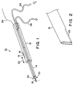
- Electrocautery instrument 10 comprises a handle 12, a suction tube 14, and an electrocautery electrode/blade 16.
- Handle 12 is preferably made of a sterilizable, rigid, and non-conductive material, such as nylon or the like.
- Suction tube 14, which is also preferably made of a sterilizable and non-conductive material, is slidably disposed partially within an internal lumen of handle 12, and projects distally out of the end thereof.
- Electrode/blade 16 is disposed within suction tube 14 and handle 12.
- Suction tube 14 is adapted to slide proximally and distally with respect to handle 12 and electrode 16 (i.e., in the directions of arrow 20 in Figure 1) by means of a sliding lever 18 extending out of a slot 19 in handle 12. With suction tube 14 in a retracted position, as shown in Figure 1, a distal portion of electrode/blade 16 projects beyond the distal end of tube 14, such that electrocautery can be performed. With suction tube in an advanced position, suction tube 14 completely conceals the tip of electrode/blade 16.
- electrode/blade 16 is preferably implemented using a hollow cylindrical tube which has been flattened at its distal end, as shown in the greatly enlarged perspective view of Figure 2. In addition to being flattened, a portion of the distal end of electrode/blade 16 is removed to form a longitudinal slit 22 therein.
- Electrocautery instrument 10 One terminal (e.g., positive) of a radio-frequency (RF) generator (not shown in Figure 1) is electrically coupled to electrode/blade 16 via a wire 24; a source of fluid to be expelled from slit 22 in electrode/blade 16 is coupled to the proximal end of electrode/blade 16 via a flexible tube or hose 26; and a suction hose 28 is coupled to handle 12 so as to be in communication with the internal lumen of handle 12 and with suction tube 14.
- RF radio-frequency
- conductive fluid is communicated from inflow tube 26 and communicated along the length of electrode/blade 16 to be expelled from the distal end thereof. This is done in order to establish a so-called virtual electrode for performing electrocautery.
- the infusion of conductive fluid simultaneously with the application of RF energy is discussed in further detail in: US patent number 5,431,649, in US patent number 5,609,151; and in US patent number 5,876,398.
- the foregoing patents are hereinafter collectively referred to as "the RF ablation applications”.
- the infusion of conducting fluid into the area of application of RF energy creates a "virtual electrode," the size and shape of which can be controllably modified, and which can be rendered more or less conductive, thereby modifying the spread of RF energy.
- the rate of infusion of conductive liquid, and the conductivity of the infused solution can be controlled.
- application of the conductive solution during the application of RF energy further assists by preventing overheating of the electrode/blade, extending the point at which burning or charring of tissue would otherwise normally occur.
- the solution being infused may first be cooled.
- Conductive solutions believed to be suitable for establishing the virtual electrode include saline, saturated saline, and Ringer's solution, among others.
- a conventional pump may be coupled to input line 26.
- a small, pre-pressurized canister of conductive solution may be used, such that no pump is required.
- handle 12 may be configured to receive such a pressurized canister therein, eliminating the need for input line 26.
- input line 26, suction line 28, and electrical connection 24 are depicted separately, it is contemplated that these connections to instrument 10 may be consolidated into a single line having two separate fluid-conducting lumens therein (one for input of conductive solution, one for suction), alongside an insulated electrical conductor.
- electrode/blade 16 Various alternative configurations of electrode/blade 16 are also contemplated.
- a porous metal element is substituted for the flattened tube configuration of Figures 1 and 2.
Landscapes
- Health & Medical Sciences (AREA)
- Surgery (AREA)
- Engineering & Computer Science (AREA)
- Life Sciences & Earth Sciences (AREA)
- Medical Informatics (AREA)
- General Health & Medical Sciences (AREA)
- Nuclear Medicine, Radiotherapy & Molecular Imaging (AREA)
- Plasma & Fusion (AREA)
- Biomedical Technology (AREA)
- Heart & Thoracic Surgery (AREA)
- Physics & Mathematics (AREA)
- Molecular Biology (AREA)
- Animal Behavior & Ethology (AREA)
- Otolaryngology (AREA)
- Public Health (AREA)
- Veterinary Medicine (AREA)
- Surgical Instruments (AREA)
- Physical Or Chemical Processes And Apparatus (AREA)
- Paper (AREA)
- Organic Low-Molecular-Weight Compounds And Preparation Thereof (AREA)
- Materials For Medical Uses (AREA)
Abstract
Description
Claims (4)
- A system for performing fluid-assisted electrocautery, said system comprising a fluid-assisted electrocautery instrument (10), comprising:an elongate handle (12) having proximal and distal ends and having a longitudinal lumen extending between said proximal and distal ends;a conductive electrocautery electrode (16) adapted to be coupled to a source of radio-frequency energy, said electrode comprising an elongate tube defining an internal lumen extending between proximal and distal ends of said electrode;a fluid input tube (26), coupled to said proximal end of said electrode and in fluid communication with said internal lumen of said electrode, such that conductive fluid supplied from said input tube is communicated along said electrode and expelled from said distal end of said electrode; a suction tube (14), disposed partially within said lumen of said handle and having a distal end extending out of said distal end of said handle; wherein suction is applied to said suction tube to draw air and fluid into the distal end of said suction tube (14); and wherein said electrode (16) is disposed within said suction tube (14) such that a distal end of said electrode extends distally beyond said distal end of suction tube; and said system further comprisinga suction pump coupled to said proximal end of said suction tube.
- An electrocautery instrument in accordance with claim 1, wherein said distal end of said electrode (16) is flattened into a blade-like configuration.
- An electrocautery instrument in accordance with claim 1 or 2, further comprising: a suction hose (28), adapted to be coupled between said proximal end of said suction tube and the suction pump, for aspirating smoke and fluid during electrocautery.
- An electrocautery instrument in accordance with claim 1, 2 or 3 wherein said suction tube (14) is slidably disposed in said handle (12) such that said suction tube is slidable between a fully retracted position wherein a distal end of said electrode (16) extends beyond said distal end of said suction tube, and a fully advanced position wherein said distal end of said electrode is disposed within said suction tube.
Priority Applications (1)
| Application Number | Priority Date | Filing Date | Title |
|---|---|---|---|
| EP05019834A EP1602338B1 (en) | 1996-10-02 | 1996-10-02 | Fluid-assisted electrocautery device |
Applications Claiming Priority (1)
| Application Number | Priority Date | Filing Date | Title |
|---|---|---|---|
| PCT/US1996/015796 WO1998014131A1 (en) | 1996-10-02 | 1996-10-02 | Fluid-assisted electrocautery device |
Related Child Applications (1)
| Application Number | Title | Priority Date | Filing Date |
|---|---|---|---|
| EP05019834A Division EP1602338B1 (en) | 1996-10-02 | 1996-10-02 | Fluid-assisted electrocautery device |
Publications (2)
| Publication Number | Publication Date |
|---|---|
| EP1007111A1 EP1007111A1 (en) | 2000-06-14 |
| EP1007111B1 true EP1007111B1 (en) | 2005-09-14 |
Family
ID=22255895
Family Applications (2)
| Application Number | Title | Priority Date | Filing Date |
|---|---|---|---|
| EP96936132A Expired - Lifetime EP1007111B1 (en) | 1996-10-02 | 1996-10-02 | Fluid-assisted electrocautery device |
| EP05019834A Expired - Lifetime EP1602338B1 (en) | 1996-10-02 | 1996-10-02 | Fluid-assisted electrocautery device |
Family Applications After (1)
| Application Number | Title | Priority Date | Filing Date |
|---|---|---|---|
| EP05019834A Expired - Lifetime EP1602338B1 (en) | 1996-10-02 | 1996-10-02 | Fluid-assisted electrocautery device |
Country Status (7)
| Country | Link |
|---|---|
| EP (2) | EP1007111B1 (en) |
| JP (1) | JP4545236B2 (en) |
| AT (1) | ATE304376T1 (en) |
| AU (1) | AU730289B2 (en) |
| CA (1) | CA2266073C (en) |
| DE (1) | DE69635195T2 (en) |
| WO (1) | WO1998014131A1 (en) |
Cited By (1)
| Publication number | Priority date | Publication date | Assignee | Title |
|---|---|---|---|---|
| US11039875B2 (en) | 2016-04-26 | 2021-06-22 | Kirwan Surgical Products Llc | Non-stick monopolar suction coagulator |
Families Citing this family (28)
| Publication number | Priority date | Publication date | Assignee | Title |
|---|---|---|---|---|
| US7811282B2 (en) | 2000-03-06 | 2010-10-12 | Salient Surgical Technologies, Inc. | Fluid-assisted electrosurgical devices, electrosurgical unit with pump and methods of use thereof |
| US8048070B2 (en) | 2000-03-06 | 2011-11-01 | Salient Surgical Technologies, Inc. | Fluid-assisted medical devices, systems and methods |
| US6558385B1 (en) * | 2000-09-22 | 2003-05-06 | Tissuelink Medical, Inc. | Fluid-assisted medical device |
| US9554843B2 (en) | 2006-09-01 | 2017-01-31 | Conmed Corporation | Adapter and method for converting gas-enhanced electrosurgical coagulation instrument for cutting |
| US20080132888A1 (en) * | 2006-12-04 | 2008-06-05 | Olympus Medical Systems Corp. | Electrosurgical instrument |
| US8057470B2 (en) * | 2007-08-30 | 2011-11-15 | Conmed Corporation | Integrated smoke evacuation electrosurgical pencil and method |
| US10064697B2 (en) | 2008-10-06 | 2018-09-04 | Santa Anna Tech Llc | Vapor based ablation system for treating various indications |
| US9561068B2 (en) | 2008-10-06 | 2017-02-07 | Virender K. Sharma | Method and apparatus for tissue ablation |
| US9561066B2 (en) | 2008-10-06 | 2017-02-07 | Virender K. Sharma | Method and apparatus for tissue ablation |
| US20100094270A1 (en) | 2008-10-06 | 2010-04-15 | Sharma Virender K | Method and Apparatus for Tissue Ablation |
| US10695126B2 (en) | 2008-10-06 | 2020-06-30 | Santa Anna Tech Llc | Catheter with a double balloon structure to generate and apply a heated ablative zone to tissue |
| US8355799B2 (en) | 2008-12-12 | 2013-01-15 | Arthrocare Corporation | Systems and methods for limiting joint temperature |
| US8137345B2 (en) * | 2009-01-05 | 2012-03-20 | Peak Surgical, Inc. | Electrosurgical devices for tonsillectomy and adenoidectomy |
| BRPI0904765A2 (en) | 2009-11-10 | 2011-07-12 | Univ Minas Gerais | ionic solution-specific hepatotomy electrocautery device |
| US8979838B2 (en) | 2010-05-24 | 2015-03-17 | Arthrocare Corporation | Symmetric switching electrode method and related system |
| US9011421B2 (en) * | 2011-01-05 | 2015-04-21 | Covidien Lp | Energy-delivery devices with flexible fluid-cooled shaft, inflow/outflow junctions suitable for use with same, and systems including same |
| WO2012170364A1 (en) | 2011-06-10 | 2012-12-13 | Medtronic, Inc. | Wire electrode devices for tonsillectomy and adenoidectomy |
| EP2801333A4 (en) | 2012-04-20 | 2015-10-14 | Olympus Medical Systems Corp | Surgical device |
| JP2014008101A (en) * | 2012-06-28 | 2014-01-20 | Tadashi Kawakita | Thermotherapeutic device |
| WO2014113724A2 (en) | 2013-01-17 | 2014-07-24 | Sharma Virender K | Method and apparatus for tissue ablation |
| US9526556B2 (en) | 2014-02-28 | 2016-12-27 | Arthrocare Corporation | Systems and methods systems related to electrosurgical wands with screen electrodes |
| US9597142B2 (en) | 2014-07-24 | 2017-03-21 | Arthrocare Corporation | Method and system related to electrosurgical procedures |
| US9649148B2 (en) | 2014-07-24 | 2017-05-16 | Arthrocare Corporation | Electrosurgical system and method having enhanced arc prevention |
| US11331140B2 (en) | 2016-05-19 | 2022-05-17 | Aqua Heart, Inc. | Heated vapor ablation systems and methods for treating cardiac conditions |
| CN110402117B (en) * | 2017-03-22 | 2022-08-05 | 磁疗血栓切除术解决方案有限公司 | Thrombectomy with electrostatic and suction forces |
| EP3713507B1 (en) | 2017-11-23 | 2023-08-02 | Magneto Thrombectomy Solutions Ltd. | Tubular thrombectomy devices |
| WO2019191071A1 (en) * | 2018-03-27 | 2019-10-03 | Boston Scientific Scimed, Inc. | Medical devices and related methods |
| CN113015494A (en) | 2018-06-01 | 2021-06-22 | 圣安娜技术有限公司 | Multi-stage steam ablation therapy method and steam generation and delivery system |
Family Cites Families (17)
| Publication number | Priority date | Publication date | Assignee | Title |
|---|---|---|---|---|
| US1735271A (en) * | 1928-03-14 | 1929-11-12 | Sutten H Groff | Diathermy knife |
| US4060088A (en) * | 1976-01-16 | 1977-11-29 | Valleylab, Inc. | Electrosurgical method and apparatus for establishing an electrical discharge in an inert gas flow |
| US4326529A (en) * | 1978-05-26 | 1982-04-27 | The United States Of America As Represented By The United States Department Of Energy | Corneal-shaping electrode |
| US4307720A (en) | 1979-07-26 | 1981-12-29 | Weber Jr Jaroy | Electrocautery apparatus and method and means for cleaning the same |
| GB8822492D0 (en) * | 1988-09-24 | 1988-10-26 | Considine J | Apparatus for removing tumours from hollow organs of body |
| JPH0734805B2 (en) * | 1990-05-16 | 1995-04-19 | アロカ株式会社 | Blood coagulator |
| US5195959A (en) * | 1991-05-31 | 1993-03-23 | Paul C. Smith | Electrosurgical device with suction and irrigation |
| US5242442A (en) | 1991-09-18 | 1993-09-07 | Hirschfeld Jack J | Smoke aspirating electrosurgical device |
| US5269781A (en) | 1992-06-10 | 1993-12-14 | Hewell Iii Todd S | Suction-assisted electrocautery unit |
| US5401272A (en) * | 1992-09-25 | 1995-03-28 | Envision Surgical Systems, Inc. | Multimodality probe with extendable bipolar electrodes |
| JP2931102B2 (en) * | 1993-05-10 | 1999-08-09 | アースロケア コーポレイション | Electrosurgical probe |
| US5431649A (en) | 1993-08-27 | 1995-07-11 | Medtronic, Inc. | Method and apparatus for R-F ablation |
| US5472441A (en) * | 1993-11-08 | 1995-12-05 | Zomed International | Device for treating cancer and non-malignant tumors and methods |
| US5462521A (en) * | 1993-12-21 | 1995-10-31 | Angeion Corporation | Fluid cooled and perfused tip for a catheter |
| US5876398A (en) | 1994-09-08 | 1999-03-02 | Medtronic, Inc. | Method and apparatus for R-F ablation |
| US5609151A (en) * | 1994-09-08 | 1997-03-11 | Medtronic, Inc. | Method for R-F ablation |
| US5897553A (en) * | 1995-11-02 | 1999-04-27 | Medtronic, Inc. | Ball point fluid-assisted electrocautery device |
-
1996
- 1996-10-02 AT AT96936132T patent/ATE304376T1/en not_active IP Right Cessation
- 1996-10-02 AU AU73857/96A patent/AU730289B2/en not_active Expired
- 1996-10-02 JP JP51646298A patent/JP4545236B2/en not_active Expired - Lifetime
- 1996-10-02 DE DE69635195T patent/DE69635195T2/en not_active Expired - Lifetime
- 1996-10-02 EP EP96936132A patent/EP1007111B1/en not_active Expired - Lifetime
- 1996-10-02 WO PCT/US1996/015796 patent/WO1998014131A1/en active IP Right Grant
- 1996-10-02 EP EP05019834A patent/EP1602338B1/en not_active Expired - Lifetime
- 1996-10-02 CA CA002266073A patent/CA2266073C/en not_active Expired - Lifetime
Cited By (1)
| Publication number | Priority date | Publication date | Assignee | Title |
|---|---|---|---|---|
| US11039875B2 (en) | 2016-04-26 | 2021-06-22 | Kirwan Surgical Products Llc | Non-stick monopolar suction coagulator |
Also Published As
| Publication number | Publication date |
|---|---|
| JP4545236B2 (en) | 2010-09-15 |
| EP1602338B1 (en) | 2011-12-07 |
| EP1007111A1 (en) | 2000-06-14 |
| CA2266073C (en) | 2006-08-08 |
| JP2001501513A (en) | 2001-02-06 |
| EP1602338A3 (en) | 2006-05-17 |
| AU730289B2 (en) | 2001-03-01 |
| EP1602338A2 (en) | 2005-12-07 |
| ATE304376T1 (en) | 2005-09-15 |
| DE69635195D1 (en) | 2005-10-20 |
| WO1998014131A1 (en) | 1998-04-09 |
| CA2266073A1 (en) | 1998-04-09 |
| DE69635195T2 (en) | 2006-06-29 |
| AU7385796A (en) | 1998-04-24 |
Similar Documents
| Publication | Publication Date | Title |
|---|---|---|
| US6475216B2 (en) | Fluid-assisted electrocautery method | |
| EP1007111B1 (en) | Fluid-assisted electrocautery device | |
| AU697542B2 (en) | Ball point fluid-assisted electrocautery device | |
| US6482202B1 (en) | Under water treatment | |
| US6074389A (en) | Electrosurgery with cooled electrodes | |
| US6852111B1 (en) | Laparoscopic electrotome | |
| JP2007527766A (en) | Multifunctional telescopic universal unipolar / bipolar surgical device and method therefor | |
| AU759356B2 (en) | Fluid-assisted electrocautery device |
Legal Events
| Date | Code | Title | Description |
|---|---|---|---|
| PUAI | Public reference made under article 153(3) epc to a published international application that has entered the european phase |
Free format text: ORIGINAL CODE: 0009012 |
|
| 17P | Request for examination filed |
Effective date: 19990409 |
|
| AK | Designated contracting states |
Kind code of ref document: A1 Designated state(s): AT BE CH DE DK ES FI FR GB GR IE IT LI LU MC NL PT SE |
|
| 17Q | First examination report despatched |
Effective date: 20030605 |
|
| RAP1 | Party data changed (applicant data changed or rights of an application transferred) |
Owner name: MEDTRONIC, INC. |
|
| GRAP | Despatch of communication of intention to grant a patent |
Free format text: ORIGINAL CODE: EPIDOSNIGR1 |
|
| GRAS | Grant fee paid |
Free format text: ORIGINAL CODE: EPIDOSNIGR3 |
|
| GRAA | (expected) grant |
Free format text: ORIGINAL CODE: 0009210 |
|
| AK | Designated contracting states |
Kind code of ref document: B1 Designated state(s): AT BE CH DE DK ES FI FR GB GR IE IT LI LU MC NL PT SE |
|
| PG25 | Lapsed in a contracting state [announced via postgrant information from national office to epo] |
Ref country code: NL Free format text: LAPSE BECAUSE OF FAILURE TO SUBMIT A TRANSLATION OF THE DESCRIPTION OR TO PAY THE FEE WITHIN THE PRESCRIBED TIME-LIMIT Effective date: 20050914 Ref country code: LI Free format text: LAPSE BECAUSE OF FAILURE TO SUBMIT A TRANSLATION OF THE DESCRIPTION OR TO PAY THE FEE WITHIN THE PRESCRIBED TIME-LIMIT Effective date: 20050914 Ref country code: IT Free format text: LAPSE BECAUSE OF FAILURE TO SUBMIT A TRANSLATION OF THE DESCRIPTION OR TO PAY THE FEE WITHIN THE PRE;WARNING: LAPSES OF ITALIAN PATENTS WITH EFFECTIVE DATE BEFORE 2007 MAY HAVE OCCURRED AT ANY TIME BEFORE 2007. THE CORRECT EFFECTIVE DATE MAY BE DIFFERENT FROM THE ONE RECORDED.SCRIBED TIME-LIMIT Effective date: 20050914 Ref country code: FI Free format text: LAPSE BECAUSE OF FAILURE TO SUBMIT A TRANSLATION OF THE DESCRIPTION OR TO PAY THE FEE WITHIN THE PRESCRIBED TIME-LIMIT Effective date: 20050914 Ref country code: CH Free format text: LAPSE BECAUSE OF FAILURE TO SUBMIT A TRANSLATION OF THE DESCRIPTION OR TO PAY THE FEE WITHIN THE PRESCRIBED TIME-LIMIT Effective date: 20050914 Ref country code: BE Free format text: LAPSE BECAUSE OF FAILURE TO SUBMIT A TRANSLATION OF THE DESCRIPTION OR TO PAY THE FEE WITHIN THE PRESCRIBED TIME-LIMIT Effective date: 20050914 Ref country code: AT Free format text: LAPSE BECAUSE OF FAILURE TO SUBMIT A TRANSLATION OF THE DESCRIPTION OR TO PAY THE FEE WITHIN THE PRESCRIBED TIME-LIMIT Effective date: 20050914 |
|
| REG | Reference to a national code |
Ref country code: GB Ref legal event code: FG4D |
|
| REG | Reference to a national code |
Ref country code: CH Ref legal event code: EP |
|
| PG25 | Lapsed in a contracting state [announced via postgrant information from national office to epo] |
Ref country code: IE Free format text: LAPSE BECAUSE OF NON-PAYMENT OF DUE FEES Effective date: 20051003 |
|
| REG | Reference to a national code |
Ref country code: IE Ref legal event code: FG4D |
|
| REF | Corresponds to: |
Ref document number: 69635195 Country of ref document: DE Date of ref document: 20051020 Kind code of ref document: P |
|
| PG25 | Lapsed in a contracting state [announced via postgrant information from national office to epo] |
Ref country code: MC Free format text: LAPSE BECAUSE OF NON-PAYMENT OF DUE FEES Effective date: 20051031 |
|
| PG25 | Lapsed in a contracting state [announced via postgrant information from national office to epo] |
Ref country code: LU Free format text: LAPSE BECAUSE OF NON-PAYMENT OF DUE FEES Effective date: 20051114 |
|
| PG25 | Lapsed in a contracting state [announced via postgrant information from national office to epo] |
Ref country code: SE Free format text: LAPSE BECAUSE OF FAILURE TO SUBMIT A TRANSLATION OF THE DESCRIPTION OR TO PAY THE FEE WITHIN THE PRESCRIBED TIME-LIMIT Effective date: 20051214 Ref country code: GR Free format text: LAPSE BECAUSE OF FAILURE TO SUBMIT A TRANSLATION OF THE DESCRIPTION OR TO PAY THE FEE WITHIN THE PRESCRIBED TIME-LIMIT Effective date: 20051214 Ref country code: GB Free format text: LAPSE BECAUSE OF NON-PAYMENT OF DUE FEES Effective date: 20051214 Ref country code: DK Free format text: LAPSE BECAUSE OF FAILURE TO SUBMIT A TRANSLATION OF THE DESCRIPTION OR TO PAY THE FEE WITHIN THE PRESCRIBED TIME-LIMIT Effective date: 20051214 |
|
| PG25 | Lapsed in a contracting state [announced via postgrant information from national office to epo] |
Ref country code: ES Free format text: LAPSE BECAUSE OF FAILURE TO SUBMIT A TRANSLATION OF THE DESCRIPTION OR TO PAY THE FEE WITHIN THE PRESCRIBED TIME-LIMIT Effective date: 20051225 |
|
| PG25 | Lapsed in a contracting state [announced via postgrant information from national office to epo] |
Ref country code: PT Free format text: LAPSE BECAUSE OF FAILURE TO SUBMIT A TRANSLATION OF THE DESCRIPTION OR TO PAY THE FEE WITHIN THE PRESCRIBED TIME-LIMIT Effective date: 20060214 |
|
| NLV1 | Nl: lapsed or annulled due to failure to fulfill the requirements of art. 29p and 29m of the patents act | ||
| REG | Reference to a national code |
Ref country code: CH Ref legal event code: PL |
|
| ET | Fr: translation filed | ||
| PLBE | No opposition filed within time limit |
Free format text: ORIGINAL CODE: 0009261 |
|
| STAA | Information on the status of an ep patent application or granted ep patent |
Free format text: STATUS: NO OPPOSITION FILED WITHIN TIME LIMIT |
|
| REG | Reference to a national code |
Ref country code: IE Ref legal event code: MM4A |
|
| 26N | No opposition filed |
Effective date: 20060615 |
|
| GBPC | Gb: european patent ceased through non-payment of renewal fee |
Effective date: 20051214 |
|
| REG | Reference to a national code |
Ref country code: FR Ref legal event code: PLFP Year of fee payment: 20 |
|
| PGFP | Annual fee paid to national office [announced via postgrant information from national office to epo] |
Ref country code: DE Payment date: 20151028 Year of fee payment: 20 |
|
| PGFP | Annual fee paid to national office [announced via postgrant information from national office to epo] |
Ref country code: FR Payment date: 20151019 Year of fee payment: 20 |
|
| REG | Reference to a national code |
Ref country code: DE Ref legal event code: R071 Ref document number: 69635195 Country of ref document: DE |