EP1002686A2 - Vehicle with auxiliary traveling device - Google Patents
Vehicle with auxiliary traveling device Download PDFInfo
- Publication number
- EP1002686A2 EP1002686A2 EP99119243A EP99119243A EP1002686A2 EP 1002686 A2 EP1002686 A2 EP 1002686A2 EP 99119243 A EP99119243 A EP 99119243A EP 99119243 A EP99119243 A EP 99119243A EP 1002686 A2 EP1002686 A2 EP 1002686A2
- Authority
- EP
- European Patent Office
- Prior art keywords
- traveling
- power transmission
- speed
- shaft
- normal
- Prior art date
- Legal status (The legal status is an assumption and is not a legal conclusion. Google has not performed a legal analysis and makes no representation as to the accuracy of the status listed.)
- Withdrawn
Links
- 230000005540 biological transmission Effects 0.000 claims abstract description 135
- 230000007935 neutral effect Effects 0.000 claims abstract description 44
- 239000003638 chemical reducing agent Substances 0.000 claims abstract description 10
- XLYOFNOQVPJJNP-UHFFFAOYSA-N water Substances O XLYOFNOQVPJJNP-UHFFFAOYSA-N 0.000 claims description 6
- 238000004140 cleaning Methods 0.000 description 11
- 238000010276 construction Methods 0.000 description 4
- 238000009434 installation Methods 0.000 description 3
- 238000007792 addition Methods 0.000 description 1
- 238000002485 combustion reaction Methods 0.000 description 1
- 239000000428 dust Substances 0.000 description 1
- 238000004519 manufacturing process Methods 0.000 description 1
- 239000010893 paper waste Substances 0.000 description 1
- 230000000630 rising effect Effects 0.000 description 1
- 239000004576 sand Substances 0.000 description 1
- 239000000126 substance Substances 0.000 description 1
Images


Classifications
-
- B—PERFORMING OPERATIONS; TRANSPORTING
- B60—VEHICLES IN GENERAL
- B60K—ARRANGEMENT OR MOUNTING OF PROPULSION UNITS OR OF TRANSMISSIONS IN VEHICLES; ARRANGEMENT OR MOUNTING OF PLURAL DIVERSE PRIME-MOVERS IN VEHICLES; AUXILIARY DRIVES FOR VEHICLES; INSTRUMENTATION OR DASHBOARDS FOR VEHICLES; ARRANGEMENTS IN CONNECTION WITH COOLING, AIR INTAKE, GAS EXHAUST OR FUEL SUPPLY OF PROPULSION UNITS IN VEHICLES
- B60K17/00—Arrangement or mounting of transmissions in vehicles
- B60K17/28—Arrangement or mounting of transmissions in vehicles characterised by arrangement, location, or type of power take-off
-
- B—PERFORMING OPERATIONS; TRANSPORTING
- B60—VEHICLES IN GENERAL
- B60K—ARRANGEMENT OR MOUNTING OF PROPULSION UNITS OR OF TRANSMISSIONS IN VEHICLES; ARRANGEMENT OR MOUNTING OF PLURAL DIVERSE PRIME-MOVERS IN VEHICLES; AUXILIARY DRIVES FOR VEHICLES; INSTRUMENTATION OR DASHBOARDS FOR VEHICLES; ARRANGEMENTS IN CONNECTION WITH COOLING, AIR INTAKE, GAS EXHAUST OR FUEL SUPPLY OF PROPULSION UNITS IN VEHICLES
- B60K17/00—Arrangement or mounting of transmissions in vehicles
-
- B—PERFORMING OPERATIONS; TRANSPORTING
- B60—VEHICLES IN GENERAL
- B60K—ARRANGEMENT OR MOUNTING OF PROPULSION UNITS OR OF TRANSMISSIONS IN VEHICLES; ARRANGEMENT OR MOUNTING OF PLURAL DIVERSE PRIME-MOVERS IN VEHICLES; AUXILIARY DRIVES FOR VEHICLES; INSTRUMENTATION OR DASHBOARDS FOR VEHICLES; ARRANGEMENTS IN CONNECTION WITH COOLING, AIR INTAKE, GAS EXHAUST OR FUEL SUPPLY OF PROPULSION UNITS IN VEHICLES
- B60K6/00—Arrangement or mounting of plural diverse prime-movers for mutual or common propulsion, e.g. hybrid propulsion systems comprising electric motors and internal combustion engines ; Control systems therefor, i.e. systems controlling two or more prime movers, or controlling one of these prime movers and any of the transmission, drive or drive units Informative references: mechanical gearings with secondary electric drive F16H3/72; arrangements for handling mechanical energy structurally associated with the dynamo-electric machine H02K7/00; machines comprising structurally interrelated motor and generator parts H02K51/00; dynamo-electric machines not otherwise provided for in H02K see H02K99/00
- B60K6/08—Prime-movers comprising combustion engines and mechanical or fluid energy storing means
- B60K6/12—Prime-movers comprising combustion engines and mechanical or fluid energy storing means by means of a chargeable fluidic accumulator
-
- B—PERFORMING OPERATIONS; TRANSPORTING
- B60—VEHICLES IN GENERAL
- B60W—CONJOINT CONTROL OF VEHICLE SUB-UNITS OF DIFFERENT TYPE OR DIFFERENT FUNCTION; CONTROL SYSTEMS SPECIALLY ADAPTED FOR HYBRID VEHICLES; ROAD VEHICLE DRIVE CONTROL SYSTEMS FOR PURPOSES NOT RELATED TO THE CONTROL OF A PARTICULAR SUB-UNIT
- B60W30/00—Purposes of road vehicle drive control systems not related to the control of a particular sub-unit, e.g. of systems using conjoint control of vehicle sub-units
- B60W30/18—Propelling the vehicle
- B60W30/18009—Propelling the vehicle related to particular drive situations
- B60W30/18063—Creeping
-
- B—PERFORMING OPERATIONS; TRANSPORTING
- B60—VEHICLES IN GENERAL
- B60K—ARRANGEMENT OR MOUNTING OF PROPULSION UNITS OR OF TRANSMISSIONS IN VEHICLES; ARRANGEMENT OR MOUNTING OF PLURAL DIVERSE PRIME-MOVERS IN VEHICLES; AUXILIARY DRIVES FOR VEHICLES; INSTRUMENTATION OR DASHBOARDS FOR VEHICLES; ARRANGEMENTS IN CONNECTION WITH COOLING, AIR INTAKE, GAS EXHAUST OR FUEL SUPPLY OF PROPULSION UNITS IN VEHICLES
- B60K17/00—Arrangement or mounting of transmissions in vehicles
- B60K17/04—Arrangement or mounting of transmissions in vehicles characterised by arrangement, location, or kind of gearing
- B60K17/10—Arrangement or mounting of transmissions in vehicles characterised by arrangement, location, or kind of gearing of fluid gearing
-
- Y—GENERAL TAGGING OF NEW TECHNOLOGICAL DEVELOPMENTS; GENERAL TAGGING OF CROSS-SECTIONAL TECHNOLOGIES SPANNING OVER SEVERAL SECTIONS OF THE IPC; TECHNICAL SUBJECTS COVERED BY FORMER USPC CROSS-REFERENCE ART COLLECTIONS [XRACs] AND DIGESTS
- Y02—TECHNOLOGIES OR APPLICATIONS FOR MITIGATION OR ADAPTATION AGAINST CLIMATE CHANGE
- Y02T—CLIMATE CHANGE MITIGATION TECHNOLOGIES RELATED TO TRANSPORTATION
- Y02T10/00—Road transport of goods or passengers
- Y02T10/60—Other road transportation technologies with climate change mitigation effect
- Y02T10/62—Hybrid vehicles
-
- Y—GENERAL TAGGING OF NEW TECHNOLOGICAL DEVELOPMENTS; GENERAL TAGGING OF CROSS-SECTIONAL TECHNOLOGIES SPANNING OVER SEVERAL SECTIONS OF THE IPC; TECHNICAL SUBJECTS COVERED BY FORMER USPC CROSS-REFERENCE ART COLLECTIONS [XRACs] AND DIGESTS
- Y10—TECHNICAL SUBJECTS COVERED BY FORMER USPC
- Y10T—TECHNICAL SUBJECTS COVERED BY FORMER US CLASSIFICATION
- Y10T74/00—Machine element or mechanism
- Y10T74/19—Gearing
- Y10T74/19149—Gearing with fluid drive
- Y10T74/19158—Gearing with fluid drive with one or more controllers for gearing, fluid drive, or clutch
- Y10T74/19163—Gearing with fluid drive with one or more controllers for gearing, fluid drive, or clutch with interrelated controls
Definitions
- the present invention relates to a vehicle with an auxiliary traveling device.
- Normal vehicle may run at a high speed higher than or equal to 100 km/h. However, it is typical that the vehicle is not provided a primary power transmission having a power transmission ratio permitting to run at inching speed in the extent lower than 5 km/h when a prime mover for traveling is a high revolution speed and high output.
- a power transmission which has different power transmission ratio other than that of a power transmission of the normal vehicle have to be installed.
- the vehicle having such power transmission other than the power transmission of the normal vehicle normally does not have performance for high speed traveling unless a special vehicle which has a power transmission with sixteen stages of speed ratio, or so forth. Therefore, such vehicle has to be transported to a destination by a transporter or the like.
- the normal vehicle installed with an external power takeoff cannot simultaneously drive the external power takeoff during normal traveling by the primary prime mover or simultaneously drive the vehicle for normal traveling by the primary prime mover while the external power takeoff is in operation, forcedly.
- Various working vehicles such as so-called vacuum type suction cleaner vehicle, may travel to a destination, namely a working site, at high speed similarly to the normal vehicle.
- a destination namely a working site
- such working vehicle is not able to run at inching speed required for cleaning operation while predetermined suction cleaning operation is performed using the external power takeoff at the working site.
- the present invention has been worked out in view of drawbacks in the prior art as set forth above. Therefore, it is an object of the present invention to provide a vehicle which can achieve high speed traveling performance as achieved by a normal vehicle, and can be continuously driven at inching speed in the extent of lower than 5 km/h with a traveling prime mover of high revolution speed and high output at a destination.
- a vehicle with an auxiliary traveling device comprises:
- a vehicle with an auxiliary traveling device which travels at a normal traveling speed by transmitting a rotational torque of a traveling prime mover to driving wheels via a rotary power transmission shaft, a drive shaft speed reducer and a drive shaft while a normal traveling primary power transmission is in a range other than a neutral range, and performs a required work by transmitting the rotational torque of the traveling prime mover to an external work implement via an external power takeoff mechanism when the normal traveling primary power transmission is in the neutral range, comprises:
- the vehicle with an auxiliary traveling device comprises:
- the hydraulically controlled power transmission for traveling at inching speed is constructed by extending a rotational power transmission shaft through a hydraulic vessel, on which the hydraulic motor is externally installed, connecting a first rotary power transmission shaft and a second rotary power transmission shaft with the rotary power transmission shaft at both ends, and assembling a connecting and disconnecting device for traveling at inching speed constituted of a first drive disc supported on the rotary power transmission shaft for free rotation with respect to the rotary power transmission shaft and a second drive disc fixed on the rotary power transmission shaft and operated for establishing and releasing connection by electrical signal or pneumatic pressure from a vehicular cabin.
- control for connecting and disconnecting of the first and second drive discs in the connecting and disconnecting device for traveling at inching speed is performed by an electrical signal from the vehicular cabin, and in response to shifting of the primary power transmission for normal traveling to the position other than the neutral range position during operation of the external power takeoff, the external power takeoff and the connecting and disconnecting device for traveling at inching speed inoperative position in response to an electrical signal from the neutral position detector incorporated in the primary power transmission for normal traveling, instantly.
- a vehicle with an auxiliary traveling device will be discussed hereinafter in detail in terms of a vacuum type suction cleaning vehicle which is installed an external power takeoff and is designed for continuously collecting particulate substance such as sand or the like, and leaf-like matter such as fallen leaves, paper waste or so forth residing on a road surface.
- Fig. 1 generally shows a construction of a power transmission mechanism A of the construction discussed below.
- the reference numeral 1 denotes a traveling prime mover, i.e. an internal combustion engine
- 2 denotes a connecting and disconnecting device, i.e. a clutch
- 3 denotes a primary power transmission for normal traveling provided with an external power takeoff (PTO) 3'
- 4 denotes a rotary power transmission
- 5 denotes a rotary power transmission B shaft (propeller shaft)
- 6 denotes a drive shaft speed reducer (differential gear box)
- 7 denotes a drive shaft
- 8 denotes driving wheels
- 9 denotes a steering wheel (handle) provided within a vehicular cabin 26
- 10 denotes a wheel shaft and 11 denotes driven wheels.
- the reference numeral 12 denotes an external power takeoff shaft of the external power takeoff mechanism 3'
- 15 denotes a vacuum generating device forming a vacuum suction mechanism which will be discussed later.
- the external power takeoff shaft 12 and the vacuum generating device 15 are mechanically linked by V-pulleys 13 and 14 and a V-belt 23.
- the reference numeral 19 denotes a high water pressure generating device.
- the high water pressure generating device 19 and the external power takeoff shaft 12 are mechanically linked by V-pulleys 16 and 17, a V-belt 24 and a connecting and disconnecting device (clutch) 18 for the high water pressure generating device.
- the reference numeral 20 denotes a hydraulic pump serving as a hydraulic pressure generator, connected to the external power takeoff shaft 12, 21 denotes a hydraulic motor driven by introducing a hydraulic pressure generated by the hydraulic pump 20, 22 denotes a hydraulically controlled power transmission for traveling at inching speed mechanically linking the rotary power transmission A shaft 4 and the rotary power transmission B shaft 5, and including the hydraulic motor 21.
- the hydraulic pump 20, the hydraulic motor 21 and the hydraulically controlled power transmission 22 for traveling at inching speed form an auxiliary traveling device B.
- the hydraulically controlled power transmission 22 for traveling at inching speed in the auxiliary traveling device B is constructed by extending a rotary power transmission shaft 34 through a hydraulic vessel 40, on which the hydraulic motor 21 is externally installed, connecting the rotary power transmission A shaft 4 and the rotary power transmission B shaft 5 with the rotary power transmission shaft 34 at both ends via universal joints 4' and 5', and assembling a connecting and disconnecting device (clutch) 35 for traveling at inching speed constituted of a drive disc 42 supported on the rotary power transmission shaft 34 for free rotation with respect to the rotary power transmission shaft 34 and a drive disc 43 fixed on the rotary power transmission shaft 34 and operated for establishing and releasing connection by electrical operation or by pneumatic pressure in response to an electrical signal from a vehicular cabin 26.
- a connecting and disconnecting device (clutch) 35 for traveling at inching speed constituted of a drive disc 42 supported on the rotary power transmission shaft 34 for free rotation with respect to the rotary power transmission shaft 34 and a drive disc 43 fixed on the rotary power transmission shaft 34 and
- the drive disc 42 is linked with the hydraulic motor 21 via a rotary power transmission driven gear 33 arranged integrally with the drive disc 42 and a rotary power transmission primary gear 32 fixed on an output shaft 21' of the hydraulic motor 21.
- the hydraulically controlled power transmission 22 for traveling at inching speed is mounted at a predetermined position on a chassis by a mounting beams 37, mounting members 38 and mounting brackets 39.
- the vacuum suction mechanism is constructed with the vacuum generating device 15 driven by revolution of the traveling prime mover 1 via the connecting and disconnecting device 2, the external power takeoff mechanism 3' provided on the primary power transmission 3 for normal traveling, the external power takeoff shaft 12, V-pulleys 13 and 14 and the V-belt 23, a collection vessel 65 connected to a vacuum piping 62 and a suction piping 62' of cylindrical shape for withstanding against a vacuum force, a dust catcher 63, a vacuum relief valve 64, a cleaning mouth 25 utilizing a high pressure water and compressed air, and so on. Furthermore, the collection vessel 65 can be lifted the front portion thereof about a fulcrum at the rear end by means of a hydraulic cylinder 66. A rear end of the collection vessel 65 is opened and closed by a door which is operated by a hydraulic cylinder 67.
- the reference numeral 69 in Fig. 5 is a water level detector.
- the vacuum type suction cleaning vehicle constructed as set forth above maintains the external power takeoff mechanism 3' and the connecting and disconnecting device 35 for traveling at inching speed inoperative during high speed normal traveling to the destination.
- the driving wheels 8 of the vacuum type suction cleaning vehicle is rotatingly driven by the traveling prime mover 1, the connecting and disconnecting device 2, the primary power transmission 3 for normal traveling, the rotary power transmission A shaft 4, the rotary power transmission B shaft 5, the drive shaft speed reducer 6, and the drive shaft 7 for driving the vehicle in forward and reverse directions.
- Orientation of the driven (front) wheels 11 are controlled by the steering wheel 9 in the vehicular cabin 26 for controlling traveling direction of the vehicle.
- the connecting and disconnecting device 35 for traveling at inching speed assembled in the hydraulically controlled power transmission 22 for traveling at inching speed is maintained inoperative as set forth above.
- the rotary power transmission driven gear 33 of the drive disc 42 will never be driven to rotate by the rotary power transmission primary gear 32.
- the connecting and disconnecting device 35 for traveling at inching speed is made operative.
- the primary power transmission 3 for normal traveling is placed at neutral range position by placing the connecting and disconnecting device in disconnecting state.
- the hydraulic pump 20 is driven by the traveling prime mover 1 via the external power takeoff mechanism 3' and the external power takeoff shaft 12. Then, by introducing the hydraulic pressure generated by the hydraulic pump 20, the hydraulic motor 21 is driven to rotatingly drive the rotary power transmission shaft 34.
- the rotary power transmission A shaft 4 as well as the rotary power transmission B shaft 5 are rotated to rotatingly drive the drive shaft speed reducer 6, the drive shaft 7 and the wheels 8 for travling in forward and reverse directions at the inching speed.
- orientation of the driven (front) wheels 11 are controlled by the steering wheel 9 in the vehicular cabin 26 for controlling traveling direction of the vehicle.
- control for connecting and disconnecting of the drive discs 42 and 43 in the connecting and disconnecting device 35 for traveling at inching speed is performed by the electrical signal from the vehicular cabin 26. If the primary power transmission 3 for normal traveling is unwantedly shifted to the position other than the neutral range position during operation of the external power takeoff mechanism 3', such shifting out of the neutral range position is detected by a not shown neutral position detector to generate an electrical signal to place the external power takeoff mechanism 3' and the connecting and disconnecting device 35 for traveling at inching speed inoperative position, instantly.
- the vehicle with the auxiliary traveling device according to the present invention can be driven either at the normal speed or the inching speed, selectively.
- the vehicle can be driven to travel at inching speed while the external work implement is in operation.
- the vehicle with the auxiliary traveling device according to the present invention can easily perform necessary operation without sacrificing high speed traveling performance which the vehicle can achieve normally, and with maintaining high revolution speed and high output of the traveling prime mover at working site.
Landscapes
- Engineering & Computer Science (AREA)
- Transportation (AREA)
- Mechanical Engineering (AREA)
- Chemical & Material Sciences (AREA)
- Combustion & Propulsion (AREA)
- Automation & Control Theory (AREA)
- Auxiliary Drives, Propulsion Controls, And Safety Devices (AREA)
- Arrangement And Driving Of Transmission Devices (AREA)
- Arrangement Of Transmissions (AREA)
- Motor Power Transmission Devices (AREA)
Abstract
Description
- The present invention relates to a vehicle with an auxiliary traveling device.
- Normal vehicle may run at a high speed higher than or equal to 100 km/h. However, it is typical that the vehicle is not provided a primary power transmission having a power transmission ratio permitting to run at inching speed in the extent lower than 5 km/h when a prime mover for traveling is a high revolution speed and high output.
- Accordingly, in case of a vehicle specialized for parade or a working vehicle which is required inching with a traveling prime mover of high revolution speed and high output, a power transmission which has different power transmission ratio other than that of a power transmission of the normal vehicle have to be installed. On the other hand, the vehicle having such power transmission other than the power transmission of the normal vehicle, normally does not have performance for high speed traveling unless a special vehicle which has a power transmission with sixteen stages of speed ratio, or so forth. Therefore, such vehicle has to be transported to a destination by a transporter or the like.
- On the other hand, the normal vehicle installed with an external power takeoff cannot simultaneously drive the external power takeoff during normal traveling by the primary prime mover or simultaneously drive the vehicle for normal traveling by the primary prime mover while the external power takeoff is in operation, forcedly.
- Various working vehicles, such as so-called vacuum type suction cleaner vehicle, may travel to a destination, namely a working site, at high speed similarly to the normal vehicle. However, such working vehicle is not able to run at inching speed required for cleaning operation while predetermined suction cleaning operation is performed using the external power takeoff at the working site.
- Accordingly, when it is required to drive the vehicle at inching speed during suction cleaning operation, it is inherent to install a dedicated prime mover separately from the traveling prime mover for using as driving source in suction cleaning operation.
- However, in practice, a special vehicle which is installed a multi-speed power transmission permitting continuous traveling at inching speed in the extent lower than 5 km/h, and also achieving normal high speed traveling performance, with the traveling prime mover of high revolution speed and high output, is quite expensive.
- On the other hand, installation of the prime mover dedicated for inching travel, namely the working prime mover separately from the traveling prime mover inherently cause rising of production cost and is disadvantageous in viewpoint of weight and installation space.
- The present invention has been worked out in view of drawbacks in the prior art as set forth above. Therefore, it is an object of the present invention to provide a vehicle which can achieve high speed traveling performance as achieved by a normal vehicle, and can be continuously driven at inching speed in the extent of lower than 5 km/h with a traveling prime mover of high revolution speed and high output at a destination.
- According to the first aspect of the present invention, a vehicle with an auxiliary traveling device comprises:
- a power train including a primary power transmission for normal traveling, which is connected to a prime mover for normal traveling, for transmitting a rotational torque of the traveling prime mover to driving wheels, through a rotary power transmission shaft, a drive shaft speed reducer and drive shaft;
- an external power takeoff mechanism incorporated in the primary power transmission;
- a hydraulic pressure generator connected to an external power takeoff shaft of the external power takeoff mechanism;
- a hydraulically controlled power transmission for inching travel, which includes a hydraulic motor connected to the hydraulic pressure generator;
- the power train being active for enabling the vehicle to travel at a normal traveling speed while the primary power transmission for normal traveling is placed at a range position other than neutral range position,
- the auxiliary traveling device being operated for enabling travel at inching speed when the primary power transmission for normal traveling is placed at neutral range position, and
- when the primary power transmission for normal traveling is shifted out of the neutral range position, the external power takeoff mechanism and the hydraulically controlled power transmission for inching travel being made inoperative instantly in response to an electrical signal from a neutral position detector incorporated in the primary power transmission for normal traveling.
-
- According to the second aspect of the present invention, a vehicle with an auxiliary traveling device which travels at a normal traveling speed by transmitting a rotational torque of a traveling prime mover to driving wheels via a rotary power transmission shaft, a drive shaft speed reducer and a drive shaft while a normal traveling primary power transmission is in a range other than a neutral range, and performs a required work by transmitting the rotational torque of the traveling prime mover to an external work implement via an external power takeoff mechanism when the normal traveling primary power transmission is in the neutral range, comprises:
- the auxiliary traveling device being formed by connecting a hydraulic pressure generator to an external power takeoff shaft of the external power takeoff mechanism to be driven by the rotational torque of the traveling prime mover, and connecting a hydraulically controlled power transmission for inching travel to the rotary power transmission shaft, the hydraulically controlled power transmission for inching travel incorporating a hydraulic motor connected to the hydraulic pressure generator;
- the auxiliary traveling device being operated for enabling travel at inching speed in conjunction with operation of the external work implement when the primary power transmission for normal traveling is placed at neutral range position, and
- when the primary power transmission for normal traveling is shifted out of the neutral range position, the external power takeoff mechanism and the hydraulically controlled power transmission for traveling at inching speed being made inoperative instantly in response to an electrical signal from a neutral position detector incorporated in the primary power transmission for normal traveling.
-
- According to the third aspect of the present invention, the vehicle with an auxiliary traveling device comprises:
- a power train mechanism driving the vehicle to travel at a normal traveling speed by transmitting a rotational torque of a traveling prime mover to driving wheels via a rotary power transmission shaft, a drive shaft speed reducer and a drive shaft while a normal traveling primary power transmission is in a range other than a neutral range, and to transmit a rotational torque of the traveling prime mover to an external work implement via an external power takeoff mechanism for implementing a required work when the normal traveling primary power transmission is in the neutral range;
- the auxiliary traveling device being formed by connecting a hydraulic pressure generator to an external power takeoff shaft of the external power takeoff mechanism to be driven by the rotational torque of the traveling prime mover, and connecting a hydraulically controlled power transmission for traveling at inching speed to the rotary power transmission shaft, the hydraulically controlled power transmission for traveling at inching speed incorporating a hydraulic motor connected to the hydraulic pressure generator;
- the auxiliary traveling device being operated for enabling travel at inching speed in conjunction with operation of the external work implement when the primary power transmission for normal traveling is placed at neutral range position, and
- when the primary power transmission for normal traveling is shifted out of the neutral range position, the external power takeoff mechanism and the hydraulically controlled power transmission for traveling at inching speed being made inoperative instantly in response to an electrical signal from a neutral position detector incorporated in the primary power transmission for normal traveling.
-
- In the construction set forth above, it is preferred that the hydraulically controlled power transmission for traveling at inching speed is constructed by extending a rotational power transmission shaft through a hydraulic vessel, on which the hydraulic motor is externally installed, connecting a first rotary power transmission shaft and a second rotary power transmission shaft with the rotary power transmission shaft at both ends, and assembling a connecting and disconnecting device for traveling at inching speed constituted of a first drive disc supported on the rotary power transmission shaft for free rotation with respect to the rotary power transmission shaft and a second drive disc fixed on the rotary power transmission shaft and operated for establishing and releasing connection by electrical signal or pneumatic pressure from a vehicular cabin.
- In the preferred construction, control for connecting and disconnecting of the first and second drive discs in the connecting and disconnecting device for traveling at inching speed is performed by an electrical signal from the vehicular cabin, and in response to shifting of the primary power transmission for normal traveling to the position other than the neutral range position during operation of the external power takeoff, the external power takeoff and the connecting and disconnecting device for traveling at inching speed inoperative position in response to an electrical signal from the neutral position detector incorporated in the primary power transmission for normal traveling, instantly.
- The present invention will be understood more fully from the detailed description given herebelow and from the accompanying drawings of the preferred embodiment of the present invention, which, however, should not be taken to be limitative to the invention, but are for explanation and understanding only.
- In the drawings:
- Fig. 1 is a general plan view showing a power transmission mechanism of a vacuum type suction cleaning vehicle as one embodiment of a vehicle with an auxiliary traveling device according to the present invention;
- Fig. 2 is a side elevation showing inside of a hydraulically controlled power transmission of the vehicle with the auxiliary traveling device;
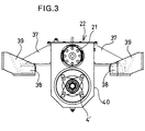
- Fig. 3 is a front elevation showing inside of a hydraulically controlled power transmission of the vehicle with the auxiliary traveling device;
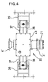
- Fig. 4 is a plan view showing inside of a hydraulically controlled power transmission of the vehicle with the auxiliary traveling device; and
- Fig. 5 is a side elevation of the vacuum type suction cleaning vehicle.
-
- The present invention will be discussed hereinafter in detail in terms of the preferred embodiment of the present invention with reference to the accompanying drawings. In the following description, numerous specific details are set forth in order to provide a thorough understanding of the present invention. It will be obvious, however, to those skilled in the art that the present invention may be practiced without these specific details. In other instance, well-known structures are not shown in detail in order to avoid unnecessarily obscure the present invention.
- One embodiment of a vehicle with an auxiliary traveling device according to the present invention will be discussed hereinafter in detail in terms of a vacuum type suction cleaning vehicle which is installed an external power takeoff and is designed for continuously collecting particulate substance such as sand or the like, and leaf-like matter such as fallen leaves, paper waste or so forth residing on a road surface.
- Fig. 1 generally shows a construction of a power transmission mechanism A of the construction discussed below.
- The
reference numeral 1 denotes a traveling prime mover, i.e. an internal combustion engine, 2 denotes a connecting and disconnecting device, i.e. a clutch, 3 denotes a primary power transmission for normal traveling provided with an external power takeoff (PTO) 3', 4 denotes a rotary power transmission A shaft (propeller shaft), 5 denotes a rotary power transmission B shaft (propeller shaft), 6 denotes a drive shaft speed reducer (differential gear box), 7 denotes a drive shaft, 8 denotes driving wheels, 9 denotes a steering wheel (handle) provided within avehicular cabin - The
reference numeral 12 denotes an external power takeoff shaft of the externalpower takeoff mechanism 3', 15 denotes a vacuum generating device forming a vacuum suction mechanism which will be discussed later. The externalpower takeoff shaft 12 and thevacuum generating device 15 are mechanically linked by V-pulleys 13 and 14 and a V-belt 23. - The
reference numeral 19 denotes a high water pressure generating device. The high waterpressure generating device 19 and the externalpower takeoff shaft 12 are mechanically linked by V-pulleys belt 24 and a connecting and disconnecting device (clutch) 18 for the high water pressure generating device. - The
reference numeral 20 denotes a hydraulic pump serving as a hydraulic pressure generator, connected to the externalpower takeoff shaft hydraulic pump transmission B shaft 5, and including thehydraulic motor 21. Thehydraulic pump 20, thehydraulic motor 21 and the hydraulically controlledpower transmission 22 for traveling at inching speed form an auxiliary traveling device B. - As shown in Figs. 2 to 4, the hydraulically controlled
power transmission 22 for traveling at inching speed in the auxiliary traveling device B is constructed by extending a rotarypower transmission shaft 34 through ahydraulic vessel 40, on which thehydraulic motor 21 is externally installed, connecting the rotary power transmission A shaft 4 and the rotary powertransmission B shaft 5 with the rotarypower transmission shaft 34 at both ends via universal joints 4' and 5', and assembling a connecting and disconnecting device (clutch) 35 for traveling at inching speed constituted of adrive disc 42 supported on the rotarypower transmission shaft 34 for free rotation with respect to the rotarypower transmission shaft 34 and adrive disc 43 fixed on the rotarypower transmission shaft 34 and operated for establishing and releasing connection by electrical operation or by pneumatic pressure in response to an electrical signal from avehicular cabin 26. - The
drive disc 42 is linked with thehydraulic motor 21 via a rotary power transmission drivengear 33 arranged integrally with thedrive disc 42 and a rotary power transmissionprimary gear 32 fixed on an output shaft 21' of thehydraulic motor 21. - The hydraulically controlled
power transmission 22 for traveling at inching speed, constructed as set forth above, is mounted at a predetermined position on a chassis by amounting beams 37, mountingmembers 38 andmounting brackets 39. - It should be noted that the reference numeral 33A in Fig. 2 denotes a hose serves for preventing drag.
- The vacuum suction mechanism is constructed with the
vacuum generating device 15 driven by revolution of the travelingprime mover 1 via the connecting and disconnectingdevice 2, the external power takeoff mechanism 3' provided on the primary power transmission 3 for normal traveling, the externalpower takeoff shaft 12, V-pulleys 13 and 14 and the V-belt 23, acollection vessel 65 connected to avacuum piping 62 and a suction piping 62' of cylindrical shape for withstanding against a vacuum force, adust catcher 63, avacuum relief valve 64, a cleaningmouth 25 utilizing a high pressure water and compressed air, and so on. Furthermore, thecollection vessel 65 can be lifted the front portion thereof about a fulcrum at the rear end by means of ahydraulic cylinder 66. A rear end of thecollection vessel 65 is opened and closed by a door which is operated by ahydraulic cylinder 67. - It should be noted that the
reference numeral 69 in Fig. 5 is a water level detector. - The vacuum type suction cleaning vehicle constructed as set forth above maintains the external power takeoff mechanism 3' and the connecting and disconnecting
device 35 for traveling at inching speed inoperative during high speed normal traveling to the destination. Thedriving wheels 8 of the vacuum type suction cleaning vehicle is rotatingly driven by the travelingprime mover 1, the connecting and disconnectingdevice 2, the primary power transmission 3 for normal traveling, the rotary power transmission A shaft 4, the rotary powertransmission B shaft 5, the drive shaft speed reducer 6, and thedrive shaft 7 for driving the vehicle in forward and reverse directions. Orientation of the driven (front)wheels 11 are controlled by thesteering wheel 9 in thevehicular cabin 26 for controlling traveling direction of the vehicle. - At this time, the connecting and disconnecting
device 35 for traveling at inching speed assembled in the hydraulically controlledpower transmission 22 for traveling at inching speed is maintained inoperative as set forth above. The rotary power transmission drivengear 33 of thedrive disc 42 will never be driven to rotate by the rotary power transmissionprimary gear 32. - During cleaning operation with inching travel of the vehicle, the connecting and disconnecting
device 35 for traveling at inching speed is made operative. In conjunction therewith, the primary power transmission 3 for normal traveling is placed at neutral range position by placing the connecting and disconnecting device in disconnecting state. At this position, thehydraulic pump 20 is driven by the travelingprime mover 1 via the external power takeoff mechanism 3' and the externalpower takeoff shaft 12. Then, by introducing the hydraulic pressure generated by thehydraulic pump 20, thehydraulic motor 21 is driven to rotatingly drive the rotarypower transmission shaft 34. According to rotation of the rotarypower transmission shaft 34, the rotary power transmission A shaft 4 as well as the rotary powertransmission B shaft 5 are rotated to rotatingly drive the drive shaft speed reducer 6, thedrive shaft 7 and thewheels 8 for travling in forward and reverse directions at the inching speed. Similarly to that upon normal traveling, orientation of the driven (front)wheels 11 are controlled by thesteering wheel 9 in thevehicular cabin 26 for controlling traveling direction of the vehicle. - In the foregoing, control for connecting and disconnecting of the
drive discs device 35 for traveling at inching speed is performed by the electrical signal from thevehicular cabin 26. If the primary power transmission 3 for normal traveling is unwantedly shifted to the position other than the neutral range position during operation of the external power takeoff mechanism 3', such shifting out of the neutral range position is detected by a not shown neutral position detector to generate an electrical signal to place the external power takeoff mechanism 3' and the connecting and disconnectingdevice 35 for traveling at inching speed inoperative position, instantly. - As can be clear from the above, the vehicle with the auxiliary traveling device according to the present invention can be driven either at the normal speed or the inching speed, selectively.
- On the other hand, since normal traveling and work by the external work implement can be performed selectively, the vehicle can be driven to travel at inching speed while the external work implement is in operation.
- Accordingly, with maintaining high revolution speed and high output of the traveling prime mover, continuous inching travel of the vehicle is permitted. Therefore, it becomes unnecessary to employ the expensive special vehicle installed with the multi-stage transmission which exhibits high speed traveling performance in normal traveling. On the other hand, it becomes possible to avoid necessity of installation of the dedicated prime mover, namely the working prime mover, separately from the traveling prime mover, resulting in high cost.
- Namely, the vehicle with the auxiliary traveling device according to the present invention can easily perform necessary operation without sacrificing high speed traveling performance which the vehicle can achieve normally, and with maintaining high revolution speed and high output of the traveling prime mover at working site.
- Furthermore, when the normal traveling primary power transmission is in neutral range position and the auxiliary traveling device is driven for driving the vehicle at inching speed, and the normal traveling primary power transmission is unwantedly shifted out of the neutral range position, such shifting out of the neutral range position is detected by a not shown neutral position detector to generate an electrical signal to place the external power takeoff and the connecting and disconnecting device for traveling at inching speed inoperative position, instantly.
- Although the present invention has been illustrated and described with respect to exemplary embodiment thereof, it should be understood by those skilled in the art that the foregoing and various other changes, omissions and additions may be made therein and thereto, without departing from the spirit and scope of the present invention. Therefore; the present invention should not be understood as limited to the specific embodiment set out above but to include all possible embodiments which can be embodied within a scope encompassed and equivalents thereof.
Claims (5)
- A vehicle with an auxiliary traveling device comprising a power train (A) including a primary power transmission (3) for normal traveling, which is connected to a prime mover (1) for normal traveling, for transmitting a rotational torque of said traveling prime mover (1) to driving wheels (8), through a rotary power transmission shaft (4), a drive shaft speed reducer (6) and drive shaft (7)
characterized byan external power takeoff mechanism (3') incorporated in said primary power transmission (3);a hydraulic pressure generator connected to an external power takeoff shaft (12) of said external power takeoff mechanism (3');a hydraulically controlled power transmission (22) for traveling at inching speed, which includes a hydraulic motor (21) connected to said hydraulic pressure generator;said power train (A) being active for enabling the vehicle to travel at a normal traveling speed while said primary power transmission (3) for normal traveling is placed at a range position other than neutral range position,said auxiliary traveling device (B) being operated for enabling travel at inching speed when said primary power transmission (3) for normal traveling is placed at neutral range position, andwhen said primary power transmission (3) for normal traveling is shifted out of said neutral range position, said external power takeoff mechanism (3) and said hydraulically controlled power transmission (22) for traveling at inching speed being made inoperative instantly in response to an electrical signal from a neutral position detector incorporated in said primary power transmission (3) for normal traveling. - A vehicle with an auxiliary traveling device which travels at a normal traveling speed by transmitting a rotational torque of a traveling prime mover (1) to driving wheels (8) via a rotary power transmission shaft (4), a drive shaft speed reducer (6) and a drive shaft (7) while a normal traveling primary power transmission is in a range other than a neutral range, and performs a required work by transmitting the rotational torque of said traveling prime mover (1) to an external work implement via an external power takeoff mechanism (3') when said normal traveling primary power transmission (3) is in said neutral range,
characterized bysaid auxiliary traveling device (B) being formed by connecting a hydraulic pressure generator to an external power takeoff shaft (12) of said external power takeoff mechanism (3') to be driven by said rotational torque of said traveling prime mover (1), and connecting a hydraulically controlled power transmission (22) for traveling at inching speed to said rotary power transmission shaft (5), said hydraulically controlled power transmission (22) for traveling at inching speed incorporating a hydraulic motor (21) connected to said hydraulic pressure generator;said auxiliary traveling device (B) being operated for enabling travel at inching speed in conjunction with operation of said external work implement when said primary power transmission (3) for normal traveling is placed at neutral range position, andwhen said primary power transmission (3) for normal traveling is shifted out of said neutral range position, said external power takeoff mechanism (3') and said hydraulically controlled power transmission (22) for traveling at inching speed being made inoperative instantly in response to an electrical signal from a neutral position detector incorporated in said primary power transmission (3) for normal traveling. - A vehicle with an auxiliary traveling device comprising a power train mechanism (A) driving said vehicle to travel at a normal traveling speed by transmitting a rotational torque of a traveling prime mover (1) to driving wheels (8) via a rotary power transmission shaft (5), a drive shaft speed reducer (6) and a drive shaft (7) while a normal traveling primary power transmission (3) is in a range other than a neutral range, and to transmit a rotational torque of said traveling prime mover (1) to an external work implement such as a vacuum generating device (15) and a high water pressure generating device (19) via an external power takeoff mechanism (3') and an external power takeoff shaft (12) for implementing a required work when said normal traveling primary power transmission (3) is in said neutral range;said auxiliary traveling device (B) being formed by connecting a hydraulic pressure generator to an external power takeoff shaft (12) of said external power takeoff mechanism (3') to be driven by said rotational torque of said traveling prime mover (1), and connecting a hydraulically controlled power transmission (22) for traveling at inching speed to said rotary power transmission shaft (5), said hydraulically controlled power transmission (22) incorporating a hydraulic motor (21) connected to said hydraulic pressure generator;said auxiliary traveling device (B) being operated for enabling travel at inching speed in conjunction with operation of said external work implement when said primary power transmission (3) for normal traveling is placed at neutral range position, andwhen said primary power transmission (3) for normal traveling is shifted out of said neutral range position, said external power takeoff mechanism (3') and said hydraulically controlled power transmission (22) for traveling at inching speed being made inoperative instantly in response to an electrical signal from a neutral position detector incorporated in said primary power transmission (3) for normal traveling.
- A vehicle with an auxiliary traveling device as set forth in any one of claims 1, 2 and 3, wherein said hydraulically controlled power transmission (22) for traveling at inching speed is constructed by extending a rotational power transmission shaft (5) through a hydraulic vessel, on which the hydraulic motor (21) is externally installed, connecting a first rotary power transmission shaft (4) and a second rotary power transmission shaft (5) with the rotary power transmission shaft (34) at both ends, and assembling a connecting and disconnecting device for traveling at inching speed constituted of a first drive disc (42) supported on the rotary power transmission shaft (4) for free rotation with respect to the rotary power transmission shaft and a second drive disc (43) fixed on the rotary power transmission shaft and operated for establishing and releasing connection by electrical signal or pneumatic pressure from a vehicular cabin (26).
- A vehicle with an auxiliary traveling device as set forth in claim 4, wherein control for connecting and disconnecting of said first and second drive discs (42, 43) in the connecting and disconnecting device (35) for traveling at inching speed is performed by an electrical signal from the vehicular cabin (26), and in response to shifting of said primary power transmission (3) for normal traveling to the position other than the neutral range position during operation of the external power takeoff, the external power takeoff and the connecting and disconnecting device for traveling at inching speed inoperative position in response to an electrical signal from a neutral position detector incorporated in said primary power transmission (3) for normal traveling, instantly .
Applications Claiming Priority (2)
| Application Number | Priority Date | Filing Date | Title |
|---|---|---|---|
| JP10281693A JP2969594B1 (en) | 1998-10-02 | 1998-10-02 | Work vehicle with auxiliary traveling device |
| JP28169398 | 1998-10-02 |
Publications (2)
| Publication Number | Publication Date |
|---|---|
| EP1002686A2 true EP1002686A2 (en) | 2000-05-24 |
| EP1002686A3 EP1002686A3 (en) | 2001-03-07 |
Family
ID=17642675
Family Applications (1)
| Application Number | Title | Priority Date | Filing Date |
|---|---|---|---|
| EP99119243A Withdrawn EP1002686A3 (en) | 1998-10-02 | 1999-09-28 | Vehicle with auxiliary traveling device |
Country Status (5)
| Country | Link |
|---|---|
| US (1) | US6269713B1 (en) |
| EP (1) | EP1002686A3 (en) |
| JP (1) | JP2969594B1 (en) |
| KR (1) | KR100347977B1 (en) |
| TW (1) | TW453956B (en) |
Cited By (1)
| Publication number | Priority date | Publication date | Assignee | Title |
|---|---|---|---|---|
| GB2378931A (en) * | 2002-03-22 | 2003-02-26 | Schuebler Fahrzeugtechnik Gmbh | Powered auxiliary element for a motor vehicle |
Families Citing this family (21)
| Publication number | Priority date | Publication date | Assignee | Title |
|---|---|---|---|---|
| US6394206B1 (en) * | 2000-10-12 | 2002-05-28 | Robert Fury | Vehicle generator control |
| US20040069544A1 (en) * | 2002-10-11 | 2004-04-15 | Brauer Daniel R. | Combined truck and delivery box auger apparatus |
| CN1330511C (en) * | 2004-08-06 | 2007-08-08 | 盐城市机床有限公司 | Special-purpose automobile chassis |
| JP4580425B2 (en) * | 2005-03-10 | 2010-11-10 | Tcm株式会社 | Hydraulic power transmission device and work vehicle |
| US7600595B2 (en) | 2005-03-14 | 2009-10-13 | Zero Emission Systems, Inc. | Electric traction |
| US7543454B2 (en) | 2005-03-14 | 2009-06-09 | Zero Emission Systems, Inc. | Method and auxiliary system for operating a comfort subsystem for a vehicle |
| US7921945B2 (en) | 2006-02-21 | 2011-04-12 | Clean Emissions Technologies, Inc. | Vehicular switching, including switching traction modes and shifting gears while in electric traction mode |
| US8565969B2 (en) | 2007-04-03 | 2013-10-22 | Clean Emissions Technologies, Inc. | Over the road/traction/cabin comfort retrofit |
| US7921950B2 (en) | 2006-11-10 | 2011-04-12 | Clean Emissions Technologies, Inc. | Electric traction retrofit |
| MX2010009878A (en) | 2008-03-19 | 2010-09-28 | Zero Emission Systems Inc | Electric traction system and method. |
| US9758146B2 (en) | 2008-04-01 | 2017-09-12 | Clean Emissions Technologies, Inc. | Dual mode clutch pedal for vehicle |
| KR200445718Y1 (en) | 2008-11-28 | 2009-08-27 | 김정규 | Multi-purposed vehicle in farming |
| US9631528B2 (en) | 2009-09-03 | 2017-04-25 | Clean Emissions Technologies, Inc. | Vehicle reduced emission deployment |
| CN102795105B (en) * | 2012-08-27 | 2015-09-30 | 新兴重工集团有限公司 | Car deceleration system laid by oil pipe |
| KR101436263B1 (en) | 2013-11-08 | 2014-08-29 | 강경숙 | Special vehicle |
| CN103738169B (en) * | 2013-12-21 | 2016-01-20 | 柳州正菱集团有限公司 | Automotive trannsmission system |
| CN106740084A (en) * | 2016-12-27 | 2017-05-31 | 苏州大方特种车股份有限公司 | Emergency driving mechanism and the vehicle with the mechanism |
| CN107187314B (en) * | 2017-05-16 | 2019-06-07 | 东风襄阳旅行车有限公司 | Electric motor coach steering pump and air compressor machine power taking system and its control method |
| KR101938208B1 (en) | 2018-12-10 | 2019-01-14 | 이텍산업 주식회사 | AWD vehicle ultra low-speed running system |
| CN110001320A (en) * | 2019-04-03 | 2019-07-12 | 山东大学 | A kind of amphibious robot |
| CN110712521A (en) * | 2019-09-24 | 2020-01-21 | 西安法士特汽车传动有限公司 | Transmission power takeoff system for pure electric vehicle and control method thereof |
Citations (3)
| Publication number | Priority date | Publication date | Assignee | Title |
|---|---|---|---|---|
| US4581949A (en) * | 1983-09-15 | 1986-04-15 | Zahnradfabrik Friedrichshafen Ag | Hydrostatic/mechanical transmission system |
| GB2215012A (en) * | 1988-02-11 | 1989-09-13 | Robert Jankel | Vehicle with optional hydraulic transmission |
| US5226497A (en) * | 1992-02-05 | 1993-07-13 | Eric Beaton | Carrier/excavator remote operating system |
Family Cites Families (7)
| Publication number | Priority date | Publication date | Assignee | Title |
|---|---|---|---|---|
| US3779608A (en) * | 1971-03-01 | 1973-12-18 | C Hatcher | Pavement cutting machine with selected drive system |
| US4441573A (en) * | 1980-09-04 | 1984-04-10 | Advanced Energy Systems Inc. | Fuel-efficient energy storage automotive drive system |
| US4566279A (en) * | 1980-09-29 | 1986-01-28 | Ab Volvo | Vehicle propulsion plant |
| DE3903877C1 (en) * | 1989-02-10 | 1990-09-13 | Friedrich Prof. Dr.-Ing. 4300 Essen De Jarchow | |
| US5165139A (en) * | 1992-02-03 | 1992-11-24 | Tecnically Engineered Cleaning Hydraulic Systems | Mobile cleaning unit |
| DE19734825C1 (en) * | 1997-08-12 | 1999-12-16 | Clark Equipment Belgium Nv | Power shift transmission for a mobile machine |
| US6082630A (en) * | 1997-12-01 | 2000-07-04 | Bohrer; Lee A. | Vehicle mounted high pressure cleaning apparatus |
-
1998
- 1998-10-02 JP JP10281693A patent/JP2969594B1/en not_active Expired - Fee Related
-
1999
- 1999-09-28 EP EP99119243A patent/EP1002686A3/en not_active Withdrawn
- 1999-09-28 TW TW088116572A patent/TW453956B/en not_active IP Right Cessation
- 1999-09-30 KR KR1019990042010A patent/KR100347977B1/en not_active IP Right Cessation
- 1999-10-01 US US09/410,090 patent/US6269713B1/en not_active Expired - Fee Related
Patent Citations (3)
| Publication number | Priority date | Publication date | Assignee | Title |
|---|---|---|---|---|
| US4581949A (en) * | 1983-09-15 | 1986-04-15 | Zahnradfabrik Friedrichshafen Ag | Hydrostatic/mechanical transmission system |
| GB2215012A (en) * | 1988-02-11 | 1989-09-13 | Robert Jankel | Vehicle with optional hydraulic transmission |
| US5226497A (en) * | 1992-02-05 | 1993-07-13 | Eric Beaton | Carrier/excavator remote operating system |
Cited By (2)
| Publication number | Priority date | Publication date | Assignee | Title |
|---|---|---|---|---|
| GB2378931A (en) * | 2002-03-22 | 2003-02-26 | Schuebler Fahrzeugtechnik Gmbh | Powered auxiliary element for a motor vehicle |
| GB2378931B (en) * | 2002-03-22 | 2003-12-03 | Schuebler Fahrzeugtechnik Gmbh | Powered auxiliary element on a motor vehicle |
Also Published As
| Publication number | Publication date |
|---|---|
| KR100347977B1 (en) | 2002-08-07 |
| TW453956B (en) | 2001-09-11 |
| KR20000028747A (en) | 2000-05-25 |
| US6269713B1 (en) | 2001-08-07 |
| EP1002686A3 (en) | 2001-03-07 |
| JP2000108715A (en) | 2000-04-18 |
| JP2969594B1 (en) | 1999-11-02 |
Similar Documents
| Publication | Publication Date | Title |
|---|---|---|
| US6269713B1 (en) | Vehicle with auxiliary traveling device | |
| US5894907A (en) | Asymmetrical drive system | |
| US7549499B2 (en) | Hydraulic hybrid four wheel drive | |
| CA2299802C (en) | Power plant for electric earth-moving and agricultural vehicles with four-wheel drive | |
| CA2623468A1 (en) | Electric powertrain for work machine | |
| KR20040077741A (en) | Working truck | |
| KR100230674B1 (en) | Travelling drive device for work vehicle | |
| US5492402A (en) | Combination trailer and self propelled vehicle | |
| US6589130B1 (en) | Driving system for industrial trucks | |
| US6336886B1 (en) | Drive unit for crawler working vehicles | |
| JP2631916B2 (en) | Management work machine | |
| JP3658725B2 (en) | Vehicle auxiliary travel device | |
| US7059442B2 (en) | Drive assembly for four-wheel drive vehicles | |
| JPH02285111A (en) | Driving device for soil-shifting machine | |
| GB2219562A (en) | Auxillary driving means in road-sweeping vehicle | |
| EP0945396A2 (en) | A vehicle with a lifting boom, having an engine inclined with respect to the longitudinal axis of the vehicle | |
| CN2325253Y (en) | Drive arrangement for vehicle | |
| JP4933387B2 (en) | Tractor | |
| JP2021104776A (en) | Service car | |
| KR102628971B1 (en) | Multi-purpose road management vehicle with selective front-wheel drive using hydraulic drive system | |
| KR100473288B1 (en) | Apparatus for transmitting auxiliary power of automobile | |
| EP0569250B1 (en) | Gear box and vehicle incorporating the gear box | |
| JP4441926B2 (en) | Rotary snowplow | |
| CN216423976U (en) | Land leveler front axle assembly and land leveler | |
| JP4064761B2 (en) | Rotary snowplow |
Legal Events
| Date | Code | Title | Description |
|---|---|---|---|
| PUAI | Public reference made under article 153(3) epc to a published international application that has entered the european phase |
Free format text: ORIGINAL CODE: 0009012 |
|
| AK | Designated contracting states |
Kind code of ref document: A2 Designated state(s): AT BE CH CY DE DK ES FI FR GB GR IE IT LI LU MC NL PT SE |
|
| AX | Request for extension of the european patent |
Free format text: AL;LT;LV;MK;RO;SI |
|
| PUAL | Search report despatched |
Free format text: ORIGINAL CODE: 0009013 |
|
| AK | Designated contracting states |
Kind code of ref document: A3 Designated state(s): AT BE CH CY DE DK ES FI FR GB GR IE IT LI LU MC NL PT SE |
|
| AX | Request for extension of the european patent |
Free format text: AL;LT;LV;MK;RO;SI |
|
| AKX | Designation fees paid | ||
| STAA | Information on the status of an ep patent application or granted ep patent |
Free format text: STATUS: THE APPLICATION IS DEEMED TO BE WITHDRAWN |
|
| 18D | Application deemed to be withdrawn |
Effective date: 20011009 |
|
| REG | Reference to a national code |
Ref country code: DE Ref legal event code: 8566 |