EP0999380A2 - Mechanical transmission with reduced ratio steps in upper transmission ratios - Google Patents
Mechanical transmission with reduced ratio steps in upper transmission ratios Download PDFInfo
- Publication number
- EP0999380A2 EP0999380A2 EP99121729A EP99121729A EP0999380A2 EP 0999380 A2 EP0999380 A2 EP 0999380A2 EP 99121729 A EP99121729 A EP 99121729A EP 99121729 A EP99121729 A EP 99121729A EP 0999380 A2 EP0999380 A2 EP 0999380A2
- Authority
- EP
- European Patent Office
- Prior art keywords
- ratios
- transmission
- group
- highest
- gear
- Prior art date
- Legal status (The legal status is an assumption and is not a legal conclusion. Google has not performed a legal analysis and makes no representation as to the accuracy of the status listed.)
- Granted
Links
Images


Classifications
-
- F—MECHANICAL ENGINEERING; LIGHTING; HEATING; WEAPONS; BLASTING
- F16—ENGINEERING ELEMENTS AND UNITS; GENERAL MEASURES FOR PRODUCING AND MAINTAINING EFFECTIVE FUNCTIONING OF MACHINES OR INSTALLATIONS; THERMAL INSULATION IN GENERAL
- F16H—GEARING
- F16H3/00—Toothed gearings for conveying rotary motion with variable gear ratio or for reversing rotary motion
- F16H3/02—Toothed gearings for conveying rotary motion with variable gear ratio or for reversing rotary motion without gears having orbital motion
- F16H3/08—Toothed gearings for conveying rotary motion with variable gear ratio or for reversing rotary motion without gears having orbital motion exclusively or essentially with continuously meshing gears, that can be disengaged from their shafts
- F16H3/087—Toothed gearings for conveying rotary motion with variable gear ratio or for reversing rotary motion without gears having orbital motion exclusively or essentially with continuously meshing gears, that can be disengaged from their shafts characterised by the disposition of the gears
- F16H3/093—Toothed gearings for conveying rotary motion with variable gear ratio or for reversing rotary motion without gears having orbital motion exclusively or essentially with continuously meshing gears, that can be disengaged from their shafts characterised by the disposition of the gears with two or more countershafts
- F16H3/095—Toothed gearings for conveying rotary motion with variable gear ratio or for reversing rotary motion without gears having orbital motion exclusively or essentially with continuously meshing gears, that can be disengaged from their shafts characterised by the disposition of the gears with two or more countershafts with means for ensuring an even distribution of torque between the countershafts
-
- Y—GENERAL TAGGING OF NEW TECHNOLOGICAL DEVELOPMENTS; GENERAL TAGGING OF CROSS-SECTIONAL TECHNOLOGIES SPANNING OVER SEVERAL SECTIONS OF THE IPC; TECHNICAL SUBJECTS COVERED BY FORMER USPC CROSS-REFERENCE ART COLLECTIONS [XRACs] AND DIGESTS
- Y10—TECHNICAL SUBJECTS COVERED BY FORMER USPC
- Y10T—TECHNICAL SUBJECTS COVERED BY FORMER US CLASSIFICATION
- Y10T74/00—Machine element or mechanism
- Y10T74/19—Gearing
- Y10T74/19219—Interchangeably locked
- Y10T74/19233—Plurality of counter shafts
-
- Y—GENERAL TAGGING OF NEW TECHNOLOGICAL DEVELOPMENTS; GENERAL TAGGING OF CROSS-SECTIONAL TECHNOLOGIES SPANNING OVER SEVERAL SECTIONS OF THE IPC; TECHNICAL SUBJECTS COVERED BY FORMER USPC CROSS-REFERENCE ART COLLECTIONS [XRACs] AND DIGESTS
- Y10—TECHNICAL SUBJECTS COVERED BY FORMER USPC
- Y10T—TECHNICAL SUBJECTS COVERED BY FORMER US CLASSIFICATION
- Y10T74/00—Machine element or mechanism
- Y10T74/19—Gearing
- Y10T74/19219—Interchangeably locked
- Y10T74/19377—Slidable keys or clutches
- Y10T74/19386—Multiple clutch shafts
- Y10T74/19405—Multiple forward and reverse
Definitions
- the present invention relates to a vehicular multiple-speed mechanical transmission system, preferably a fully or partially automated mechanical transmission system, wherein the transmission has a plurality of upper ratios having a relatively small ratio step therebetween.
- Automated mechanical transmission systems including fully automatic systems, partially automatic systems and systems which automatically implement all or part of a manually requested shift, also are well known in the prior art, as may be seen by reference to U.S. Pats. No. 4,361,060; 4,648,290; 4,596,986; 4,873,881; 5,406,861 and 5,592,851, the disclosures of which are incorporated herein by reference.
- Automatic clutch controls for such systems also are well known in the prior art, examples of which are disclosed in U.S. Pats. No. 4,081,065; 5,403,249 and 5,624,350, the disclosures of which are incorporated herein by reference.
- CVT continuously or infinitely variable transmissions
- Examples of CVTs may be seen by reference to U.S. Pats. No. 5,108,352; 5081,877 and 4,487,085.
- the advantages of a CVT is that the ratio may be continuously varied, not just in finite steps, to always cause the engine to operate at or very near the desired engine speed.
- These transmissions have not been commercially successful, especially for heavy-duty vehicles, as they tend to be limited in capacity, of unknown or unsatisfactory reliability, complicated and/or expensive.
- a mechanical transmission system preferably an at least partially automated transmission system
- a mechanical transmission system which overcomes or minimizes the drawbacks of the prior art by providing the known simplicity and reliability of mechanical countershaft or lay shaft transmissions and, in the higher, most-used ratios, the ability to emulate a CVT by operating with the engine at or very near the desired engine speed thereof.
- This is accomplished by providing a mulitple-ratio transmission, preferably a compound transmission having at least nine or more forward speed ratios, wherein the upper ratios have relatively very narrow ratio steps, such as 10% to 15% steps, as compared to the typical 30% to 40% steps in comparable prior art transmissions.
- the preferred embodiment of the present invention while not so limited, is an at least partially automated transmission system.
- a vehicular automated mechanical transmission system 10 utilizing the present invention is schematically illustrated in Fig. 1.
- Fully and partially automated mechanical transmission systems are well known in the prior art, and examples thereof may be seen by reference to aforementioned U.S. Pats. No. 4,361,060; 4,595,986; 4,648,290; 4,873,881; 5,406,861 and 5,592,851.
- Vehicular automated mechanical transmission system 10 includes a fuel-controlled engine 12, such as a well-known electronically controlled diesel engine, which drives a compound mechanical transmission 14 through a coupling, such as a friction master clutch 16.
- the engine 12 includes an output member 18, which drives the input members 16A of the master clutch 16, which are selectively engaged to and disengaged from the output members 16B, which are carried on the transmission input shaft 20.
- the output shaft 22 of transmission 14 is adapted for driving connection to an appropriate vehicle component, such as the differential of a drive axle 24, a transfer case or the like, as is well known in the prior art.
- Automated transmission system 10 also may include an engine controller 26, a clutch actuator 28 and a transmission actuator 30.
- Clutch 16 may be totally automatically controlled, may be automatically controlled except for start-from-stop operation, or may be entirely manually controlled.
- Actuators 26, 28 and/or 30 preferably accept command output signals 32 from and/or provide input signals 34 to a microprocessor-based control unit 36.
- Sensors 38, 40 and 42 may be utilized to provide input signals indicative of the rotational speed of the engine 12, transmission input shaft 20 and transmission output shaft 22, respectively.
- Various other devices such as a driver control console 44 and a throttle position sensor 46, may be utilized to provide input signals to the controller 36.
- System 10 will also include sources (not shown) of electrical, pneumatic and/or hydraulic power.
- the sensors 38, 40, 42, 44 and 46 may be of any known type of construction for generating analog or digital signals proportional to the parameters monitored thereby.
- operators 26, 28 and 30 may be of any known electric, pneumatic or electropneumatic type for executing operations in response to command output signals 32 from the central processing unit 36.
- the central processing unit may be provided with circuitry for differentiating the input signals from the sensors to provide a calculated signal indicative of the rate of change thereof.
- the processing unit 36 also may be provided with circuitry, logic rules and/or stored data for comparison of the input signals from sensors 40 and 42 to verify and/or identify that the transmission 14 is engaged in a particular gear ratio.
- the various sensors, actuators and control unit 36 may communicate over an electronic data link conforming to an industry standard, such as SAE J-1922, SAE J-1939 or ISO 11898.
- Transmission 14 is a compound mechanical transmission comprising a main transmission section 50 connected in series with an auxiliary transmission section 52.
- Auxiliary transmission section 52 includes a splitter section 52A and a range section 52B, the structural details and advantages of which are disclosed in aforementioned U.S. Pats. No. 4,754,665 and 5,390,561.
- the input shaft 20 carries an input gear 54 for simultaneously driving a plurality of substantially identical main section countershaft assemblies 56 and 56A at substantially identical rotational speeds.
- the two substantially identical main section countershaft assemblies are provided on the diametrically opposite sides of a main shaft 58, which is generally coaxially aligned with input shaft 20 and output shaft 22.
- Each of the countershaft assemblies comprises a countershaft 60 supported by bearings (not shown) in a transmission housing (not shown).
- Each of the countershafts is provided with an identical grouping of countershaft gears 62, 64, 66, 68, 70 and 72, fixed for rotation therewith.
- a plurality of main shaft gears 74, 76, 78, 80 and 82 surround the main shaft 58 and are selectively clutchable, one at a time, to the main shaft 58 for rotation therewith by sliding jaw clutch collars 84, 86 and 88, as is well known in the prior art.
- Clutch collar 84 also may be used to clutch input gear 54 to main shaft 58 to provide a direct driving relationship between the input shaft 20 and the main shaft 58.
- sliding clutch collars 84, 86 and 88 are axially positioned by means of shift forks (not shown) associated with the acuator 30.
- Clutch collars 84, 86 and 88 may be of any well-known, double-acting, non-synchronized or synchronized jaw clutch type.
- Main section main shaft gear 82 is the reverse gear and is in continuous meshing engagement with countershaft gear 72 by means of conventional intermediate idler gears (not shown).
- sliding jaw clutches 84, 86 and 88 are 3-position clutches in that they may be positioned in a centered, non-engaged position, as illustrated, or in a fully rightwardly engaged or fully leftwardly engaged position.
- Auxiliary transmission section 52 includes two substantially identical auxiliary countershaft assemblies 90 and 90A, each comprising an auxiliary countershaft 92 supported by bearings (not shown) in the transmission housing (not shown) and carrying three auxiliary section countershaft gears 94, 96 and 98 fixed for rotation therewith.
- Auxiliary countershaft gears 94 are constantly meshed with and support auxiliary section splitter gear 100, which surrounds main shaft 58.
- Auxiliary countershaft gears 96 are constantly meshed with and support auxiliary section splitter/range gear 102, which surrounds the output shaft 22 at the end thereof adjacent the coaxial rear end of main shaft 56.
- Auxiliary section countershaft gears 98 are constantly meshed with and support auxiliary section range gear 104, which surrounds the output shaft 22.
- a sliding 2-position jaw clutch collar 106 is fixed to the main shaft 58 for rotation therewith and is utilized to selectively couple either the splitter gear 100 or the splitter/range gear 102 to the main shaft 58, while a 2-position synchronized jaw clutch assembly 108 is fixed to the output shaft 22 for rotation therewith and is utilized to selectively couple either the splitter/range gear 102 or the range gear 104 to the output shaft 22.
- sliding clutch 106 is utilized to determine the gear ratio of splitter section 52A
- sliding synchronized clutch assembly 108 is utilized to determine the ratio of the range section 52B of the auxiliary section 52.
- the auxiliary section 52 thus defines three gear layers and provides four selectable ratios for the auxiliary section 52.
- transmission 14 has a main transmission section 50 providing five potential forward speed ratios and auxiliary transmission section 52 provides four potential transmission ratios, which would yield a theoretically available twenty forward speed ratios, only twelve of the theoretically available ratios are practically utilized for the transmission system of the present invention.
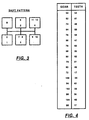
- Fig. 3 illustrates the shift pattern utilized to obtain the twelve forward speeds and and reverse ratios for the transmission 14 of the present invention.
- the shift pattern necessary to obtain the twelve forward speed ratios is a non-standard shift pattern and is best implemented in an at least partially automated transmission system wherein the transmission shift actuator 30 operating under command output signals 32 will shift the transmission automatically in response to shift requests generated by the controller logic and/or requested by the operator via the control module 44.
- operator control module 44 includes both a "D" position wherein gear ratios are automatically selected by the controller logic and an "H" position wherein the operator may manually select up- and downshifts, which are then automatically implemented in accordance with output signals issued by controller 36.
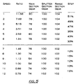
- Fig. 4 illustrates the gear teeth on each of the gears of transmission 14, while Fig. 5 illustrates the various ratios between input and output shaft rotational speed for each transmission forward speed ratio, indicates which of the main section, splitter section and range section gears are engaged for each speed ratio, and indicates the percentage step between the adjacent speed ratios.
- the ratio steps usually are generally equal between the speed ratios throughout the entire ratio coverage of the transmission and average about 30% to 40% steps.
- the ratio steps in the lower grouping of ratios i.e., the first through sixth ratio steps
- the ratio steps between the seventh and twelfth forward speeds averages about 13% steps.
- These upper ratios, seventh through twelfth forward speeds represent a high percentage of vehicle operation and are the speed ratios utilized by a heavy-duty vehicle in operation between about 35 mph and 70 mph.
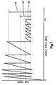
- Fig. 6 is a schematic illustration, not necessarily in accurate proportion, of the advantages of the present invention.
- line 112 represents the peak efficiency engine speed at various sensed parameters (such as, for example, throttle position).
- Lines 114 will represent upshift and downshift points for a transmission having about a 40% step, while lines 116 will represent the upshift and downshift points for a transmission having ratio steps of about 13%.
- the transmission will operate in a much smaller band 118 of engine speeds about the peak efficiency engine speed 112, as compared to the band 120 of engine speeds operated in for transmissions having ratio steps in accordance with the typical prior art.
- transmission 14 when operating in the upper range of ratios, transmission 14 will be operating at or very close to the peak efficiency engine speed and, thus, emulate the advantage obtained by utilizing a CVT-type transmission.
- Range 130 represents the operating range of engine speed of transmission 14 in the highest range (seventh-twelfth) of ratios, while ranges 132 and 134 represent typical ranges in a conventional 14-16 speed transmission and 10-speed transmission, respectively.
- a transmission automated in only the two upper ratios may utilize only a reduced ratio step in the upper two ratios.
- the present invention provides a relatively simple and inexpensive transmission system having the reliability and capacity associated with mechanical transmissions and also providing the advantages associated with the use of continuously variable transmissions.
Landscapes
- Engineering & Computer Science (AREA)
- General Engineering & Computer Science (AREA)
- Mechanical Engineering (AREA)
- Control Of Transmission Device (AREA)
- Structure Of Transmissions (AREA)
- Lubricants (AREA)
Abstract
Description
- The present invention relates to a vehicular multiple-speed mechanical transmission system, preferably a fully or partially automated mechanical transmission system, wherein the transmission has a plurality of upper ratios having a relatively small ratio step therebetween.
- Multiple-speed vehicular mechanical transmissions for heavy-duty vehicles having 9, 10, 12, 13, 16, 18 or more forward gear ratios are well known in the prior art, as may be seen by reference to U.S. Pats. No. 4,754,665; 5,390,561 and 5,546,823, the disclosures of which are incorporated herein by reference. Such transmissions typically provided a relatively equal ratio step (i.e., the percentage change in ratio between adjacent ratios) across the entire ratio coverage (i.e., the difference between the highest and lowest speed forward ratios). The ratio steps were a compromise between providing a drivable vehicle and a desire to be in a ratio that will allow the engine to operate at or near a most fuel-efficient or otherwise desirable engine speed.
- Automated mechanical transmission systems, including fully automatic systems, partially automatic systems and systems which automatically implement all or part of a manually requested shift, also are well known in the prior art, as may be seen by reference to U.S. Pats. No. 4,361,060; 4,648,290; 4,596,986; 4,873,881; 5,406,861 and 5,592,851, the disclosures of which are incorporated herein by reference. Automatic clutch controls for such systems also are well known in the prior art, examples of which are disclosed in U.S. Pats. No. 4,081,065; 5,403,249 and 5,624,350, the disclosures of which are incorporated herein by reference.
- So-called continuously or infinitely variable transmissions ("CVT") for vehicular use also are known in the prior art. Examples of CVTs may be seen by reference to U.S. Pats. No. 5,108,352; 5081,877 and 4,487,085. The advantages of a CVT is that the ratio may be continuously varied, not just in finite steps, to always cause the engine to operate at or very near the desired engine speed. These transmissions have not been commercially successful, especially for heavy-duty vehicles, as they tend to be limited in capacity, of unknown or unsatisfactory reliability, complicated and/or expensive.
- In accordance with the present invention, a mechanical transmission system, preferably an at least partially automated transmission system, is provided which overcomes or minimizes the drawbacks of the prior art by providing the known simplicity and reliability of mechanical countershaft or lay shaft transmissions and, in the higher, most-used ratios, the ability to emulate a CVT by operating with the engine at or very near the desired engine speed thereof. This is accomplished by providing a mulitple-ratio transmission, preferably a compound transmission having at least nine or more forward speed ratios, wherein the upper ratios have relatively very narrow ratio steps, such as 10% to 15% steps, as compared to the typical 30% to 40% steps in comparable prior art transmissions.
- As providing such a transmission system may require a non-traditional shift pattern (i.e., not a typical multiple-H or repeat-H type shift pattern) and/or more frequent than typically expected shifting in the upper ratios, the preferred embodiment of the present invention, while not so limited, is an at least partially automated transmission system.
- Accordingly, it is an object of the present invention to provide a relatively simple, inexpensive and reliable mechanical transmission system suitable for heavy vehicle usage, preferably an automated mechanical transmission system, which in the higher gear ratios will emulate a CVT.
- This and other objects and advantages of the present invention will become apparent from a reading of the following description of the preferred embodiment taken in connection with the attached drawings.
-
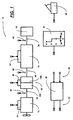
- Fig. 1 is a schematic illustration of an automated mechanical transmission system according to the present invention.
- Fig. 2 is a schematic illustration of a mechanical transmission according to the present invention.
- Fig. 3 is a schematic illustration of the shift pattern for the transmission of Fig. 2.
- Fig. 4 is a chart illustrating the number of gear teeth on the gears of the transmission of Fig. 2.
- Fig. 5 is a chart illustrating the ratios, engaged gears of each forward speed and ratio step between the forward speed ratios of the transmission of Fig. 2.
- Fig. 6 is a graphical representation of the present invention.
- Fig. 7 is a chart illustrating the shift points for the transmission of Fig. 2.
-
- Certain terminology will be used in the following description for convenience only and will not be limiting. The words "upwardly," "downwardly," "rightwardly' and "leftwardly" will designate directions in the directions to which reference is made. The words "inwardly" and "outwardly" will refer respectively to directions toward and away from the geometric center of the device and designated parts thereof. Said terminology will include the words above specifically mentioned, derivatives thereof and words of similar import.
- A vehicular automated
mechanical transmission system 10 utilizing the present invention is schematically illustrated in Fig. 1. Fully and partially automated mechanical transmission systems are well known in the prior art, and examples thereof may be seen by reference to aforementioned U.S. Pats. No. 4,361,060; 4,595,986; 4,648,290; 4,873,881; 5,406,861 and 5,592,851. - Vehicular automated
mechanical transmission system 10 includes a fuel-controlledengine 12, such as a well-known electronically controlled diesel engine, which drives a compoundmechanical transmission 14 through a coupling, such as afriction master clutch 16. Theengine 12 includes anoutput member 18, which drives theinput members 16A of themaster clutch 16, which are selectively engaged to and disengaged from theoutput members 16B, which are carried on thetransmission input shaft 20. Theoutput shaft 22 oftransmission 14 is adapted for driving connection to an appropriate vehicle component, such as the differential of adrive axle 24, a transfer case or the like, as is well known in the prior art.Automated transmission system 10 also may include anengine controller 26, aclutch actuator 28 and atransmission actuator 30. Clutch 16 may be totally automatically controlled, may be automatically controlled except for start-from-stop operation, or may be entirely manually controlled.Actuators command output signals 32 from and/or provideinput signals 34 to a microprocessor-basedcontrol unit 36.Sensors engine 12,transmission input shaft 20 andtransmission output shaft 22, respectively. Various other devices, such as adriver control console 44 and athrottle position sensor 46, may be utilized to provide input signals to thecontroller 36.System 10 will also include sources (not shown) of electrical, pneumatic and/or hydraulic power. - Drive train components and controls therefor of the type described above are known in the prior art and may be appreciated in greater detail by reference to U.S. Pats. No. 4,595,786; 4,576,065; 4,445,393 and 4,850,236. The
sensors operators command output signals 32 from thecentral processing unit 36. In addition to the direct inputs to the central processing unit, the central processing unit may be provided with circuitry for differentiating the input signals from the sensors to provide a calculated signal indicative of the rate of change thereof. Theprocessing unit 36 also may be provided with circuitry, logic rules and/or stored data for comparison of the input signals fromsensors transmission 14 is engaged in a particular gear ratio. - As is known, the various sensors, actuators and
control unit 36 may communicate over an electronic data link conforming to an industry standard, such as SAE J-1922, SAE J-1939 or ISO 11898. - The structural details of compound
mechanical transmission 14 are schematically illustrated in Fig. 2. Transmissions similar to themechanical compound transmission 14 are well known in the prior art and may be appreciated by reference to U.S. Pats. No. 3,105,395 and 3,283,613, the disclosures of which are incorporated herein by reference, as well as by reference to aforementioned U.S. Pats. No. 4,754,665; 5,390,561 and 5,546,823. -
Transmission 14 is a compound mechanical transmission comprising amain transmission section 50 connected in series with anauxiliary transmission section 52.Auxiliary transmission section 52 includes asplitter section 52A and arange section 52B, the structural details and advantages of which are disclosed in aforementioned U.S. Pats. No. 4,754,665 and 5,390,561. - In
main transmission section 50, theinput shaft 20 carries aninput gear 54 for simultaneously driving a plurality of substantially identical mainsection countershaft assemblies main shaft 58, which is generally coaxially aligned withinput shaft 20 andoutput shaft 22. Each of the countershaft assemblies comprises acountershaft 60 supported by bearings (not shown) in a transmission housing (not shown). Each of the countershafts is provided with an identical grouping ofcountershaft gears main shaft 58 and are selectively clutchable, one at a time, to themain shaft 58 for rotation therewith by sliding jawclutch collars Clutch collar 84 also may be used toclutch input gear 54 tomain shaft 58 to provide a direct driving relationship between theinput shaft 20 and themain shaft 58. - Typically, sliding
clutch collars acuator 30.Clutch collars - Main section
main shaft gear 82 is the reverse gear and is in continuous meshing engagement withcountershaft gear 72 by means of conventional intermediate idler gears (not shown). As is known, slidingjaw clutches -
Auxiliary transmission section 52 includes two substantially identicalauxiliary countershaft assemblies auxiliary countershaft 92 supported by bearings (not shown) in the transmission housing (not shown) and carrying three auxiliary section countershaft gears 94, 96 and 98 fixed for rotation therewith. Auxiliary countershaft gears 94 are constantly meshed with and support auxiliarysection splitter gear 100, which surroundsmain shaft 58. Auxiliary countershaft gears 96 are constantly meshed with and support auxiliary section splitter/range gear 102, which surrounds theoutput shaft 22 at the end thereof adjacent the coaxial rear end ofmain shaft 56. Auxiliary section countershaft gears 98 are constantly meshed with and support auxiliarysection range gear 104, which surrounds theoutput shaft 22. A sliding 2-position jawclutch collar 106 is fixed to themain shaft 58 for rotation therewith and is utilized to selectively couple either thesplitter gear 100 or the splitter/range gear 102 to themain shaft 58, while a 2-position synchronized jawclutch assembly 108 is fixed to theoutput shaft 22 for rotation therewith and is utilized to selectively couple either the splitter/range gear 102 or therange gear 104 to theoutput shaft 22. Accordingly, slidingclutch 106 is utilized to determine the gear ratio ofsplitter section 52A, while sliding synchronizedclutch assembly 108 is utilized to determine the ratio of therange section 52B of theauxiliary section 52. As more fully described in aforementioned U.S. Pats. No. 4,754,665 and 5,390,561, theauxiliary section 52 thus defines three gear layers and provides four selectable ratios for theauxiliary section 52. - Although
transmission 14 has amain transmission section 50 providing five potential forward speed ratios andauxiliary transmission section 52 provides four potential transmission ratios, which would yield a theoretically available twenty forward speed ratios, only twelve of the theoretically available ratios are practically utilized for the transmission system of the present invention. - Fig. 3 illustrates the shift pattern utilized to obtain the twelve forward speeds and and reverse ratios for the
transmission 14 of the present invention. As may be seen, the shift pattern necessary to obtain the twelve forward speed ratios is a non-standard shift pattern and is best implemented in an at least partially automated transmission system wherein thetransmission shift actuator 30 operating under command output signals 32 will shift the transmission automatically in response to shift requests generated by the controller logic and/or requested by the operator via thecontrol module 44. It is noted thatoperator control module 44 includes both a "D" position wherein gear ratios are automatically selected by the controller logic and an "H" position wherein the operator may manually select up- and downshifts, which are then automatically implemented in accordance with output signals issued bycontroller 36. - Fig. 4 illustrates the gear teeth on each of the gears of
transmission 14, while Fig. 5 illustrates the various ratios between input and output shaft rotational speed for each transmission forward speed ratio, indicates which of the main section, splitter section and range section gears are engaged for each speed ratio, and indicates the percentage step between the adjacent speed ratios. - In a typical 10-, 12-, 16- or 18-forward-speed transmission for a heavy-duty vehicle, the ratio steps usually are generally equal between the speed ratios throughout the entire ratio coverage of the transmission and average about 30% to 40% steps. As may be seen by reference to Fig. 5, the ratio steps in the lower grouping of ratios, i.e., the first through sixth ratio steps, are considerably larger than the ratio steps in the higher group of speeds, i.e., seventh through twelfth speeds, of
transmission 14. The ratio steps between the seventh and twelfth forward speeds averages about 13% steps. These upper ratios, seventh through twelfth forward speeds, represent a high percentage of vehicle operation and are the speed ratios utilized by a heavy-duty vehicle in operation between about 35 mph and 70 mph. By providing the relatively narrow ratio steps in this higher range of ratios, the vehicle will spend a high percentage of its operation operating at or very near the peak efficiency engine speed for the vehicle power train. - Fig. 6 is a schematic illustration, not necessarily in accurate proportion, of the advantages of the present invention. Assuming that
line 112 represents the peak efficiency engine speed at various sensed parameters (such as, for example, throttle position).Lines 114 will represent upshift and downshift points for a transmission having about a 40% step, whilelines 116 will represent the upshift and downshift points for a transmission having ratio steps of about 13%. By utilizing relatively smaller ratio steps, the transmission will operate in a muchsmaller band 118 of engine speeds about the peakefficiency engine speed 112, as compared to theband 120 of engine speeds operated in for transmissions having ratio steps in accordance with the typical prior art. Thus, when operating in the upper range of ratios,transmission 14 will be operating at or very close to the peak efficiency engine speed and, thus, emulate the advantage obtained by utilizing a CVT-type transmission. - The shift points for
transmission 14 are illustrated in Fig. 7.Range 130 represents the operating range of engine speed oftransmission 14 in the highest range (seventh-twelfth) of ratios, whileranges - In an alternate embodiment, a transmission automated in only the two upper ratios (i.e., a "Top-2" type transmission) (see, for example, U.S. Pats. no. 4,722,248 and 4,850,236) may utilize only a reduced ratio step in the upper two ratios.
- Accordingly, the present invention provides a relatively simple and inexpensive transmission system having the reliability and capacity associated with mechanical transmissions and also providing the advantages associated with the use of continuously variable transmissions.
- Although the present invention has been described with a certain degree of particularity, it is understood that the description of the preferred embodiment is by way of example only and that numerous changes to form and detail are possible without departing from the spirit and scope of the invention as hereinafter claimed.
Claims (16)
- A vehicular mechanical change-gear transmission having a plurality of selectable ratios comprising a lower group of ratios for low-speed operation and an upper group of at least three ratios for highest-speed operation, the average ratio step between the ratios in said upper group of ratios being smaller than the average ratio steps between the ratios in the lower group of ratios.
- The transmission of claim 1 wherein the average ratio step between the ratios in said upper group of ratios is about 10% to 20% and the average ratio step between the ratios in said lower group of ratios is about 30% to 50%.
- A vehicular mechanical change-gear transmission having at least eight selectable ratios comprising a lower group of at least four ratios for low-speed operation and an upper group of at least three ratios for highest-speed operation, the average ratio step between the ratios in said upper group of ratios being at least 50% smaller than the average ratio steps between the ratios in the lower group of ratios.
- The transmission of claim 3 wherein the average ratio step between the ratios in said upper group of ratios is about 10% to 20% and the average ratio step between the ratios in said lower group of ratios is about 30% to 50%.
- The transmission of claim 3 wherein said transmission is a compound transmission having ten or more ratios.
- The transmission of claim 5 wherein said upper group of ratios has four or more ratios and is intended for vehicle operation at speeds of about 35 mph to 65 mph or greater.
- An automated vehicular mechanical transmission system (10) comprising a fuel-controlled engine (12) drivingly connected to a mechanical transmission (14) by a coupling (16), and an electronic processor (36) for receiving input signals (34) and processing same according to logic rules to issue command output signals (32) to system actuators (26, 28, 30), said system characterized by:said transmission having a plurality of selectable ratios (first-twelfth) comprising a lower group of ratios (first-sixth) for low-speed operation and an upper group of at least three ratios (seventh-twelfth) for highest-speed operation, the average ratio step between the ratios in said upper group of ratios being smaller than the average ratio steps between the ratios in the lower group of ratios.
- The system of claim 7 wherein the average ratio step between the ratios in said upper group of ratios is about 10% to 20% and the average ratio step between the ratios in said lower group of ratios is about 30% to 50%.
- The transmission of claim 7 wherein said transmission is a compound transmission having ten or more ratios.
- The transmission of claim 9 wherein said upper group of ratios has four or more ratios and is intended for vehicle operation at speeds of about 35 mph to 65 mph or greater.
- The system of claim 10 wherein said transmission has a non-H-type shift pattern.
- A partially automated vehicular mechanical transmission system comprising a vehicular transmission having a plurality of groups of forward gear ratios ranging from a first group including a lowest gear ratio to a highest group including a highest gear ratio with each of said groups having a gear ratio manually selectable by an operator and with at least said highest group including a plurality of sequentially related highest gear ratios, said transmission including actuator means enabling automatic shifting between the highest sequentially related gear ratios of at least said highest group, and said control system including means for sensing when one of the sequentially related highest gear ratios of said highest group is manually selected by the operator and operable to enable the actuator means to effect automatic shifting between the sequentially related highest gear ratios within said highest group when one of the sequentially related highest gear ratios within said group is manually selected by the operator, the gear ratios of said first group requiring manual selection by the operator, said system characterized by:the average ratio step between the ratios within said highest group being at least 50% smaller than the average ratio step in said first group.
- The system of claim 12 wherein the average ratio step between the ratios in said upper group of ratios is about 10% to 20% and the average ratio step between the ratios in said lower group of ratios is about 30% to 50%.
- The transmission of claim 12 wherein said transmission is a compound transmission having ten or more ratios.
- The system of claim 12 wherein said vehicular transmission is a compound transmission having a main section connected in series with an auxiliary section including splitter gearing, said manual selection of one of the sequentially related highest gear ratios of said highest group comprising a main section gear ratio change and said automatic shifting between the highest sequentially related gear ratios within said highest group comprising only auxiliary section shifting.
- The system of claim 15 wherein the gear ratios of all but the highest group require manual selection and engagement by the operator.
Applications Claiming Priority (2)
| Application Number | Priority Date | Filing Date | Title |
|---|---|---|---|
| US185131 | 1998-11-03 | ||
| US09/185,131 US6085606A (en) | 1998-11-03 | 1998-11-03 | Mechanical transmission with reduced ratio steps in upper transmission ratios |
Publications (3)
| Publication Number | Publication Date |
|---|---|
| EP0999380A2 true EP0999380A2 (en) | 2000-05-10 |
| EP0999380A3 EP0999380A3 (en) | 2000-12-06 |
| EP0999380B1 EP0999380B1 (en) | 2004-01-21 |
Family
ID=22679731
Family Applications (1)
| Application Number | Title | Priority Date | Filing Date |
|---|---|---|---|
| EP99121729A Expired - Lifetime EP0999380B1 (en) | 1998-11-03 | 1999-11-03 | Mechanical transmission with reduced ratio steps in upper transmission ratios |
Country Status (5)
| Country | Link |
|---|---|
| US (1) | US6085606A (en) |
| EP (1) | EP0999380B1 (en) |
| CN (1) | CN1201100C (en) |
| BR (1) | BR9907311A (en) |
| DE (1) | DE69914284T2 (en) |
Cited By (2)
| Publication number | Priority date | Publication date | Assignee | Title |
|---|---|---|---|---|
| DE10025684A1 (en) * | 2000-05-24 | 2001-11-29 | Zahnradfabrik Friedrichshafen | Group construction discrete gearbox allows highest gear of main group to be selected in only one gear of range group,with ratio change to main group highest gear being much smaller than others |
| CN103968010A (en) * | 2014-04-30 | 2014-08-06 | 陕西法士特齿轮有限责任公司 | Twelve-gear electronic control mechanical type automatic transmission |
Families Citing this family (11)
| Publication number | Priority date | Publication date | Assignee | Title |
|---|---|---|---|---|
| DE10143994A1 (en) * | 2001-09-07 | 2003-03-27 | Zahnradfabrik Friedrichshafen | Modular gear system comprises three gear groups of two-gear group, multiple gear basic group and multiple outlet side group, and reverse gear cogs |
| NL1019109C2 (en) * | 2001-10-04 | 2003-04-07 | Hamapro Holding B V | Gear squaring. |
| US6702713B2 (en) * | 2001-12-21 | 2004-03-09 | Eaton Corporation | Shift strategies for mock continuously variable transmission |
| US6979279B2 (en) * | 2003-09-29 | 2005-12-27 | Eaton Corporation | Range control method for lever shifted compound transmissions |
| US7013756B2 (en) * | 2004-02-27 | 2006-03-21 | Zf Meritor, Llc | Transmission with deep reduction low range splitter gear |
| CN2835704Y (en) * | 2005-10-28 | 2006-11-08 | 陕西法士特齿轮有限责任公司 | Master and slave cases structured automobile transmission with double middle shafts and twelve gearshifts |
| CN101487519B (en) * | 2008-09-18 | 2015-03-25 | 孟良吉 | Full-gear speed self-adapting continuously variable transmission |
| RU2514623C2 (en) * | 2009-09-14 | 2014-04-27 | Сканиа Св Аб | Method of control of gearbox |
| AU2010362658B2 (en) * | 2010-10-18 | 2014-12-04 | Volvo Truck Corporation | Heavy duty truck transmission with triple overdrive |
| DE102017201607A1 (en) * | 2017-02-01 | 2018-08-02 | Zf Friedrichshafen Ag | Transmission and method for operating an automatic transmission |
| DE102017204336A1 (en) | 2017-03-15 | 2018-09-20 | Wirtgen Gmbh | Soil cultivation machine with manual transmission between drive motor and rotatable working device |
Citations (10)
| Publication number | Priority date | Publication date | Assignee | Title |
|---|---|---|---|---|
| US4081065A (en) | 1976-12-23 | 1978-03-28 | Smyth Robert Ralston | Controlled power clutch |
| US4361060A (en) | 1978-01-24 | 1982-11-30 | Smyth Robert Ralston | Mechanical automatic transmission |
| US4596986A (en) | 1983-08-29 | 1986-06-24 | The United States Of America As Represented By The Secretary Of The Navy | Sidelobe canceller with adaptive antenna subarraying using a weighted Butler matrix |
| US4648290A (en) | 1984-07-23 | 1987-03-10 | Eaton Corporation | Semi-automatic mechanical transmission control |
| US4754665A (en) | 1986-02-05 | 1988-07-05 | Eaton Corporation | Auxiliary transmission section |
| US4873881A (en) | 1989-01-06 | 1989-10-17 | Eaton Corporation | Electrically actuated x-y shifting mechanism |
| US5390561A (en) | 1993-05-20 | 1995-02-21 | Eaton Corporation | Compound transmission |
| US5406861A (en) | 1993-09-22 | 1995-04-18 | Eaton Corporation | Manual modification of automatic mode shift points |
| US5546823A (en) | 1993-05-20 | 1996-08-20 | Eaton Corporation | High-capacity compound transmission |
| US5592851A (en) | 1994-11-11 | 1997-01-14 | Eaton Corporation | Semi-automatic mechanical transmission with forced automatic shifting |
Family Cites Families (20)
| Publication number | Priority date | Publication date | Assignee | Title |
|---|---|---|---|---|
| DE2445241C2 (en) * | 1974-09-21 | 1982-11-04 | Fichtel & Sachs Ag, 8720 Schweinfurt | Manual transmissions for automobiles |
| US4595986A (en) * | 1984-10-09 | 1986-06-17 | Eaton Corporation | Method for control of automatic mechanical transmission system utilizing a microprocessor based electronic controller |
| US4614133A (en) * | 1984-10-12 | 1986-09-30 | Caterpillar Inc. | Vehicle transmission having countershaft and planetary portions |
| EP0268582B1 (en) * | 1985-07-06 | 1990-01-31 | ZF FRIEDRICHSHAFEN Aktiengesellschaft | Transmission |
| US4722248A (en) * | 1986-04-11 | 1988-02-02 | Eaton Corporation | Transmission shift control system |
| DE3618515C2 (en) * | 1986-06-02 | 1998-05-07 | Klaue Hermann | Clutch-connected multi-step transmission for motor vehicles |
| US4788889A (en) * | 1987-03-19 | 1988-12-06 | Eaton Corporation | Mechanical transmission and control method therefor |
| US4876924A (en) * | 1987-09-21 | 1989-10-31 | Eaton Corporation | Extended range splitter type compound transmission |
| US4850236A (en) * | 1987-11-20 | 1989-07-25 | Eaton Corporation | Vehicle drive line shift control system and method |
| US5117702A (en) * | 1991-05-28 | 1992-06-02 | Deere & Company | Powershift transmission for an agricultural tractor |
| US5403249A (en) * | 1991-10-07 | 1995-04-04 | Eaton Corporation | Method and apparatus for robust automatic clutch control |
| US5394772A (en) * | 1993-05-14 | 1995-03-07 | Eaton Corporation | Compound transmission having double splitter gear auxiliary section |
| CA2123660C (en) * | 1993-05-14 | 2000-06-13 | Alan Charles Stine | Compound transmission having deep reduction auxiliary section gear |
| US5421222A (en) * | 1993-05-14 | 1995-06-06 | Eaton Corporation | Compound transmission having auto range actuation through dual entry first speed gear |
| US5385066A (en) * | 1993-07-01 | 1995-01-31 | Eaton Corporation | Multiple ratio transmission |
| GB9421350D0 (en) * | 1994-10-24 | 1994-12-07 | Eaton Corp | Automated clutch control and calibration |
| US5557978A (en) * | 1995-03-07 | 1996-09-24 | Deere & Company | Countershaft power transmission |
| US5653143A (en) * | 1995-06-06 | 1997-08-05 | Langevin; David W. | Automatic mechanical variable ratio transmission |
| US5679096A (en) * | 1996-04-08 | 1997-10-21 | Eaton Corporation | Torque control for powertrain and change-gear transmission utilized in same |
| AU2559299A (en) * | 1998-01-16 | 1999-08-02 | Joachim Horsch | Multispeed powershift transmission |
-
1998
- 1998-11-03 US US09/185,131 patent/US6085606A/en not_active Expired - Lifetime
-
1999
- 1999-11-03 DE DE69914284T patent/DE69914284T2/en not_active Expired - Lifetime
- 1999-11-03 CN CNB991260279A patent/CN1201100C/en not_active Expired - Fee Related
- 1999-11-03 BR BR9907311-0A patent/BR9907311A/en not_active IP Right Cessation
- 1999-11-03 EP EP99121729A patent/EP0999380B1/en not_active Expired - Lifetime
Patent Citations (10)
| Publication number | Priority date | Publication date | Assignee | Title |
|---|---|---|---|---|
| US4081065A (en) | 1976-12-23 | 1978-03-28 | Smyth Robert Ralston | Controlled power clutch |
| US4361060A (en) | 1978-01-24 | 1982-11-30 | Smyth Robert Ralston | Mechanical automatic transmission |
| US4596986A (en) | 1983-08-29 | 1986-06-24 | The United States Of America As Represented By The Secretary Of The Navy | Sidelobe canceller with adaptive antenna subarraying using a weighted Butler matrix |
| US4648290A (en) | 1984-07-23 | 1987-03-10 | Eaton Corporation | Semi-automatic mechanical transmission control |
| US4754665A (en) | 1986-02-05 | 1988-07-05 | Eaton Corporation | Auxiliary transmission section |
| US4873881A (en) | 1989-01-06 | 1989-10-17 | Eaton Corporation | Electrically actuated x-y shifting mechanism |
| US5390561A (en) | 1993-05-20 | 1995-02-21 | Eaton Corporation | Compound transmission |
| US5546823A (en) | 1993-05-20 | 1996-08-20 | Eaton Corporation | High-capacity compound transmission |
| US5406861A (en) | 1993-09-22 | 1995-04-18 | Eaton Corporation | Manual modification of automatic mode shift points |
| US5592851A (en) | 1994-11-11 | 1997-01-14 | Eaton Corporation | Semi-automatic mechanical transmission with forced automatic shifting |
Cited By (2)
| Publication number | Priority date | Publication date | Assignee | Title |
|---|---|---|---|---|
| DE10025684A1 (en) * | 2000-05-24 | 2001-11-29 | Zahnradfabrik Friedrichshafen | Group construction discrete gearbox allows highest gear of main group to be selected in only one gear of range group,with ratio change to main group highest gear being much smaller than others |
| CN103968010A (en) * | 2014-04-30 | 2014-08-06 | 陕西法士特齿轮有限责任公司 | Twelve-gear electronic control mechanical type automatic transmission |
Also Published As
| Publication number | Publication date |
|---|---|
| DE69914284T2 (en) | 2004-11-25 |
| US6085606A (en) | 2000-07-11 |
| EP0999380A3 (en) | 2000-12-06 |
| CN1257021A (en) | 2000-06-21 |
| DE69914284D1 (en) | 2004-02-26 |
| CN1201100C (en) | 2005-05-11 |
| BR9907311A (en) | 2000-08-15 |
| EP0999380B1 (en) | 2004-01-21 |
Similar Documents
| Publication | Publication Date | Title |
|---|---|---|
| EP0800950B1 (en) | Torque control for powertrain and change-gear transmission utilized in same | |
| EP0641959B1 (en) | Automated mechanical transmission control system/method | |
| EP0641958B1 (en) | Transmission shift control with variable synchronous speed range | |
| US5435212A (en) | Semi-automatic shift implementation | |
| US6015366A (en) | Vehicular semi-automatic shift implementation system for lever-shifted, splitter-type, compound transmission with an intent-to-shift switch operable to cause automatic control of engine fueling and initiation of a splitter shift | |
| EP0805063B1 (en) | Semi-automatic shift implementation | |
| US5755639A (en) | Semi-automatic shift implementation with automatic splitter shifting | |
| US5904635A (en) | Partially automated lever-shifted mechanical transmission system | |
| EP0805062A2 (en) | Synchronizing and gear engagement sensing logic for automated mechanical transmission system | |
| EP0800023B1 (en) | Manually shifted transmission with enhanced automatic range shift | |
| US6085606A (en) | Mechanical transmission with reduced ratio steps in upper transmission ratios | |
| US5904068A (en) | Semi-automatic shift implementation with synchronized transmission emulation | |
| AU758848B2 (en) | Powertrain torque control | |
| US6520040B2 (en) | Range control for manual transmission | |
| US5943912A (en) | Control for automated mechanical transmission system | |
| US8311713B2 (en) | Multi ratio transmission | |
| MXPA99010080A (en) | Mechanical transmission with reduced relationships in the superior relations of the transmis |
Legal Events
| Date | Code | Title | Description |
|---|---|---|---|
| PUAI | Public reference made under article 153(3) epc to a published international application that has entered the european phase |
Free format text: ORIGINAL CODE: 0009012 |
|
| AK | Designated contracting states |
Kind code of ref document: A2 Designated state(s): DE FR GB IT |
|
| AX | Request for extension of the european patent |
Free format text: AL;LT;LV;MK;RO;SI |
|
| PUAL | Search report despatched |
Free format text: ORIGINAL CODE: 0009013 |
|
| AK | Designated contracting states |
Kind code of ref document: A3 Designated state(s): AT BE CH CY DE DK ES FI FR GB GR IE IT LI LU MC NL PT SE |
|
| AX | Request for extension of the european patent |
Free format text: AL;LT;LV;MK;RO;SI |
|
| 17P | Request for examination filed |
Effective date: 20010522 |
|
| AKX | Designation fees paid |
Free format text: DE FR GB IT |
|
| 17Q | First examination report despatched |
Effective date: 20020828 |
|
| GRAH | Despatch of communication of intention to grant a patent |
Free format text: ORIGINAL CODE: EPIDOS IGRA |
|
| GRAS | Grant fee paid |
Free format text: ORIGINAL CODE: EPIDOSNIGR3 |
|
| GRAA | (expected) grant |
Free format text: ORIGINAL CODE: 0009210 |
|
| AK | Designated contracting states |
Kind code of ref document: B1 Designated state(s): DE FR GB IT |
|
| REG | Reference to a national code |
Ref country code: GB Ref legal event code: FG4D |
|
| REF | Corresponds to: |
Ref document number: 69914284 Country of ref document: DE Date of ref document: 20040226 Kind code of ref document: P |
|
| ET | Fr: translation filed | ||
| PLBE | No opposition filed within time limit |
Free format text: ORIGINAL CODE: 0009261 |
|
| STAA | Information on the status of an ep patent application or granted ep patent |
Free format text: STATUS: NO OPPOSITION FILED WITHIN TIME LIMIT |
|
| 26N | No opposition filed |
Effective date: 20041022 |
|
| PGFP | Annual fee paid to national office [announced via postgrant information from national office to epo] |
Ref country code: FR Payment date: 20051104 Year of fee payment: 7 |
|
| PGFP | Annual fee paid to national office [announced via postgrant information from national office to epo] |
Ref country code: IT Payment date: 20061130 Year of fee payment: 8 |
|
| REG | Reference to a national code |
Ref country code: FR Ref legal event code: ST Effective date: 20070731 |
|
| PG25 | Lapsed in a contracting state [announced via postgrant information from national office to epo] |
Ref country code: FR Free format text: LAPSE BECAUSE OF NON-PAYMENT OF DUE FEES Effective date: 20061130 |
|
| PG25 | Lapsed in a contracting state [announced via postgrant information from national office to epo] |
Ref country code: IT Free format text: LAPSE BECAUSE OF NON-PAYMENT OF DUE FEES Effective date: 20071103 |
|
| PGFP | Annual fee paid to national office [announced via postgrant information from national office to epo] |
Ref country code: DE Payment date: 20151130 Year of fee payment: 17 Ref country code: GB Payment date: 20151027 Year of fee payment: 17 |
|
| REG | Reference to a national code |
Ref country code: DE Ref legal event code: R119 Ref document number: 69914284 Country of ref document: DE |
|
| GBPC | Gb: european patent ceased through non-payment of renewal fee |
Effective date: 20161103 |
|
| PG25 | Lapsed in a contracting state [announced via postgrant information from national office to epo] |
Ref country code: DE Free format text: LAPSE BECAUSE OF NON-PAYMENT OF DUE FEES Effective date: 20170601 Ref country code: GB Free format text: LAPSE BECAUSE OF NON-PAYMENT OF DUE FEES Effective date: 20161103 |