EP0993802A1 - Method for improving the quality of video-technical recording methods in dentistry, accessories for a dental camera, stand assembly - Google Patents
Method for improving the quality of video-technical recording methods in dentistry, accessories for a dental camera, stand assembly Download PDFInfo
- Publication number
- EP0993802A1 EP0993802A1 EP98810936A EP98810936A EP0993802A1 EP 0993802 A1 EP0993802 A1 EP 0993802A1 EP 98810936 A EP98810936 A EP 98810936A EP 98810936 A EP98810936 A EP 98810936A EP 0993802 A1 EP0993802 A1 EP 0993802A1
- Authority
- EP
- European Patent Office
- Prior art keywords
- support
- tripod
- optics
- stand
- camera
- Prior art date
- Legal status (The legal status is an assumption and is not a legal conclusion. Google has not performed a legal analysis and makes no representation as to the accuracy of the status listed.)
- Withdrawn
Links
- 238000000034 method Methods 0.000 title claims abstract description 11
- 239000000463 material Substances 0.000 claims description 12
- 239000004033 plastic Substances 0.000 claims description 12
- 229920003023 plastic Polymers 0.000 claims description 12
- 230000003287 optical effect Effects 0.000 claims description 6
- 230000015572 biosynthetic process Effects 0.000 claims description 3
- 238000005755 formation reaction Methods 0.000 claims description 3
- 238000003384 imaging method Methods 0.000 claims description 3
- 230000014759 maintenance of location Effects 0.000 claims description 2
- 238000003754 machining Methods 0.000 claims 1
- 239000000919 ceramic Substances 0.000 description 6
- 230000008901 benefit Effects 0.000 description 2
- 229910010293 ceramic material Inorganic materials 0.000 description 2
- 238000012937 correction Methods 0.000 description 2
- 238000005259 measurement Methods 0.000 description 2
- 238000012986 modification Methods 0.000 description 2
- 230000004048 modification Effects 0.000 description 2
- 238000002360 preparation method Methods 0.000 description 2
- 239000000645 desinfectant Substances 0.000 description 1
- 238000006073 displacement reaction Methods 0.000 description 1
- 238000000227 grinding Methods 0.000 description 1
- 238000004519 manufacturing process Methods 0.000 description 1
- 238000002156 mixing Methods 0.000 description 1
- 229920001296 polysiloxane Polymers 0.000 description 1
- 238000012545 processing Methods 0.000 description 1
- 230000005855 radiation Effects 0.000 description 1
- 230000000284 resting effect Effects 0.000 description 1
- 229920001169 thermoplastic Polymers 0.000 description 1
- 239000004416 thermosoftening plastic Substances 0.000 description 1
- 239000001993 wax Substances 0.000 description 1
Images


Classifications
-
- A—HUMAN NECESSITIES
- A61—MEDICAL OR VETERINARY SCIENCE; HYGIENE
- A61B—DIAGNOSIS; SURGERY; IDENTIFICATION
- A61B1/00—Instruments for performing medical examinations of the interior of cavities or tubes of the body by visual or photographical inspection, e.g. endoscopes; Illuminating arrangements therefor
- A61B1/24—Instruments for performing medical examinations of the interior of cavities or tubes of the body by visual or photographical inspection, e.g. endoscopes; Illuminating arrangements therefor for the mouth, i.e. stomatoscopes, e.g. with tongue depressors; Instruments for opening or keeping open the mouth
-
- A—HUMAN NECESSITIES
- A61—MEDICAL OR VETERINARY SCIENCE; HYGIENE
- A61B—DIAGNOSIS; SURGERY; IDENTIFICATION
- A61B1/00—Instruments for performing medical examinations of the interior of cavities or tubes of the body by visual or photographical inspection, e.g. endoscopes; Illuminating arrangements therefor
- A61B1/00064—Constructional details of the endoscope body
- A61B1/00071—Insertion part of the endoscope body
- A61B1/0008—Insertion part of the endoscope body characterised by distal tip features
- A61B1/00089—Hoods
-
- A—HUMAN NECESSITIES
- A61—MEDICAL OR VETERINARY SCIENCE; HYGIENE
- A61B—DIAGNOSIS; SURGERY; IDENTIFICATION
- A61B1/00—Instruments for performing medical examinations of the interior of cavities or tubes of the body by visual or photographical inspection, e.g. endoscopes; Illuminating arrangements therefor
- A61B1/00064—Constructional details of the endoscope body
- A61B1/00071—Insertion part of the endoscope body
- A61B1/0008—Insertion part of the endoscope body characterised by distal tip features
- A61B1/00101—Insertion part of the endoscope body characterised by distal tip features the distal tip features being detachable
-
- A—HUMAN NECESSITIES
- A61—MEDICAL OR VETERINARY SCIENCE; HYGIENE
- A61B—DIAGNOSIS; SURGERY; IDENTIFICATION
- A61B1/00—Instruments for performing medical examinations of the interior of cavities or tubes of the body by visual or photographical inspection, e.g. endoscopes; Illuminating arrangements therefor
- A61B1/04—Instruments for performing medical examinations of the interior of cavities or tubes of the body by visual or photographical inspection, e.g. endoscopes; Illuminating arrangements therefor combined with photographic or television appliances
- A61B1/042—Instruments for performing medical examinations of the interior of cavities or tubes of the body by visual or photographical inspection, e.g. endoscopes; Illuminating arrangements therefor combined with photographic or television appliances characterised by a proximal camera, e.g. a CCD camera
-
- A—HUMAN NECESSITIES
- A61—MEDICAL OR VETERINARY SCIENCE; HYGIENE
- A61B—DIAGNOSIS; SURGERY; IDENTIFICATION
- A61B6/00—Apparatus or devices for radiation diagnosis; Apparatus or devices for radiation diagnosis combined with radiation therapy equipment
- A61B6/50—Apparatus or devices for radiation diagnosis; Apparatus or devices for radiation diagnosis combined with radiation therapy equipment specially adapted for specific body parts; specially adapted for specific clinical applications
- A61B6/51—Apparatus or devices for radiation diagnosis; Apparatus or devices for radiation diagnosis combined with radiation therapy equipment specially adapted for specific body parts; specially adapted for specific clinical applications for dentistry
Definitions
- the invention relates to a method for Improving the recording quality in video technology Imaging procedures in dentistry, as well as accessories too a dental camera, especially for intraoral Surveying recordings, as well as a tripod set.
- a difficulty with The tooth measurement is the recording time in which the optics the camera must be kept still.
- the recording time is for the leading device from Siemens on the market, the Cerec 2, with 133/1000 seconds, i.e. about 1/7 second specified.
- the dentist can only use the camera during this recording period then keep calm when he has the optics with two as recommended Hands on the teeth or jaw.
- the bimanual Support is to be imaged in some locations and tooth to be calculated is not possible at all.
- the object of the invention is the quality of Increase survey recording and create two Simplify congruent recordings.
- the optics of the camera are compared to those to be measured or part of the jaw that is simply to be depicted supported according to the invention with the aid of a tripod. Thanks to the tripod, the optics of the camera can be held with one hand become. The tripod reduces the risk of blurring during the recording period.
- the tripod also has the advantage that it has a constant position in relation to the optics, so that with repeated positioning of the tripod the optics also repeat themselves in the same place located.
- a tripod can also be used on the special Conditions in the patient's mouth are adjusted so that it finds a very good hold in it.
- the tripod in the Treatment room set up and the part to be depicted compared to the tripod, it is advantageous the tripod only next to the part to be displayed, e.g. on a tooth, a prosthetic part or on the gums, switched off. This allows any movement of the jaw join in without changing the position of the optics the part to be imaged would be changed.
- the optics are advantageous for precise Image selection in the tripod moved.
- the movability The optics in the tripod enable the optimal choice of Support points in the mouth and at the same time an optimal one Selectability of the image section.
- the support points must therefore not at a certain distance from the subject Part can be found.
- the invention proposes as an accessory for one dental camera a tripod for their optics before to support the optics on the jaw.
- This tripod points advantageous a holder part for placing on the optics a camera, and a support part to the tripod next to the tooth to be imaged, e.g. on a tooth or on that Gums to hang up.
- This increases the quality achieved of the recordings because the optics compared to the part to be imaged can be kept calmer than if they were only by hand is supported.
- the tripod facilitates fine alignment the camera under control of the image section on the Screen, making it easier to create one congruent survey recording. Holder part and Support part ensure the constant relationship between Object and lens during the entire recording period.
- the holder part is advantageously a ring or a Clasp to hold the optics for easy putting on and removing the tripod from conventional optics enable.
- the ring or clasp encloses the outline of the lens housing. The case is in the clasp or that Ring can be moved and pulled out of it.
- the tripod advantageously has a frame, within which the optical window one with the tripod assembled lens falls.
- This frame is in at least one dimension, namely in the direction of Movability of the tripod relative to the lens, larger than the outside dimensions of the optical window, so that optical window of the lens within the frame can be moved without the image section through the frame is trimmed.
- the frame connects one front and rear support section, or a front Support section with the holder part of the tripod.
- the tripod advantageously consists of a through the User editable material. This leaves the dentist free hand, the support areas of the tripod to the respective Adapt conditions.
- the tripod is expediently made of one can be repeatedly sterilized in an autoclave, Disinfectant solutions compatible and UV-resistant Plastic made to be hygienic Requirements in a dental practice treated accordingly and can be used multiple times.
- the invention also relates to a tripod set a plurality of such tripods with different Formations of the supports, e.g. with only one in front Support, one at the front and one at the back different support, only one behind Support, a support in the form of a support beam, one Support leg, or with a recess for receiving a plastic, hardening material as support.
- a tripod set provides the dentist with different tripods for different requirements.
- the invention also relates to a tripod set with a plurality of tripods for individual processing the supports by the user. It can be both there are different tripods. A majority of identical tripods are preferred.
- the stand 11 shown in FIGS. 1 and 2 is on a lens housing 13 of a survey camera attachable and detachable from the lens housing 13 Accessory.
- the elongated lens housing 13 has on his a laterally arranged lens window 23 through which the video recordings were made become.
- the attached tripod 11 sits with a ring 15 behind the lens window 23 on the lens housing 13 and can be moved on it.
- the ring 15 could also on one Make an interruption 17 (dashed in Fig. 1 shown). With the ring 15 or the Tripod 11 having an interruption clamps the stand 11 on Lens housing 13 fixed.
- Plastic is with the dentist, dental technician or laboratory technician editable with his usual tools. He's also can be sterilized and sterilized by UV radiation without this quickly affects the material properties would.
- the support beams 27, 27 ' are shown in FIGS. 1 and 2 in represented a basic form, which various modifications allowed. These modifications can exist as finished parts or by the user of the stand 11 by changing the Basic shape can be made individually.
- the basic form of Support beam 27, 27 ' is approximately 3 to 4 mm high, 12 to 20 mm long and 2 to 3 mm wide.
- the support beam 27 is advantageous left in its entire height and length and on the Gums 33 above (or with lower front teeth below) of the tooth 35 to be measured.
- the rear support beam 27 is not required.
- FIGs 5 to 8 are different Formations of the supports 27,27 'shown.
- the rear support 27 is missing.
- This tripod 11a is therefore suitable for the anterior region.
- the rear support 27b is tapered in a wedge shape. With the Wedge tip 37 can be in the space between two teeth be snapped into place while the front, here in the Basic form of supporting beams 27'b on a tooth can be hung up.
- FIG of the tripod An important exemplary embodiment 11c is shown in FIG of the tripod.
- retentions 39 are arranged in the frame 15.
- a thermoplastic or chemically curing, plastic mass 41 are pressed. With the stand 11c is then applied to this mass 41 Position taken.
- the mass 41 adjusts itself Tooth surface on which it is pressed, and hardens out.
- the hardened mass 41 can now be used for a second Recording from the same location as exact guidance and Support the tripod.
- the impression of the tooth surface can be placed in the exact same place with no effort.
- the elasticity of the hardened mass 41 leaves one slight correction of the position too.
- Such a mass can be attached at the front or back, or at the front and behind.
- plastic mass 41 the for Denture impressions of common materials, such as silicones, Waxes, plastics are used.
- a stand 11d is shown in FIG adapted to the specific circumstances of a patient Support beams 27, 27 '.
- This embodiment 11d is intended clarify that the support beams also in the transverse direction can be individually adapted to the needs, and this during the session, during the treatment of the Patient.
- Figure 8 also shows that by moving of the lens 13 in the stand 11d selected the image section can be.
- the lens 13 is in Figure 8 - opposite to Lens in Figure 7 e.g. - towards the holder part, i.e. to the ring 15 postponed.
- the holder part 15 on different cross sections of the Clamp the lens housing 13. This is on the inside of the Rings 15 approximately in the middle of each of the four sides of the rectangular cross section a slightly protruding Friction surface 43 formed. This means that Corner areas a small space between the ring 15 and the lens 13. With a larger cross-section of the lens are the friction surfaces 43 more apart and the corner portions of the ring 15 the lens housing 13 stronger approximated. A minimal gap between housing 13 and ring 15 enables this slight deformation of ring 15. A further friction surface 43 'is located on the arms 19 trained to this and thus the front support 27 ' stabilize.
Landscapes
- Health & Medical Sciences (AREA)
- Life Sciences & Earth Sciences (AREA)
- Surgery (AREA)
- Medical Informatics (AREA)
- Engineering & Computer Science (AREA)
- Biophysics (AREA)
- Public Health (AREA)
- Optics & Photonics (AREA)
- Pathology (AREA)
- Radiology & Medical Imaging (AREA)
- Physics & Mathematics (AREA)
- Veterinary Medicine (AREA)
- Biomedical Technology (AREA)
- Heart & Thoracic Surgery (AREA)
- Nuclear Medicine, Radiotherapy & Molecular Imaging (AREA)
- Molecular Biology (AREA)
- Animal Behavior & Ethology (AREA)
- General Health & Medical Sciences (AREA)
- Dentistry (AREA)
- Oral & Maxillofacial Surgery (AREA)
- High Energy & Nuclear Physics (AREA)
- Dental Tools And Instruments Or Auxiliary Dental Instruments (AREA)
Abstract
Description
Die Erfindung betrifft ein Verfahren zur Verbesserung der Aufnahmequalität bei videotechnischen Abbildungsverfahren in der Zahnheilkunde, sowie Zubehör zu einer zahnärztlichen Kamera, insbesondere für intraorale Vermessungsaufnahmen, sowie einen Stativsatz.The invention relates to a method for Improving the recording quality in video technology Imaging procedures in dentistry, as well as accessories too a dental camera, especially for intraoral Surveying recordings, as well as a tripod set.
Seit einigen Jahren werden Vermessungskameras in der Zahnheilkunde eingesetzt. Mit ihnen werden Videoaufnahmen von einzelnen Zähnen oder Zahngruppen gemacht, um über diese Aufnahmen mit einem Rechner den Zahn zu vermessen und in der Regel auch eine Rekonstruktion des Zahnes zu berechnen, welche dann über eine integrierte Schleifeinheit aus einem keramischen Material gefräst wird. Diese automatisch und hochpräzise gefrästen Inlays, Onlays, Verblendschalen, Voll- oder Teilkronen werden dann allenfalls überarbeitet und mit einem speziellen Kunststoff praktisch unsichtbar in, an oder auf den Restzahn geklebt. Die Vorteile dieser automatisierten Vollkeramik-Rekonstruktionen liegen in den Materialeigenschaften des keramischen Materials, der Zeiteinsparung zum Erstellen des Keramikkörpers, der hohen Passgenauigkeit zwischen präpariertem Zahn und Keramikkörper. Zudem werden Zahnabdrücke und Provisorien umgangen, wie auch der Produktionsablauf sehr verkürzt. Eine Schwierigkeit bei der Zahnvermessung ist die Aufnahmezeit, in welcher die Optik der Kamera ruhig gehalten werden muss. Als Aufnahmedauer ist bei dem auf dem Markt führenden Gerät von Siemens, dem Cerec 2, mit 133/1000 Sekunden, also ca. 1/7 Sekunde angegeben. Der Zahnarzt kann die Kamera während dieser Aufnahmedauer nur dann ruhig halten, wenn er wie empfohlen die Optik mit zwei Händen an den Zähnen oder dem Kiefer abstützt. Das bimanuelle Abstützen ist bei einigen Lokalisationen eines abzubildenden und zu berechnenden Zahns jedoch gar nicht möglich.Surveying cameras have been used in the Dentistry used. With them, video recordings of individual teeth or groups of teeth made to go over this Recordings with a computer to measure the tooth and in the Usually also to calculate a reconstruction of the tooth which is then integrated into an integrated grinding unit ceramic material is milled. This automatically and high-precision milled inlays, onlays, veneers, full or Partial crowns will then be revised if necessary and included a special plastic practically invisible in, on or glued to the remaining tooth. The benefits of this automated All-ceramic reconstructions are in the Material properties of the ceramic material that Time saving to create the ceramic body, the high one Fit between the prepared tooth and the ceramic body. In addition, dental impressions and temporary restorations are avoided, as well the production process is very shortened. A difficulty with The tooth measurement is the recording time in which the optics the camera must be kept still. As the recording time is for the leading device from Siemens on the market, the Cerec 2, with 133/1000 seconds, i.e. about 1/7 second specified. The The dentist can only use the camera during this recording period then keep calm when he has the optics with two as recommended Hands on the teeth or jaw. The bimanual Support is to be imaged in some locations and tooth to be calculated is not possible at all.
Für die Reproduktion einer bestehenden Kaufläche kann diese vor der Präparation des Zahns mit der Kamera vermessen werden. Nach der Präparation benötigt das den Keramikeinsatz berechnende Programm eine zweite Aufnahme. Aus beiden Aufnahmen zusammen wird dann der Keramikeinsatz berechnet, so dass er einerseits exakt in die Präparation passt und andererseits die übernommene Oberflächenform aufweist. Diese beiden Aufnahmen müssen deckungsgleich sein, damit der Rechner die beiden Messungen richtig zusammenfügen, bzw. korrelieren kann, und damit der Keramikkörper anschliessend entsprechend richtig ausgefräst wird. Nun benötigt ein Zahnarzt aber grosses Geschick, die Objektivposition bei der zweiten Aufnahme exakt in Übereinstimmung mit der Objektivposition bei der ersten Aufnahme zu bringen. Eine Kontrolle der Positionierung geschieht durch die Überblendung der beiden Aufnahmen auf dem Bildschirm, wobei zwei relevante Konturen der ersten Aufnahme mit der zweiten Aufnahme zur Deckung zu bringen sind. Leicht kann jedoch der Abstand zwischen Objektiv und Zahn oder der Winkel in irgendeiner Richtung nicht exakt stimmen, und schon stimmen die Aufnahmen nicht überein. Wie nun die Position der Optik zu korrigieren ist, wenn die beiden Bilder in einer oder der anderen Weise nicht übereinstimmen, braucht einige Erfahrung. In der gewünschten Position dann noch die Aufnahme nicht zu verwackeln, ist eine zusätzliche Herausforderung.For the reproduction of an existing purchase area can do this with the camera before preparing the tooth be measured. After preparation, this needs the Ceramic insert calculating program a second shot. Out The ceramic insert is then used for the two images calculated so that it fits exactly into the preparation fits and on the other hand the adopted surface shape having. These two recordings must be congruent so that the computer can put the two measurements together correctly, or can correlate, and thus the ceramic body is then milled out correctly. Now but a dentist needs a lot of skill Lens position in the second shot exactly in Match the lens position at the first Bring recording. A control of the positioning happens by blending the two recordings on the Screen, showing two relevant contours of the first shot to be made to coincide with the second recording. Light However, the distance between the lens and tooth or the The angles in any direction are not exactly correct, and they are the recordings do not match. How now the position of the Correction optics is when the two images in one or otherwise disagree, needs some Experience. Then in the desired position the recording not blurring is an additional challenge.
Aufgabe der Erfindung ist, die Qualität der Vermessungsaufnahme zu erhöhen und die Erstellung von zwei deckungsgleichen Aufnahmen zu vereinfachen. The object of the invention is the quality of Increase survey recording and create two Simplify congruent recordings.
Zur Erhöhung der Aufnahmequalität und Vereinfachung der Erstellung von zwei deckungsgleichen Aufnahmen bei videotechnischen Abbildungsverfahren in der Zahnheilkunde wird die Optik der Kamera gegenüber dem den zu vermessenden oder schlicht abzubildenden Teil tragenden Kiefer erfindungsgemäss unter Zuhilfenahme eines Stativs abgestützt. Dank dem Stativ kann die Optik der Kamera einhändig gehalten werden. Das Stativ verringert die Gefahr des Verwackelns während der Aufnahmedauer. Das Stativ hat weiter den Vorteil, dass es eine konstante Position gegenüber der Optik hat, so dass bei wiederholter gleicher Positionierung des Stativs sich auch die Optik wiederholt an der gleichen Stelle befindet. Ein Stativ kann auch auf die speziellen Gegebenheiten im Mund des Patienten angepasst werden, so dass es einen sehr guten Halt darin findet.To increase the recording quality and simplification the creation of two congruent recordings Video-technical imaging procedures in dentistry the optics of the camera are compared to those to be measured or part of the jaw that is simply to be depicted supported according to the invention with the aid of a tripod. Thanks to the tripod, the optics of the camera can be held with one hand become. The tripod reduces the risk of blurring during the recording period. The tripod also has the advantage that it has a constant position in relation to the optics, so that with repeated positioning of the tripod the optics also repeat themselves in the same place located. A tripod can also be used on the special Conditions in the patient's mouth are adjusted so that it finds a very good hold in it.
Wenn auch vorstellbar ist, dass das Stativ im Behandlungsraum aufgestellt und der abzubildende Teil gegenüber dem Stativ ruhiggestellt wird, so wird vorteilhaft das Stativ lediglich neben dem abzubildenden Teil, z.B. auf einem Zahn, einem Protheseteil oder auf dem Zahnfleisch, abgestellt. Dadurch kann es jede Bewegung des Kiefers mitmachen, ohne dass dabei die Stellung der Optik gegenüber dem abzubildenden Teil verändert würde.Although it is conceivable that the tripod in the Treatment room set up and the part to be depicted compared to the tripod, it is advantageous the tripod only next to the part to be displayed, e.g. on a tooth, a prosthetic part or on the gums, switched off. This allows any movement of the jaw join in without changing the position of the optics the part to be imaged would be changed.
Vorteilhaft wird die Optik zur präzisen Bildausschnittwahl im Stativ verschoben. Die Verschiebbarkeit der Optik im Stativ ermöglicht die optimale Wahl der Abstützpunkte im Mund und gleichzeitig eine optimale Wählbarkeit des Bildausschnitts. Die Abstützpunkte müssen daher nicht in einem bestimmten Abstand zum abzubildenden Teil gefunden werden.The optics are advantageous for precise Image selection in the tripod moved. The movability The optics in the tripod enable the optimal choice of Support points in the mouth and at the same time an optimal one Selectability of the image section. The support points must therefore not at a certain distance from the subject Part can be found.
Dank je nach Anwendung und anatomischer Gegebenheit wählbarer unterschiedlicher Abstützung des Stativs, z.B. einseitig oder beidseitig des abzubildenden Zahns, mittels härtendem, plastischem Material, oder vorgegebenen oder individuell modellierten Abstützbalken etc., kann auf die individuellen Gegebenheiten im Mund des Patienten und auf die Vorlieben des Arztes eingegangen werden.Thanks to the application and anatomical condition selectable different support of the tripod, e.g. on one or both sides of the tooth to be imaged, by means of hardening, plastic material, or predetermined or individually modeled support beams etc., can be used on the individual circumstances in the patient's mouth and on the Preferences of the doctor.
Die Erfindung schlägt als Zubehör für eine zahnmedizinischen Kamera ein Stativ für deren Optik vor, um damit die Optik am Kiefer abzustützen. Dieses Stativ weist vorteilhaft einen Halterteil zum Aufsetzen auf die Optik einer Kamera auf, und einen Stützteil, um das Stativ neben dem abzubildenden Zahn, z.B. auf einen Zahn oder auf das Zahnfleisch, aufzulegen. Dies erhöht die erreichte Qualität der Aufnahmen, da die Optik gegenüber dem abzubildenden Teil ruhiger gehalten werden kann, als wenn sie lediglich von Hand abgestützt ist. Das Stativ erleichtert die Feinausrichtung der Kamera unter Kontrolle des Bildausschnittes auf dem Bildschirm und erleichtert dadurch das erstellen einer deckungsgleichen Vermessungsaufnahme. Halterteil und Stützteil gewährleisten die konstante Beziehung zwischen Objekt und Objektiv während der gesamten Aufnahmedauer.The invention proposes as an accessory for one dental camera a tripod for their optics before to support the optics on the jaw. This tripod points advantageous a holder part for placing on the optics a camera, and a support part to the tripod next to the tooth to be imaged, e.g. on a tooth or on that Gums to hang up. This increases the quality achieved of the recordings because the optics compared to the part to be imaged can be kept calmer than if they were only by hand is supported. The tripod facilitates fine alignment the camera under control of the image section on the Screen, making it easier to create one congruent survey recording. Holder part and Support part ensure the constant relationship between Object and lens during the entire recording period.
Vorteilhaft ist das Halterteil ein Ring oder eine Spange zur Aufnahme der Optik, um ein einfaches Aufsetzen auf und Entfernen des Stativs von einer herkömmlichen Optik zu ermöglichen. Der Ring oder die Spange umschliesst den Umriss des Objektivgehäuses. Das Gehäuse ist in der Spange oder dem Ring verschiebbar und daraus herausziehbar.The holder part is advantageously a ring or a Clasp to hold the optics for easy putting on and removing the tripod from conventional optics enable. The ring or clasp encloses the outline of the lens housing. The case is in the clasp or that Ring can be moved and pulled out of it.
Vorteilhaft weist das Stativ einen Rahmen auf, innerhalb welchen das optische Fenster eines mit dem Stativ zusammengefügten Objektivs fällt. Dieser Rahmen ist in wenigstens einer Dimension, nämlich in Richtung der Verschiebbarkeit des Stativs gegenüber dem Objektiv, grösser als die Aussenmasse des optischen Fensters, so dass das optische Fenster des Objektivs innerhalb des Rahmens verschoben werden kann, ohne dass der Bildausschnitt durch den Rahmen beschnitten wird. Der Rahmen verbindet dabei eine vordere und hintere Stützpartie, bzw. eine vordere Stützpartie mit dem Halterteil des Stativs. The tripod advantageously has a frame, within which the optical window one with the tripod assembled lens falls. This frame is in at least one dimension, namely in the direction of Movability of the tripod relative to the lens, larger than the outside dimensions of the optical window, so that optical window of the lens within the frame can be moved without the image section through the frame is trimmed. The frame connects one front and rear support section, or a front Support section with the holder part of the tripod.
Vorteilhaft besteht das Stativ aus einem durch den Anwender bearbeitbaren Material. Dies lässt dem Zahnarzt freie Hand, die Stützbereiche des Stativs an die jeweiligen Gegebenheiten anzupassen.The tripod advantageously consists of a through the User editable material. This leaves the dentist free hand, the support areas of the tripod to the respective Adapt conditions.
Zweckmässigerweise ist das Stativ aus einem wiederholt im Autoklav sterilisierbaren, Desinfektionslösungen verträglichen und UV-resistenten Kunststoff hergestellt, damit es den hygienischen Anforderungen in einer Zahnarztpraxis entsprechend behandelt und mehrfach verwendet werden kann.The tripod is expediently made of one can be repeatedly sterilized in an autoclave, Disinfectant solutions compatible and UV-resistant Plastic made to be hygienic Requirements in a dental practice treated accordingly and can be used multiple times.
Die Erfindung betrifft auch einen Stativsatz mit einer Mehrzahl von solchen Stativen mit unterschiedlichen Ausformungen der Abstützungen, z.B. mit lediglich vorne einer Abstützung, vorne und hinten je einer gleichen oder unterschiedlichen Abstützung, lediglich hinten einer Abstützung, einer Abstützung in Form eines Stützbalken, eines Stützbeins, oder mit einer Ausnehmung zur Aufnahme eines plastischen, härtenden Materials als Abstützung. Ein solcher Stativsatz liefert dem Zahnarzt unterschiedliche Stative für unterschiedliche Anforderungen.The invention also relates to a tripod set a plurality of such tripods with different Formations of the supports, e.g. with only one in front Support, one at the front and one at the back different support, only one behind Support, a support in the form of a support beam, one Support leg, or with a recess for receiving a plastic, hardening material as support. Such a Tripod set provides the dentist with different tripods for different requirements.
Weiter betrifft die Erfindung auch einen Stativsatz mit einer Mehrzahl von Stativen zur individuellen Bearbeitung der Abstützungen durch den Anwender. Es können sowohl unterschiedliche Stative darin vorliegen. Eine Mehrzahl von identischen Stativen wird vorgezogen.The invention also relates to a tripod set with a plurality of tripods for individual processing the supports by the user. It can be both there are different tripods. A majority of identical tripods are preferred.
Es zeigt:
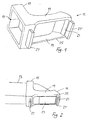
- Fig. 1
- eine perspektivische Darstellung eines Stativs,
- Fig. 2
- eine perspektivische Darstellung desselben Stativs, jedoch auf ein Objektiv aufgesetzt,
- Fig. 3
- ein Objektiv mit aufgesetztem Stativ in Aufnahmeposition im Backenzahnbereich,
- Fig. 4
- ein Objektiv mit aufgesetztem Stativ in Aufnahmeposition im Frontzahnbereich,
- Fig. 5
- ein Stativ mit lediglich einer vorderen Abstützung,
- Fig. 6
- ein Stativ mit einer keilförmigen hinteren Abstützung,
- Fig. 7
- ein Stativ mit aus plastischem, härtendem Material erstellter hinterer Abstützung,
- Fig. 8
- ein Stativ mit individuell bearbeiteten Abstützbalken.
- Fig. 1
- a perspective view of a tripod,
- Fig. 2
- a perspective view of the same tripod, but placed on a lens,
- Fig. 3
- a lens with a tripod in the receiving position in the molar area,
- Fig. 4
- a lens with a tripod in the receiving position in the anterior region,
- Fig. 5
- a tripod with only one front support,
- Fig. 6
- a tripod with a wedge-shaped rear support,
- Fig. 7
- a tripod with a rear support made of plastic, hardening material,
- Fig. 8
- a tripod with individually machined support beams.
Das in den Figuren 1 und 2 dargestellte Stativ 11
ist ein auf ein Objektivgehäuse 13 einer Vermessungskamera
aufsteckbares und vom Objektivgehäuse 13 wieder lösbares
Zubehörteil. Das längliche Objektivgehäuse 13 weist an seinem
vorderen Ende ein seitlich angeordnetes Objektivfenster 23
auf, durch welches hindurch die Videoaufnahmen gemacht
werden. Mit einem Ring 15 sitzt das aufgesteckte Stativ 11
hinter dem Objektivfenster 23 auf dem Objektivgehäuse 13 und
ist darauf verschiebbar. Der Ring 15 könnte auch an einer
Stelle einen Unterbruch 17 (in Fig. 1 gestrichelt
dargestellt) aufweisen. Mit dem Ring 15 oder der den
Unterbruch 17 aufweisenden Spange klemmt das Stativ 11 am
Objektivgehäuse 13 fest.The
Vom Halterteil, d.h. dem Ring 15 oder allenfalls der
Spange aus erstrecken sich zwei Arme 19 parallel gegen ein
diese Arme verbindendes Verbindungsteil 21, welches in einem
Abstand zum Ring 15 angeordnet ist. In aufgesetztem Zustand
begleiten die Arme 19 das Objektivgehäuse 13 beidseitig des
Objektivfensters 23. Der Ring 15, die Arme 19 und das
Verbindungsteil 21 bilden zusammen einen Rahmen 25, welcher
in auf das Objektiv 13 aufgesetztem Zustand das
Objektivfenster 23 umrahmen. Das Öffnungsmass des Rahmens 25
ist zwischen Ring 15 und Verbindungsteil 21 grösser als die
entsprechende Länge des Objektivfensters 23. Durch die
Klemmverbindung zwischen Ring 15 und Objektivgehäuse 13 ist
das Stativ 11 auf dem Objektiv 13 in Richtung der Arme 19
verschiebbar, in welcher Richtung das Öffnungsmass des
Rahmens 25 wesentlich länger ist als das Objektivfenster 23.
Ein zweckmässiger Verschiebungsspielraum liegt zwischen 5 und
10 mm.From the holder part, i.e. the
Am Ring 15 und am Verbindungsteil 21 ist je ein
Stützbalken 27,27' angeordnet. Ring 15, Arme 19,
Verbindungsteil 21 und Stützbalken 27,27' sind zusammen
einstückig aus einem Kunststoff hergestellt. Der Kunststoff
ist durch den Zahnarzt, Zahntechniker oder Laborant mit
seinen gewöhnlichen Werkzeugen bearbeitbar. Er ist auch
sterilisierbar und durch UV-Bestrahlung entkeimbar, ohne dass
dadurch die Materialeigenschaften rasch beeinträchtigt
würden.On the
Die Stützbalken 27,27' sind in Figur 1 und 2 in
einer Grundform dargestellt, welche verschiedene Abwandlungen
erlaubt. Diese Abwandlungen können als Fertigteile vorliegen
oder durch den Benutzer des Stativs 11 durch Abänderung der
Grundform individuell hergestellt werden. Die Grundform der
Stützbalken 27,27' ist etwa 3 bis 4 mm hoch, 12 bis 20 mm
lang und 2 bis 3 mm breit.The support beams 27, 27 'are shown in FIGS. 1 and 2 in
represented a basic form, which various modifications
allowed. These modifications can exist as finished parts
or by the user of the
Für eine Anwendung im Backenbereich, wie in Figur 3
dargestellt, werden die Stützbalken 27,27' unter Umständen
zweckmässigerweise bis auf etwa 1.5 mm abgetragen. Dies kann
auch lediglich in einem auf einem Zahn 29 aufliegenden
Teilbereich des Stützbalkens 27,27' geschehen. Dadurch liegen
auch die tiefstliegenden Bereiche des abzubildenden und zu
vermessenden Teils 31 - in Figur 3 ist dies ein Stift für
eine Krone - noch im Schärfebereich der Kamera.For use in the cheek area, as in Figure 3
shown, the support beams 27,27 'under certain circumstances
expediently removed to about 1.5 mm. This can
also only in one resting on a
Für eine Anwendung im Frontzahnbereich, wie es in
Figur 4 dargestellt ist, wird der Stützbalken 27' vorteilhaft
in seiner ganzen Höhe und Länge stehengelassen und auf dem
Zahnfleisch 33 oberhalb (bzw. bei unteren Frontzähnen
unterhalb) des zu vermessenden Zahns 35 abgestellt. Der
hintere Stützbalken 27 wird dabei nicht benötigt.For use in the anterior region, as in
Figure 4 is shown, the support beam 27 'is advantageous
left in its entire height and length and on the
In den Figuren 5 bis 8 sind verschiedene
Ausformungen der Abstützungen 27,27' dargestellt. In Figur 5
fehlt die hintere Abstützung 27. Dieses Stativ 11a ist daher
für den Frontzahnbereich geeignet. In Figur 6 ist am Stativ
11b die hintere Abstützung 27b keilförmig zugespitzt. Mit der
Keilspitze 37 kann im Zwischenraum zwischen zwei Zähnen
eingerastet werden, während der vordere, hier in der
Grundform vorliegende Stützbalken 27'b auf einen Zahn
aufgelegt werden kann.In Figures 5 to 8 are different
Formations of the
In Figur 7 ist ein wichtiges Ausführungsbeispiel 11c
des Stativs dargestellt. An der Stelle des hinteren
Stützbalkens 27 sind Retentionen 39 im Rahmen 15 angeordnet.
In diese Retentionen 39 kann eine thermoplastische oder
chemisch härtende, plastische Masse 41 gedrückt werden. Mit
dieser Masse 41 aufgebracht wird dann das Stativ 11c in
Aufnahmeposition gebracht. Dabei passt sich die Masse 41 der
Zahnoberfläche, auf die sie gepresst wird, an, und härtet
aus. Die ausgehärtete Masse 41 kann nun für eine zweite
Aufnahme vom gleichen Standort aus als exakte Führung und
Abstützung des Stativs dienen. Der Abdruck der Zahnoberfläche
kann ohne Mühe an die genau gleiche Stelle gesetzt werden.
Dabei lässt die Elastizität der ausgehärteten Masse 41 eine
leichte Korrektur der Position durchaus zu. Eine solche Masse
kann vorne oder hinten angebracht werden, oder auch vorne und
hinten. Als härtende, plastische Masse 41 können die für
Gebissabdrücke gebräuchlichen Materialien, wie Silikone,
Wachse, Kunststoffe verwendet werden.An important
In Figur 8 ist ein Stativ 11d dargestellt, mit an
die speziellen Gegebenheiten eines Patienten angepassten
Stützbalken 27,27'. Dieses Ausführungsbeispiel 11d soll
verdeutlichen, dass die Stützbalken auch in Querrichtung
individuell den Bedürfnissen angepasst werden können, und
dies während der Sitzung, im Laufe der Behandlung des
Patienten. Weiter zeigt die Figur 8, dass durch Verschieben
des Objektivs 13 im Stativ 11d der Bildauschnitt gewählt
werden kann. Das Objektiv 13 ist in Figur 8 - gegenüber zum
Objektiv in Figur 7 z.B. - zum Halterteil hin, d.h. zum Ring
15 hin verschoben. A
Da die heute gebräuchlichen Objektivgehäuse 13
leicht konisch nach vorne zusammenlaufend ausgestaltet sind,
muss das Halterteil 15 auf verschiedenen Querschnitten des
Objektivgehäuses 13 klemmen. Dazu ist auf der Innenseite des
Rings 15 etwa mittig auf jeder der vier Seiten des
rechteckigen Querschnitts eine leicht vorstehende
Friktionsfläche 43 ausgebildet. Dadurch besteht in den
Eckbereichen ein kleiner Zwischenraum zwischen dem Ring 15
und dem Objektiv 13. Bei grösserem Querschnitt des Objektivs
sind die Friktionsflächen 43 stärker auseinandergedrückt und
die Eckpartien des Rings 15 dem Objektivgehäuse 13 stärker
angenähert. Ein minimaler Zwischenraum zwischen Gehäuse 13
und Ring 15 ermöglicht diese leichte Verformung des Rings 15.
Je eine weitere Friktionsfläche 43' ist an den Armen 19
ausgebildet, um diese und damit die vordere Abstützung 27' zu
stabilisieren.Since the
Zusammenfassend kann gesagt werden, dass sich mit einem Stativ für eine zahnmedizinische Vermessungskamera die Aufnahmequalität verbessern lässt, während die Zeit für die Positionierung verkürzt und die Übereinstimmung von zwei Aufnahmen aus der gleichen Position erhöht werden kann. Das Stativ sitzt verschiebbar auf dem Objektivgehäuse und wird neben dem zu vermessenden Bereich z.B. auf den Zähnen abgestellt. Die Abstützungen sind mit zahnärztlichen Werkzeugen und Materialien auf die jeweiligen Gegebenheiten und Bedürfnisse anpassbar.In summary it can be said that with a tripod for a dental surveying camera Recording quality can improve while the time for the Positioning shortened and the match of two Recordings from the same position can be increased. The Tripod sits slidably on the lens housing and will in addition to the area to be measured e.g. on your teeth switched off. The supports are with dental Tools and materials to the respective circumstances and customizable needs.
Claims (11)
Priority Applications (2)
| Application Number | Priority Date | Filing Date | Title |
|---|---|---|---|
| EP98810936A EP0993802A1 (en) | 1998-09-18 | 1998-09-18 | Method for improving the quality of video-technical recording methods in dentistry, accessories for a dental camera, stand assembly |
| CA002280286A CA2280286A1 (en) | 1998-09-18 | 1999-08-13 | Process for improving the image quality of video imaging processes in the field of dentistry, accessories for a dental camera, support fixture |
Applications Claiming Priority (1)
| Application Number | Priority Date | Filing Date | Title |
|---|---|---|---|
| EP98810936A EP0993802A1 (en) | 1998-09-18 | 1998-09-18 | Method for improving the quality of video-technical recording methods in dentistry, accessories for a dental camera, stand assembly |
Publications (1)
| Publication Number | Publication Date |
|---|---|
| EP0993802A1 true EP0993802A1 (en) | 2000-04-19 |
Family
ID=8236334
Family Applications (1)
| Application Number | Title | Priority Date | Filing Date |
|---|---|---|---|
| EP98810936A Withdrawn EP0993802A1 (en) | 1998-09-18 | 1998-09-18 | Method for improving the quality of video-technical recording methods in dentistry, accessories for a dental camera, stand assembly |
Country Status (2)
| Country | Link |
|---|---|
| EP (1) | EP0993802A1 (en) |
| CA (1) | CA2280286A1 (en) |
Cited By (4)
| Publication number | Priority date | Publication date | Assignee | Title |
|---|---|---|---|---|
| WO2007018429A1 (en) * | 2005-08-10 | 2007-02-15 | Vetjens Marinus Johannes Petru | Oral measuring system |
| EP2389855A1 (en) * | 2007-03-16 | 2011-11-30 | Dürr Dental AG | Diagnosis camera and attachment for realising same |
| EP2592994A1 (en) * | 2010-07-15 | 2013-05-22 | Chris Leinweber | Intra-oral imager isolating device |
| FR3066095A1 (en) * | 2017-05-10 | 2018-11-16 | Jean Luc Berruet | DEVICE FOR AIDING THE HANDLING OF AN INTRA-ORAL CAMERA |
Citations (2)
| Publication number | Priority date | Publication date | Assignee | Title |
|---|---|---|---|---|
| US3812505A (en) * | 1972-11-06 | 1974-05-21 | Unitek Corp | Scanning camera |
| DE2505798A1 (en) * | 1975-02-12 | 1976-08-26 | Hans K Schneider | Video magnifier for dental treatment - using endoscope with video camera and monitor |
-
1998
- 1998-09-18 EP EP98810936A patent/EP0993802A1/en not_active Withdrawn
-
1999
- 1999-08-13 CA CA002280286A patent/CA2280286A1/en not_active Abandoned
Patent Citations (2)
| Publication number | Priority date | Publication date | Assignee | Title |
|---|---|---|---|---|
| US3812505A (en) * | 1972-11-06 | 1974-05-21 | Unitek Corp | Scanning camera |
| DE2505798A1 (en) * | 1975-02-12 | 1976-08-26 | Hans K Schneider | Video magnifier for dental treatment - using endoscope with video camera and monitor |
Cited By (5)
| Publication number | Priority date | Publication date | Assignee | Title |
|---|---|---|---|---|
| WO2007018429A1 (en) * | 2005-08-10 | 2007-02-15 | Vetjens Marinus Johannes Petru | Oral measuring system |
| EP2389855A1 (en) * | 2007-03-16 | 2011-11-30 | Dürr Dental AG | Diagnosis camera and attachment for realising same |
| EP2592994A1 (en) * | 2010-07-15 | 2013-05-22 | Chris Leinweber | Intra-oral imager isolating device |
| EP2592994A4 (en) * | 2010-07-15 | 2015-03-11 | Chris Leinweber | Intra-oral imager isolating device |
| FR3066095A1 (en) * | 2017-05-10 | 2018-11-16 | Jean Luc Berruet | DEVICE FOR AIDING THE HANDLING OF AN INTRA-ORAL CAMERA |
Also Published As
| Publication number | Publication date |
|---|---|
| CA2280286A1 (en) | 2000-03-18 |
Similar Documents
| Publication | Publication Date | Title |
|---|---|---|
| DE102004035091B4 (en) | Method for determining the position and orientation of the axis of a dental implant located directly in the patient's mouth and attachment therefor | |
| DE60030465T2 (en) | HEALING ELEMENTS FOR APPLICATION WHEN TAKING AN IMPRESSION | |
| DE3327122C2 (en) | ||
| EP2964136B1 (en) | Bite fork with recesses | |
| DE10154994A1 (en) | Process for transferring dental facial patient data to a dental articulator comprises using a recording plate which is placed in the mouth of a patient | |
| CH709747A1 (en) | Method and apparatus for three-dimensional measuring of tooth rows. | |
| DE102007012584A1 (en) | Method for controlling preparation of a prepared tooth by CAD method | |
| DE69918484T2 (en) | Device for scanning the centric relation of the mandible | |
| WO2020182702A1 (en) | Device and method for detecting jaw relation data | |
| DE102007034343B4 (en) | Bite fork and system having the bite fork | |
| EP0966927A2 (en) | Method and device for manufacturing medical articles, in particular dental prosthesis | |
| DE112010004857B4 (en) | Device and method for intraoral 3D data acquisition | |
| EP0993802A1 (en) | Method for improving the quality of video-technical recording methods in dentistry, accessories for a dental camera, stand assembly | |
| DE102017131134B4 (en) | Digital transfer sheet | |
| DE102017125671B4 (en) | Holding device for X-ray films | |
| EP0574868A2 (en) | Installation for guiding a dental instrument or a measuring device and method of preparing teeth and of producing restorations | |
| EP1304088A1 (en) | Method and apparatus of manufacturing dental prosthesis | |
| DE112011104785T5 (en) | Dental registration tool and method of interocclusal registration using the same | |
| DE102012018997B4 (en) | Method for positioning at least one dental arch model in an articulator, computer program and articulator | |
| DE112019006258T5 (en) | DENTAL MEASURING INSTRUMENT, MEASURING METHOD AND FASTENING INSTRUMENT | |
| DE202009003914U1 (en) | Device for determining the color of teeth | |
| DE102021118139A1 (en) | Method for animated pictorial representation of movements of the teeth of the lower jaw and position sensor holding device and system for carrying it out | |
| DE102007051742B4 (en) | Device for measuring the relevant for the tooth position reference points on the human face and its use | |
| DE102015206884B4 (en) | Universal bite fork | |
| DE202019101429U1 (en) | bitefork |
Legal Events
| Date | Code | Title | Description |
|---|---|---|---|
| PUAI | Public reference made under article 153(3) epc to a published international application that has entered the european phase |
Free format text: ORIGINAL CODE: 0009012 |
|
| AK | Designated contracting states |
Kind code of ref document: A1 Designated state(s): AT CH DE FI FR GB IT LI SE |
|
| AX | Request for extension of the european patent |
Free format text: AL;LT;LV;MK;RO;SI |
|
| 17P | Request for examination filed |
Effective date: 20000627 |
|
| AKX | Designation fees paid |
Free format text: AT CH DE FI FR GB IT LI SE |
|
| RAP1 | Party data changed (applicant data changed or rights of an application transferred) |
Owner name: METTLER, MAX, DR. MED. DENT. |
|
| RIN1 | Information on inventor provided before grant (corrected) |
Inventor name: METTLER, MAX, DR. MED. DENT. |
|
| RAP1 | Party data changed (applicant data changed or rights of an application transferred) |
Owner name: C-STAT GMBH |
|
| RIN1 | Information on inventor provided before grant (corrected) |
Inventor name: C-STAT GMBH |
|
| 17Q | First examination report despatched |
Effective date: 20030707 |
|
| STAA | Information on the status of an ep patent application or granted ep patent |
Free format text: STATUS: THE APPLICATION IS DEEMED TO BE WITHDRAWN |
|
| 18D | Application deemed to be withdrawn |
Effective date: 20031118 |