EP0993144B1 - Appareil de relais de paquets et méthode et circuit correspondants - Google Patents
Appareil de relais de paquets et méthode et circuit correspondants Download PDFInfo
- Publication number
- EP0993144B1 EP0993144B1 EP19990117151 EP99117151A EP0993144B1 EP 0993144 B1 EP0993144 B1 EP 0993144B1 EP 19990117151 EP19990117151 EP 19990117151 EP 99117151 A EP99117151 A EP 99117151A EP 0993144 B1 EP0993144 B1 EP 0993144B1
- Authority
- EP
- European Patent Office
- Prior art keywords
- address
- node
- route
- search
- branch
- Prior art date
- Legal status (The legal status is an assumption and is not a legal conclusion. Google has not performed a legal analysis and makes no representation as to the accuracy of the status listed.)
- Expired - Lifetime
Links
Images


Classifications
-
- H—ELECTRICITY
- H04—ELECTRIC COMMUNICATION TECHNIQUE
- H04L—TRANSMISSION OF DIGITAL INFORMATION, e.g. TELEGRAPHIC COMMUNICATION
- H04L45/00—Routing or path finding of packets in data switching networks
- H04L45/74—Address processing for routing
- H04L45/742—Route cache; Operation thereof
-
- H—ELECTRICITY
- H04—ELECTRIC COMMUNICATION TECHNIQUE
- H04L—TRANSMISSION OF DIGITAL INFORMATION, e.g. TELEGRAPHIC COMMUNICATION
- H04L12/00—Data switching networks
- H04L12/02—Details
- H04L12/16—Arrangements for providing special services to substations
- H04L12/18—Arrangements for providing special services to substations for broadcast or conference, e.g. multicast
-
- H—ELECTRICITY
- H04—ELECTRIC COMMUNICATION TECHNIQUE
- H04L—TRANSMISSION OF DIGITAL INFORMATION, e.g. TELEGRAPHIC COMMUNICATION
- H04L12/00—Data switching networks
- H04L12/28—Data switching networks characterised by path configuration, e.g. LAN [Local Area Networks] or WAN [Wide Area Networks]
- H04L12/46—Interconnection of networks
-
- H—ELECTRICITY
- H04—ELECTRIC COMMUNICATION TECHNIQUE
- H04L—TRANSMISSION OF DIGITAL INFORMATION, e.g. TELEGRAPHIC COMMUNICATION
- H04L45/00—Routing or path finding of packets in data switching networks
-
- H—ELECTRICITY
- H04—ELECTRIC COMMUNICATION TECHNIQUE
- H04L—TRANSMISSION OF DIGITAL INFORMATION, e.g. TELEGRAPHIC COMMUNICATION
- H04L45/00—Routing or path finding of packets in data switching networks
- H04L45/16—Multipoint routing
Definitions
- the present invention relates to a packet relaying apparatus for relaying a packet in a plurality of interconnected networks, and more particularly to a method of searching a next node to which a multicast packet is transmitted.
- IP network packet communication network by Internet Protocol: hereinafter called an IP network
- IP network not only conventional data communication applications, but also real time applications such as Internet phones and Internet broadcasting are used to provide a voice communication function and a broadcasting function.
- IP multicast techniques for the IP network are expected as effective techniques for the distribution of multimedia data such as moving images, voices and contents on the Internet.
- IP network Support and high speed operation of a packet relaying apparatus (router) constituting the IP network are the main issue of IP multicast techniques.
- a router searches from a routing table, route information corresponding to a receiver IP address contained in a header of a received packet, and transmits the received packet to the next router.
- the route information includes an IP address of the next router or a terminal and a transmission port number of the router.
- the routing table stores a plurality of information groups for each receiver IP address, the information groups including a corresponding sub-network address, a sub-net mask length, and the route information.
- This information group is called an entry.
- the sub-network is a partial collection of terminals such as a receiver corporate network.
- the sub-network address is an address group which is obtained by coupling IP addresses of the partial collection as address information.
- the sub-net mask length is a value indicating how many upper bits of an IP address are an identifier of the sub-network.
- the router compares the sub-network address in the entry with the effective upper bits, masked by the sub-net mask length in the entry, of a receiver IP address contained in a received packet.
- the router uses the route information in the coincident entry as the search result. Since the entry is configured in the unit of sub-network, the number of entries in the routing table can be reduced considerably and the search process is made efficient. If it is judged that a plurality of entries are coincident, the route information in the entry having the longest sub-net mask length is used as the search result. In the following, this search is called a longest coincidence search.
- each entry of the routing table includes a sender sub-net address, an address mask, a multicast group address and route information.
- the multicast group address is an identifier assigned to a plurality of receiver collections (hereinafter called a multicast group) to which the sender transmits the packet.
- a router searches the routing table by using as a search key a multicast group address in the sender IP address and receiver IP addresses in the header field of a received packet.
- the route information of an entry with a search coincidence is constituted of a plurality of transmission port numbers. In accordance with the transmission port numbers, the router copies the received packet and transmits it to the specific multicast group.
- a high speed operation to be attained through a router load dispersion method is described, for example, in JP-A-6-197111 laid-open on July 15, 1994 (hereinafter called "first related art").
- This first related art aims to realize a router capable of a high speed relay operation through a load dispersion method.
- a plurality of packet relay modules are connected to a bus, and each packet relay module provides a packet relay function by referring to routing table information supplied from a management unit connected to the bus. If the number of packet relay modules is increased, the performance can be improved.
- the packet relay module of the first related art includes: a routing processing unit which derives the header of a received packet and performs a search process for a packet receiver; and a transfer processing unit which stores the received packet in a memory and transfers the received packet to another packet relay module designated by the search result. Since the different processing units take partial charge of the relay function, the packet relay process can be speeded up. However, the first related art does not describe a high speed multicast packet relay process.
- a search (hereinafter called a multicast route search) of a receiver of a multicast packet to be performed by a router is described, for example, in " TCP/IP Illustrated, Volume 2 The Implementation", 1995, pp. 416-421 (Addison-Wesley Publishing Company) (hereinafter called a second related art).
- the routing table search is speeded up by using a hash search method. If the routing table information is directly searched, the time taken to execute a search process becomes considerably long as the number of receiver IP addresses increases and the number of entries of the table increases.
- a sender ID address in a received packet is used as a key for calculating a hash value, and a routing table group is provided which stores grouped entries of the receiver IP addresses having the same hash value.
- the route search processing unit in the router calculates the hash value from the sender IP address in the received packet and the routing table corresponding to the hash value is searched. Since the search range of the routing table is limited in accordance with the hash value, the route search can be speeded up.
- a Radish algorithm is known as one of route searching methods.
- the Radish algorithm is described, for example, in "A technical memo of WIDE project, Kazukio Yamamoto, Akira Kato and Akira Watanabe, Radish-A Simple Table Structure for CIDR (hereinafter called a third related art).
- a routing table of the Radish type uses entries of a two-branch tree structure to speed up the route search. More specifically, each entry is allocated to each of a plurality of apexes (nodes) interconnected by right and left pointers of each node constituting a two-branch tree structure wherein the root (two-branch tree root) corresponds to the highest bit of an IP address format.
- the receiver IP address in a received packet is checked one bit after another starting from the highest bit, and one of right and left pointers is selected in accordance with the checked bit value (0 or 1) to move to the next node. With this search, the node assigned the target entry can be reached.
- the two-branch tree is traced by checking the receiver IP address one bit after another. Therefore, even if the number of entries of the routing table becomes large, the search can be completed by performing a check (tracing the two-branch tree) as many as the number of bits of the receiver IP address at the maximum.
- the network address comparator circuit is used for checking at the same time one or a plurality of consecutive bits to be checked at a branch omitted as unnecessary from the two-branch tree of the Radish type, by comparing a network address at the node and the receiver IP address in a received packet masked by the node. If the comparison result indicates a coincidence, it means that a correct node was reached, whereas if incoincidence, it means that an incorrect node was reached.
- a next node selection process and the network address comparison process are executed in parallel to speed up the route search process.
- the two-branch tree is structured by a method different from the Radish type of the third related art.
- the longest coincidence search for the two-branch tree is performed at high speed. More specifically, with the two-branch tree searching method of the seventh related art, the receiver IP address in a received packet which is sub-net masked by the node is compared with the sub-network address of the node.
- the route information of this node is used as the search result to terminate the route search, where as if incoincidence, the masked receiver address and the sub-network address of the node are assumed to be an integer not smaller than 0, and both the addresses are compared to trace one of right and left branches of the two-branch tree in accordance with the comparison result.
- the search is performed in the order of longer mask length so that the longest coincidence search can be realized.
- the mask length is defined as a length of lower bits different from the sub-network address portion of the IP address.
- the longest coincidence search method is called a best match method. This best match method adopts the shortest mask length as the search result.
- US-A-5 796 944 discloses a communications internet working device with search circuits for searching a network address table for source and destination addresses of received data frames.
- the present IP multicast communication is only used limitatively in the multicast network virtually configured on the Internet.
- the scale of the multicast network is not so large and the search process and transfer process of multicast communication do not degrade the transfer performance of a rooter as yet.
- applications using the multicast function are prevailed on the Internet in the future, the number of entries of the multicast routing table in a rooter becomes large. Therefore, it is desired to realize a high speed operation of a search process for the routing table even under the conditions of a large number of entries.
- the multicast route searching method of the hash type is described in the second related art.
- the method of calculating a hash value is always the same irrespective of the number of entries. It is not possible to flexibly increase the number of routing table groups in accordance with an increase in the number of entries. Therefore, if the number of entries increases, the grouped routing table itself becomes large and an average search time becomes long.
- the unicast route searching method using the Radish algorithm has a merit that even if the number of entries in the routing table increases, the search process time does not become long.
- the sixth related art describes the maximum search time shortened by 1/N by changing the two-branch tree structure to N-th power-of-2-branch trees, it does not describe the multicast route search.
- the two-branch tree structure of the third related art is determined uniquely by the entries to be registered and its maximum search time is determined by the number of bits of a search key.
- the two-branch tree structure of the seventh related art may have in some cases a tree having nodes coupled long in one direction and a long average search time, depending upon a tree configuring method. In order to avoid such a tree having a long train of nodes, it is necessary to use an algorithm which makes the two-branch tree broaden uniformly.
- the seventh related art does not describe such an algorithm.
- the seventh related art describes that when the two-branch tree of the seventh related area is configured, if entries having the longer mask length are disposed at the upper level of the two-branch tree, the search is performed in the order of longer mask length so that the longest coincidence search can be realized.
- the details of coupling nodes having different mask length are not given.
- the seventh related art traces the right and left branches of the two-branch tree in accordance with the comparison result of addresses. Therefore, a p-th power-of-2-branch system cannot be realized.
- the sender ID address and receiver multicast group address are coupled to form and define one route address.
- a multicast routing table of a two-branch tree is configured. Each bit starting from an upper bit of the route address coupling the sender ID address and receiver multicast group address in a received multicast packet is checked, and in accordance with a value of the checked bit, a search tree of a two-branch tree structure is searched.
- the route address is defined by coupling the receiver multicast group address and sender ID address in this order, and in accordance with a bit pattern of this route address, the multicast routing table of the two-branch tree is configured.
- the number of branches of each node constituting a search tree of the two-branch tree is increased by a power of 2, from a two-branch tree node to a four-branch tree node, an eight-branch tree node, or generally a p-th power-of-2-branch tree to configure a multicast routing table of the p-th power-of-2-branch tree structure. Not one bit per one node, but consecutive two bits, three bits, or generally p bits of the route address coupling the receiver multicast group address and sender IP address in a received multicast packet in this order are checked at the same time. In accordance with the values of the consecutive bits, the multicast routing table of the p-th power-of-2-branch is searched.
- the multicast group address itself is not used but the multicast group ID of the lower 28 bits of the multicast group address and the sender IP address coupled in this order are used.
- the multicast routing table is configured as a two-branch tree or a p-th power-of-2-branch tree.
- a collection of one two-branch tree node and two-branch tree nodes of (p-1) stages, totalling in ((a p-th power of 2) - 1) nodes just under the one upper node, is used as one p-th power-of-2-branch tree node.
- the (p-1)-th power of 2) two-branch nodes at the lowest stage collected are embedded with the entry data assigned to the nodes at the higher stages to form one p-th power-of-2-branch tree node by using ((p-1)-th power of 2) two-branch nodes.
- one element of node data common to a plurality of two-branch tree is stored.
- the transmission port information is separated from the node data of the search tree and stored in another area of a memory.
- the data amount of the two-branch tree node assigned an entry becomes equal to the data amount of the two-branch tree node not assigned an entry, to thereby configure a p-th power-of-2-branch tree nodes by collecting such two-branch tree nodes.
- the mask length of each p-th power-of-2-branch tree node is not stored but the mask length of another node just under the p-th power-of-2-branch tree node is stored.
- all the data of the node is not read from storage means storing the search tree data to be used for a route search process, but only the necessary portion of the node data is read by using the mask length stored in the node data which was read immediately before.
- a flag indicating whether an entry is assigned to the node is provided at the start of the node data. This flag is first read, and if the entry is not assigned, the route information of this node is not read.
- (m-power of 2) p-th power-of-2-branch tree nodes corresponding in number to the upper m bits of the route address are developed on the storage means at predetermined positions.
- Each of the developed nodes is being set in one-to-one correspondence with each value which the 0-th bit to (m-1)-th bit of the route address can take.
- one of the developed nodes is selected.
- a circuit for searching a multicast routing table of a p-th power-of-2-branch tree structure in which: a route address is formed by coupling a receiver address and a sender address in this order; storing means is provided for storing by developing (m-th power of 2) p-th power-of-2-branch tree nodes of a p-th power-of-2-branch tree structure corresponding to the upper m bits of the route address, at predetermined positions; one of the developed nodes in the storage means at predetermined positions is selected in accordance with the 0-th bit to (m-1)-th bit of the route address coupling the receiver address and sender address; and every p bits of the route address after the m-th bit of the route address are checked.
- a network shown in Fig. 2 is constituted of: terminals (T11, T12, T21, T22, T31, T32, T41, T422, T51, T52) to and from which a packet is transferred; sub-networks (SN1 to SN5) for interconnecting the terminals; and routers (R1 to R3) for interconnecting the sub-networks.
- the router R1 has ports P11, P12 and P13
- the router R2 has ports P21, P22, P23 and P24
- the router R3 has ports P31, P32, P34 and P35.
- Each terminal is assigned an address as an identifier.
- each terminal of an IP network is assigned an IP address of 32 bits.
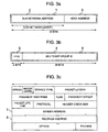
- An IP address will be described with reference to Fig. 3a .
- An IP address 1 shown in Fig. 3a has a sub-network address 2 and a host address 3.
- the sub-network address is an identifier of the sub-network
- the host address is an identifier of a terminal in the sub-network.
- the number of bits of the sub-network is indicated by a sub-net mask length.
- the sub-network address can be obtained from an IP address by calculating the logical products of the IP address bits and the effective upper bits masked (sub-net masked) by the sub-net mask length.
- a packet relaying operation in unicast communication of transmitting a packet from one terminal to another terminal will be described with reference to Fig. 2 . It is assumed for example that a unicast packet is transmitted from the terminal T11 to the terminal T22.
- a header format of a packet to be transmitted is shown in Fig. 3c .
- a sender IP address filed 7 shown in Fig. 3c an IP address of the sender terminal T11 is stored, and in a receiver IP address field 8, an IP address of the receiver terminal T22 is stored.
- the router R1 When the router R1 receives the unicast packet from the terminal T11, the router R1 checks the receiver IP address field in the packet header so that it can recognize that the receiver terminal T22 is on the sub-network SN2 and the sub-network SN2 is connected to the router R2. The router R1 then decides the IP address (called a next hop IP address) of the router R2 and the port P12 and transmits the packet.
- the router R2 receives the unicast packet from the router R1
- the router R2 checks the receiver IP address field in the packet header so that it can recognize that the receiver terminal T22 is on the sub-network SN2 and the sub-network SN2 is directly connected to the router R2.
- the router R2 decides the next hop IP address (in this example, IP address of the terminal T22) and the port P22 and transmits the packet.
- the routing unit 13-i searches a unicast routing table by using as a key the receiver IP address in the header of the packet. With this search, the next hop IP address and the number (transmission port number) of the output port 12-i are decided.
- the packet added with the next hop IP address and transmission port number is supplied to the switch 14.
- the switch 14 switches the packet to the communication control unit 15-i having the output port 12-i corresponding to the transmission port number.
- the communication control unit 15-i received the switched packet decides a MAC (media access control) address of the data link layer corresponding to the next hop IP address added to the packet, in accordance with a correspondence table, adds the MAC address to the packet as a receiver MAC address, and sends the packet to the output port 12-i corresponding to the transmission port number.
- MAC media access control
- the unicast routing table is formed by the managing unit 16 which exchanges connection information with other routers and distributes the table to each routing unit 13-i.
- the managing unit also exchanges information on the data link layer with other routers and terminals to form the correspondence table between each next hop IP address and each MAC address of a router and terminal having the next hop IP address, and distributes the table to each communication control unit 15-i.
- a packet relaying operation in multicast communication of transmitting a packet from one terminal to a plurality of terminals will be described with reference to Fig. 2 .
- the multicast group is identified by an IP address (multicast group address) of a class D.
- the structure of an IP address of the class D is shown in Fig. 3b .
- An IP address 4 of the class D is constituted of upper 4 bits "1110" representative of the class D indicated at 5 and a multicast group ID (hereinafter abbreviated as GID) of 28 bits indicated at 6.
- GID multicast group ID
- the multicast group identified by the multicast group address can cover a plurality of sub-networks.
- the member structure of terminals belonging to the group is dynamic and each terminal can participate in or secedes from the multicast group.
- the IP address of the sender terminal T11 is stored, and in the receiver IP address field (8 in Fig. 3c ), a receiver multicast group address is stored as different from the unicast packet.
- the router R1 received the multicast packet from the terminal T11 checks two fields, the sender IP address field and receiver IP address field in the packet header, so that it can recognize that the sender terminal T11 of the multicast packet is on the sub-network SN1.
- the router R1 decides the transmission ports P12 and P13 and outputs a copy of the packet from these ports, in order to transmit the packet from the sub-network SN1 to all terminals belonging to the receiver multicast address.
- the router R2 received the multicast packet from the router R1 performs a check similar to the router R1 so that it can recognize that the sender terminal T11 of the multicast packet is on the sub-network SN1. and the router R2 decides the transmission ports P22 and P23 and outputs a copy of the packet from these ports, in order to transmit the packet from the sub-networks SN2 and SN3 having the terminal belonging to the receiver multicast address.
- the router R3 decides the ports P34 and P35 and outputs a copy of the packet received via the router R1 from these ports.
- the routing unit 13-i searches a multicast routing table by using as a key the sender IP address and receiver IP address (receiver multicast address) in the header of the packet. With this search, the number (transmission port number) or numbers of one or a plurality of output ports 12-i are decided, and a copy of the received packet added with each transmission port number is sent to the switch 14. The switch 14 switches the packet to the communication control unit 15-i having the output port 12-i corresponding to each transmission port number.
- the communication control unit 15-i received the switched packet generates a multicast MAC address of the data link layer by using the receiver multicast address in the header of the multicast packet, adds the MAC address to the packet as the receiver MAC address, and sends the packet to the output port 12-i corresponding to each transmission port number, as different from the case of the unicast packet.
- the multicast routing table is formed by the managing unit 16 which exchanges connection information with other routers and distribute the table to each routing unit 13-i.
- Reference numeral 500 represents a switch corresponding to the switch 14 shown in Fig. 4 .
- a management unit 601 is connected to the switch 505.
- the managing unit 601 has a function of managing the router and collecting and distributing routing information.
- the managing unit 601 corresponds to the managing unit 16 shown in Fig. 4 .
- the switch 505 can be connected to a plurality of packet processing units 600 having a function of relaying a packet at high speed.
- the packet processing unit 600 corresponds to the routing unit 13-i shown in Fig. 4 .
- the managing unit 601 distributes the routing table to each packet processing unit 600 which performs a packet relaying process in accordance with the routing table to thereby realize the functions of the router.
- Each packet processing unit 600 is connected to communication control units 501, 602 and 603 (corresponding to the communication control unit 15-i in Fig. 4 ) each having communication ports for network interconnection.
- the communication control unit can be connected to various types of networks.
- the communication control unit can be connected to one or a plurality of networks depending upon the communication speed of each network, by providing one port for high speed communication (e.g. 500 in Fig. 1 ) and a plurality of ports for low speed communication (e.g., 604 and 605 in Fig. 1 ).
- the packet processing unit 600 includes: a transfer processing unit 504 for executing a packet transfer process; a memory 503 with a packet buffer for storing a packet; a route search processing unit 400 for searching a route by using header information in the packet stored in the memory 503; and a control circuit 502 for controlling the transfer processing unit 504 and communication control unit 501.
- the route search processing unit 400 is constituted of a memory 300 for storing a routing table and a route search processing circuit 200 for searching the routing table and outputting the search result to the transfer processing unit 504.
- the managing unit 601 distributes each multicast routing table to all packet processing units 600 connected to the switch 505 and each packet processing unit stores the routing table in the memory 300.
- the communication control unit 501 stores a multicast packet received from the network 500 in the memory 503.
- the transfer processing unit 504 derives the packet header information from the packet data stored in the memory 503, and transfers it to the route search processing unit 400.
- the route search processing circuit 200 search the multicast routing table stored in the memory 300, by using the sender address and receiver multicast group address in the header of the received packet, and transfers N (N is an integer of 1 or larger) transmission port numbers as the search result to the transfer processing unit 504.
- the transfer processing unit 504 Upon reception of the search result, the transfer processing unit 504 rewrites the packet header of the packet stored in the memory 503, adds one of the N transmission port numbers to the packet, and transfers the packet to the switch 505. This operation is repeated N times by the transfer processing unit 504 to complete the transfer process for one received packet. If the transmission port number corresponds to the port number of the communication control unit connected to its own packet processing units, the packet is transmitted to the communication control unit connected to its own packet processing unit.
- the switch 505 switches the packet transferred from the transfer processing unit 504 to each packet processing unit in accordance with the transmission port number added to the packet.
- the packet processing unit 600 received the switched packet transfers the packet to the communication control unit (501, 602, 603).
- the communication control unit generates the multicast MAC address from the receiver multicast address in the header of the packet, adds the receiver MAC address to the packet, and transmits the packet to each network.
- the invention relates to a high speed operation of the route search processing unit 400.
- a first method to be executed by the route search processing unit 400 will be described.
- the multicast routing table is structured as a two-branch tree and this two-branch tree structure is used for searching a route (hereinafter called a two-branch tree searching method).
- a second method which is an improved version of the first method allowing a higher operation speed will be described.
- the multicast routing table is structured as a p-th power-of-2-branch tree and this p-th power-of-2-branch tree structure is used for searching a route (hereinafter called a p-th power-of-2-branch tree searching method).
- the multicast routing table is searched by using as a search key the sender IP address and receiver multicast group address in the header of a received packet. Namely, with a combination of these two pieces of information, a route of a multicast packet from the sender to the receiver can be identified.
- a multicast routing table can be configured by using at its entry a pair of this route address and route information. In this case, the multicast routing table can be searched by using the route address as a search key.
- the multicast group address is assigned one-to-one correspondence with the multicast group. Therefore, when the routing table is searched, a coincidence with the multicast group address in each entry is checked.
- the sender IP address uses as the search result the entry route information having the sender sub-network address in the entry coincident with the effective upper bits in the entry masked by a sub-network mask length. In this case, similar to the unicast route search, it is necessary to perform a longest coincidence search.
- the order of coupling the sender IP address and multicast group address is set so that the first is the multicast group address and the second is the sender IP address.
- This couple is defined as the route address
- the multicast routing table is structured as the two-branch tree structure in accordance with the bit pattern of the route address.
- the longest coincidence search can be performed for the route address.
- the coincidence check can be performed for the multicast group address, and the longest coincidence search can be performed for the sender IP address.
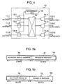
- Figs. 5a and 5b show route addresses to be used when a multicast routing table of the two-branch tree structure is searched. These route addresses are also applied to the p-th power-of-2-branch tree searching method to be described later.
- a route address shown in Fig. 5a is a couple of a multicast group address 30 and a sender IP address 31 and has 64 bits.
- a route address 33 shown in Fig. 5b is a couple of a multicast group ID 34 removing the upper four bits "1110" representative of the class D of the IP address from the multicast group address 30 and a sender IP address 31, and has 60 bits.
- the tree structure becomes shallower and the maximum number of loads to be traced during the search becomes smaller, the smaller the number of bits of a value (in this example, search address) constituting a tree structure. Therefore, in the following description, the route address 33 shown in Fig. 5b having the smaller number of bits is used.
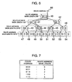
- Fig. 6 shows an example of the two-branch tree structure.
- each node has a route address "aaa”, a route address mask length n, and pointers to two lower level nodes.
- the route address mask length indicates the number of effective upper bits of the route address of the node, and also indicates a check bit position of the route address in a packet received at the node.
- a pair of the route address and route address mask length is represented by a notation "aaa : n".
- a masked route address is represented by this notation.
- Nodes of the tree are called a node with a route address length of 0 bit, a node with a route address length of 1 bit, a node with a route address length of 2 bits, a node with a route address length of 3 bits, in the order from the top to the bottom.
- the 0-th bit of the route address indicated by the route address mask length is checked.
- the route is moved to the node (41, 42) with the route address length of 1 bit in accordance with the right/left pointer which is selected depending upon whether the value of the 0th bit is 0 or 1.
- the route is moved to the node (43, 44, 45, 46) with the route address length of 2 bits in accordance with the right/left pointer which is selected depending upon whether the value of the first bit of the route address is 0 or 1.
- the route is moved to the node (47, 48, 49, 50, 51, 52, 53, 54) with the route address length of 3 bits in accordance with the right/left pointer which is selected depending upon whether the value of the second bit of the route address is 0 or 1.
- a route address is checked starting from the node 40 with the route address mask length of 0 bit, by tracing the tree in accordance with each pointer which is selected whether the value of each bit is 0 or 1.
- the node having the route address length of 0 bit is traced even if the route address has any value.
- the node (41, 42) with the route address mask length of 1 bit is traced if the bits of a route address are "0xx" or "1xx” as viewed sequentially from the left to right.
- the node (43, 44, 45, 46) with the route address mask length of 2 bits is traced if the bits of a route address are "00x", "01x", "10x”, or "11x” as viewed sequentially from the left to right.
- the node (47, 48, 49, 50, 51, 52, 53, 54) with the route address mask length of 3 bits is traced if the bits of a route address are "000", "001", “010", “011”, “100”, “101", “110” or “111” as viewed sequentially from the left to right.
- x means that the bit value may take either 0 or 1.
- the node 40 with the route address mask length of 0 bit is traced if the route address has a masked route address "000 : 0".
- the node (41, 42) with the route address mask length of 1 bit is traced if the route address has a masked route address "000 : 1" or "100 " 1”.
- the node (43, 44, 45, 46) with the route address mask length of 2 bits is traced if the route address has a masked route address "000 : 2", “010 : 2", "100 : 2" or "110 : 2".
- the node (47, 48, 49, 50, 51, 52, 53, 54) with the route address mask length of 3 bits is traced if the route address has a masked route address "000 : 3", "001 : 3",..., or "111 : 3".
- each node of the tree is one-to-one correspondence with each of all the masked route address having different route addresses and route address mask lengths.
- entries corresponding to the nodes 40, 48, 44, 42 and 53 are allocated to a multicast routing table shown in Fig. 7 . More specifically, as will be later described with reference to Figs. 12a and 12b , a flag indicating whether an entry is being assigned is provided in the data structure of each node. The value of the flag is set to "1" if an entry is assigned to the node, and transmission port information or a pointer to the transmission port information is stored in the node data structure.
- a node affixed with * means that the node is being assigned an entry.
- the route address in a received packet is "011" (at 60 in Fig. 6 ), through a masked route address search following pointers of this tree to be selected depending upon whether each bit is 00 or 1, it is confirmed that the nodes 40 and 44 with "*" are coincident. If a plurality of entries of the routing table are coincident, the longest coincidence search is performed for the sender IP address. Therefore, the node having the longest route address mask length defined as above, i.e., the node 44 nearest to the tree end is selected from the coincident nodes 40 and 44 with "*", and the route information in the entry assigned to this node 44 is used as the search result of the routing table. In the example of the routing table shown in Fig. 7 , the route information in the entry is omitted.
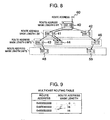
- the search result does not affected even if the nodes 47, 49, 50, 51, 52, 54, and 45 which are not affixed with "*" and do not constitute an intermediate route to the node with "*", are removed from the tree. If the node at the tree end is not affixed with "*", the search can be completed without tracing the node to the tree end. If the nodes which are not affixed with "*" and do not constitute an intermediate route to the node with "*", are removed from the tree, a tree shown in Fig. 8 is obtained.
- a two-branch tree corresponding to a routing table shown in Fig. 9 is structured by using the above-described method.
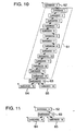
- a long string 61 of nodes without any branch and "*" shown in Fig. 10 is therefore obtained.
- the route information in the entry is omitted from the routing table shown in Fig. 9 .
- a notation "0xNNNNNNNN” means "NNNNNNNN” is a hexadecimal number.
- the string 61 of nodes without any branch and "*" is removed and the node 63 just under the removed node train 61 is connected to the branch direction (right in Fig. 10 ) of the node 62 just above the removed node train 61.
- the resultant tree is as shown in Fig. 11 . Removing the intermediate node train is hereinafter called a tree degeneration.
- the coincidence check indicates a coincidence, it means that the correct node is reached, i.e., that this node is reached even if each bit is checked by using a tree not degenerated. If the coincidence check does not indicate a coincidence, it means an incorrect node is reached, i.e., that there is no receiver node in a tree not degenerated.
- the 0-th bit is already checked and a branch is selected to have the same 0-th bit. Therefore, a coincidence is always retained. Generally, if it is checked at each node whether the node is a correct one or not, it can be guaranteed that the 0-th bit to the bit corresponding to the route address mask length of the route address in a received packet are coincident with those of the route address at the node. Therefore, when the next node is reached, irrespective of whether a coincidence check was performed to which bits, a coincidence check may be performed whether the 0-th bit to the bit corresponding to the route address mask length of the route address in a received packet are coincident with those of the route address at the node.
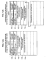
- a next node mask length 0, 1 in words 110 and 110 is not the route address mask length of this node, but the route address mask length just under this node. Not its own route address mask length but the route address mask length just under the node is set in order to speed up the search. This will be later detailed with reference to Figs. 20a and 20b .
- a flag 0, 1 field sets a flag (hereinafter called an entry flag) indicating whether this node has an entry, i.e., in the examples of the trees shown in Figs.
- a next node pointer 0, 1 in the words 110 and 111 is a pointer to the next node which is selected depending upon whether the value of the route address at a bit position indicated by the route address mask length of this node is 0 or 1.
- a route address in words 112 and 113 is a route address of this node.
- the word 112 is set with upper 28 bits of the route address at this node
- the word 113 is set with lower 32 bits of the route address sat this node.
- transmission port information 114 is stored in the data structure of the two-branch node.
- the transmission port information 114 is separated from the node structure of the two-branch tree node structure, and a pointer 115 to the separated transmission port information is stored.
- the transmission port information indicates one or a plurality of transmission port numbers from which ports a received multicast packet is transferred.
- the transmission port information requires several words if the number of ports of the router is large. Therefore, if the transmission port information 114 is stored in the two-branch tree node structure as shown in Fig.
- the size of the node structure becomes very different between the two-branch tree node assigned an entry and the two-branch tree node not assigned an entry. If the sizes of the nodes are different, the number of bits necessary to the next node pointer in the node increases and a process of calculating the real address of a memory from the pointer becomes complicated. The hardware structure in particular becomes complicated.
- the size of the node becomes constant irrespective of whether an entry is assigned or not assigned, and the hardware structure can be simplified.
- the maximum search time is proportional to the number of bits of a search key. It is desired to considerably shorten the maximum search time to speed up the search operation.
- one node has branches raised to the p-th power of 2 and every p bits are checked at the same time to shorten the search time by 1/p as compared to the related art.
- a node having branches raised to the p-th power of 2 is hereinafter called a p-th power-of-2-branch tree node.
- a p-th power-of-2-branch tree node is formed by modifying a tree constituted of two-branch tree nodes described with the two-branch tree searching method.
- one two-branch tree node having a route address mask length n and lower level two-branch tree nodes having the route address mask length of (n + 1) bits to (n + p - 1) bits are used as one p-th power-of-2-branch tree node.
- This p-th power-of-2-branch tree node inherits the mask length n of the two-branch tree node at the top of the tree and n is defined as the mask length of the p-th power-of-2-branch tree node.
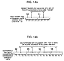
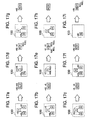
- a method of modifying a two-branch tree to an eight-branch tree will be described with reference to Figs. 13a to 13c .
- a two-branch tree node to be used as an eight-branch tree node is selected by three different partition methods.
- One method ( Fig. 13a ) uses two-branch tree nodes having mask lengths of 0 to 2, 3 to 5,..., 57 to 59, and 60 bits 6 to 58, 59, respectively as one eight-branch tree node
- another method ( Fig. 13b ) uses two-branch tree nodes having mask lengths of 1 to 3, 4 to 6,..., 55 to 57, and 58 to 60 bits, respectively as one eight-branch tree node
- the last method ( Fig. 13a ) uses two-branch tree nodes having mask lengths of 1 to 3, 4 to 6,..., 55 to 57, and 58 to 60 bits, respectively as one eight-branch tree node.
- 13c uses two-branch tree nodes having mask lengths of 2 to 4, 5 to 7,..., 56 to 58, and 59 to 60 bits, respectively as one eight-branch tree node. Any one of these partition methods may be used. In order to facilitate addition and deletion of an entry of the tree, one of the three bit position partition methods is used.
- the tree does not start from the mask length of 0 bits. Therefore, the 0-th bit check is required to be performed separately. For this check, a method (hereinafter called third method) of developing nodes having the mask bit length of m upon a memory at predetermined positions.
- third method a method of developing nodes having the mask bit length of m upon a memory at predetermined positions.
- nodes having the mask length of m are developed in advance in a memory at predetermined positions, and when the route search starts, one of the developed nodes is selected and read from the memory, in accordance with the value of the upper m bits of the route address in a received packet.
- a search time for the upper m bits can be omitted.
- the first 0-th bit is checked by disposing the eight-branch tree nodes 90 and 91 having the mask length of 1 bit on the memory at predetermined positions and selecting them in accordance with whether the 0-th bit of the route address in a reception packet is 0 or 1.
- the 0-th and first bits are checked by disposing the eight-branch tree nodes 92, 93, 94 and 95 having the mask length of 2 bits on the memory at predetermined positions and selecting them in accordance with whether the 0-th and first bits are "00", "01, "10" or "11".
- the eight-branch nodes are disposed in the order of 1, 2 and 4.
- this order may be changed to an order multiplied by 8, i.e., the order of 8, 16, and 32, to an order multiplied by a value raised to the second power of 8, i.e., the order of 64, 128 and 256, or generally to an order multiplied by a value raised to the q-th power of 8, to thereby omit the search time for the first, second or generally q-th eight-branch tree nodes.
- the search time for this upper m bits can be omitted.
- the third method has been described by taking as an example the eight-branch tree node.
- the p-the power-of-2-branch tree nodes having a mask length of m bits are developed on the memory at predetermined positions to omit the search time of the higher m bits. If the value of p and q are made large, although the search time can be shortened, a large capacitor memory is required. Therefore, the values of p and q are determined from a tradeoff between a memory efficiency and a system performance.
- the third method has been described by taking as an example the p-th power-of-2-branch tree node. Similarly, the third method may be applied to the first two-branch tree searching method.
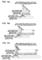
- Figs. 16a and 16b show four-branch tree nodes which are formed by collecting one of two-branch tree nodes A, B, C, D and E and two of two-branch tree nodes A0, A1, B0, B1, C0, C1, D0, D1, E0 and E1 just under the nodes A, B, C, D and E, three nodes in total, to form each of four-branch tree nodes 100, 101, 102, 103, and 104, and by disassembling three two-branch tree nodes to form the size of only lower two two-branch tree nodes. Disassemble is performed so as to satisfy the conditions that the same route search result is obtained both for the two-branch and four-branch tree nodes when the route search is performed in accordance with the specification of the longest coincidence search matching the route address mark length.
- a notation *A represents route information in the entry assigned to the node A.
- a node without the notation *A means that the entry is not assigned to this node.
- the two-branch tree structure has all three nodes ( Fig. 17a ) and entries are assigned to all nodes, the upper node is deleted and route information *A0 and *A1 of the lower nodes is left. This is because the route information *A of the node A is not used because if the entry of the node A is coincident, one of the entries of the nodes A0 and A1 becomes always coincident and the longest coincidence search is performed.
- the route information *A of the node A is stored in the node A1. If the lower node A0 among the nodes A0 and A1 is not assigned an entry, the same operation is performed.
- the route information *A of the node A is stored in both the nodes A0 and A1.
- the node A1 is added and the route information *A of the upper node A is stored in the node A. Since no node is connected below the node A1, a pointer to the node lower than the node A1 is set to NULL. The same operation is performed if the node A0 among the lower nodes A0 and A1 is not present.
- both the lower nodes A0 and A1 are not present ( Fig. 17e ). Both the nodes are added.
- the route information *A of the node A is stored in both the lower nodes and a pointer to the nodes lower than the nodes A0 and A1 is set to NULL.
- the lower node A1 is added. The same is applied if there is only the lower node A1.
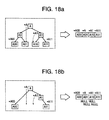
- the eight-branch tree is formed by disassembling a collection of seven two-branch nodes to leave only the lowest four nodes.
- Two examples of disassembling the upper three two-branch tree nodes are illustrated in Figs. 18a and 18b .
- Fig. 18a there are all seven two-branch tree nodes which are configured to one eight-branch tree node, and an entry is not assigned to some of the seven two-branch tree nodes.
- the nodes A01 and A10 not assigned an entry store the route information *A and *A1 of the upper nodes (A and A1) having an entry node and positioned at the lowest position among all the upper nodes, i.e., having the longest route address mask length.
- Fig. 18b there are only some of the seven two-branch tree nodes which are configured to one eight-branch tree node.
- the nodes A01 and A10 not present are added without an entry and route information is stored therein following the rule described with Fig. 18a .
- the added nodes A01 and A10 have no lower nodes so that a pointer to the lower node is set to NULL.
- a general p-th power-of-2-branch tree is formed by disassembling a collection of (p-th power of 2 - 1) two-branch nodes to leave only the lowest ((p-1)-th power of 2) nodes.
- Collections of 2, 4, 8,... two-branch tree nodes are used for 4, 8, 16,... -branch tree nodes. It is therefore possible to use only one of common elements of two-branch tree nodes to be collected for the 4, 8, 16,... -branch tree nodes.
- the memory capacity for the 4, 8, 16,... -branch tree nodes can be reduced.
- One of common elements of two-branch tree nodes to be collected for the 4, 8, 16,... -branch tree nodes includes a route address and a route address mask length at the node. As will be later described, since the route address mask length is not the route address mask length of the node itself, but the route address mask length of the node just under this node. Therefore, the effect of reducing the memory capacity cannot be obtained.
- a collection of two two-branch tree nodes is used to configure a four-branch tree node.
- the common data is only the route address at the node (words 124 and 125). If the sizes of the two two-branch tree nodes to be collected are different depending upon whether the route is assigned or not, the sizes of the four-branch tree nodes to be configured by respective two two-branch tree nodes are also different. Therefore, as shown in Fig. 12b , the transmission port information is separated from the node and this node stores a pointer to this transport information. Such two two-branch tree nodes are collected.
- a next node mask length tt, a flag tt and a next node pointer tt in words 120, 121, 122 and 123 are a value tt corresponding to the m-th and (m+1)-th bits where m if the route address mask length m of this node.
- the value tt may take 00, 01, 10, or 11.
- the flag 00 and flag 01 are set with the same value
- the flag 10 and flat 11 are also set with the same value.
- the two-branch tree node has a data size slightly larger than 16 bytes corresponding to a power of 2. If a four-branch tree node is used which has only one route address, the data size is just 32 bytes corresponding to a power of 2. If an eight-branch tree node is used which has only one route address, the data size is smaller than 64 bytes with empty 4 bytes in which other information can be stored. If the number of two-branch tree nodes to be collected is increased (i.e., if the value p of the p-th power-of-2-branch tree node is increased), the data size of one node can be made smaller relative to the size corresponding to a power of 2.
- the hardware structure can be made very simple. Examples of simplifying the hardware structure will be described.
- a memory area of one node does not ride over a bank boundary of a memory constituted of a plurality of banks. Even if a dynamic RAM is used as a memory, a memory area of one node does not ride over a row address boundary.
- a memory address if an address (hereinafter called a memory address) of each element in the node in a memory is to be calculated, an addition of a pointer to the node and an offset from the pointer is not performed, but the upper bits of the memory address are used as the value of the pointer and the lower bits thereof are used as the offset.
- the memory address of an element in the node can be generated by assigning the (fifth power of 2)-th bit and higher bits of the memory address to the pointer to the node and assigning the (0-th power of 2)-th to (fourth power of 2)-th bits of the memory address to the offset to the element in the node.
- a value of (start byte address of the next node)/3 is stored as the next node pointer in the node.
- the data amount of 5 bits per one pointer can be reduced in one node.
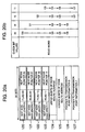
- a method of reading a node wherein, for example, the route search processing circuit 200 shown in Fig. 1 is made of a customized LSI will be described. If 4, 8, 16,... -branch tree nodes are used, the data size of each node is large. In this case, if all the data of one node is read from the memory storing the table into the customized LSI during the search process, a read time becomes longer as the node size becomes larger, resulting in a lowered performance. This problem can ba solved by reading only a portion of the node data without reading all the node data. This method will be described with reference to Figs. 20a and 20b .
- Figs. 20a and 20b show the data structure of a four-branch tree node.
- the four-branch tree node having a route address mask length m is constituted of a two-branch tree node corresponding to the m-th bit of "0" of the route address and a two-branch tree node corresponding to the m-th bit of "1" of the route address, as shown in Fig. 12b . Therefore, in accordance with the value of the m-th bit of the route address in a received packet, only the corresponding two-branch tree node is read so that even if the size of the node becomes large, the data amount same as that of the two-branch tree node is read.
- the route address (words 124 and 125) as one element to be stored for a collection of two two-branch tree nodes shown in Fig. 19 is read irrespective of what value the m-th bit of the route address in a received packet takes.
- one of the two next node pointers stored in the two-branch node is read to further reduce the read data amount.
- This method may be applied also to the two-branch tree searching method. For example, if a two-branch tree node has a route address mask length m, only one of the two next node pointers is read in accordance with the value of the m-th bit of the route address in a received packet.
- a node has a route address mask length m, in accordance with the values 00, 01, 10 or 11 of the m-th and (m+1)-th bits of the route address, the data is read in the order of respectively (word 120 ⁇ word 124 ⁇ word 125 ⁇ word 126), (word 121 ⁇ word 124 ⁇ word 125 ⁇ word 126), (word 122 ⁇ word 124 ⁇ word 125 ⁇ word 127), or (word 123 ⁇ word 124 ⁇ word 125 ⁇ word 127) ( Fig. 20b ).
- the route address mask length m of a node is required to be read at the start of reading the data of the node, or to move this information to the one-node preceding node and read it while the data of the preceding node is read.
- the method of reading the route address mask length m of the node at the start of reading the data of the node does not provide, however, good performance improvement effects of reading a portion of the node data. The reason for this is given in the following. For example, if the route search processing circuit 200 shown in Fig.
- the method of moving data of the route address mask length m to the preceding node and reading it while the data of the preceding node is read, provides better performance improvement effects.
- the data of one node is read in the order of the next node route address mask length m, next node pointer, route address at the node, and then pointer to the transmission port information, so that a memory address of a data area to be first read from the next node can be calculated fastest.
- the next node pointer indicates the top area of the memory area of the next node.
- the offset of the memory address from the top area of the next node to the data area to be first read can be obtained by reading the route address mask length m of the next node and checking the value of the corresponding bit position of the route address in a received packet.
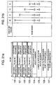
- Figs. 21a and 21b show the data structure of a four-branch tree. As described with the two-branch tree structure, in a general tree structure, an entry is not always assigned to all nodes. At a branch of the tree, it is necessary to provide a node even if an entry is not assigned. As shown in Figs. 21a and 21b , in accordance with the values of the entry flags in the words 120, 121, 122, and 123 of the node data to be first read, the pointer to the transmission port information is not read if the node is not assigned an entry, to thereby shorten a read time. Since the entry flag can be expressed by 1 bit, an increase in the read time by reading this information is small.
- the word 120 is read, and if it is judged from the flag 00 that the 0-th two-branch tree constituting the four-branch tree has no route information, only the words 124 and 125 are read. Only when it is judged that there is route information, the words 124, 125 and 126 are read in this order as shown in Fig. 21b .
- the same operation is also applied if the values of the m-th and (m+1)-th bits of the route address are 01, 10 and 11.
- the two-branch tree searching method (first method), p-th power-of-2-branch searching method (second method) and method (third method) of developing a node having a route address mask length m have been described above.
- the route searching operation to be executed by the route search processing circuit 200 shown in Fig. 1 will be described with reference to the flow chart shown in Fig. 22 which illustrates an operation by a combination of the second and third methods.
- the route searching operation to be executed by the route search processing circuit 200 shown in Fig. 1 will be described with reference to the flow chart shown in Fig. 22 which illustrates an operation by a combination of the second and third methods.
- the route searching operation to be executed by the route search processing circuit 200 shown in Fig. 1 will be described with reference to the flow chart shown in Fig. 22 which illustrates an operation by a combination of the second and third methods.
- the p-th power-of-2-branch tree nodes developed on a memory at predetermined positions is selected.
- the route address at the m-th bit to the last bit is checked by every p bits to check the p-th power-of-2-branch tree. It is assumed that the memory 300 shown in Fig. 1 stores the p-th power-of-2-branch tree node data in conformity with the second and third searching methods and transmission port information.
- the route searching operation can be realized either by software or hardware. If it is to be realized by software, a CPU is used in place of the route search processing circuit 200 shown in Fig. 1 . If it is realized by hardware, a customized LSI is used in place of the route search processing circuit 200 shown in Fig. 1 .
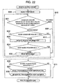
- a process 810 shown in Fig. 22 is a tree structure search process.
- a process 811 is a transmission port information process. First, the tree structure search process 810 will be described.
- the route search processing circuit 200 shown in Fig. 1 Upon reception of the receiver multicast group ID and a sender IP address in a received packet, the route search processing circuit 200 shown in Fig. 1 generates a route address described with reference to Fig. 5 , from the received group ID and IP address. In accordance with the route address and the value of the mask length m of the first node, a pointer to the first node is generated. In accordance with the values (hereinafter called check bit value) of the m-th and (m+p-1)-th bits of the route address, a read address of the first node stored in the memory 300 is generated to read a portion of the first node data from the memory 300 (at 800 in Fig. 22 ).
- the route search processing circuit 200 shown in Fig. 1 compares the route address at the node with the upper effective bits of the route address in the received packet masked by the mask length (at 801 in Fig. 22 ). If they are not coincident, the tree structure search process is terminated (at 809 in fig. 22 ), whereas if coincident, the flow advances to a process 802 shown in Fig. 22 .
- the routes information includes an entry flag and a pointer to the transmission port information among the node data output from the memory 300 shown in Fig. 1 .
- the route search processing circuit 200 shown in Fig. 1 checks the entry flag in the node data. Only if the entry flag is "1" (at 812 in Fig. 22 ), new route information in the read node data is loaded in a register (at 803 in Fig. 22 ), whereas if the entry flag is "0", the update process is not performed (at 813 in Fig. 22 ).
- the route search processing circuit 200 shown in Fig. 1 judges whether the next node pointer in the node data output from the memory 300 shown in Fig. 1 is NULL (at 804 in Fig. 22 ). If NULL, the tree search process 810 is terminated, whereas if not NULL, a read address of the first node data stored in the memory 300 is generated in accordance with the pointer and the new check bit values, to thereby read the node data from the memory 300 (at 805 in Fig. 22 ).
- the transmission port information process 811 shown in Fig. 22 will be described.
- the register of the route search processing circuit 200 shown in Fig. 1 has as the route information, the entry flag and the pointer to the transmission port information.
- the route search processing circuit 200 shown in Fig. 1 first checks the entry flag loaded in the register (at 806 in Fig. 22 ). If the entry flag value is "0", the route search process is terminated and a notice of no search result is supplied to the transfer processing unit 504. If the entry flag value is "1", it means that the search result shows a coincidence of a certain entry. In this case, therefore, by using the pointer to the transmission port information, the transmission port information is read from the memory 300 (at 807 in Fig. 22 ). By using this transmission port information, one or a plurality of port numbers for packet transmission are generated and supplied to the transfer processing unit 504 shown in Fig. 1 (at 808 in Fig. 22 ). After all the port numbers are transmitted, the route search process is terminated.
- the route search processing circuit 200 includes a tree structure search circuit 201, a read address generator circuit 202, a memory control circuit 206, a transmission port information processing circuit 203 and a route search processing control circuit 204.
- the tree structure search circuit 201 searches the p-th power-of-2-branch tree structure stored in the memory 300 to generate the next node pointer, derive the check bit values from the route address in a received packet, judge the completion of the tree structure search, and update the candidate of the route information as the search result.
- the read address generator circuit 202 generates a memory address of a word to be read in the node in the sequential order descried with Figs. 20a and 20b , in accordance with the next node pointer and check bit values output from the tree structure search circuit 201 and a timing signal output from the route search processing control circuit 204.
- the read address generator circuit 202 supplies the generated memory address to the memory control circuit 206.
- the read address generator circuit 202 generates a memory address of the transmission port information by using the pointer to the transmission port information loaded in a register of the tree structure search circuit 201 as the search result.
- the memory control circuit 206 generates a memory control signal in accordance with the supplied memory address and the timing signal output from the route search processing control circuit 204.
- the transmission port information processing circuit 203 generates one or a plurality of port numbers for packet transmission by using the transmission port information read from the memory 300, and transmits the port numbers to the transfer processing unit 504.
- the route search processing control circuit 204 controls the whole of the route search processing circuit 200, such as an operation timing and operation status management of each circuit.
- the memory 300 may be provided directly from the customized LSI or may use a built-in memory of the customized LSI. As compared to the discrete memory, the built-in memory of the customized LSI has a shorter memory access time so that the search process for the routing table stored in the memory 300 can be performed at high speed.
- the tree structure search circuit 201 Upon reception of the receiver multicast group ID and a sender IP address in a received packet from the transfer processing unit 504, the tree structure search circuit 201 generates a route address from the received group ID and IP address. In accordance with the route address and the value of the mask length m of the node, a next node pointer is generated and transferred to the read address generator circuit 202. The tree structure search circuit 201 derives the values (check bit values) of the check bit positions of the route address indicated by the node mask length, and transfers the values to the read address generator circuit 202.
- the read address generator circuit 202 generates a memory address of a word to be read in the node in the sequential order descried with Figs. 20a and 20b , in accordance with the next node pointer and check bit values and a timing signal output from the route search processing control circuit 204, and transmits the generated memory address to the memory control circuit 206.
- the memory control circuit 206 generates a memory control signal by using the memory address and a timing signal supplied from the route search processing control circuit, and outputs the memory control signal to the memory 300.
- the memory 300 Upon reception of the memory control signal, the memory 300 transfers the corresponding node data to the tree structure search circuit via a signal line 214.
- the tree structure search circuit 200 performs the processes 801, 802, 803, 804 and 805 shown in Fig. 22 .
- the details of these processes will be given later with reference to Fig. 24 . If the judgement process corresponding to the processes 801 and 804 shown in Fig. 22 judges that the tree structure search is completed, a tree structure search completion signal is supplied to the route search processing control circuit 204 which starts a transmission port information read process. If it is not judged as a tree structure search completion, the processes 801, 802, 803, 804 and 805 shown in Fig. 22 are repeated until the tree structure search completion.
- the route search processing control circuit 204 checks the entry flag in the rout information (entry flag, pointer to transmission port information) stored in the tree structure search circuit 201. If the entry flag is "0", the route search process is terminated and a notice of no search result is supplied to the transfer processing unit 504. If the entry flag is "1", a transmission port information read and transmission port generation control process starts and the tree structure search circuit 201 is controlled to output the pointer to the transmission port information to the read address generator circuit 202. By using the pointer to the transmission port information and a timing signal output from the route search processing circuit 204, the read address generator circuit 204 generates a memory address of the transmission port information to be read, and transmits the generated memory address to the memory control circuit 206.
- the memory control circuit 206 In accordance with the memory address and a timing signal output from the route search processing control circuit 204, the memory control circuit 206 generates a memory control signal and transmits it to the memory 300. Upon reception of this control signal, the memory 300 outputs the transmission port information to the signal line 214. Upon reception of this transmission port information, the transmission port information processing circuit 203 generates one or a plurality of port numbers for packet transmission and transmits the port numbers to the transfer processing unit 504.
- the structure of transmission port information may be a list structure which interconnects a plurality of transmission port numbers by pointers or a bitmap of transmission port numbers. If the list structure is used, the number of memory accesses increases as the number of transmission port numbers increases, so that the search process takes a time.
- a bit map of transmission port numbers can be burst-read from the memory 300 and stored in the transmission port information processing circuit 203. Then, the bit map is decoded to generate the transmission port numbers. In this case, the number of memory accesses can be reduced.
- the route search processing control circuit 204 terminates the route search process and controls the next packet.
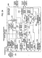
- the receiver multicast group address and sender IP address transmitted via a signal line 205 from the transfer processing unit 504 are stored in a route address generator circuit 207.
- the route address generator circuit 207 generates a route address 33 of 60 bits described with reference to Fig. 5b and outputs it to a first node pointer generator circuit 208, a check bit deriving circuit 209 and a masking circuit 210.
- the first node pointer generator circuit 208 derives the values from the 0-th bit to the (m-1)-th bits of the route address in a received packet, and in accordance with these m-bit values, generates the first node pointer to output it to a pointer selector 211.
- the pointer selector 211 selects the first node pointer for reading the first node data and outputs it to the read address generator circuit 202 shown in Fig. 23 .
- the pointer selector 211 selects the next node pointer loaded in a next node pointer register 215 and outputs it to the read address generator circuit 202.
- the check bit deriving circuit 209 refers to the value m selected by the check bit position selector 212 and set in the first stage node mark register 229 and derives p-bit check bits from the m-th bit to the (m+P-1)-th bits of the route address and outputs them to the read address generator circuit 202 shown in Fig. 23 , for the start node read.
- the next node mask length m1 loaded in a next node mask length register 216 to be later described is selected by the check bit position selector 212 and output to the check bit deriving circuit 209.
- the check bit deriving circuit 209 derives p-bit check bits from the m1-th bit to the (m1+p-1)-th bit of the route address, and outputs them to the read address generator circuit 202 shown in Fig. 23 .
- the read address generator circuit 202 and memory control circuit 206 shown in Fig. 23 generate a memory address of a word in the node to be read and a memory control signal in the sequential order described with reference to Figs. 20a and 20b by using the node pointer and p-bit check bits, and the memory 300 reads the word of the node at the supplied memory address and outputs it to the signal line 214.
- the number of words per one node read is four words if the method described with Figs. 20a and 20b is adopted.
- the data of four words is output to the signal line 214 in the order shown in Figs. 20a and 20b and loaded in respective registers (next node pointer register 215, next node mask length register 216, route address upper register 217, route address lower register 222, flag register 224, and transmission port information pointer register 230).
- a load timing of each register is controlled by a control signal (not shown) supplied from the route search processing control circuit 204.
- next node pointer register 215 stores the next node pointer
- the next node mask length register 216 stores the next node mask length
- the route address upper register 217 stores the upper 28 bits of the route address at the node
- the route address lower register 222 stores the lower 32 bits of the route address
- the flag register 224 stores the entry flag
- the transmission port information pointer register 230 stores a pointer to the transmission port information.
- the node mask length loaded in the mask length register 227 is input via the mask length selector 228 to the masking circuit 210.
- a value of the mask length register 227 is a value of the next node mask length stored in the one-node preceding node data and loaded in the next node mask length register 216.
- a value in the next node mask length register 216 is updated each time the node data is read. Therefore, before it is updated, a mask length of a presently read node (hereinafter called present node) data to be used for the route address coincidence comparison process is loaded in the mask length register 227.
- the masking circuit 210 generates a mask which validates the upper bits corresponding to the mask length.
- the masking circuit calculates a logical product of this mask and the route address in a received packet output from the route address generator circuit 207, and outputs the logical products (hereinafter called a masked route address in the received packet) to a coincidence comparator circuit 213.
- the upper 28 bits and lower 32 bits of the route address at the node stored in the route address upper register 217 and route address lower register 222 are coupled in this order and input to the coincidence comparator circuit 213 as the route address at the node.
- the coincidence comparator circuit 213 compares the route address at the node with the masked route address in the received packet (hereinafter called a route address comparison).
- an incoincidence signal is transferred via a signal line 218 to a tree search completion judging circuit 219.
- the tree search completion judging circuit 219 Upon reception of the incoincidence signal, the tree search completion judging circuit 219 transmits a tree structure search completion signal to the route search processing control circuit 204 shown in Fig. 23 .
- the value in the mask length register 227 is updated by the value of the next node mask length stored in the next node mask length register 216, the updated value being used for the route address comparison when the next node data is read.
- the coincidence comparator circuit 213 If the route address comparison by the coincidence comparator circuit 213 indicates a coincidence, the coincidence comparator circuit 213 outputs a coincidence signal to an update judging circuit 221 via a signal line 220. Only when this coincidence signal is input to the update judging circuit 221 and the entry flag value stored in the flag register 224 is "1" (at 812 in Fig. 22 ), the update judging circuit 221 outputs an update signal to the flag register 223 and transmission port information pointer register 225. Upon reception of the update signal, the flag register 223 stores the new entry flag stored in the flag register 224.
- the transmission port information pointer register 225 stores the new transmission port information pointer register stored in the transmission port information pointer register 230 (the route information updating process 803 in Fig. 22 ). If the value of the entry flag is "0", the update judging circuit 221 does not transmit the update signal so that the update process is not performed by the flag register 223 and transmission port information pointer register 225 (at 813 in Fig. 22 ).
- next node pointer stored in the next node pointer register 215 is input to the tree search completion judging circuit 219. If the next node pointer is NULL, the tree search completion judging circuit 219 outputs a tree search completion signal to the route search processing control circuit 204 shown in Fig. 23 .
- each of the processes 801, 802, 803, 804 and 805 in the tree structure search operation shown in Fig. 22 is not required to be executed time sequentially, but each process can start after data necessary for each process is stored in each of the registers 215, 216, 217, 222, 224 and 223. By executing each process in parallel, the tree structure can be searched at high speed.
- the receiver multicast group address and sender IP address used for a search key for the multicast route search are coupled in this order and defined as one route address.
- the multicast routing table is configured as a two-branch tree. Accordingly, even if the number of entries increases, the search process can be performed without prolonging a search time.
- the number of branches of each node constituting a search tree is increased by a power of 2, from a conventional two-branch tree node to a four-branch tree node, an eight-branch tree node, or more. It is possible to check not one bit per one node, but consecutive two bits, three bits, or more at the same time. The number of nodes to the search completion therefore reduces and the route search process can be performed at high speed.
- Fig. 25 is a graph showing a multicast route search process performance 900 of the hash method of the second prior art, a multicast route search process performance 901 of the two-branch tree of this invention, a multicast route search process performance of the p-th power-of-2-branch tree of this invention (e.g., performance 902 of a four-branch tree, performance 903 of an eight-branch tree), relative to the number of entries.
- the process performance of the hash method degrades in inverse proportion with the number of entries, whereas the process performance of the two-branch tree and p-th power-of-2-branch tree is constant and does not depend upon the number of entries.
- the four-branch tree realizes the performance better than the two-branch tree by a twofold, and the eight-branch tree by a threefold.
- the multicast group address itself is not used but the multicast group ID of the lower 28 bits of the multicast group address and the sender IP address coupled in this order are used.
- the multicast routing table is configured as a two-branch tree or a p-th power-of-2-branch tree. It is therefore possible to reduce the number of bits of the route address for determining the depth of a search tree and to reduce the maximum number of nodes to be traced.
- an eight-branch tree or generally a p-th power-of-2-branch tree a collection of one two-branch tree node and two-branch tree nodes of (p-1) stages, totalling in ((a p-th power of 2) - 1) nodes just under the one upper node, is used as one p-th power-of-2-branch tree node.
- the (p-1)-th power of 2) two-branch nodes at the lowest stage collected are embedded with the entry data assigned to the nodes at the higher stages. Accordingly, the memory capacity corresponding to ((a p-th power of 2) - 1) two-branch tree nodes before the collection can be reduced to the memory capacity corresponding to ((p-1)-th power of 2) two-branch tree nodes.
- the transmission port information is separated from the node data of the search tree and stored in another area of a memory.
- the data amount of the two-branch tree node assigned an entry becomes equal to the data amount of the two-branch tree node not assigned an entry.
- the memory capacity for the p-th power-of-2-branch tree node can be reduced and the memory amount of each p-th power-of-2-branch tree node can be made equal.
- All the data of the four-branch tree node, eight-branch tree node, or node having branches more than these configured by a collection of a plurality of two-branch tree nodes, is not read during the search, but only a necessary portion of the data is read. It is therefore possible to prevent a data read time from being made longer by a large node size and speed up the route search process.
- Each node stores not the mask length of its own, but the mask length of a node connected just under the node. Accordingly, the mask length of the node can be known before the data of the node is read. Also, which area of the node is read can be known before the data of the node is actually read and only the necessary data can be read. It is therefore possible to prevent a data read time from being made longer by a large node size and speed up the route search process.
- a flag is provided which indicates whether the node is assigned an entry. This flag is first read, and if the entry is not assigned, the route information of this node is not read. It is therefore possible to shorten a data read time and speed up the route search process.
- Nodes corresponding in number to the upper several bits of the route address are developed on a memory at predetermined positions.
- the memory area where the node data is stored is directly accessed. It is therefore possible to omit this search process time and the route search process can be performed at high speed.
- Such high speed operation means may be realized by hardware to speed up the route search process.
Landscapes
- Engineering & Computer Science (AREA)
- Computer Networks & Wireless Communication (AREA)
- Signal Processing (AREA)
- Data Exchanges In Wide-Area Networks (AREA)
- Small-Scale Networks (AREA)
- Computer And Data Communications (AREA)
- Communication Control (AREA)
Claims (18)
- Dispositif de relais de paquet pour rechercher des informations de trajet d'un paquet de multidiffusion reçu en utilisant en tant que clé de recherche une adresse du récepteur et une adresse de l'émetteur du paquet de multidiffusion reçu et transférer le paquet de multidiffusion à un port ou à une pluralité de ports conformément aux informations de trajet, le dispositif de relais de paquet comportant :des moyens de mémorisation (300) pour mémoriser des informations d'un arbre de recherche d'une structure arborescente à deux branches correspondant à une configuration binaire d'une adresse de trajet couplant l'adresse du récepteur et l'adresse de l'émetteur, etdes moyens de détermination de coïncidence (200) pour dériver l'adresse du récepteur et l'adresse de l'émetteur du paquet de multidiffusion reçu, générer l'adresse de trajet en couplant l'adresse du récepteur et l'adresse de l'émetteur dérivées, et exécuter une détermination de coïncidence pour déterminer si l'adresse de trajet générée coïncide avec l'adresse de trajet mémorisée dans lesdits moyens de mémorisation.
- Dispositif selon la revendication 1, dans lequel les moyens de détermination de coïncidence (200) sont adaptés pour exécuter le couplage de l'adresse du récepteur et de l'adresse de l'émetteur dérivées dans cet ordre.
- Dispositif selon la revendication 1, dans lequel lesdits moyens de détermination de coïncidence (200) sont adaptés pour exécuter la détermination de coïncidence si chaque bit en commençant par un bit supérieur de l'adresse de trajet générée à partir du paquet de multidiffusion reçu coïncide avec un bit correspondant de l'adresse de trajet mémorisée dans lesdits moyens de mémorisation.
- Dispositif selon la revendication 1, dans lequel les moyens de détermination de coïncidence (200) sont adaptés pour exécuter une détermination de coïncidence afin de déterminer si l'adresse du récepteur dérivée coïncide avec une partie correspondante de l'adresse de trajet mémorisée dans lesdits moyens de mémorisation, et pour exécuter une détermination de coïncidence afin de déterminer si l'adresse de l'émetteur dérivée coïncide avec une partie correspondante de l'adresse de trajet mémorisée dans lesdits moyens de mémorisation.
- Dispositif selon la revendication 4, dans lequel lesdits moyens de détermination de coïncidence (200) sont adaptés pour exécuter une détermination de coïncidence afin de déterminer si l'adresse du récepteur dérivée du paquet de multidiffusion reçu coïncide avec une partie correspondante de l'adresse de trajet mémorisée dans lesdits moyens de mémorisation, avant d'exécuter une détermination de coïncidence pour déterminer si l'adresse de l'émetteur dérivée du paquet de multidiffusion reçu coïncide avec une partie correspondante de l'adresse de trajet mémorisée dans lesdits moyens de mémorisation.
- Dispositif selon la revendication 1, comportant en outre un circuit (200) pour rechercher un arbre de recherche de la structure arborescente à deux branches mémorisé dans lesdits moyens de mémorisation conformément à une valeur de chaque bit contrôlé en commençant par un bit supérieur de l'adresse de trajet couplant l'adresse du récepteur et l'adresse de l'émetteur dans le paquet de multidiffusion reçu.
- Dispositif selon la revendication 2, dans lequel le circuit (200) est adapté pour rechercher l'arbre de recherche de la structure arborescente à deux branches mémorisé dans lesdits moyens de mémorisation conformément à une valeur de chaque bit contrôlé en commençant par un bit supérieur de l'adresse de trajet couplant l'adresse du récepteur et l'adresse de l'émetteur dans le paquet de multidiffusion reçu dans cet ordre.
- Dispositif selon la revendication 2, dans lequel le circuit (200) est adapté pour rechercher l'arbre de recherche de la structure arborescente à deux branches mémorisé dans lesdits moyens de mémorisation conformément à une valeur de chaque bit contrôlé en commençant par un mème bit de l'adresse de trajet, en développant (mème puissance de 2) noeuds d'arborescence à deux branches correspondants aux m bits supérieurs de l'adresse de trajet sur lesdits moyens de mémorisation à des positions prédéterminées, chaque noeud étant défini selon une correspondance bi-univoque avec chaque valeur pouvant être prise par les 0ème à (m-1)ème bits de l'adresse de trajet, et en sélectionnant l'un des noeuds développés conformément à des valeurs des 0ème à (m-1)ème bits de l'adresse de trajet pour rechercher l'arbre de recherche.
- Dispositif selon l'une quelconque des revendications 1, 2 et 4 à 8, dans lequel une structure arborescente à pème puissance 2 branches (p étant un nombre naturel) est utilisée à la place de ladite structure arborescente à 2 branches.
- Dispositif selon la revendication 9, dans lequel lesdits moyens de détermination de coïncidence (200) sont adaptés pour exécuter une détermination de coïncidence afin de déterminer si tous les p bits en commençant par un bit supérieur de l'adresse de trajet générée à partir du paquet de multidiffusion reçu coïncident avec les p bits correspondants de l'adresse de trajet mémorisée dans lesdits moyens de mémorisation.
- Dispositif selon la revendication 7, dans lequel les informations d'arbres de recherche sont configurées en utilisant une collection d'un noeud d'arborescence à deux branches et de noeuds d'arborescence à deux branches de (p-1) étages totalisant (pème puissance 2) - 1) noeuds juste au-dessous du noeud d'arborescence à deux branches, en tant que noeud à pème puissance 2 branches, et en incorporant, dans ((p-1)ème puissance 2) noeuds à 2 branches au niveau de l'étage le plus bas de la collection, des données d'entrée attribuées aux noeuds à l'étage plus élevé que l'étage le plus bas, de manière à former un noeud à pème puissance 1 branches en utilisant ((p-1)ème puissance 2) noeuds à deux branches.
- Dispositif selon la revendication 7, dans lequel une collection d'un noeud d'arborescence à deux branches et de noeuds d'arborescence à deux branches de (p-1) étages totalisant (pème puissance 2) - 1) noeuds juste au-dessous du noeud d'arborescence à deux branches, est utilisée en tant que noeud à pème puissance 2 branches, et des données d'entrée attribuées aux noeuds au niveau de l'étage plus élevé que l'étage le plus bas sont incorporées dans ((p-1)ème puissance 2) noeuds à deux branches au niveau de l'étage le plus bas de la collection de manières à former un noeud à pème puissance 2 branches en utilisant ((p-1)ème puissance 2) noeuds à deux branches, et lorsqu'une pluralité de noeuds d'arborescence à deux branches sont collectés, seul un élément unique de données d'entrée est incorporé si l'élément unique est suffisant.
- Dispositif selon la revendication 9 lorsqu'elle dépend de la revendication 8, dans lequel lorsque des données d'un noeud pème puissance 2 branches sont lues pour une recherche de trajet, toutes les données ne sont pas lues mais uniquement les données correspondant à l'un des noeuds parmi les ((p-1)ème puissance 2) noeuds à 2 branches collectés pour la pème puissance 1 branche sont lues.
- Dispositif selon la revendication 12, dans lequel chaque noeud ne mémorise pas une longueur de masque du noeud lui-même, mais mémorise une longueur de masque d'un autre noeud connecté juste au-dessous du noeud, la longueur du masque de l'autre noeud est connue avant que des données de l'autre noeud soient lues, et des données à lire à partir de l'autre noeud sont sélectionnés conformément à des valeurs à partir d'une position binaire de l'adresse de trajet indiquée par la longueur de masque de l'autre noeud jusqu'à une position de la position binaire ajoutée à (p-1).
- Dispositif selon la revendication 11, dans lequel si plusieurs bits supérieurs de l'adresse du récepteur du paquet de multidiffusion sont utilisés en tant que bits d'identification pour le paquet de multidiffusion, l'adresse de trajet est formée en couplant l'adresse du récepteur sans les bits identification et l'adresse de l'émetteur.
- Dispositif selon la revendication 7, dans lequel des informations de port de transmission à obtenir en tant que résultat de recherche sont séparées de données de l'arbre de recherche et mémorisées dans une autre zone desdits moyens de mémorisation et une adresse des informations de port de transmission séparées est mémorisée dans les données de l'arbre de recherche.
- Procédé consistant à rechercher, en utilisant une adresse de trajet qui couple une adresse du récepteur et une adresse de l'émetteur à partir d'un paquet reçu dans un routeur, une adresse d'un port et un routeur ou un hôte auquel le paquet est ensuite délivré en sortie, comportant les étapes consistant à :exécuter une recherche d'arbre à 2 branches dans laquelle chaque bit en commençant par un bit supérieur d'une adresse de trajet est contrôlé un bit après l'autre,exécuter une recherche de coïncidence masquée en amenant une position binaire à contrôler à correspondre à une longueur de masque, etdéfinir un indicateur agencé dans une donnée de chaque noeud d'un arbre de recherche à lire en premier indiquant si une entrée est attribuée au noeud, après quoi l'indicateur est lu en premier et, si l'entrée n'est pas attribuée au noeud, des informations de trajet de ce noeud ne sont pas lues de manière à raccourcir un temps de lecture des données et à accélérer un processus de recherche.
- Circuit d'intégration à grande échelle, LSI, personnalisé pour recevoir des informations d'entête d'un paquet de multidiffusion et rechercher et délivrer en sortie des informations de transfert tel qu'un port de transmission du paquet de multidiffusion, le circuit LSI personnalisé comportant :un circuit (200) pour contrôler p bits en commençant par un bit supérieur d'une adresse de trajet couplant une adresse du récepteur et une adresse de l'émetteur du paquet de multidiffusion dans cet ordre, et pour rechercher un arbre de recherche d'une structure arborescente à pème puissance 2 branches (P est un nombre naturel) mémorisé dans des moyens de mémorisation conformément à des valeurs des p bits contrôlés.
Applications Claiming Priority (2)
| Application Number | Priority Date | Filing Date | Title |
|---|---|---|---|
| JP28220598A JP3735471B2 (ja) | 1998-10-05 | 1998-10-05 | パケット中継装置およびlsi |
| JP28220598 | 1998-10-05 |
Publications (3)
| Publication Number | Publication Date |
|---|---|
| EP0993144A2 EP0993144A2 (fr) | 2000-04-12 |
| EP0993144A3 EP0993144A3 (fr) | 2005-12-14 |
| EP0993144B1 true EP0993144B1 (fr) | 2010-10-13 |
Family
ID=17649444
Family Applications (1)
| Application Number | Title | Priority Date | Filing Date |
|---|---|---|---|
| EP19990117151 Expired - Lifetime EP0993144B1 (fr) | 1998-10-05 | 1999-08-31 | Appareil de relais de paquets et méthode et circuit correspondants |
Country Status (5)
| Country | Link |
|---|---|
| US (1) | US6778532B1 (fr) |
| EP (1) | EP0993144B1 (fr) |
| JP (1) | JP3735471B2 (fr) |
| CA (1) | CA2281018C (fr) |
| DE (1) | DE69942850D1 (fr) |
Families Citing this family (71)
| Publication number | Priority date | Publication date | Assignee | Title |
|---|---|---|---|---|
| WO1999049618A1 (fr) | 1998-03-23 | 1999-09-30 | Hitachi, Ltd. | Repeteur reseau et procede de recherche de destination de transfert suivante dans le reseau |
| JP2001186142A (ja) * | 1999-12-27 | 2001-07-06 | Toshiba Corp | パケットバッファ装置、及び、パケットスイッチ装置 |
| US7089240B2 (en) | 2000-04-06 | 2006-08-08 | International Business Machines Corporation | Longest prefix match lookup using hash function |
| US7111071B1 (en) * | 2000-06-29 | 2006-09-19 | Intel Corporation | Longest prefix match for IP routers |
| US7310335B1 (en) * | 2000-09-06 | 2007-12-18 | Nokia Networks | Multicast routing in ad-hoc networks |
| JP4151217B2 (ja) * | 2000-12-15 | 2008-09-17 | 沖電気工業株式会社 | データグラム転送装置 |
| JP3589349B2 (ja) * | 2001-01-12 | 2004-11-17 | 日本電気株式会社 | 経路検索システムとその検索方法、及び経路検索プログラムを記録した記録媒体 |
| DE50107611D1 (de) | 2001-04-07 | 2005-11-10 | Vector Informatik Gmbh | Verfahren und Generierungsmodul zur Ermittlung von Filtermasken zur Relevanzprüfung von Kennzeichnern |
| US20030026246A1 (en) * | 2001-06-06 | 2003-02-06 | Zarlink Semiconductor V.N. Inc. | Cached IP routing tree for longest prefix search |
| US7126944B2 (en) * | 2001-07-05 | 2006-10-24 | Intel Corporation | Routing packets across multiple forwarding elements |
| US7103054B2 (en) * | 2001-07-16 | 2006-09-05 | International Business Machines Corporation | Methods and arrangements for building a subsource address multicast distribution tree using point to point routing records |
| JP2003032287A (ja) * | 2001-07-16 | 2003-01-31 | Furukawa Electric Co Ltd:The | ネットワーク間接続方法、その装置およびその装置を用いたシステム |
| US6925503B2 (en) * | 2001-07-27 | 2005-08-02 | International Business Machines Corporation | Method and system for performing a longest prefix match search |
| IL145040A0 (en) * | 2001-08-21 | 2002-06-30 | Infocyclone Inc | Tree search unit |
| US7110404B1 (en) * | 2001-09-04 | 2006-09-19 | Cisco Technology, Inc. | System and method for sending a packet to multiple destinations using a pipeline network processor |
| KR100418562B1 (ko) * | 2001-09-06 | 2004-02-14 | 주식회사 기지소프트 | 다중전송을 위한 중계경로 생성방법 |
| US8385361B2 (en) * | 2001-10-19 | 2013-02-26 | Intellectual Ventures I Llc | Multicast transmission to a radio access network |
| JP4048861B2 (ja) * | 2002-07-23 | 2008-02-20 | 日本電気株式会社 | アドレス検索装置 |
| US7263099B1 (en) | 2002-08-14 | 2007-08-28 | Juniper Networks, Inc. | Multicast packet replication |
| US7362744B2 (en) * | 2002-08-15 | 2008-04-22 | International Business Machines Corporation | Database management system and method of using it to transmit packets |
| US7346009B2 (en) * | 2002-09-30 | 2008-03-18 | Mosaid Technologies, Inc. | Dense mode coding scheme |
| US7389353B2 (en) * | 2003-01-22 | 2008-06-17 | Nokia Corporation | Method, system and mirror driver for LAN mirroring |
| JP2004282255A (ja) * | 2003-03-13 | 2004-10-07 | Matsushita Electric Ind Co Ltd | 通信システム |
| JP3813136B2 (ja) * | 2003-04-25 | 2006-08-23 | インターナショナル・ビジネス・マシーンズ・コーポレーション | 通信制御装置、通信制御方法、通信制御プログラム、通信制御用データ構造 |
| US7564842B2 (en) * | 2003-07-02 | 2009-07-21 | Mitsubishi Electric Research Laboratories, Inc. | Methods and apparatuses for routing data in a personal area network |
| WO2005048501A2 (fr) * | 2003-10-30 | 2005-05-26 | Teak Technologies, Inc. | Ordonnancement de paquets a multidiffusion multidebits de maniere non bloquante et deterministe |
| US7594996B2 (en) | 2004-01-23 | 2009-09-29 | Aquatech, Llc | Petroleum recovery and cleaning system and process |
| US7519733B1 (en) * | 2004-05-13 | 2009-04-14 | Cisco Technology, Inc. | Arrangement in a router for establishing multicast group hierarchy and coalescence |
| US7484022B1 (en) | 2004-08-27 | 2009-01-27 | Xilinx, Inc. | Network media access controller embedded in a programmable logic device—host interface |
| US7143218B1 (en) | 2004-08-27 | 2006-11-28 | Xilinx, Inc. | Network media access controller embedded in a programmable logic device-address filter |
| TWI277325B (en) * | 2005-10-28 | 2007-03-21 | Ind Tech Res Inst | Packet transmitting method of wireless network |
| GB0524126D0 (en) | 2005-11-26 | 2006-01-04 | Cogniscience Ltd | Data transmission method |
| US20110174307A1 (en) * | 2006-01-04 | 2011-07-21 | Lessi Stephane | Device for Supplying Oxygen to the Occupants of an Aircraft and Pressure Regulator for Such a Device |
| WO2008032709A1 (fr) * | 2006-09-15 | 2008-03-20 | Nec Corporation | SystÈme de distribution de paquet et procÉDÉ de distribution de paquet |
| CN101296020A (zh) * | 2007-04-27 | 2008-10-29 | 北京三星通信技术研究有限公司 | 部分功能ofdma中继系统直接消息转发的实现方法 |
| CN101141389B (zh) * | 2007-09-29 | 2010-06-16 | 华为技术有限公司 | 增强多位Trie树查找方法和装置 |
| KR100929116B1 (ko) * | 2007-12-10 | 2009-11-30 | 한국전자통신연구원 | 헤드엔드 케이블모뎀을 위한 멀티캐스트 서비스 플로우처리 방법 및 장치 |
| US8114117B2 (en) * | 2008-09-30 | 2012-02-14 | Tyco Healthcare Group Lp | Compression device with wear area |
| US8675648B1 (en) | 2008-09-30 | 2014-03-18 | Juniper Networks, Inc. | Methods and apparatus for compression in packet classification |
| US8798057B1 (en) | 2008-09-30 | 2014-08-05 | Juniper Networks, Inc. | Methods and apparatus to implement except condition during data packet classification |
| US8804950B1 (en) | 2008-09-30 | 2014-08-12 | Juniper Networks, Inc. | Methods and apparatus for producing a hash value based on a hash function |
| US7738454B1 (en) * | 2008-09-30 | 2010-06-15 | Juniper Networks, Inc. | Methods and apparatus related to packet classification based on range values |
| US7796541B1 (en) | 2008-09-30 | 2010-09-14 | Juniper Networks, Inc. | Methods and apparatus for range matching during packet classification based on a linked-node structure |
| US7835357B2 (en) * | 2008-09-30 | 2010-11-16 | Juniper Networks, Inc. | Methods and apparatus for packet classification based on policy vectors |
| US7961734B2 (en) * | 2008-09-30 | 2011-06-14 | Juniper Networks, Inc. | Methods and apparatus related to packet classification associated with a multi-stage switch |
| US8111697B1 (en) | 2008-12-31 | 2012-02-07 | Juniper Networks, Inc. | Methods and apparatus for packet classification based on multiple conditions |
| US7889741B1 (en) | 2008-12-31 | 2011-02-15 | Juniper Networks, Inc. | Methods and apparatus for packet classification based on multiple conditions |
| US8488588B1 (en) | 2008-12-31 | 2013-07-16 | Juniper Networks, Inc. | Methods and apparatus for indexing set bit values in a long vector associated with a switch fabric |
| JP5282693B2 (ja) * | 2009-07-27 | 2013-09-04 | 株式会社リコー | 画像形成装置、表示制御方法、及びプログラム |
| US8463938B2 (en) * | 2009-10-23 | 2013-06-11 | Comcast Cable Communications, Llc | Address couplet communication filtering |
| US8769148B1 (en) | 2010-07-30 | 2014-07-01 | Google Inc. | Traffic distribution over multiple paths in a network |
| US9282060B2 (en) | 2010-12-15 | 2016-03-08 | Juniper Networks, Inc. | Methods and apparatus for dynamic resource management within a distributed control plane of a switch |
| CN102065014B (zh) * | 2010-12-29 | 2014-12-31 | 中兴通讯股份有限公司 | 数据信元处理方法和装置 |
| JP2012156698A (ja) * | 2011-01-25 | 2012-08-16 | Hitachi Ltd | 中継装置、通信ネットワークシステム、及び、負荷分散方法 |
| CN102694833B (zh) * | 2011-03-22 | 2015-07-29 | 日电(中国)有限公司 | 多播树建立方法及多播系统中的服务器和节点 |
| US9716592B1 (en) | 2011-06-10 | 2017-07-25 | Google Inc. | Traffic distribution over multiple paths in a network while maintaining flow affinity |
| US10003494B2 (en) | 2013-09-17 | 2018-06-19 | Cisco Technology, Inc. | Per-prefix LFA FRR with bit indexed explicit replication |
| US9806897B2 (en) | 2013-09-17 | 2017-10-31 | Cisco Technology, Inc. | Bit indexed explicit replication forwarding optimization |
| US11451474B2 (en) | 2013-09-17 | 2022-09-20 | Cisco Technology, Inc. | Equal cost multi-path with bit indexed explicit replication |
| WO2015042156A1 (fr) | 2013-09-17 | 2015-03-26 | Cisco Technology, Inc. | Répétition explicite indexée de bit |
| US9544230B2 (en) | 2013-09-17 | 2017-01-10 | Cisco Technology, Inc. | Migration support for bit indexed explicit replication |
| US10218524B2 (en) | 2013-09-17 | 2019-02-26 | Cisco Technology, Inc. | Bit indexed explicit replication for layer 2 networking |
| US10461946B2 (en) * | 2013-09-17 | 2019-10-29 | Cisco Technology, Inc. | Overlay signaling for bit indexed explicit replication |
| US20150131665A1 (en) * | 2013-11-12 | 2015-05-14 | Broadcom Corporation | Forwarding Database |
| US9906378B2 (en) | 2015-01-27 | 2018-02-27 | Cisco Technology, Inc. | Capability aware routing |
| US10341221B2 (en) | 2015-02-26 | 2019-07-02 | Cisco Technology, Inc. | Traffic engineering for bit indexed explicit replication |
| CN107239469B (zh) * | 2016-03-29 | 2022-01-28 | 中兴通讯股份有限公司 | 路由信息查询方法和装置 |
| US10630743B2 (en) | 2016-09-23 | 2020-04-21 | Cisco Technology, Inc. | Unicast media replication fabric using bit indexed explicit replication |
| US10637675B2 (en) | 2016-11-09 | 2020-04-28 | Cisco Technology, Inc. | Area-specific broadcasting using bit indexed explicit replication |
| US10447496B2 (en) | 2017-03-30 | 2019-10-15 | Cisco Technology, Inc. | Multicast traffic steering using tree identity in bit indexed explicit replication (BIER) |
| US10164794B2 (en) | 2017-04-28 | 2018-12-25 | Cisco Technology, Inc. | Bridging of non-capable subnetworks in bit indexed explicit replication |
Family Cites Families (18)
| Publication number | Priority date | Publication date | Assignee | Title |
|---|---|---|---|---|
| US5309433A (en) * | 1992-06-18 | 1994-05-03 | International Business Machines Corp. | Methods and apparatus for routing packets in packet transmission networks |
| DE69324204T2 (de) * | 1992-10-22 | 1999-12-23 | Cabletron Systems Inc | Aufsuchen von Adressen bei Paketübertragung mittels Hashing und eines inhaltsadressierten Speichers |
| US5386413A (en) * | 1993-03-19 | 1995-01-31 | Bell Communications Research, Inc. | Fast multilevel hierarchical routing table lookup using content addressable memory |
| GB9326476D0 (en) * | 1993-12-24 | 1994-02-23 | Newbridge Networks Corp | Network |
| US5784373A (en) * | 1995-02-23 | 1998-07-21 | Matsushita Electric Works, Ltd. | Switching device for LAN |
| US5796944A (en) * | 1995-07-12 | 1998-08-18 | 3Com Corporation | Apparatus and method for processing data frames in an internetworking device |
| US6091725A (en) * | 1995-12-29 | 2000-07-18 | Cisco Systems, Inc. | Method for traffic management, traffic prioritization, access control, and packet forwarding in a datagram computer network |
| US5826262A (en) * | 1996-03-22 | 1998-10-20 | International Business Machines Corporation | Parallel bottom-up construction of radix trees |
| US5831975A (en) * | 1996-04-04 | 1998-11-03 | Lucent Technologies Inc. | System and method for hierarchical multicast routing in ATM networks |
| US5873078A (en) * | 1996-07-19 | 1999-02-16 | Bay Networks, Inc. | Radix tree search logic |
| JP3524285B2 (ja) * | 1996-09-11 | 2004-05-10 | 株式会社東芝 | 通信装置及びその通信方法 |
| JP3558151B2 (ja) * | 1997-02-12 | 2004-08-25 | 日本電信電話株式会社 | データ検索回路 |
| US5946679A (en) * | 1997-07-31 | 1999-08-31 | Torrent Networking Technologies, Corp. | System and method for locating a route in a route table using hashing and compressed radix tree searching |
| US6032190A (en) * | 1997-10-03 | 2000-02-29 | Ascend Communications, Inc. | System and method for processing data packets |
| JP3186681B2 (ja) * | 1997-12-25 | 2001-07-11 | 日本電気株式会社 | 経路検索回路及び通信制御装置 |
| US6061712A (en) * | 1998-01-07 | 2000-05-09 | Lucent Technologies, Inc. | Method for IP routing table look-up |
| US6201808B1 (en) * | 1998-03-27 | 2001-03-13 | Verizon Laboratories Inc. | Self-routing multicast network architecture |
| US6396842B1 (en) * | 1998-04-30 | 2002-05-28 | 3Com Corporation | Method of searching using longest match based Randix Search Trie with variable length keys and having prefix capability |
-
1998
- 1998-10-05 JP JP28220598A patent/JP3735471B2/ja not_active Expired - Lifetime
-
1999
- 1999-08-30 CA CA002281018A patent/CA2281018C/fr not_active Expired - Lifetime
- 1999-08-31 DE DE69942850T patent/DE69942850D1/de not_active Expired - Lifetime
- 1999-08-31 EP EP19990117151 patent/EP0993144B1/fr not_active Expired - Lifetime
- 1999-09-02 US US09/389,301 patent/US6778532B1/en not_active Expired - Lifetime
Also Published As
| Publication number | Publication date |
|---|---|
| JP3735471B2 (ja) | 2006-01-18 |
| CA2281018C (fr) | 2004-10-12 |
| CA2281018A1 (fr) | 2000-04-05 |
| EP0993144A3 (fr) | 2005-12-14 |
| EP0993144A2 (fr) | 2000-04-12 |
| DE69942850D1 (de) | 2010-11-25 |
| US6778532B1 (en) | 2004-08-17 |
| JP2000115243A (ja) | 2000-04-21 |
Similar Documents
| Publication | Publication Date | Title |
|---|---|---|
| EP0993144B1 (fr) | Appareil de relais de paquets et méthode et circuit correspondants | |
| US7325059B2 (en) | Bounded index extensible hash-based IPv6 address lookup method | |
| US6819670B1 (en) | Data packet routing for mobile networks | |
| US5095480A (en) | Message routing system for shared communication media networks | |
| US5842224A (en) | Method and apparatus for source filtering data packets between networks of differing media | |
| US6956858B2 (en) | Network routing table and packet routing method | |
| US6650642B1 (en) | Network relaying apparatus and network relaying method capable of high-speed routing and packet transfer | |
| EP0986220A2 (fr) | Réseau de données programmable | |
| CA2326928C (fr) | Moteur de recherche de trajet | |
| US20030198214A1 (en) | Method for sharing network information and a router apparatus | |
| JP3371006B2 (ja) | テーブル検索方法及びルータ装置 | |
| WO2005124577A2 (fr) | Systemes de memoires a acces paralleles repartis evolutifs dotes d'applications de routage internet | |
| KR100512949B1 (ko) | 필드레벨 트리를 이용한 패킷분류장치 및 방법 | |
| US6658003B1 (en) | Network relaying apparatus and network relaying method capable of high-speed flow detection | |
| US20050163122A1 (en) | System and methods for packet filtering | |
| CN111464443B (zh) | 基于服务功能链的报文转发方法、装置、设备及存储介质 | |
| US7702882B2 (en) | Apparatus and method for performing high-speed lookups in a routing table | |
| EP1161059B1 (fr) | Procédé et appareil pour la traduction d'adresses de réseau de communication IP par une memoire contrôlée à pertes | |
| EP0978966B1 (fr) | Procédé de compression d'adresses pour des protocoles à base de cellules et paquets ainsi que sa mise en oeuvre sous forme matérielle | |
| JP3970448B2 (ja) | 情報中継方法および装置 | |
| US20060146819A1 (en) | Data switch, and communication system using the data switch | |
| JP3199914B2 (ja) | フレーム中継制御方法、及びその装置 | |
| Chung et al. | A fast and updatable IP address lookup scheme | |
| JP4879728B2 (ja) | 検索装置およびデータ処理装置 | |
| Chang et al. | Efficient IP routing table lookup scheme |
Legal Events
| Date | Code | Title | Description |
|---|---|---|---|
| PUAI | Public reference made under article 153(3) epc to a published international application that has entered the european phase |
Free format text: ORIGINAL CODE: 0009012 |
|
| AK | Designated contracting states |
Kind code of ref document: A2 Designated state(s): AT BE CH CY DE DK ES FI FR GB GR IE IT LI LU MC NL PT SE |
|
| AX | Request for extension of the european patent |
Free format text: AL;LT;LV;MK;RO;SI |
|
| RAP1 | Party data changed (applicant data changed or rights of an application transferred) |
Owner name: HITACHI, LTD. |
|
| PUAL | Search report despatched |
Free format text: ORIGINAL CODE: 0009013 |
|
| AK | Designated contracting states |
Kind code of ref document: A3 Designated state(s): AT BE CH CY DE DK ES FI FR GB GR IE IT LI LU MC NL PT SE |
|
| AX | Request for extension of the european patent |
Extension state: AL LT LV MK RO SI |
|
| RIC1 | Information provided on ipc code assigned before grant |
Ipc: 7H 04L 29/12 B Ipc: 7H 04L 12/46 B Ipc: 7H 04L 12/56 B Ipc: 7H 04L 12/18 A |
|
| 17P | Request for examination filed |
Effective date: 20060103 |
|
| AKX | Designation fees paid |
Designated state(s): DE FR GB |
|
| 17Q | First examination report despatched |
Effective date: 20070328 |
|
| GRAP | Despatch of communication of intention to grant a patent |
Free format text: ORIGINAL CODE: EPIDOSNIGR1 |
|
| GRAS | Grant fee paid |
Free format text: ORIGINAL CODE: EPIDOSNIGR3 |
|
| RTI1 | Title (correction) |
Free format text: PACKET RELAYING APPARATUS AND METHOD AND CIRCUIT THEREOF |
|
| GRAA | (expected) grant |
Free format text: ORIGINAL CODE: 0009210 |
|
| AK | Designated contracting states |
Kind code of ref document: B1 Designated state(s): DE FR GB |
|
| REG | Reference to a national code |
Ref country code: GB Ref legal event code: FG4D |
|
| REF | Corresponds to: |
Ref document number: 69942850 Country of ref document: DE Date of ref document: 20101125 Kind code of ref document: P |
|
| PLBE | No opposition filed within time limit |
Free format text: ORIGINAL CODE: 0009261 |
|
| STAA | Information on the status of an ep patent application or granted ep patent |
Free format text: STATUS: NO OPPOSITION FILED WITHIN TIME LIMIT |
|
| 26N | No opposition filed |
Effective date: 20110714 |
|
| REG | Reference to a national code |
Ref country code: DE Ref legal event code: R097 Ref document number: 69942850 Country of ref document: DE Effective date: 20110714 |
|
| REG | Reference to a national code |
Ref country code: FR Ref legal event code: PLFP Year of fee payment: 18 |
|
| REG | Reference to a national code |
Ref country code: FR Ref legal event code: PLFP Year of fee payment: 19 |
|
| REG | Reference to a national code |
Ref country code: FR Ref legal event code: PLFP Year of fee payment: 20 |
|
| REG | Reference to a national code |
Ref country code: DE Ref legal event code: R082 Ref document number: 69942850 Country of ref document: DE Representative=s name: STREHL SCHUEBEL-HOPF & PARTNER MBB PATENTANWAE, DE Ref country code: DE Ref legal event code: R081 Ref document number: 69942850 Country of ref document: DE Owner name: ALAXALA NETWORKS CORP., KAWASAKI-SHI, JP Free format text: FORMER OWNER: HITACHI, LTD., TOKYO, JP |
|
| REG | Reference to a national code |
Ref country code: GB Ref legal event code: 732E Free format text: REGISTERED BETWEEN 20180809 AND 20180815 |
|
| PGFP | Annual fee paid to national office [announced via postgrant information from national office to epo] |
Ref country code: FR Payment date: 20180712 Year of fee payment: 20 Ref country code: DE Payment date: 20180821 Year of fee payment: 20 |
|
| PGFP | Annual fee paid to national office [announced via postgrant information from national office to epo] |
Ref country code: GB Payment date: 20180829 Year of fee payment: 20 |
|
| REG | Reference to a national code |
Ref country code: DE Ref legal event code: R071 Ref document number: 69942850 Country of ref document: DE |
|
| REG | Reference to a national code |
Ref country code: GB Ref legal event code: PE20 Expiry date: 20190830 |
|
| PG25 | Lapsed in a contracting state [announced via postgrant information from national office to epo] |
Ref country code: GB Free format text: LAPSE BECAUSE OF EXPIRATION OF PROTECTION Effective date: 20190830 |