EP0989688A2 - Spread spectrum diversity transmitter/receiver - Google Patents
Spread spectrum diversity transmitter/receiver Download PDFInfo
- Publication number
- EP0989688A2 EP0989688A2 EP19990118881 EP99118881A EP0989688A2 EP 0989688 A2 EP0989688 A2 EP 0989688A2 EP 19990118881 EP19990118881 EP 19990118881 EP 99118881 A EP99118881 A EP 99118881A EP 0989688 A2 EP0989688 A2 EP 0989688A2
- Authority
- EP
- European Patent Office
- Prior art keywords
- plural
- spread spectrum
- branch
- signals
- spread
- Prior art date
- Legal status (The legal status is an assumption and is not a legal conclusion. Google has not performed a legal analysis and makes no representation as to the accuracy of the status listed.)
- Granted
Links
Images


Classifications
-
- H—ELECTRICITY
- H04—ELECTRIC COMMUNICATION TECHNIQUE
- H04L—TRANSMISSION OF DIGITAL INFORMATION, e.g. TELEGRAPHIC COMMUNICATION
- H04L1/00—Arrangements for detecting or preventing errors in the information received
- H04L1/004—Arrangements for detecting or preventing errors in the information received by using forward error control
- H04L1/0056—Systems characterized by the type of code used
- H04L1/0059—Convolutional codes
-
- H—ELECTRICITY
- H04—ELECTRIC COMMUNICATION TECHNIQUE
- H04L—TRANSMISSION OF DIGITAL INFORMATION, e.g. TELEGRAPHIC COMMUNICATION
- H04L1/00—Arrangements for detecting or preventing errors in the information received
- H04L1/004—Arrangements for detecting or preventing errors in the information received by using forward error control
- H04L1/0045—Arrangements at the receiver end
- H04L1/0054—Maximum-likelihood or sequential decoding, e.g. Viterbi, Fano, ZJ algorithms
-
- H—ELECTRICITY
- H04—ELECTRIC COMMUNICATION TECHNIQUE
- H04L—TRANSMISSION OF DIGITAL INFORMATION, e.g. TELEGRAPHIC COMMUNICATION
- H04L1/00—Arrangements for detecting or preventing errors in the information received
- H04L1/004—Arrangements for detecting or preventing errors in the information received by using forward error control
- H04L1/0056—Systems characterized by the type of code used
- H04L1/0064—Concatenated codes
- H04L1/0065—Serial concatenated codes
-
- H—ELECTRICITY
- H04—ELECTRIC COMMUNICATION TECHNIQUE
- H04L—TRANSMISSION OF DIGITAL INFORMATION, e.g. TELEGRAPHIC COMMUNICATION
- H04L1/00—Arrangements for detecting or preventing errors in the information received
- H04L1/004—Arrangements for detecting or preventing errors in the information received by using forward error control
- H04L1/0056—Systems characterized by the type of code used
- H04L1/0071—Use of interleaving
-
- H—ELECTRICITY
- H04—ELECTRIC COMMUNICATION TECHNIQUE
- H04L—TRANSMISSION OF DIGITAL INFORMATION, e.g. TELEGRAPHIC COMMUNICATION
- H04L1/00—Arrangements for detecting or preventing errors in the information received
- H04L1/02—Arrangements for detecting or preventing errors in the information received by diversity reception
-
- H—ELECTRICITY
- H04—ELECTRIC COMMUNICATION TECHNIQUE
- H04L—TRANSMISSION OF DIGITAL INFORMATION, e.g. TELEGRAPHIC COMMUNICATION
- H04L1/00—Arrangements for detecting or preventing errors in the information received
- H04L1/08—Arrangements for detecting or preventing errors in the information received by repeating transmission, e.g. Verdan system
Definitions
- the present invention relates to a spread spectrum diversity transmitter/receiver that performs code division multiple access communication by a spread spectrum technology at a digital radio transmission that has a severe multi path fading problem in particular.
- a diversity reception is needed.
- fading there are a flat fading and a selective fading.
- a multi path propagation is not generated, but an amplitude/phase of a receiving wave itself is directly varied during the propagation.
- the selective fading the multi path propagation is generated, and an amplitude/phase of arrival waves by each multi path is independently varied.
- the received signal since the received signal becomes a combined wave of plural multi path waves, depending on a state of the phase shift, the received signal may become an inverse phase combination at a frequency. That is, a frequency selective fade (notch) occurs in a received spectrum.
- notch frequency selective fade
- a diversity reception and an adaptive equalizing technology have been conventionally applied.
- a spread spectrum communication which is said to be effective against the multi path distortion.
- the object of the spread spectrum technology is originally developed for military communication being robust against jamming wave.
- the multi path wave whose delay time is long has a low correlation with a desiring main wave signal.
- the correlation between the multi path wave and a spread code can not be established and the multi path wave is suppressed at de-spread operation. That is, at the spread spectrum technology, the multi path wave is regarded as interference, therefore the spread spectrum technology is a kind of adaptive equalizer.
- the multi path wave whose delay time is short has a high correlation with a main wave signal, therefore the suppression by the de-spread operation can not be expected.
- the delay time between the multi path wave and the main wave is short, at the time when the relation between the multi path wave and the main wave becomes an inverse phase, a decline of level, that is, a fade out can be generated.
- a diversity reception utilized non-correlation among plural propagation paths becomes indispensable.
- Fig. 1 is a diagram showing the structure of a diversity reception. Referring to Fig. 1, the diversity reception is explained. In Fig. 1, the transmission is performed from a transmitter 401 to a receiver 402, radio waves transmitted from the transmitter 401 arrive the receiver 402 via three different paths 403, 404 and 405.
- Figs. 2A, 2B and 2C are diagrams showing the variation of a received electric field level at each path. In this case, the paths are different in space, the fading generated at each path is independent, and the variations of the received electric field level in the passage of time are shown in Figs. 2A, 2B and 2C.
- Fig. 2A the variation of a received electric field level at the path 403 is shown
- Fig. 2B the variation of a received electric field level at the path 404 is shown
- Fig. 2C the variation of a received electric field level at the path 405 is shown.
- the diversity reception selects or combines the parts not faded out in each diversity branch and makes the probability of fading out decrease.
- This kind of diversity reception is named as a space diversity or a path diversity because of utilizing the non-correlation among the propagation paths.
- an adaptive array using plural antennas is applied. That is, by extracting plural multi path arriving waves using a directional control of the adaptive array, and combining the maximum ratio, a diversity combination can be performed.
- Japanese Patent Application Laid-Open No. HEI 8-191289 discloses a spread spectrum diversity transmitter/receiver that utilizes a code division multiplex and a time diversity by a spread spectrum.
- This conventional spread spectrum diversity transmitter/receiver is shown in Figs. 3 and 4.
- Fig. 3 is a block diagram showing the structure of a transmitting section of this conventional spread spectrum diversity transmitter/receiver
- Fig. 4 is a block diagram showing the structure of a receiving section of this conventional spread spectrum diversity transmitter/receiver.
- the transmitting section of this conventional spread spectrum diversity transmitter/receiver provides an error correction encoder 101, M-1 pieces of delay element whose delay time is ⁇ M 103 1 to 103 M-1 , M pieces of interleave circuit 102 1 to 102 M , M pieces of modulator 105 1 to 105 M , M pieces of spread spectrum circuit 106 1 to 106 M , a combining circuit 107, a transmitter 108 and a transmitting antenna 109.
- the error correction encoder 101 performs an error correction encoding for one series of transmitting data.
- the delay elements 103 1 to 103 M-1 by giving delay time of ⁇ M to an output of the error correction encoder 101 respectively, makes the output of the error correction encoder 101 branch to M ⁇ 1 pieces.
- the interleave circuits 102 1 to 102 M perform interleave respectively for the output from the error correction encoder 101 and the outputs from the delay elements 103 1 to 103 M-1 .
- the modulators 105 1 to 105 M modulate the outputs from the interleave circuits 102 1 to 102 M .
- the spread spectrum circuits 106 1 to 106 M perform a spread spectrum operation to the outputs from the modulators 105 1 to 105 M by different spread codes.
- the combining circuit 107 combines the outputs from the spread spectrum circuits 106 1 to 106 M and performs code division multiplex for them and outputs the result.
- the transmitter 108 transmits the code division multiplex signal outputted from the combining circuit 107, through the transmitting antenna 109.
- the receiving section of this conventional spread spectrum diversity transmitter/receiver provides a receiving antenna 110, a receiver 111, a branching circuit 112, M pieces of de-spread spectrum circuit 113 1 to 113 M , M pieces of demodulator 114 1 to 114 M , M pieces of deinterleave circuit 118 1 to 118 M , M pieces of delay element whose delay time is ⁇ N 116 1 to 116 M , a majority judging circuit 117 and an error correction decoder 119.
- the receiver 111 receives the code division multiplex signal transmitted from the transmitting section shown in Fig. 3, through the receiving antenna 110.
- the branching circuit 112 makes the signal received at the receiver 111 branch to M pieces and outputs as M branch signals.
- the de-spread spectrum circuits 113 1 to 113 M perform de-spread spectrum operation to the M branch signals outputted from the branching circuit 112 by using the same spread codes used at the time of the spread at the transmitting section.
- the demodulators 114 1 to 114 M demodulate each received signal of the M branch signals performed the de-spread at the de-spread spectrum circuits 113 1 to 113 M .
- the deinterleave circuits 118 1 to 118 M perform deinterleave respectively for the signals demodulated at the demodulators 114 1 to 114 M .
- the delay elements 116 1 to 116 M give delay time of ⁇ N to each output from the deinterleave circuits 118 1 to 118 M . In this, the reason why the delay time is given, the delay difference applied to the transmitting section is eliminated and the signal timing of each branch is made to match.
- the majority judging circuit 117 performs a majority judgment for each branch signal outputted from the delay elements 116 1 to 116 M .
- the error correction decoder 119 performs an error correction decoding corresponding to the error correction encoder 101 at the transmitting section for the signals outputted from the majority judging circuit 117 and outputs the result as a received signal.
- each branch is used as a time diversity.
- the interleave circuits 102 1 to 102 M an independent interleave is applied to each branch.
- a modulation is applied to each data.
- the spread spectrum circuits 106 1 to 106 M a spread spectrum is applied to each data, and at the combining circuit 107, transmitting signals of each branch are combined.
- each branch is a signal in the same frequency band and the combined signal becomes a code division multiplex signal.
- the output signal of the combining circuit 107 is converted to a signal of the radio frequency band at the transmitter 108 and transmitted from the transmitting antenna 109.
- a received signal at the receiving antenna 110 is converted from a signal of the radio frequency band to a signal of the frequency band of the spread spectrum at the receiver 111 and the converted signal is made to branch to M branches at the branching circuit 112.
- the received signals of M branches made to branch at the branching circuit 112 are inputted to the M pieces of the de-spread spectrum circuit 113 1 to 113 M corresponding to the transmission section and the de-spread spectrum is applied to the signals.
- the received signals of code division multiplex are extracted every corresponding branches.
- the extracted received signals are inputted to the M pieces of demodulator 114 1 to 114 M , and after this are inputted to the M pieces of deinterleave circuit 118 1 to 118 M and the deinterleave operation is applied.
- the delay difference applied at the transmitting section is eliminated from the M branch received signals at the delay elements 116 1 to 116 M , and the signal timing of each branch is matched.
- the majority judgment is performed for the outputs of the received signals at the majority judging circuit 117, and further the error correction decoding is applied to the outputted signals, at the error correction decoder 119.
- the combination of the diversity branches is performed by the majority judgment of each branch.
- the majority judging circuit 117 judges " 0 ".
- the branches showing " 1 " are five and the branches showing " 0 " are five, there is a problem that the majority judging circuit 117 can not distinct which judgment is correct.
- the error probability of each branch is random, in spite of " 1 " is a right signal, there is a possibility that the greater part of the branches are judged as " 0 ".
- the majority judging circuit 117 simply judges " 0 " and output the result. Therefore, at the conventional spread spectrum diversity transmitter/receiver, there is a possibility that an error occurs at the majority judgment, and the characteristic of the bit error rate is deteriorated.
- the interleave circuits 102 1 to 102 M and the deinterleave circuits 118 1 to 118 M are needed at each diversity branch, therefore there is a problem that the size of the apparatus becomes large.
- a spread spectrum diversity transmitter/receiver provides a spread spectrum diversity transmitter and a spread spectrum diversity receiver.
- a burst error generated by a short break caused by a multi path fading is corrected by an error correction and an interleave.
- a diversity transmission and reception is performed by reducing the time correlation among branches by giving delay difference operation, and a convolutional encoding is performed among branches.
- multi dimensional transmitting signal by code division is utilized not only for diversity itself but also for error correction means.
- plural diversity branch signals are converted to the most likelihood one series data and a bit error is equivalently corrected.
- an error correction decoding corresponding to the error correction encoding at the spread spectrum diversity transmitter is performed and the channel quality is improved.
- an error correction encoding means and an interleave means are deleted from the mentioned above spread spectrum diversity transmitter, and an error correction decoding means and a deinterleave means are deleted from the mentioned above spread spectrum diversity receiver.
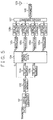
- Fig. 5 is a block diagram showing the structure of a transmitting section of a first embodiment of a spread spectrum diversity transmitter/receiver of the present invention.
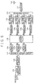
- Fig. 6 is a block diagram showing the structure of a receiving section of a first embodiment of a spread spectrum diversity transmitter/receiver of the present invention.
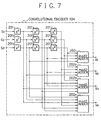
- Fig. 7 is a block diagram showing the structure of a convolutional encoder in Fig. 5.
- the elements of the same sign numbers as those in Figs. 3 and 4 have the same functions.
- the number of diversity branches M 4
- M pieces of interleave circuit 102 1 to 102 M in Fig. 3 are replaced by one interleave circuit 102 and this interleave circuit 102 is disposed between the error correction encoder 101 and the delay elements 103 1 and 103 2 , and the convolutional encoder 104 is added in front of the modulators 105 1 to 105 4 .
- An output signal from the interleave circuit 102 and output signals from the delay elements 103 1 and 103 2 are inputted to the convolutional encoder 104 as parallel data S1, S2 and S3 respectively.
- the convolutional encoder 104 outputs parallel data V1, V2, V3 and V4 after the inputted signals are encoded by the convolutional encoding.
- the convolutional encoder 104 is constituted of nine flip flop (FF) circuits 201 1 to 201 9 and four mod2 adders 202 1 to 202 4 .
- FF flip flop
- the FF circuits 201 1 to 201 9 correspond to X 0 , X 1 , X 2 , ..., X 8 and memorize the parallel data inputs S 1 , S 2 and S 3 by a predetermined connection in sequence.
- the mod2 adders 202 1 to 202 4 perform an addition in the binary system (modulus 2 addition) for predetermined signals in the output signals of the FF circuits 201 1 to 201 9 .
- X n means the " n " th power of X.
- the generating multinomial of V 1 is shown in the equation (1).
- the output of the V 1 is that the outputs of the FF circuits 201 3 , 201 6 , 201 8 and 201 9 corresponding to X 2 , X 5 , X 7 and X 8 are operated by the mod2 addition (Exclusive OR) at the mod2 adder 202 1 .
- the outputs are that the outputs of the corresponding FF circuits shown in the generating multinomials (2) to (4) are operated by the mod2 addition at the corresponding mod2 adder.
- the number of diversity branches M 4
- M pieces of deinterleave circuit 118 1 to 118 M in Fig. 4 are replaced by one deinterleave circuit 118 and this deinterleave circuit 118 is disposed between the majority judging circuit 117 and the error correction decoder 119, and the Viterbi decoder 115 is added in front of the delay elements 116 1 to 116 3 .
- an error correction encoding is performed for transmitting data at the error correction encoder 101 and the interleave circuit 102.
- This error correction encoding corrects a burst error.
- the output signal of the interleave circuit 102 is made to branch in three signals and the signals of a second branch and a third branch are given delay time by the delay elements 103 1 and 103 2 . This means that the time diversity is performed and the same effect explained at the conventional example can be obtained.
- a feature of the first embodiment of the present invention is that a convolutional encoding is performed, as these plural branch signals are made to be parallel input data.
- the convolutional encoder 104 whose coding rate R is 3/4 is shown as an example, and whose circuit is shown in Fig. 7.
- the spread spectrum is performed for modulated waves outputted from the modulators 105 1 to 105 4 at the spread spectrum circuits 106 1 to 106 4 by respective independent random series.
- the code division multiplex is performed for diversity transmitting signals of four branches.
- the frequency conversion and the amplification are applied at the transmitter 108 for the code division multiplex signal performed at the combining circuit 107, and the signal is supplied to the transmitting antenna 109 and transmitted as a radio transmitting wave.
- the error correction is performed before the transmitting data are made to branch in plural branches, and the code division multiplex is simply applied for the diversity branch signals and the result signal is transmitted.
- an error correction means named the convolutional encoding is added to the diversity branches themselves, therefore the number of branches from the convolutional encoder increases but a stronger error correction function is installed.
- the error correction system proposed at the present invention is named an error correction among diversity branches.
- the frequency conversion from the radio frequency band to the spread spectrum signal band at the receiver 111 is applied for the wave received at the receiving antenna 110 and the converted signal is made to branch in four branches at the branching circuit 112.
- the de-spread spectrum that is, the separation of code division multiplex waves is applied for the signals of the four branches at the four de-spread spectrum circuits 113 1 to 113 4 .
- the demodulation corresponding to the primary modulation applied at the transmitting section is applied for the four branch signals outputted from the de-spread spectrum circuits 113 1 to 113 4 at the demodulators 114 1 to 114 4 .
- the four branch demodulated signals are inputted to the Viterbi decoder 115 as parallel data series W 1 to W 4 .
- the error correction by the convolutional coding at the transmitting section is performed and the bit errors occurred at the transmission channel are corrected.
- the decoded data series are outputted as Y 1 , Y 2 and Y 3 , and are inputted to the three delay elements 116 1 to 116 3 .
- the delay difference for the time diversity given at the delay elements 103 1 and 103 2 in the transmitting section is absorbed. That is, the timing of each branch at the outputs of the three delay elements 116 1 to 116 3 in the receiving section becomes the same and the majority judgment at the majority judging circuit 117 becomes possible.
- the inverse operation of the interleave operation at the transmitting section is applied at the deinterleave circuit 118 to the branch signals judged at the majority judging circuit 117, and the order of the data series is changed to the right order.
- the output signals of the deinterleave circuit 118 are inputted to the error correction decoder 119, and the error correction corresponding to the error correction at the error correction encoder 101 at the transmitting section is applied to the output signal from the deinterleave circuit 118 and the result is outputted as the received data.
- the majority judging circuit 117 in the conventional spread spectrum diversity transmitter/receiver the majority is divided into two parts and at the case that it can not be decided which one is the right judgment, the probability that the bit error occurs is high.
- the second error correction means before the majority judgment the majority or minority can be made clear at the majority judgment and the bit error can be suppressed.
- the plural pieces of interleave circuit and the plural pieces of deinterleave circuits are needed corresponding to the diversity branches, however at the first embodiment of the present invention, the interleave operation is moved to the outside of the diversity branches. Therefore it is enough that only one interleave circuit and one deinterleave circuit are installed.
- the convolutional encoder 104 and the Viterbi decoder 115 can be made in LSI and are small in size. Therefore, the increase of the size of the apparatus by installing the convolutiona encoder 104 and the Viterbi decoder 115 is not large. The effect of the reduction of the interleave circuits and the deinterleave cirsuits is larger.
- the coding rate R is set as 3/4, however generally the coding rate R can be set as N/M.
- the output signal from the interleave circuit 102 in Fig. 5 is made to branch N branches and M pieces of parallel output from the convolutional encoder 104 are made to the diversity branches.
- the M pieces of the modulator 105 and the M pieces of the spread spectrum circuit 106 have to be provided.
- Fig. 8 is a block diagram showing the structure of the transmitting section of a second embodiment of the spread spectrum diversity transmitter/receiver of the present invention.
- Fig. 9 is a block diagram showing the structure of the receiving section of a second embodiment of the spread spectrum diversity transmitter/receiver of the present invention.
- the error correction encoder 101 and the interleave circuit 102 are deleted.
- the error correction decoder 119 and the deinterleave circuit 118 are deleted.
- the deletion of the error correction encoder and the error correction decoder is described in Japanese Patent Application Laid-Open No. HEI 8-191289.
- the reason is mentioned as the majority judging circuit has the almost the same effect of the error correction.
- the bit error is suppressed to as small as possible by using the error correction means among the branches by utilizing the convolutional encoding, and further by using with the majority judging circuit 117, the bit error rate is improved. Therefore, even though the error correction encoder 101 and the interleave circuit 102 are deleted from the first embodiment, the high channel quality can be obtained.
- an error correction additional bit is not needed, due to that the error correction function is deleted. Consequently, the signal band can be reduced, the frequency efficiency becomes high comparing with the first embodiment of the present invention.
- the present invention has the following effects.
- the diversity branches are utilized for not only the diversity branches but also for the error correction means, therefore the bit error rate can be improved.
- the interleave circuit at the transmitting section and the deinterleave circuit at the receiving section can be made to be one each, without any relation with the number of respective branches, therefore the size of the apparatus can be made to be small.
Landscapes
- Engineering & Computer Science (AREA)
- Computer Networks & Wireless Communication (AREA)
- Signal Processing (AREA)
- Artificial Intelligence (AREA)
- Radio Transmission System (AREA)
- Error Detection And Correction (AREA)
- Detection And Prevention Of Errors In Transmission (AREA)
Abstract
Description
- The present invention relates to a spread spectrum diversity transmitter/receiver that performs code division multiple access communication by a spread spectrum technology at a digital radio transmission that has a severe multi path fading problem in particular.
- At a radio transmission by a fading channel, generally a diversity reception is needed. As fading, there are a flat fading and a selective fading. At the flat fading, a multi path propagation is not generated, but an amplitude/phase of a receiving wave itself is directly varied during the propagation. At the selective fading, the multi path propagation is generated, and an amplitude/phase of arrival waves by each multi path is independently varied. In this case, since the received signal becomes a combined wave of plural multi path waves, depending on a state of the phase shift, the received signal may become an inverse phase combination at a frequency. That is, a frequency selective fade (notch) occurs in a received spectrum. At the flat fading, a variation of a received level is a problem and the received waveform itself is not distorted. However, at the selective fading by the multi path, in addition to the variation of the received level, a distortion of the waveform occurs.
- For the fading channel mentioned above, a diversity reception and an adaptive equalizing technology have been conventionally applied. There are several conventional technologies, however in this, as a conventional technology, a spread spectrum communication, which is said to be effective against the multi path distortion, is mentioned. The object of the spread spectrum technology is originally developed for military communication being robust against jamming wave. The multi path wave whose delay time is long has a low correlation with a desiring main wave signal. At the case that the spread spectrum technology is applied, the correlation between the multi path wave and a spread code can not be established and the multi path wave is suppressed at de-spread operation. That is, at the spread spectrum technology, the multi path wave is regarded as interference, therefore the spread spectrum technology is a kind of adaptive equalizer.
- However, the multi path wave whose delay time is short has a high correlation with a main wave signal, therefore the suppression by the de-spread operation can not be expected. In this case, since the delay time between the multi path wave and the main wave is short, at the time when the relation between the multi path wave and the main wave becomes an inverse phase, a decline of level, that is, a fade out can be generated. In order to cope with this kind of fade out, a diversity reception utilized non-correlation among plural propagation paths becomes indispensable.
- Fig. 1 is a diagram showing the structure of a diversity reception. Referring to Fig. 1, the diversity reception is explained. In Fig. 1, the transmission is performed from a transmitter 401 to a receiver 402, radio waves transmitted from the transmitter 401 arrive the receiver 402 via three different paths 403, 404 and 405.
- In this, it is assumed that the transmitter 401 transmits the radio waves by using one non-directional antenna. The radio waves emitted from the non-directional antenna are propagated through the path 404 being a direct propagation path, and the paths 403 and 405 through which reflected waves are propagated. By the radio waves emitted from the non-directional antenna are propagated through the different paths, therefore multi path propagation occurs. Figs. 2A, 2B and 2C are diagrams showing the variation of a received electric field level at each path. In this case, the paths are different in space, the fading generated at each path is independent, and the variations of the received electric field level in the passage of time are shown in Figs. 2A, 2B and 2C.
- In Fig. 2A, the variation of a received electric field level at the path 403 is shown, in Fig. 2B, the variation of a received electric field level at the path 404 is shown and in Fig. 2C, the variation of a received electric field level at the path 405 is shown.
- For this kind of propagation, the diversity reception selects or combines the parts not faded out in each diversity branch and makes the probability of fading out decrease. This kind of diversity reception is named as a space diversity or a path diversity because of utilizing the non-correlation among the propagation paths. As a means to realize this diversity, generally an adaptive array using plural antennas is applied. That is, by extracting plural multi path arriving waves using a directional control of the adaptive array, and combining the maximum ratio, a diversity combination can be performed.
- However, at the space diversity, plural antennas are needed, therefore a disadvantage at cost occurs. In particular, at microwave communication, the cost of antenna is high and the apparatus becomes large, therefore the number of antennas can not be increased without careful consideration.
- In order to improve the problem of this space diversity, Japanese Patent Application Laid-Open No. HEI 8-191289 discloses a spread spectrum diversity transmitter/receiver that utilizes a code division multiplex and a time diversity by a spread spectrum. This conventional spread spectrum diversity transmitter/receiver is shown in Figs. 3 and 4.
- Fig. 3 is a block diagram showing the structure of a transmitting section of this conventional spread spectrum diversity transmitter/receiver, and Fig. 4 is a block diagram showing the structure of a receiving section of this conventional spread spectrum diversity transmitter/receiver.
- As shown in Fig. 3, the transmitting section of this conventional spread spectrum diversity transmitter/receiver provides an error correction encoder 101, M-1 pieces of delay element whose delay time is τ M 1031 to 103M-1, M pieces of interleave circuit 1021 to 102M, M pieces of modulator 1051 to 105M, M pieces of spread spectrum circuit 1061 to 106M, a combining circuit 107, a transmitter 108 and a transmitting antenna 109.
- The error correction encoder 101 performs an error correction encoding for one series of transmitting data.
- The delay elements 1031 to 103M-1, by giving delay time of τ M to an output of the error correction encoder 101 respectively, makes the output of the error correction encoder 101 branch to M ― 1 pieces.
- The interleave circuits 1021 to 102M perform interleave respectively for the output from the error correction encoder 101 and the outputs from the delay elements 1031 to 103M-1.
- The modulators 1051 to 105M modulate the outputs from the interleave circuits 1021 to 102M.
- The spread spectrum circuits 1061 to 106M perform a spread spectrum operation to the outputs from the modulators 1051 to 105M by different spread codes.
- The combining circuit 107 combines the outputs from the spread spectrum circuits 1061 to 106M and performs code division multiplex for them and outputs the result.
- The transmitter 108 transmits the code division multiplex signal outputted from the combining circuit 107, through the transmitting antenna 109.
- As shown in Fig. 4, the receiving section of this conventional spread spectrum diversity transmitter/receiver provides a receiving antenna 110, a receiver 111, a branching circuit 112, M pieces of de-spread spectrum circuit 1131 to 113M, M pieces of demodulator 1141 to 114M, M pieces of deinterleave circuit 1181 to 118M, M pieces of delay element whose delay time is η N 1161 to 116M, a majority judging circuit 117 and an error correction decoder 119.
- The receiver 111 receives the code division multiplex signal transmitted from the transmitting section shown in Fig. 3, through the receiving antenna 110.
- The branching circuit 112 makes the signal received at the receiver 111 branch to M pieces and outputs as M branch signals.
- The de-spread spectrum circuits 1131 to 113M perform de-spread spectrum operation to the M branch signals outputted from the branching circuit 112 by using the same spread codes used at the time of the spread at the transmitting section.
- The demodulators 1141 to 114M demodulate each received signal of the M branch signals performed the de-spread at the de-spread spectrum circuits 1131 to 113M.
- The deinterleave circuits 1181 to 118M perform deinterleave respectively for the signals demodulated at the demodulators 1141 to 114M.
- The delay elements 1161 to 116M give delay time of η N to each output from the deinterleave circuits 1181 to 118M. In this, the reason why the delay time is given, the delay difference applied to the transmitting section is eliminated and the signal timing of each branch is made to match.
- The majority judging circuit 117 performs a majority judgment for each branch signal outputted from the delay elements 1161 to 116M.
- The error correction decoder 119 performs an error correction decoding corresponding to the error correction encoder 101 at the transmitting section for the signals outputted from the majority judging circuit 117 and outputs the result as a received signal.
- Next, referring to Figs. 3 and 4, the operation of the conventional spread spectrum diversity transmitter/receiver is explained.
- At the transmitting section in Fig. 3, after an error correction is applied to the transmitting data by the error correction encoder 101, this data is made to branch to multi branch of M pieces. And a delay difference is given among branches by the delay elements 1031 to 103M-1, and each branch is used as a time diversity. At the interleave circuits 1021 to 102M, an independent interleave is applied to each branch. After this, at the modulators 1051 to 105M, a modulation is applied to each data. Further, at the spread spectrum circuits 1061 to 106M, a spread spectrum is applied to each data, and at the combining circuit 107, transmitting signals of each branch are combined. In this, each branch is a signal in the same frequency band and the combined signal becomes a code division multiplex signal. The output signal of the combining circuit 107 is converted to a signal of the radio frequency band at the transmitter 108 and transmitted from the transmitting antenna 109.
- At the receiving section in Fig. 4, a received signal at the receiving antenna 110 is converted from a signal of the radio frequency band to a signal of the frequency band of the spread spectrum at the receiver 111 and the converted signal is made to branch to M branches at the branching circuit 112. The received signals of M branches made to branch at the branching circuit 112 are inputted to the M pieces of the de-spread spectrum circuit 1131 to 113M corresponding to the transmission section and the de-spread spectrum is applied to the signals. In this operation, the received signals of code division multiplex are extracted every corresponding branches. The extracted received signals are inputted to the M pieces of demodulator 1141 to 114M, and after this are inputted to the M pieces of deinterleave circuit 1181 to 118M and the deinterleave operation is applied. The delay difference applied at the transmitting section is eliminated from the M branch received signals at the delay elements 1161 to 116M, and the signal timing of each branch is matched. The majority judgment is performed for the outputs of the received signals at the majority judging circuit 117, and further the error correction decoding is applied to the outputted signals, at the error correction decoder 119.
- At the conventional example in Figs. 3 and 4, not only a burst error caused by the multi fading is simply made to randomize by the interleave, but the time diversity is applied by the delay difference operation, with this operation, the channel quality against fading is improved. The combining means in the time diversity, for digital signals, finally depends on a switching means. At the conventional example, by applying the majority judgment, more likelihood judgment is performed and the transmission quality is improved.
- However, at this conventional example, the combination of the diversity branches is performed by the majority judgment of each branch. For example, at the case that the number of branches is 10 and the three branches show digital signal " 1 " and the remaining seven branches show digital signal " 0 ", the majority judging circuit 117 judges " 0 ". However, at the case that the branches showing " 1 " are five and the branches showing " 0 " are five, there is a problem that the majority judging circuit 117 can not distinct which judgment is correct. Moreover, since the error probability of each branch is random, in spite of " 1 " is a right signal, there is a possibility that the greater part of the branches are judged as " 0 ". At this case, the majority judging circuit 117 simply judges " 0 " and output the result. Therefore, at the conventional spread spectrum diversity transmitter/receiver, there is a possibility that an error occurs at the majority judgment, and the characteristic of the bit error rate is deteriorated.
- Moreover, at this conventional example, the interleave circuits 1021 to 102M and the deinterleave circuits 1181 to 118M are needed at each diversity branch, therefore there is a problem that the size of the apparatus becomes large.
- Consequently, at the mentioned above conventional spread spectrum diversity transmitter/receiver, there are following problems:
- 1 ) there is a possibility that an error occurs at the majority judgment, at this case that a bit error rate is deteriorated,
- 2 ) plural interleave circuits and plural deinterleave circuits are needed at diversity branches, therefore the size of the apparatus becomes large.
-
- It is therefore an object of the present invention to provide a spread spectrum diversity transmitter/receiver whose size is small and in which the characteristic of the bit error rate is improved.
- According to the present invention, for achieving the objects, a spread spectrum diversity transmitter/receiver provides a spread spectrum diversity transmitter and a spread spectrum diversity receiver. And said spread spectrum diversity transmitter includes an error correction encoding means for performing an error correction encoding for a series of transmitting data, an interleave means for performing an interleave for a signal outputted from said error correction encoding means, plural delay means which give different delay time for the signal outputted from said interleave means and makes said signal branch to N - 1 branches, a convolutional encoding means which performs a convolutional encoding whose coding rate
- According to the present invention, at a spread spectrum diversity transmitter/receiver of the present invention, a burst error generated by a short break caused by a multi path fading is corrected by an error correction and an interleave. In addition to this, a diversity transmission and reception is performed by reducing the time correlation among branches by giving delay difference operation, and a convolutional encoding is performed among branches. With this, at the present invention, multi dimensional transmitting signal by code division is utilized not only for diversity itself but also for error correction means. Moreover, by operating a majority judgment that selects a majority among branches, plural diversity branch signals are converted to the most likelihood one series data and a bit error is equivalently corrected. At the spread spectrum diversity receiver, an error correction decoding corresponding to the error correction encoding at the spread spectrum diversity transmitter is performed and the channel quality is improved.
- Therefore, at a spread spectrum communication, without using a space diversity or a frequency diversity by installing fixed plural antennas or adaptive arrays, a diversity reception by code division multiplex becomes possible. Therefore, a bit error rate can be improved. And without any relation with the number of branches, it is enough that the number of the interleave circuit and the deinterleave circuit is one each, consequently the size of the apparatus can be reduced.
- At another spread spectrum diversity transmitter/receiver of the present invention, an error correction encoding means and an interleave means are deleted from the mentioned above spread spectrum diversity transmitter, and an error correction decoding means and a deinterleave means are deleted from the mentioned above spread spectrum diversity receiver.
- At this another spread spectrum diversity transmitter/receiver, only the effect of bit error corrections by the convolutional encoding among branches and the majority judgment is utilized, and the error correction functions and the interleave function are deleted. With this, an error correction additional bit becomes unnecessary due to that the error correction functions are deleted, the signal band can be reduced and the frequency efficiency can be improved.
- The objects and features of the present invention will become more apparent from the consideration of the following detailed description taken in conjunction with the accompanying drawings in which:
- Fig. 1 is a diagram showing the structure of a diversity reception;
- Fig. 2A is a diagram showing the variation of a received electric field level at a path 403 in Fig. 1;
- Fig. 2B is a diagram showing the variation of a received electric field level at a path 404 in Fig. 1;
- Fig. 2C is a diagram showing the variation of a received electric field level at a path 405 in Fig. 1;
- Fig. 3 is a block diagram showing the structure of a transmitting section of a conventional spread spectrum diversity transmitter/receiver;
- Fig. 4 is a block diagram showing the structure of a receiving section of the conventional spread spectrum diversity transmitter/receiver;
- Fig. 5 is a block diagram showing the structure of a transmitting section of a first embodiment of a spread spectrum diversity transmitter/receiver of the present invention;
- Fig. 6 is a block diagram showing the structure of a receiving section of the first embodiment of the spread spectrum diversity transmitter/receiver of the present invention;
- Fig. 7 is a block diagram showing the structure of a convolutional encoder in Fig. 5;
- Fig. 8 is a block diagram showing the structure of a transmitting section of a second embodiment of a spread spectrum diversity transmitter/receiver of the present invention; and
- Fig. 9 is a block diagram showing the structure of a receiving section of the second embodiment of the spread spectrum diversity transmitter/receiver of the present invention.
-
- Referring now to the drawings, embodiments of the present invention are explained in detail.
- Fig. 5 is a block diagram showing the structure of a transmitting section of a first embodiment of a spread spectrum diversity transmitter/receiver of the present invention. Fig. 6 is a block diagram showing the structure of a receiving section of a first embodiment of a spread spectrum diversity transmitter/receiver of the present invention. And Fig. 7 is a block diagram showing the structure of a convolutional encoder in Fig. 5. In Figs. 5 and 6, the elements of the same sign numbers as those in Figs. 3 and 4 have the same functions.
- As shown in Fig. 5, the transmitting section of the first embodiment of the spread spectrum diversity transmitter/receiver of the present invention is constituted of an error correction encoder 101, an interleave circuit 102, two delay elements 1031 and 1032 whose delay time is different each other, a convolutional encoder 104 whose coding rate R = 3/4, four pieces of modulator 1051 to 1054, four pieces of spread spectrum circuit 1061 to 1064, a combining circuit 107, a transmitter 108 and a transmitting antenna 109.
- Comparing with the transmitting section of the conventional spread spectrum diversity transmitter/receiver shown in Fig. 3, at the transmitting section of the first embodiment of the present invention, the number of diversity branches M = 4, and M pieces of interleave circuit 1021 to 102M in Fig. 3 are replaced by one interleave circuit 102 and this interleave circuit 102 is disposed between the error correction encoder 101 and the delay elements 1031 and 1032, and the convolutional encoder 104 is added in front of the modulators 1051 to 1054.
- An output signal from the interleave circuit 102 and output signals from the delay elements 1031 and 1032 are inputted to the convolutional encoder 104 as parallel data S1, S2 and S3 respectively. And the convolutional encoder 104 outputs parallel data V1, V2, V3 and V4 after the inputted signals are encoded by the convolutional encoding.
- As shown in Fig. 7, the convolutional encoder 104 is constituted of nine flip flop (FF) circuits 2011 to 2019 and four mod2 adders 2021 to 2024.
- The FF circuits 2011 to 2019 correspond to X0, X1, X2, ..., X8 and memorize the parallel data inputs S1, S2 and S3 by a predetermined connection in sequence.
- The mod2 adders 2021 to 2024 perform an addition in the binary system (modulus 2 addition) for predetermined signals in the output signals of the FF circuits 2011 to 2019.
- At the mod2 addition, the following operation is performed.
- The convolutional encoder 104 shown in Fig. 7 is a case that the constraint length K = 9, generally the encoding is performed by the following generating multinomials:
- In these multinomials (1) to (4), Xn means the " n " th power of X. In Fig. 7, for example, the generating multinomial of V1 is shown in the equation (1). The output of the V1 is that the outputs of the FF circuits 2013, 2016, 2018 and 2019 corresponding to X2, X5, X7 and X8 are operated by the mod2 addition (Exclusive OR) at the mod2 adder 2021. At the V2, V3 and V4, the outputs are that the outputs of the corresponding FF circuits shown in the generating multinomials (2) to (4) are operated by the mod2 addition at the corresponding mod2 adder.
- As shown in Fig. 6, the receiving section of the first embodiment of the spread spectrum diversity transmitter/receiver of the present invention is constituted of a receiving antenna 110, a receiver 111, a branching circuit 112, four de-spread spectrum circuits 1131 to 1134, four demodulators 1141 to 1144, a Viterbi decoder 115 whose coding rate R = 3/4, three delay elements 1161 to 1163, a majority judging circuit 117, a deinterleave circuit 118 and an error correction decoder 119.
- Comparing with the receiving section of the conventional spread spectrum diversity transmitter/receiver shown in Fig. 4, at the receiving section of the first embodiment of the present invention, the number of diversity branches M = 4, and M pieces of deinterleave circuit 1181 to 118M in Fig. 4 are replaced by one deinterleave circuit 118 and this deinterleave circuit 118 is disposed between the majority judging circuit 117 and the error correction decoder 119, and the Viterbi decoder 115 is added in front of the delay elements 1161 to 1163.
- The received signals of M branches demodulated at the demodulators 1141 to 1144 are inputted to the Viterbi decoder 115 as parallel input data W1 to W4, and the Viterbi decoder 115 performs the Viterbi decoding of the coding rate R = 3/4 and outputs the result as parallel output data Y1 to Y3.
- Next, referring to Figs. 5, 6 and 7, the operation of the first embodiment of the present invention is explained.
- First, at the transmitting section, an error correction encoding is performed for transmitting data at the error correction encoder 101 and the interleave circuit 102. This error correction encoding corrects a burst error. And the output signal of the interleave circuit 102 is made to branch in three signals and the signals of a second branch and a third branch are given delay time by the delay elements 1031 and 1032. This means that the time diversity is performed and the same effect explained at the conventional example can be obtained. A feature of the first embodiment of the present invention is that a convolutional encoding is performed, as these plural branch signals are made to be parallel input data. The convolutional encoder 104 whose coding rate R is 3/4 is shown as an example, and whose circuit is shown in Fig. 7.
- At the convolutional encoding by the convolutional encoder 104 whose coding rate R = 3/4, three lines input data series S1 to S3 are outputted as four lines data series V1 to V4. And the output signals from the convolutional encoder 104 are primarily modulated at the four modulators 1051 to 1054 respectively. The spread spectrum is performed for modulated waves outputted from the modulators 1051 to 1054 at the spread spectrum circuits 1061 to 1064 by respective independent random series. By combining the output signals from the four spread spectrum circuits 1061 to 1064 at the combining circuit 107, the code division multiplex is performed for diversity transmitting signals of four branches. And the frequency conversion and the amplification are applied at the transmitter 108 for the code division multiplex signal performed at the combining circuit 107, and the signal is supplied to the transmitting antenna 109 and transmitted as a radio transmitting wave.
- At the conventional example, the error correction is performed before the transmitting data are made to branch in plural branches, and the code division multiplex is simply applied for the diversity branch signals and the result signal is transmitted. At the present invention, an error correction means named the convolutional encoding is added to the diversity branches themselves, therefore the number of branches from the convolutional encoder increases but a stronger error correction function is installed. Especially the error correction system proposed at the present invention is named an error correction among diversity branches.
- At the receiving section of the first embodiment of the present invention, the frequency conversion from the radio frequency band to the spread spectrum signal band at the receiver 111 is applied for the wave received at the receiving antenna 110 and the converted signal is made to branch in four branches at the branching circuit 112. The de-spread spectrum, that is, the separation of code division multiplex waves is applied for the signals of the four branches at the four de-spread spectrum circuits 1131 to 1134. The demodulation corresponding to the primary modulation applied at the transmitting section is applied for the four branch signals outputted from the de-spread spectrum circuits 1131 to 1134 at the demodulators 1141 to 1144. The four branch demodulated signals are inputted to the Viterbi decoder 115 as parallel data series W1 to W4. These parallel data series W1 to W4 correspond to the parallel data series V1, V2, V3 and V4 coded at the transmitting section and are applied the decoding of the coding rate R = 3/4 at the Viterbi decoder 115. At this, the error correction by the convolutional coding at the transmitting section is performed and the bit errors occurred at the transmission channel are corrected. The decoded data series are outputted as Y1, Y2 and Y3, and are inputted to the three delay elements 1161 to 1163. At this, the delay difference for the time diversity given at the delay elements 1031 and 1032 in the transmitting section is absorbed. That is, the timing of each branch at the outputs of the three delay elements 1161 to 1163 in the receiving section becomes the same and the majority judgment at the majority judging circuit 117 becomes possible. The inverse operation of the interleave operation at the transmitting section is applied at the deinterleave circuit 118 to the branch signals judged at the majority judging circuit 117, and the order of the data series is changed to the right order. The output signals of the deinterleave circuit 118 are inputted to the error correction decoder 119, and the error correction corresponding to the error correction at the error correction encoder 101 at the transmitting section is applied to the output signal from the deinterleave circuit 118 and the result is outputted as the received data.
- As mentioned above, at the first embodiment of the present invention, as a second error correction means among diversity branches, the convolutional encoding whose coding rate R = 3/4 is applied to the diversity signals of three branches. Therefore, the diversity branches are utilized not only for the only diversity but also for the error correction means, consequently the bit error rate can be improved at the front stage of the majority judging circuit 117.
- Therefore, at the majority judging circuit 117 in the conventional spread spectrum diversity transmitter/receiver, the majority is divided into two parts and at the case that it can not be decided which one is the right judgment, the probability that the bit error occurs is high. However, at the first embodiment of the present invention, by applying the second error correction means before the majority judgment, the majority or minority can be made clear at the majority judgment and the bit error can be suppressed.
- Moreover, at the conventional example, the plural pieces of interleave circuit and the plural pieces of deinterleave circuits are needed corresponding to the diversity branches, however at the first embodiment of the present invention, the interleave operation is moved to the outside of the diversity branches. Therefore it is enough that only one interleave circuit and one deinterleave circuit are installed. The convolutional encoder 104 and the Viterbi decoder 115 can be made in LSI and are small in size. Therefore, the increase of the size of the apparatus by installing the convolutiona encoder 104 and the Viterbi decoder 115 is not large. The effect of the reduction of the interleave circuits and the deinterleave cirsuits is larger.
- In the embodiment mentioned above, the coding rate R is set as 3/4, however generally the coding rate R can be set as N/M. In this case, the output signal from the interleave circuit 102 in Fig. 5 is made to branch N branches and M pieces of parallel output from the convolutional encoder 104 are made to the diversity branches. However, in this case, the M pieces of the modulator 105 and the M pieces of the spread spectrum circuit 106 have to be provided.
- Next, a second embodiment of the spread spectrum diversity transmitter/receiver of the present invention is explained.
- Fig. 8 is a block diagram showing the structure of the transmitting section of a second embodiment of the spread spectrum diversity transmitter/receiver of the present invention. Fig. 9 is a block diagram showing the structure of the receiving section of a second embodiment of the spread spectrum diversity transmitter/receiver of the present invention.
- As shown in Fig. 8, a transmitting section of the second embodiment of the spread spectrum diversity transmitter/receiver of the present invention provides two delay elements 1031 and 1032, a convolutional encoder 104 whose coding rate R = 3/4, four modulators 1051 to 1054, four spread spectrum circuits 1061 to 1064, a combining circuit 107, a transmitter 108 and a transmitting antenna 109.
- As shown in Fig. 9, a receiving section of the second embodiment of the spread spectrum diversity transmitter/receiver of the present invention provides a receiving antenna 110, a receiver 111, a branching circuit 112, four de-spread spectrum circuits 1131 to 1134, four demodulators 1141 to 1144, a Viterbi decoder 115 whose coding rate R = 3/4, three delay elements 1161 and 1163, and a majority judging circuit 117.
- At the transmitting section of the second embodiment of the spread spectrum diversity transmitter/receiver of the present invention, comparing with that of the first embodiment shown in Fig. 5, the error correction encoder 101 and the interleave circuit 102 are deleted.
- At the receiving section of the second embodiment of the spread spectrum diversity transmitter/receiver of the present invention, comparing with that of the first embodiment shown in Fig. 6, the error correction decoder 119 and the deinterleave circuit 118 are deleted.
- The deletion of the error correction encoder and the error correction decoder is described in Japanese Patent Application Laid-Open No. HEI 8-191289. The reason is mentioned as the majority judging circuit has the almost the same effect of the error correction. However, at the second embodiment of the present invention, the bit error is suppressed to as small as possible by using the error correction means among the branches by utilizing the convolutional encoding, and further by using with the majority judging circuit 117, the bit error rate is improved. Therefore, even though the error correction encoder 101 and the interleave circuit 102 are deleted from the first embodiment, the high channel quality can be obtained.
- At the second embodiment of the present invention, an error correction additional bit is not needed, due to that the error correction function is deleted. Consequently, the signal band can be reduced, the frequency efficiency becomes high comparing with the first embodiment of the present invention.
- As mentioned above, the present invention has the following effects. By newly adding the error correction means by the convolutional encoding for the diversity signals of N branches, the diversity branches are utilized for not only the diversity branches but also for the error correction means, therefore the bit error rate can be improved.
- The interleave circuit at the transmitting section and the deinterleave circuit at the receiving section can be made to be one each, without any relation with the number of respective branches, therefore the size of the apparatus can be made to be small.
- While the present invention has been described with reference to the particular illustrative embodiments, it is not to be restricted by those embodiments but only by the appended claims. It is to be appreciated that those skilled in the art can change or modify the embodiments without departing from the scope and spirit of the present invention.
Claims (6)
- A spread spectrum diversity transmitter, comprising:an error correction encoding means (101) for performing an error correction encoding for a series of transmitting data;an interleave means (102) for performing an interleave for a signal outputted from said error correction encoding means (101);plural delay means (1031,1032) which give different delay time for the signal outputted from said interleave means (102) and makes said signal branch to N - 1 branches;a convolutional encoding means (104) which performs a convolutional encoding whose coding rateplural modulating means (1051-1054) for modulating said signals of parallel data of M branches outputted from said convolutional encoding means (104) respectively;plural spread spectrum means (1061-1064) for performing spread spectrums for signals outputted from said plural modulating means (1051-1054) by respective different spread codes;a combining means (107) for performing a code division multiplex by combining said outputs from said plural spread spectrum means (1061-1064); anda transmitting means (108) for transmitting said code division multiplex signal.
- A spread spectrum diversity receiver, comprising:a receiving means (111) for receiving a code division multiplex signal transmitted from a spread spectrum diversity transmitter;a branching means (112) for making said signal received at said receiving means (111) branch to M branches and outputs M branch signals;plural de-spread spectrum means (1131-1134) for performing de-spread spectrums for said M branch signals by using the same spread codes used at the time when the spread was performed at the spread spectrum diversity transmitter;plural demodulating means (1141-1144) for demodulating said M branch signals performed the de-spread at said plural de-spread spectrum means (1131-1134);a Viterbi decoding means (115) to which said demodulated M branch signals are inputted as parallel data and performs a Viterbi decoding whose coding rateplural delay means (1161-1163) which give different delay time for each branch of parallel data of N branches outputted from said Viterbi decoding means (115) and adjusts each delay;a majority judging means (117) which performs a majority judgement for each branch signal outputted from said delay means (1161-1163)and outputs the judged data;a deinterleave means (118) for performing a deinterleave for said judged data at said majority judging means (117); andan error correction decoding means (119) for performing an error correction decoding corresponding to an error correction encoding means (101) of the spread spectrum diversity transmitter for the data outputted from said deinterleave means (118).
- A spread spectrum diversity transmitter/receiver, comprising:a spread spectrum diversity transmitter, anda spread spectrum diversity receiver,said spread spectrum diversity transmitter, including:an error correction encoding means (101) for performing an error correction encoding for a series of transmitting data;an interleave means (102) for performing an interleave for a signal outputted from said error correction encoding means (101);plural delay means (1031,1032) which give different delay time for the signal outputted from said interleave means (102) and makes said signal branch to N - 1 branches;a convolutional encoding means (104) which performs a convolutional encoding whose coding rateplural modulating means (1051-1054) for modulating said signals of parallel data of M branches outputted from said convolutional encoding means (104) respectively;plural spread spectrum means (1061-1064) for performing spread spectrums for signals outputted from said plural modulating means (1051-1054) by respective different spread codes;a combining means (107) for performing a code division multiplex by combining said outputs from said plural spread spectrum means (1061-1064); anda transmitting means (108) for transmitting said code division multiplex signal,and said spread spectrum diversity receiver, including:a receiving means (111) for receiving said code division multiplex signal transmitted from said spread spectrum diversity transmitter;a branching means (112) for making said signal received at said receiving means (111) branch to M branches and outputs M branch signals;plural de-spread spectrum means (1131-1134) for performing de-spread spectrums for said M branch signals by using the same spread codes used at the time when the spread was performed at said spread spectrum diversity transmitter;plural demodulating means (1141-1144) for demodulating said M branch signals performed the de-spread at said plural de-spread spectrum means (1131-1134);a Viterbi decoding means (115) to which said demodulated M branch signals are inputted as parallel data and performs a Viterbi decoding whose coding rateplural delay means (1161-1163) which give different delay time for each branch of parallel data of N branches outputted from said Viterbi decoding means (115) and adjusts each delay;a majority judging means (117) which performs a majority judgment for each branch signal outputted from said delay means (1161-1163) and outputs the judged data;a deinterleave means (118) for performing a deinterleave for said judged data at said majority judging means (117); andan error correction decoding means (119) for performing an error correction decoding corresponding to said error correction encoding means (101) of said spread spectrum diversity transmitter for the data outputted from said deinterleave means (118).
- A spread spectrum diversity transmitter, comprising:plural delay means (1031,1032) which give different delay time for a series of transmitting data and makes said transmitting data branch to N - 1 branches;a convolutional encoding means (104) which performs a convolutional encoding whose coding rateplural modulating means (1051-1054) for modulating said signals of parallel data of M branches outputted from said convolutional encoding means (104) respectively;plural spread spectrum means (1061-1064) for performing spread spectrums for signals outputted from said plural modulating means (1051-1054) by respective different spread codes;a combining means (107) for performing a code division multiplex by combining said outputs from said plural spread spectrum means (1061-1064); anda transmitting means (108) for transmitting said code division multiplex signal.
- A spread spectrum diversity receiver, comprising:a receiving means (111) for receiving a code division multiplex signal transmitted from a spread spectrum diversity transmitter;a branching means (112) for making said signal received at said receiving means (111) branch to M branches and outputs M branch signals;plural de-spread spectrum means (1131-1134) for performing de-spread spectrums for said M branch signals by using the same spread codes used at the time when the spread was performed at the spread spectrum diversity transmitter;plural demodulating means (1141-1144) for demodulating said M branch signals performed the de-spread at said plural de-spread spectrum means (1131-1134);a Viterbi decoding means (115) to which said demodulated M branch signals are inputted as parallel data and performs a Viterbi decoding whose coding rateplural delay means (1161-1163) which give different delay time for each branch of parallel data of N branches outputted from said Viterbi decoding means (115) and adjusts each delay; anda majority judging means (117) which performs a majority judgment for each branch signal outputted from said delay means (1161-1163)and outputs the judged data.
- A spread spectrum diversity transmitter/receiver, comprising:spread spectrum diversity transmitter, andspread spectrum diversity receiver,said spread spectrum diversity transmitter, including:plural delay means (1031,1032) which give different delay time for a series of transmitting data and makes said transmitting data branch to N - 1 branches;a convolutional encoding means (104) which performs a convolutional encoding whose coding rateplural modulating means (1051-1054) for modulating said signals of parallel data of M branches outputted from said convolutional encoding means (104) respectively;plural spread spectrum means (1061-1064) for performing spread spectrums for signals outputted from said plural modulating means (1051-1054) by respective different spread codes;a combining means (107) for performing a code division multiplex by combining said outputs from said plural spread spectrum means (1061-1064); anda transmitting means (108) for transmitting said code division multiplex signal,and said spread spectrum diversity receiver, including:a receiving means (111) for receiving said code division multiplex signal transmitted from said spread spectrum diversity transmitter;a branching means (112) for making said signal received at said receiving means (111) branch to M branches and outputs M branch signals;plural de-spread spectrum means (1131-1134) for performing de-spread spectrums for said M branch signals by using the same spread codes used at the time when the spread was performed at said spread spectrum diversity transmitter;plural demodulating means (1141-1144) for demodulating said M branch signals performed the de-spread at said plural de-spread spectrum means (1131-1134);a Viterbi decoding means (115) to which said demodulated M branch signals are inputted as parallel data and performs a Viterbi decoding whose coding rateplural delay means (1161-1163) which give different delay time for each branch of parallel data of N branches outputted from said Viterbi decoding means (115) and adjusts each delay; anda majority judging means (117) which performs a majority judgment for each branch signal outputted from said delay means (1161-1164) and outputs the judged data.
Applications Claiming Priority (2)
| Application Number | Priority Date | Filing Date | Title |
|---|---|---|---|
| JP27143298A JP3293781B2 (en) | 1998-09-25 | 1998-09-25 | Spread spectrum diversity transceiver |
| JP27143298 | 1998-09-25 |
Publications (3)
| Publication Number | Publication Date |
|---|---|
| EP0989688A2 true EP0989688A2 (en) | 2000-03-29 |
| EP0989688A3 EP0989688A3 (en) | 2003-07-09 |
| EP0989688B1 EP0989688B1 (en) | 2004-11-24 |
Family
ID=17499957
Family Applications (1)
| Application Number | Title | Priority Date | Filing Date |
|---|---|---|---|
| EP19990118881 Expired - Lifetime EP0989688B1 (en) | 1998-09-25 | 1999-09-24 | Spread spectrum diversity transmitter/receiver |
Country Status (4)
| Country | Link |
|---|---|
| US (1) | US6556617B1 (en) |
| EP (1) | EP0989688B1 (en) |
| JP (1) | JP3293781B2 (en) |
| DE (1) | DE69922116T2 (en) |
Cited By (2)
| Publication number | Priority date | Publication date | Assignee | Title |
|---|---|---|---|---|
| US6310907B1 (en) * | 1997-12-04 | 2001-10-30 | Nec Corporation | Spread spectrum diversity transceiver |
| WO2005002102A1 (en) * | 2003-06-13 | 2005-01-06 | The Regents Of The University Of California | Fade-resistant forward error correction method for free-space optical communications systems |
Families Citing this family (15)
| Publication number | Priority date | Publication date | Assignee | Title |
|---|---|---|---|---|
| JP2001267991A (en) * | 2000-03-16 | 2001-09-28 | Sony Corp | Transmitter, transmission method, communication system and communication method |
| US7770010B2 (en) * | 2000-09-18 | 2010-08-03 | Wideband Semiconductors Inc. | Dynamically configurable interleaver scheme using at least one dynamically changeable interleaving parameter |
| US6560471B1 (en) * | 2001-01-02 | 2003-05-06 | Therasense, Inc. | Analyte monitoring device and methods of use |
| US7418050B1 (en) * | 2002-05-09 | 2008-08-26 | Qualcomm Incorporated | MIMO modulation in a wireless network with at least one degenerate node |
| JP4553556B2 (en) * | 2003-03-25 | 2010-09-29 | 富士通株式会社 | WDM optical signal quality monitoring method and apparatus, and optical transmission system using the same |
| US7236510B2 (en) * | 2003-10-01 | 2007-06-26 | S5 Wireless, Inc. | Equalizer with decision feedback frequency tracking and bit decoding for spread spectrum communications |
| JP4543846B2 (en) * | 2004-09-14 | 2010-09-15 | ソニー株式会社 | Wireless communication device and transmission path measuring device |
| US7281174B1 (en) | 2004-10-01 | 2007-10-09 | Rockwell Collins, Inc. | Diversity code combining scheme for turbo coded systems |
| US7689132B2 (en) * | 2005-06-07 | 2010-03-30 | Industrial Technology Research Institute | Interference-rejection coding method for an optical wireless communication system and the optical wireless communication system thereof |
| US8761610B2 (en) * | 2006-01-10 | 2014-06-24 | Ciena Corporation | Methods and systems for the performance analysis of fiber optic networks |
| US7742738B2 (en) * | 2006-12-27 | 2010-06-22 | Nortel Networks Limited | Method and system for diversity using orthogonal frequency/division multiplexing |
| US7925783B2 (en) * | 2007-05-23 | 2011-04-12 | Microsoft Corporation | Transparent envelope for XML messages |
| JP5181961B2 (en) * | 2008-09-18 | 2013-04-10 | 沖電気工業株式会社 | Code division multiplexing signal transmission apparatus and code division multiplexing method |
| US9014111B2 (en) | 2011-08-10 | 2015-04-21 | Industrial Technology Research Institute | Multi-block radio access method and transmitter module and receiver module using the same |
| US9112654B2 (en) * | 2011-08-16 | 2015-08-18 | Harris Corporation | Wireless communications device with multiple trellis decoders and related methods |
Citations (1)
| Publication number | Priority date | Publication date | Assignee | Title |
|---|---|---|---|---|
| EP0722227A1 (en) * | 1995-01-11 | 1996-07-17 | NEC Corporation | Spread spectrum diversity transmitter/receiver |
Family Cites Families (4)
| Publication number | Priority date | Publication date | Assignee | Title |
|---|---|---|---|---|
| US5465269A (en) * | 1994-02-02 | 1995-11-07 | Motorola, Inc. | Method and apparatus for encoding and decoding a supplementary signal |
| US5926500A (en) * | 1996-05-28 | 1999-07-20 | Qualcomm Incorporated | Reduced peak-to-average transmit power high data rate CDMA wireless communication system |
| EP0861524B1 (en) * | 1996-09-17 | 2002-11-27 | Koninklijke Philips Electronics N.V. | Transmission system with improved lock detection |
| JP3437411B2 (en) * | 1997-05-20 | 2003-08-18 | 松下電器産業株式会社 | Receiving device, transmitting device, base station device and mobile station device using them |
-
1998
- 1998-09-25 JP JP27143298A patent/JP3293781B2/en not_active Expired - Fee Related
-
1999
- 1999-09-21 US US09/400,292 patent/US6556617B1/en not_active Expired - Lifetime
- 1999-09-24 EP EP19990118881 patent/EP0989688B1/en not_active Expired - Lifetime
- 1999-09-24 DE DE1999622116 patent/DE69922116T2/en not_active Expired - Lifetime
Patent Citations (1)
| Publication number | Priority date | Publication date | Assignee | Title |
|---|---|---|---|---|
| EP0722227A1 (en) * | 1995-01-11 | 1996-07-17 | NEC Corporation | Spread spectrum diversity transmitter/receiver |
Non-Patent Citations (2)
| Title |
|---|
| BAN K ET AL: "CONVOLUTIONALLY CODED DS/DSMA SYSTEM USING MULTI-ANTENNA TRANSMISSION" IEEE GLOBAL TELECOMMUNICATIONS CONFERENCE. PHOENIX, ARIZONA, NOV. 3 - 8, 1997, GLOBAL TELECOMMUNICATIONS CONFERENCE (GLOBECOM), NEW YORK, IEEE, US, vol. 1, 3 November 1997 (1997-11-03), pages 92-96, XP000737518 ISBN: 0-7803-4199-6 * |
| ROWITCH D N ET AL: "CONVOLUTIONAL CODING FOR DIRECT SEQUENCE MULTICARRIER CDMA" PROCEEDINGS OF THE MILITARY COMMUNICATIONS CONFERENCE (MILCOM). SAN DIEGO, NOV. 6 - 8, 1995, NEW YORK, IEEE, US, vol. 1, 6 November 1995 (1995-11-06), pages 55-59, XP000580746 ISBN: 0-7803-2490-0 * |
Cited By (3)
| Publication number | Priority date | Publication date | Assignee | Title |
|---|---|---|---|---|
| US6310907B1 (en) * | 1997-12-04 | 2001-10-30 | Nec Corporation | Spread spectrum diversity transceiver |
| WO2005002102A1 (en) * | 2003-06-13 | 2005-01-06 | The Regents Of The University Of California | Fade-resistant forward error correction method for free-space optical communications systems |
| US7277644B2 (en) | 2003-06-13 | 2007-10-02 | The Regents Of The University Of California | Fade-resistant forward error correction method for free-space optical communications systems |
Also Published As
| Publication number | Publication date |
|---|---|
| JP2000101551A (en) | 2000-04-07 |
| US6556617B1 (en) | 2003-04-29 |
| EP0989688A3 (en) | 2003-07-09 |
| JP3293781B2 (en) | 2002-06-17 |
| EP0989688B1 (en) | 2004-11-24 |
| DE69922116T2 (en) | 2006-03-02 |
| DE69922116D1 (en) | 2004-12-30 |
Similar Documents
| Publication | Publication Date | Title |
|---|---|---|
| EP0989688B1 (en) | Spread spectrum diversity transmitter/receiver | |
| EP0722227B1 (en) | Spread spectrum diversity transmitter/receiver | |
| US5787122A (en) | Method and apparatus for transmitting/receiving, encoded data as burst signals using a number of antennas | |
| US6771689B2 (en) | Transmit diversity and reception equalization for radio links | |
| US6643338B1 (en) | Space time block coded transmit antenna diversity for WCDMA | |
| EP1016228B1 (en) | Transmitter diversity technique for wireless communications | |
| US5901185A (en) | Systems and methods for data-augmented, pilot-symbol-assisted radiotelephone communications | |
| US7065156B1 (en) | Hopped delay diversity for multiple antenna transmission | |
| CA2183116C (en) | Method and apparatus for providing time diversity | |
| US6000054A (en) | Method and apparatus for encoding and decoding binary information using restricted coded modulation and parallel concatenated convolution codes | |
| EP0883207A2 (en) | Adaptive array antenna receiving apparatus | |
| US20070189369A1 (en) | Open-Loop Diversity Technique for Systems Employing Multi-Transmitter Antennas | |
| EP1610487A2 (en) | Apparatus and method for full-diversity, full-rate space-time block coding for even number of transmit antennas | |
| US7457372B2 (en) | Data transmission/reception apparatus and method for achieving both multiplexing gain and diversity gain in a mobile communication system using space-time trellis code | |
| EP1109331A2 (en) | Apparatus and method for transmit diversity | |
| US20070115910A1 (en) | Radio communication system and transmitter | |
| JP2894336B1 (en) | Spread spectrum diversity transceiver | |
| KR20020020970A (en) | Receiving device and transmitting device | |
| US20050254445A1 (en) | Receiver and method of operation thereof | |
| KR20070070279A (en) | Generalized recursive space-time trellis code encoder | |
| EP1129524A1 (en) | Spread spectrum transmission system with reduction of intersymbol interference | |
| JPS6342456B2 (en) | ||
| JPS6342457B2 (en) | ||
| JPH05110540A (en) | Phase tolerance diversity receiving system |
Legal Events
| Date | Code | Title | Description |
|---|---|---|---|
| PUAI | Public reference made under article 153(3) epc to a published international application that has entered the european phase |
Free format text: ORIGINAL CODE: 0009012 |
|
| AK | Designated contracting states |
Kind code of ref document: A2 Designated state(s): AT BE CH CY DE DK ES FI FR GB GR IE IT LI LU MC NL PT SE |
|
| AX | Request for extension of the european patent |
Free format text: AL;LT;LV;MK;RO;SI |
|
| PUAL | Search report despatched |
Free format text: ORIGINAL CODE: 0009013 |
|
| AK | Designated contracting states |
Designated state(s): AT BE CH CY DE DK ES FI FR GB GR IE IT LI LU MC NL PT SE |
|
| AX | Request for extension of the european patent |
Extension state: AL LT LV MK RO SI |
|
| RIC1 | Information provided on ipc code assigned before grant |
Ipc: 7H 04L 1/08 B Ipc: 7H 04B 7/06 B Ipc: 7H 04L 1/00 B Ipc: 7H 04L 1/02 B Ipc: 7H 04B 1/707 A |
|
| 17P | Request for examination filed |
Effective date: 20030602 |
|
| GRAP | Despatch of communication of intention to grant a patent |
Free format text: ORIGINAL CODE: EPIDOSNIGR1 |
|
| AKX | Designation fees paid |
Designated state(s): DE FR GB IT |
|
| GRAS | Grant fee paid |
Free format text: ORIGINAL CODE: EPIDOSNIGR3 |
|
| GRAA | (expected) grant |
Free format text: ORIGINAL CODE: 0009210 |
|
| AK | Designated contracting states |
Kind code of ref document: B1 Designated state(s): DE FR GB IT |
|
| REG | Reference to a national code |
Ref country code: GB Ref legal event code: FG4D |
|
| REF | Corresponds to: |
Ref document number: 69922116 Country of ref document: DE Date of ref document: 20041230 Kind code of ref document: P |
|
| REG | Reference to a national code |
Ref country code: IE Ref legal event code: FG4D |
|
| PLBE | No opposition filed within time limit |
Free format text: ORIGINAL CODE: 0009261 |
|
| STAA | Information on the status of an ep patent application or granted ep patent |
Free format text: STATUS: NO OPPOSITION FILED WITHIN TIME LIMIT |
|
| ET | Fr: translation filed | ||
| 26N | No opposition filed |
Effective date: 20050825 |
|
| REG | Reference to a national code |
Ref country code: FR Ref legal event code: PLFP Year of fee payment: 18 |
|
| REG | Reference to a national code |
Ref country code: FR Ref legal event code: PLFP Year of fee payment: 19 |
|
| REG | Reference to a national code |
Ref country code: FR Ref legal event code: PLFP Year of fee payment: 20 |
|
| PGFP | Annual fee paid to national office [announced via postgrant information from national office to epo] |
Ref country code: FR Payment date: 20180813 Year of fee payment: 20 Ref country code: IT Payment date: 20180919 Year of fee payment: 20 Ref country code: DE Payment date: 20180911 Year of fee payment: 20 |
|
| PGFP | Annual fee paid to national office [announced via postgrant information from national office to epo] |
Ref country code: GB Payment date: 20180919 Year of fee payment: 20 |
|
| REG | Reference to a national code |
Ref country code: DE Ref legal event code: R071 Ref document number: 69922116 Country of ref document: DE |
|
| REG | Reference to a national code |
Ref country code: GB Ref legal event code: PE20 Expiry date: 20190923 |
|
| PG25 | Lapsed in a contracting state [announced via postgrant information from national office to epo] |
Ref country code: GB Free format text: LAPSE BECAUSE OF EXPIRATION OF PROTECTION Effective date: 20190923 |