EP0989543A2 - Sound effect adding apparatus - Google Patents
Sound effect adding apparatus Download PDFInfo
- Publication number
- EP0989543A2 EP0989543A2 EP99307560A EP99307560A EP0989543A2 EP 0989543 A2 EP0989543 A2 EP 0989543A2 EP 99307560 A EP99307560 A EP 99307560A EP 99307560 A EP99307560 A EP 99307560A EP 0989543 A2 EP0989543 A2 EP 0989543A2
- Authority
- EP
- European Patent Office
- Prior art keywords
- impulse response
- reverberation
- data
- sound
- sound effect
- Prior art date
- Legal status (The legal status is an assumption and is not a legal conclusion. Google has not performed a legal analysis and makes no representation as to the accuracy of the status listed.)
- Granted
Links
Images


Classifications
-
- G—PHYSICS
- G10—MUSICAL INSTRUMENTS; ACOUSTICS
- G10K—SOUND-PRODUCING DEVICES; METHODS OR DEVICES FOR PROTECTING AGAINST, OR FOR DAMPING, NOISE OR OTHER ACOUSTIC WAVES IN GENERAL; ACOUSTICS NOT OTHERWISE PROVIDED FOR
- G10K15/00—Acoustics not otherwise provided for
- G10K15/08—Arrangements for producing a reverberation or echo sound
Landscapes
- Physics & Mathematics (AREA)
- Engineering & Computer Science (AREA)
- Acoustics & Sound (AREA)
- Multimedia (AREA)
- Reverberation, Karaoke And Other Acoustics (AREA)
- Stereophonic System (AREA)
Abstract


Description
- The present invention relates to a sound effect adding apparatus such as may, for example, be used with a reverberation adding apparatus that adds a reverberation to an original audio signal.
- As an apparatus that adds a sound effect to an audio signal, a reverberator is known. The reverberator is used to add reverberation to an audio signal in for example a recording studio so that listeners can have a spatial impression and a deep impression. When reverberation is added to an audio signal that has been recorded in a studio or the like, a sound effect performed in a hall and a special effect can be added to the audio signal.
- Formerly, to add reverberation to an audio signal, sound was recorded in for example a hall where reverberation was obtained. Alternatively, a steel-plate echo apparatus or the like was used to obtain a reverberative effect. In a recent reverberator, such an effect is electrically accomplished. More recently, as digital technologies have advanced, an apparatus that digitally synthesizes reverberation is becoming common.
- When reverberation is added to an audio signal by a digital process, a recursive digital filter is, for example, used. With the recursive digital filter, an input digital audio signal is attenuated and recurred. Thus, reverberation is generated. The generated reverberation is mixed with the original digital audio signal. In reality, initial reflection sound is added at a position delayed by a predetermined time period against direct sound. After a predetermined time period, reverberation is added. The delay time period of the reverberation against the direct sound is referred to as pre-delay. By adjusting the reverberation time, adding sub-reverberation, and finely adjusting the level of reverberation, a variety of types of sound can be generated.
- Reverberation in a real hall has a complicated waveform because of various reflections and interferences of sound due to the shape of the hall and the position of a sound source. However, as described above, in the method of which an original digital audio signal is processed with a filter, since the original signal is simply attenuated, there is the problem that the listeners have an artificial impression about the generated sound with the resultant signal.
- Also, in the method of which an original digital audio signal is recurred by a filter process, after an input signal ceases, since the final pitch of reverberation is equal to the pitch of the inner feedback loop of a recursive filter. Thus, the problem with this method is expressed as natural and high quality reverberation cannot be obtained.
- When sound is recorded in a real hall or the like, reverberation can be obtained more naturally. However, in a real hall, parameters with respect to reverberation (such as reverberative time) cannot be varied. In addition, the positions and types (characteristics) of microphones cannot be quickly changed. Moreover, many apparatuses are required. In addition, due to noise of air conditioners, S/N ratio of sound is low. Therefore, there are many problems to be solved in the related art.
- Likewise, a mechanical reverberator such as a steel-plate echo apparatus or a spring echo apparatus may be used. However, such apparatuses have problems of aged tolerance and necessity of maintenance. These problems become critical for an apparatus that cannot be obtained due to out-of-fabrication. In addition, such apparatuses are adversely affected by vibration and external noise. The reverberation time cannot be freely adjusted. Moreover, such apparatuses do not have good reproducibility. Furthermore, the weight and size of these apparatuses are large and S/N ratio of obtained sound is not high.
- On the other hand, a method for generating reverberation in a real hall or with a steel-plate echo apparatus, collecting an impulse response corresponding to the generated reverberation, and performing a convolution calculation for the collected impulse response and the input data by a filter process has been proposed. Thus, more natural reverberation corresponding to an impulse response of a real space or an apparatus can be obtained.
- When an impulse response collected in the above-described method is used as it is, since there is only one type of sound effect, the following problems will take place. Firstly, the reverberation time cannot be varied. Secondly, when a reverberation contains a direct sound or an initially reflected sound, the reverberation is similar to a simulated sound of a hall. Thirdly, since the level of a direct sound is too high, when it is mixed with an input sound, the reverberation becomes an unnatural sound. Fourthly, when there are a plurality of impulse responses corresponding to different reverberation times, the data amount of the impulse responses becomes large. Fifthly, the delay after an audio signal is input until a direct sound is generated cannot be decreased to a predetermined value. Sixthly, unlike with a digital reverberation adding apparatus using an IIR filter, an initially reflected sound cannot be adjusted.
- Therefore, an object of the present invention is to provide a reverberation adding apparatus that alleviates the problems that take place in the case that collected impulse responses are used as they are.
- The present invention provides a sound effect adding apparatus for performing a convolution calculation process for an input digital audio signal and impulse response data and thereby adding a sound effect to the input digital signal, comprising: impulse response editing means for editing an original impulse response; and convoluting means for performing a convolution calculation process for the edited impulse response and a digital audio signal.
- Since an original impulse response is edited, a direct sound and an initially reflected sound can be removed from a reverberation. In addition, the reverberation time can be adjusted. Moreover, the delay until an initially reflected sound is generated can be adjusted. Thus a high quality reverberation can be added that more closely corresponds to a real apparatus or a real space.
- Further particular and preferred aspects of the present invention are set out in the accompanying independent and dependent claims. Features of the dependent claims may be combined with features of the independent claims as appropriate, and in combinations other than those explicitly set out in the claims.
- The present invention will be described further, by way of example only, with reference to preferred embodiments thereof as illustrated in the accompanying drawings, in which:
- Fig. 1 is a block diagram showing an example of the structure of a reverberation adding apparatus according to the present invention;
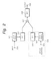
- Fig. 2 is a block diagram showing another example of the structure of a reverberation adding apparatus according to the present invention;
- Figs. 3A and 3B are schematic diagrams showing an impulse response corresponding to a reverberation of a conventional recursive filter and a reverberation according to an embodiment of the present invention;
- Fig. 4 is a block diagram showing an example of the structure of an impulse response collecting apparatus according to an embodiment of the present invention.
- Fig. 5 is a block diagram showing an example of the case that an impulse response is collected in a hall;
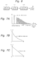
- Fig. 6 is a block diagram showing an example of an editing process for an impulse response;
- Fig. 7A to 7C are schematic diagrams showing examples of an editing process for an impulse response;
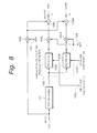
- Fig. 8 is a block diagram showing an example of the structure of a reverberation adding apparatus that performs a convolution calculation process using impulse response data.
- Fig. 9 is a block diagram showing a real example of the structure of a reverberation adding apparatus.
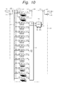
- Fig. 10 is a is a block diagram showing an example of the structure of an option board for use with the reverberator;
- Fig. 11 is a schematic diagram showing an example of the structure of a front panel of the reverberator;
- Fig. 12A to 12H are schematic diagrams showing examples of ripples displayed in a display area;
- Fig. 13A to 13H are schematic diagrams showing examples of ripples displayed in a display area;
- Fig. 14A to 14C are schematic diagrams showing other examples of ripples displayed in the display area;
- Fig. 15 is a schematic diagram showing a process performed in each DSP that performs a convolution calculation process;
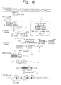
- Fig. 16 is a schematic diagram showing the details of the process performed in each DSP;
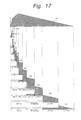
- Fig. 17 is a schematic diagram for explaining a convolution calculation process of which one impulse response is divided into a plurality of blocks;
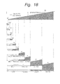
- Fig. 18 is a enlarged schematic diagram showing the convolution calculation process of which one impulse response is divided into a plurality of blocks;
- Fig. 19 is a is a block diagram showing an example of the structure of a convolution calculation filter of each DSP;
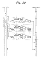
- Fig. 20 a schematic diagram showing a process of a convolution calculation filter on time axis;
- Fig. 21 is a block diagram showing a function of each DSP that performs a parallel process;
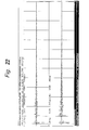
- Fig. 22 is a schematic diagram showing an original impulse response of a hall;
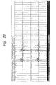
- Fig. 23 is a enlarged schematic diagram showing a part of the impulse response shown in Fig. 22;
- Fig. 24 is a schematic diagram showing an impulse response of which impulse response components corresponding to a direct sound and an initially reflected sound are removed from an original impulse response;
- Fig. 25 is a enlarged schematic diagram showing a part of the impulse response shown in Fig. 24;
- Fig. 26A to 26D are schematic diagrams for explaining a process for adjusting the balance of impulse response components corresponding to a direct sound and an initially reflected sound and an impulse response component corresponding to a reverberation;
- Fig. 27 is a schematic diagram showing an example of a variation of a frequency characteristic corresponding to a variation of a reverberation time:
- Fig. 28A to 28C are schematic diagrams for explaining a process for adjusting a reverberation time of an original impulse response;
- Fig. 29A to 29E are schematic diagrams for explaining a process for combining two different impulse responses;
- Fig. 30 is a block diagram showing an example of the structure for composing an initially reflected sound; and
- Fig. 31A and 31B are schematic diagrams for explaining a process for composing an initially reflected sound.
-
- Fig. 1 shows an example of a structure for performing a convolution calculation for an impulse response in time axis direction using an FIR (Finite Impulse Response) filter. Coefficients of an impulse response are required corresponding to samples of an input digital audio signal. Thus, when the impulse response data of 219 points (524,288 points ≒ 512 k points) is obtained with a digital audio signal at a sampling frequency of 48 kHz, the reverberation time becomes around 10 seconds.
- In Fig. 1, a digital audio signal is supplied from a terminal 310. The number of quantizing bits of the digital audio signal is for example 24. The sampling frequency of the digital audio signal is 48 kHz. The input signal is supplied to 512
k delaying circuits 311 connected in series. Each of the512k delaying circuits 311 has a delay of one sample.
Output signals of theindividual delaying circuits 311 are supplied to respectivecoefficient multiplying devices 312. Impulse response data of the first point to 512 k-th point is supplied to the delayingcircuits 311 with 24 quantizing bits. Thecoefficient multiplying devices 312 multiply respective output signals of the delayingcircuits 311 by respective impulse response data. The multiplied results are added by an addingdevice 313. The added result is supplied as reverberation data against the input data to a terminal 314. - Fig. 2 shows another example of the structure of the reverberation adding apparatus. In this example, after an input digital audio signal and impulse response data are converted into frequency element data corresponding to Fourrier transform method and then a convolution calculation process is performed for the frequency element data. Referring to Fig. 2, an input digital audio signal is supplied from a terminal 320. Data for samples corresponding to a required reverberation time (namely, data for 512 k points) is stored in a
memory 321. Data stored in thememory 321 is supplied to an FFT (Fast Fourrier Transform)circuit 322. TheFFT circuit 322 performs fast Fourrier transform for the data received from thememory 321 and outputs frequency element data. Likewise, impulse response data is supplied from a terminal 323. The impulse response data is stored in amemory 324. The impulse response data is supplied to anFFT circuit 325. TheFFT circuit 325 performs fast Fourier transform for the impulse response data received from thememory 324 and outputs frequency element data. Since the impulse response data is known, theFFT 325 and thememory 324 may be composed of aROM 326. - Output data of the
FFT circuits device 327. The multiplyingdevice 327 multiplies the output data of theFFT circuit 322 by the output data of theFFT circuit 325 in such a manner that the frequency components thereof match. The multiplied result is supplied to anIFFT circuit 328. TheIFFT circuit 328 performs inversely fast Fourrier transform for the data received from the multiplyingdevice 327 and outputs the resultant data as time axis data to a terminal 329. - As shown in Fig. 1, in the convolution calculation process for an impulse response on time base, a large number of delaying
circuits 311 and a large number ofcoefficient multiplying devices 312 are required. In contrast, the hardware scale of the structure shown in Fig. 2 is small. However, since input data corresponding to a desired reverberation time should be temporarily stored to thememory 321 and a convolution calculation process should be performed for the input data, a large delay takes place between the input signal and the output signal. To solve such a problem, a method for dividing an impulse response on time base and performing a convolution calculation process for input data corresponding to each divided impulse response has been proposed (as Japanese Patent Publicized Publication No. 8-501667). - The preferred embodiments of the present invention can be applied to a reverberation adding apparatus corresponding to any method. In a method according to an embodiment of the present invention, the hardware scale for the convolution calculation process is small. The delay time is small. An impulse response is divided on time base. A convolution calculation process for each divided impulse response and audio data is processed in parallel.
- Figs. 3A and 3B show the relation between reverberation according to the invention and reverberation of a conventional recursive filter. Fig. 3A shows reverberation of the conventional recursive filter. The reverberation shown in Fig. 3A is generated in the following manner. Direct sound is delayed by a predetermined time period and thereby initial reflection sound is generated. The initial reflection sound is further delayed by a predetermined time period. Reverberation generated by the filter is added. The generated reverberation attenuates corresponding to a simple attenuation curve. In contrast, according to the embodiment of the present invention, since reverberation is generated with an impulse response corresponding to really recorded data, the reverberation corresponds to acoustic characteristics of a real hall or the like (namely, it does not correspond to a simple attenuation curve).
Thus, according to the embodiment of the present invention, as mentioned in Fig. 3B, more natural and high quality reverberation can be obtained. - According to an embodiment of the present invention, an impulse response collecting method for obtaining natural reverberation is accomplished. Fig. 4 shows an example of the structure of an impulse
response collecting apparatus 97 according to an embodiment of the present invention. In this example, the impulseresponse collecting apparatus 97 measures an impulse response of a steel-plate echo apparatus 92. The impulseresponse collecting apparatus 97 can be composed of for example a personal computer. Theapparatus 97 generates a signal for measuring an impulse response and outputs the signal to a measurement object. In addition, theapparatus 97 collects measured results and converts them into impulse response data. The impulse response data is stored as for example a file. - A measurement
signal generating portion 90 generates a TSP (Time Stretch Pulse) signal for measuring an impulse response. The TSP signal is a kind of a sweep signal. When generating impluse signal is convluated by an inverse function to TSP signal, an impulse signal is obtained. To measure the impulse response, it is preferred to directly generate the impulse signal. However. it is difficult to measure the impulse signal directly generated. Thus, generating impluse signal is convoluted by inverse function to TSP signal, the TSP signal generated by the measurementsignal generating portion 90 is supplied to a D/A converter 91. The D/A converter 91 converts the TSP signal as a digital signal into an analog signal. The resultant analog signal is supplied to a steel-plate echo apparatus 92. - The steel-
plate echo apparatus 92 generates reverberation with the input TSP signal. The reverberation is output as analog audio signals on left (L) and right (R) channels. The analog audio signals on L and R channels are supplied to an A/D converter 93. The A/D converter 93 converts the analog audio signals on L and R channels into respective digital audio signals. The A/D converter 93 samples the digital audio signals at a sampling frequency of 48 kHz or 96 kHz with 24 quantizing bits. Output signals on L and R channels of the A/D converter 93 are supplied to an impulseresponse collecting apparatus 97. The input signals of the impulseresponse collecting apparatus 97 are stored to a hard disk unit or a memory (not shown). - The measurement
signal generating portion 90 generates the TSP signal N times. A synchronously addingportion 94 synchronously adds N output signals of the measurementsignal generating portion 90. The synchronously adding process is performed in such a manner that the output signals of the synchronously addingportion 94 are synchronized corresponding to the generation timing of the TSP signal. By synchronously adding N signals, only reproducible signals are added. Thus, since noise components that generate at random are not added, the S/N ration of the resultant signal can be improved. In other words, the S/N ratio of the resultant signal is improved by (10 log N) dB. For example, with N = 16, the S/N ratio of the resultat signal is improved by 12 dB. - The synchronously added signals on L and R channels are supplied to an impulse
response converting portion 95. In the impulseresponse converting portion 95, a convolution calculation with the TSP siginal is performed to a supplied digital audio signal. Thus, the TSP signal is converted into an impulse signal. The measured result is converted into an impulse response corresponding to reverberation generated with the impulse signal. The impulse response data has peak values obtained at intervals corresponding to the sampling frequency. After the A/D converter 93 samples a signal with 24 quantizing bits, the number of quantizing bits becomes 32. -
Impulse response data 96L on L channel andimpulse response data 96R on R channel that are supplied from the impulseresponse converting portion 95 are stored to a predetermined record medium such as a CD-ROM or an MD. Alternatively, the impulseresponse collecting apparatus 97 may be provided with an interface such as Ethernet so as to supply the impulse response data to an external apparatus. - Fig. 5 shows an example of the case that an impulse response is collected in a hall. Referring to Fig. 5, a
hall 101 has astage portion 101A and aguest seat portion 101B. Asound source 102 is disposed at a particular position of thestage portion 101A. Thesound source 102 is a dodecahedron speaker of which 12 speakers are disposed in 12 directions on a sphere. Amicrophone 103L on L channel and amicrophone 103R on R channel are disposed in theguest seat portion 101B. - A TSP signal is supplied from an impulse
response collecting apparatus 97 to a D/A converter 91. The D/A converter 91 converts the TSP signal as a digital signal into an analog signal. The analog signal is supplied to anamplifier 100. Theamplifier 100 amplifies the analog signal. The amplified signal is supplied to thesound source 102. Thesound source 102 reproduces the amplified signal as sound. The reproduced sound is collected by themicrophones microphones D converter 93. The A/D converter 93 samples the output signals of themicrophones response collecting apparatus 97. The process of the impulseresponse collecting apparatus 97 is the same as the process of the above-described steel-plate echo apparatus 92. - In this example, the position of the
sound source 102 is varied and impulse response data corresponding to varied positions is collected. In addition, the brands of the speakers used as thesound source 102 are also changed and impulse response data corresponding to the individual brands of the speakers is collected. Likewise, the positions and brands of themicrophones hall 101 are collected. When reverberation is added, one of these types can be selected as variations of reverberation. - On the other hand, the
impulse response data response converting portion 95 can be edited. Fig. 6 shows a flow of an editing process of impulse response data. Referring to Fig. 6,impulse response data 110 is supplied to anediting process portion 111. Figs. 7A, 7B, and 7C show examples of theediting process 111. As shown in Fig. 7A, a system delay takes place in data due to propagation of sound (a system delay portion is denoted by "A" in Fig. 7A). Theediting process portion 111 sets the value of the system delay portion to "0" so as to remove noise therefrom. - At the last half of the data, a fade-out process is performed so as to converge the last end of the data at [0]. With the fade-out process. noise of a low level portion of the second half of the signal is removed. Figs. 7B and 7C show examples of the fade-out process.
- Fig. 7B shows an example of which the fade-out process is performed corresponding to an attenuation exponential function. In Fig. 7B, the original impulse response is denoted by h(n) and the fade-out function is denoted by F0(n) (where n represents a point of impulse response data). It should be noted that a point of impulse response data corresponds to a sampling point of a digital audio signal. In the case of n ≤ 0, the relation of F0(n) = 1 is satisfied. In contrast, in the case of n > 0, F0(n) represents an attenuation exponential function as shown in Fig. 7B.
- Output data x(n) is represented by the following expression (1).
- It should be noted that the fade-out function is not limited to an attenuation exponential function. For example, as shown in Fig. 7C, the fade-out function may be a function having a linear attenuation characteristic.
- The number of points of the impulse response data can be adjusted corresponding to the process capability of the reverberator that adds reverberator to an audio signal with such data of the fade-out process. In the case that the number of points of impulse response data is limited to a predetermined value (for example, 256 k points ≒ 262,144 points), as shown in Fig. 7A, at the 128 k-th point, the fade-out process is started and at the 256 k-th point, the data becomes [0].
- As an example of the
editing process 111, a level adjusting process may be performed. The edited impulse response data is recorded as anFIR filter coefficient 112 for a convolution calculation process of the FIR filter to for example a CD-ROM 45. - In addition to impulse response data, data that represents a feature of the impulse response data is stored as additional data to the CD-
ROM 45. The additional data contains for example data that represents a reverberation time of an impulse response, start/end point values of a direct sound and an initially reflected sound (for example, the value of an input point is "1"), and a start point value of a reverberation. For example, a plurality of types of impulse responses collected by a steel-plate echo apparatus, one type of impulse response of a hall, and additional data corresponding to each impulse response are recorded on the CD-ROM 45. In the case of the steel-plate echo apparatus, since the reverberation time can be varied, a plurality of types of impulse responses corresponding to a plurality of reverberation times are collected. - Fig. 8 shows an example of the structure of a reverberator that performs a convolution calculation process with impulse response data generated in the above-described manner. Referring to Fig. 8, a digital audio signal is input from an
input terminal 120. The input signal is supplied to a multiplyingdevice 126. In addition, the input signal is supplied to apre-delaying portion 121. Thepre-delaying portion 121 delays the input data. Output data of thepre-delaying portion 121 is supplied to a convolutioncalculation process portion 122. - The convolution
calculation process portion 122 is composed of FIR filters on L and R channels (namely, afilter 122L and afilter 122R). Theimpulse response data response collecting apparatus 97 are supplied as FIR filter coefficients on L and R channels fromterminals impulse response data - The
filters impulse response data impulse response data filters devices - The multiplying
devices devices 126, and the addingdevices terminals device 126 and the multiplyingdevices calculation process portion 122. The addingdevices output terminals - Fig. 9 shows a detailed example of the structure of the reverberator. In the
reverberator 1, digital audio signals of two channels (channel I and channel 2) are input from a digitalaudio input terminal 10 corresponding to AES/EBU (Audio Engineering Society/European Broadcasting Union) standard. The digital audio signals received from theinput terminal 10 are supplied to aninput switcher 12 through adigital inputting portion 11. - In this example, the sampling frequency and the number of quantizing bits of the input digital audio signals are 48 kHz and 24 bits, respectively. When an option board 50 (that will be described later) is connected to the
reverberator 1, the sampling frequency of digital audio signals handled by thereverberator 1 can be doubled (namely, 96 kHz). In addition, digital audio signals at a sampling frequency of 44.1 kHz can be handled by thereverberator 1. In this case, when theoption board 50 is connected to thereverberator 1, signals at a sampling frequency of 88.2 kHz can be handled by thereverberator 1. - When analog audio signals are input to the
reverberator 1, analogaudio input terminals input terminals AID converter 14 samples the audio signals at a sampling frequency of for example 48 kHz with 24 quantizing bits so as to convert these signals into respective digital audio signals. Output signals of the A/D converter 14 are supplied to aninput switcher 12. - The
input switcher 12 switches a source of input audio signals under the control of a controller 40 (that will be described later) or with a manual switch. Output signals of theinput switcher 12 are supplied to a DSP (Digital Signal Processor) 30 through a path 31. - The
input switcher 12 switches a source of input audio signals under the control of a controller 40 (that will be described later) or with a manual switch. Output signals of theinput switcher 12 are supplied to a DSP (Digital Signal Processor) 30 through a path 31. - The
DSP 30 has a DRAM (Dynamic Random Access Memory) and performs various control processes for input/output digital audio signals corresponding to a program received from thecontroller 40. TheDSP 30 supplies input digital audio signals toDSPs 32A to 32K that perform convolution calculation processes for obtaining impulse response data corresponding to a predetermined process. In addition, theDSP 30 generates initial reflection sound corresponding to the input signals. Moreover, theDSP 30 receives the result of the convolution calculation process for the impulse response data from a DSP 34 (that will be described later). - The
DSPs 32A to 32K divide input digital audio signals into blocks with predetermined sizes and perform convolution calculation processes for the divided blocks with the pre-supplied impulse response data. TheDSPs 32A to 32K have respective DRAMs with relevant capacities corresponding to the number of samples to be processed. In this example, each of theDSPs 32A to 32H has one DRAM. The DSP 32I has two DRAMs. Each of theDSPs - The results of the convolution calculation processes for the impulse response data for individual blocks performed by the
DSPs 32A to 32K are added by an addingdevice 33. The added result is supplied from the addingdevice 33 to theDSP 30 through aDSP 34. When theDSP 34 detects an overflow in the added result, theDSP 34 sets the data of the overflow to a predetermined value. - The
DSP 30 combines the input digital audio signals, the initial reflection sound, and the result of the convolution calculation process for the impulse response data received from theDSP 34 so as to add reverberation to the input digital audio signals.Output data 35 of theDSP 30 is supplied to anoutput switcher 18. - The generated reverberation and non-processed input digital audio signals are referred to as "wet component" an "dry component", respectively. The
DSP 30 can vary the mixing ratio of the wet component and the dry component on each of L and R channels. In addition, theDSP 30 adjusts the levels of the output signals. - A clock signal FS or 2FS with a frequency corresponding to the sampling frequency of the handled digital audio signals is supplied to the
DSP 30. TheDSP 30 processes signals corresponding to the clock signal FS or 2FS. - The
output switcher 18 selects an output destination of output signals under the control of thecontroller 40 or with a manul switch. The output signals are digital audio signals or analog audio signals. Theoutput switcher 18 supplies digital audio signals of two channels tooutput terminal 20 corresponding to the AES/EBU standard through adigital outputting portion 19. The digital audio signals that are output from theoutput switcher 18 are supplied to a D/A converter 21. The D/A converter 21 converts the digital audio signals received from theoutput switcher 18 into analog audio signals. The analog audio signals on L and R channels are supplied toanalog output terminals - In this example, the
input terminal 10, theinput terminals output terminal 20, and theoutput terminals - The
output switcher 18 allows the reverberation adding process in thereverberator 1 for the input audio signals to be bypassed. When the reverberation adding process is bypassed, the input digital audio signals are directly supplied to theoutput switcher 18 through theinput switcher 12 and abypass path 17. - All portions of the
reverberator 1 are controlled by thecontroller 40. Thecontroller 40 comprises for example a CPU (Central Processing Unit), a RAM (Random Access Memory), a ROM (Read Only Memory), and predetermined input/output interfaces. The ROM stores a boot program for starting up the system and serial number. The RAM is a work memory with which the CPU operates. An external program is loaded to the RAM. - The
controller 40 is connected to abus 41 with for example eight bits parallel. Thebus 41 is connected to theDSP controller 40 communicates with each of theDSPs bus 41. Thus, thecontroller 40 supplies programs to theDSPs controller 40 exchanges data and commands with theDSPs - As described above, the
input switcher 12 and theoutput switcher 18 are connected to for example the bus 41 (not shown) and controlled by thecontroller 40. - For example, a
display unit 42 that is a full-dot LCD (Liquid Crystal Display) is connected to thecontroller 40. Thedisplay unit 42 displays data generated by thecontroller 40. - The inputting
portion 43 has a plurality of inputting means (for example, a rotary encoder for inputting data corresponding to the rotation angle and a plurality of push switches). By operating these inputting means, relevant control signals are supplied from the inputtingportion 43 to thecontroller 40. Corresponding to the control signals, thecontroller 40 supplies predetermined programs and parameters to theDSPs - The
reverberator 1 has a CD-ROM (Compact Disc-ROM)drive 44. A CD-ROM 45 is loaded to the CD-ROM drive 44. Data and programs are read from the CD-ROM 45. The data and programs that have been read from the CD-ROM 45 are supplied to thecontroller 40. - For example, impulse response data has been recorded on the CD-
ROM 45. The impulse response data is read from the CD-RM 45 and supplied to thecontroller 40. The data is supplied from thecontroller 40 to theDSPs 32A to 32K. TheDSPs 32A to 32K perform convolution calculation processes for impulse response data corresponding to the received impulse response data. - The
reverberator 1 has an external interface MIDI (Musical Instrument Digital Interface). An MIDI signal is supplied from anMIDI input terminal 46 to thecontroller 40. Corresponding to the MIDI signal, thecontroller 40 controls a relevant function of thereverberator 1. Thecontroller 40 generates and outputs the MIDI signal. Thecontroller 40 can edit the MIDI signal received from theMIDI input terminal 46 and outputs the resultant signal. The MIDI signal is supplied from thecontroller 40 to an external apparatus through theMIDI output terminal 47. An MIDI through-terminal 48 is used to directly output the MIDI signal received from theMIDI input terminal 46. - When the
option board 50 is connected to thereverberator 1, extended functions can be obtained. As an example of the extended functions, two more digital audio signals at a sampling frequency of 48 kHz can be handled. The digital audio signals of two channels (channels 3 and 4) are received from a terminal 15 through theoption board 50. The digital audio signals are supplied to theinput switcher 12 through the digital inputtingportion 16. In addition, digital audio signals of two channels corresponding to a process of theoption board 50 are output to a terminal 24 through the digital outputtingportion 23. The digital audio signals are output to an external apparatus from the terminal 24 through theoption board 50. - As another example of the extended functions, audio signals of two channels (
channels 1 and 2) can be handled at a sampling frequency of 96 kHz that is twice as high as the normal sampling frequency. - The
option board 50 and thereverberator 1 are connected withterminals 51 to 56, 15, and 24. Fig. 10 shows an example of the structure of theoption board 50. Theoption board 50 performs an extended convolution calculation process for impulse response data using theDSPs 32A to 32K and the addingdevice 33. Thus, theoption board 50 hasDSPs device 61, and aDSP 62. TheDSPs DSPs 32A to 32K shown in Fig. 9, respectively. In addition, theDSP 62 corresponds to theDSP 34 shown in Fig. 9. - A bus 41' of the
option board 50 is connected to thebus 41 of thereverberator 1 through a terminal 56. TheDSPs option board 50 can communicate with thecontroller 40 through the bus 41'. - The
DSPs DSPs 32A to 32K. Input digital audio signals are supplied from theDSP 30 to theDSPs DSPs device 33 through theterminals device 33 adds the results of the convolution calculation processes of theDSPs other DSPs 32A to 32K. - On the other hand, the
DSPs 60A to 60M perform the convolution calculation processes in parallel with those of theDSPs 32A to 32M shown in Fig. 9. Input digital audio signals are supplied from theDSP 30 to theDSPs 60A to 60M through the terminal 51. - When digital audio signalas of four channels (
channels 1 to 4) are processed with theoption board 50, theDSPs 32A to 32M perform convolution calculation processes for digital audio signals ofchannels DSPs 60A to 60M perform convolution calculation processes for digital audio signals ofchannels DSPs DSPs - The results of the convolution calculation processes of the
DSPs 60A to 60M are supplied to the addingdevice 61. The added result of the addingdevice 61 is supplied to theDSP 62. As with theDSP 34, theDSP 62 performs an overflow process. The resultant signals are supplied to theDSP 30 through the terminal 52. TheDSP 30 adjusts the ratio of a dry component and a wet component and the mixing ratio of signals of individual channels and supplies the resultant data to theoutput switcher 18. - The
option board 50 also has a digital audiosignal input terminal 63 and a digital audiosignal output terminal 64 corresponding to AES/EBU standard. Signals of two channels (channel 3 and 4) are input to theinput terminal 63. The input signals are supplied to theinput switcher 12 through the terminal 15. Likewise, output signals of two channels (channels 3 and 4) are supplied from theoutput switcher 18 to theoption board 50 through the terminal 24 and then output from theoutput terminal 64. In this example, theterminals - Fig. 11 shows an example of a
front panel 200 of thereverberator 1. Four mounting holes are formed at four corners of thefront panel 200. With the four mounting holes, thereverberator 1 can be mounted to a rack. Apower switch 201 is disposed on the left of thepanel 200. Below thepower switch 201, a CD-ROM loading portion 202 is disposed. A CD-ROM 45 is loaded to a CD-ROM drive 44 through the CD-ROM loading portion 202. With aswitch 205, the CD-ROM 45 is loaded and unloaded to/from the CD-ROM drive 44 through the CD-ROM loading portion 202. - A
display portion 203 is disposed at a nearly center position of thepanel 200. Thedisplay portion 203 corresponds to theLCD 42 shown in Fig. 9. On the right of thedisplay portion 203, arotary encoder 204 is disposed. Below thedisplay portion 203,function keys rotary encoder 204 and thefunction keys 206 to 209, the user can select one of the functions of thereverberator 1 and input data thereto. - The
display portion 203 displays various data corresponding to the selected function. In this example, thedisplay portion 203 displays parameters corresponding to a selected reverberation type. Thedisplay portion 203 is largely separated into adisplay area 210 and adisplay area 211. Thedisplay area 210 visually displays parameters corresponding to the selected reverberation type. Thedisplay area 211 displays parameter names and parameter values. - Data displayed in the
display area 211 corresponds to the function switches 206 to 209 disposed below thedisplay portion 203. When one of the function switches 206 to 209 is pressed, a parameter displayed above the function switch that has been pressed is selected. By turning therotary encoder 204, the value of the selected parameter is varied. Another page can be displayed on thedisplay portion 203. On another page, the value of another parameter can be varied. - In the embodiment, the
display area 210 displays ripples corresponding to a parameter that is being currently set. Thus, the user can visually know the effect of reverberation (spatial impression) corresponding to the parameter value. Figs. 12A to 12H and Figs. 13A to 13H show examples of ripples displayed in thedisplay area 210. As the reverberation time is prolonged, the number of wavers of ripples is increased in the order from Figs. 12A to 12H to Figs. 13A to 13H. - In this example, the ripples are displayed in 16 levels of the minimum value to the maximum value of the reverberation time. The ripples in 16 levels are proportional to the reverberation time. Ripple display data is stored in the CD-
ROM 45. When thereverberator 1 gets started, ripple display data is read from the CD-ROM 45 and stored in the RAM of thecontroller 40. Alternatively, the ripple display data may be prestored in the ROM of thecontroller 40. Once the parameter value of the reverberation time is set, ripples are displayed corresponding to the parameter value that has been set. - When ripples are displayed in the
display area 210, the user can visually know the effect of the reverberation that has been set. In other words, the user can visually know the spatial impression of the reverberation with ripples displayed in thedisplay area 210. - In the example, ripples are displayed in the upper right direction of the
display area 210. However, ripples may be displayed with a different pattern. Figs. 18A, 18B, and 18C show other examples of ripples displayed in thedisplay area 210. The center point and spreading direction of ripples can be freely set. The center position of ripples can be set at the left end of the display area 210 (see Fig. 18A). Alternatively, the center position of ripples can be set at the center of the display area 210 (see Fig. 18B). A section of ripples may be displayed in the display area 210 (see Fig. 18C). In addition, the shape of ripples can be varied corresponding to the selected reverberation type. In this example, ripples are displayed as a still pattern. However, when a plurality of pages of ripple display data is prepared for each parameter and they are successively displayed, ripples can be displayed as an animated pattern. - Next, convolution calculation processes for impulse response data performed by the
DSPs 32A to 32M and theDSPs 60A to 60M will be described. In this example for simplicity, only convolution calculation processes performed by only theDSPs 32A to 32K without the use of theoption board 50 will be described. - Fig. 15 shows a process performed by each of the
DSPs 32A to 32K. Impulse response data is read from for example the CD-ROM 45 under the control of thecontroller 40 and supplied to theDSPs 32A to 32K. The impulse response data that is read from the CD-ROM 45 is stored to the DRAMs of theDSPs 32A to 32K. Each of theDSPs 32A to 32K divides impulse response data at predetermined intervals on time axis corresponding to the process block sizes assigned thereto. - For simplicity, a
DSP 32 that represents all theDSPs 32A to 32K will be described. The data unit of impulse response data processed by theDSP 32 is denoted by N. In this example, since theDSP 32A performs a convolution calculation process for impulse response data of 128 points, the data unit N is 128. In the following description, one word corresponds to data of one sample of a digital audio signal. Thus, one word has a time period of (1/sampling frequency). The number of quantizing bits of digital data is 24 bits. - Input data supplied to the
DSP 32 is divided as block data of N words. Thus, the time period for the first N words is the time period for inputting the data. The input data of N words is stored to the DRAM of theDSP 32. In the time period of the next N words, a convolution calculation process is performed for impulse response data corresponding to input data of N words stored in the DRAM. After the convolution calculation process is completed, the result of the process for N words is output. Thus, in the process for N words, output data is delayed by 2N words to input data. - Fig. 16 shows the process of the
DSP 32 in detail. TheDSP 32 performs a convolution calculation process for impulse response data by known recursive convolution overlap save method. - In other words, as shown in Fig. 16, an n-
th block 80B and an (n-1)-th block 80A that immediately precedes theblock 80B are supplied every N words on time axis. The n-th block 80B and the (n-1)-th block 80A are converted intofrequency element data 81 composed of areal part 81A of (N+1) words and animaginary part 81B of (N-1) words by DFT (Discrete Fourier Transform) method. - On the other hand,
real data 82A and zero data 82B ofimpulse response data 82 have been converted intofrequency element data 83 composed of areal part 83A of (N+1) words and animaginary part 83B of (N-1) words by DFT method. - The real part and imaginary part of
frequency element data 81 of the input data and the real part and imaginary part of thefrequency element data 83 of the impulse response are multiplied, respectively. The multiplied results of the same frequency components are added. Namely, filter process (convolution calculation process) is performed. Thus,frequency element data 84 composed of a real part 84A of (N+1) words and an imaginary part of (N-1) words is obtained. The IDFT process that is an inverse process of the DFT process is performed for thefrequency element data 84. Thus,data 86 of 2N words on time axis is obtained. - As the results of the IDFT process, as represented by
data N word portions data - When the block size is increased, a convolution calculation process is performed for more impulse response data. Thus, a longer reverberation time can be obtained. However, as described above, an output block is delayed by two blocks against an input block. Consequently, when the size of each block is increased, the delay time of an output component of the reverberation process adversely becomes long. To solve such a problem, according to the embodiment of the present invention, a process for obtaining a desired reverberation time is performed in parallel for a plurality of blocks each of which is composed of a predetermined number of points (words).
- Figs. 17 and 18 show a convolution calculation process according to the embodiment of the present invention. In the convolution calculation process, a digital audio signal is divided to a plurality of blocks. For example, a convolution calculation process for 218 words (256 k words) is considered. In this case, a convolution calculation process is performed for a digital audio signal with impulse response data of 256 k words (256 k points). When the sampling frequency is 48 kHz, a reverberation time of around 5.3 seconds is obtained. When the sampling frequency is 44.1 kHz, a reverberation time of around 5.9 seconds is obtained.
- As shown in Fig. 17, the impulse response data of 256 k words is divided into two portions. The temporally earlier portion of the two portions is further divided into two portions. In such a manner, the earlier portion on time axis is successively divided into two portions. The later portion on time axis is successively divided into two portions. Thus, two blocks with the same size are formed.
- Fig. 18 is an enlarged view showing a top portion A of 8 k words shown in Fig. 17. Likewise, the portion A is divided into two portions. The first 256-words portion is divided into two blocks each of which has 128 words. A convolution calculation process is performed for impulse response data of the two blocks. Thus, the reverberation component is delayed by 256 words of the first portion. However, when the sampling frequency is 48 kHz, the delay is as small as 5 msec. Thus, it does not adversely affect reverberation.
- In the case of 218 words (256 k words), a pair of two 27 words (128 words) blocks, a pair of two 28 words (256 words) blocks, a pair of two 29 words (512 words) blocks, a pair of two 210 words (1 k words) blocks, a pair of two 211 words (2 k words) blocks, a pair of two 212 words (4 k words) blocks, a pair of two 213 words (8 k words) blocks, a pair of two 214 words (16 k words) blocks, a pair of two 215 words (32 k words) blocks, and a pair of two 216 words (64 k words) blocks (namely, pairs of two 2n words blocks) are formed.
- Each of the
DSPs 32A to 32K performs a convolution calculation process for the relevant pair with the same block size. In other words, as shown in Figs. 17 and 18, theDSPs 32A to 32K divide their input data as follows. TheDSP 32A divides the input data into blocks each of which is composed of 128 words. TheDSP 32B divides the input data into blocks each of which is composed of 256 words. TheDSP 32C divides the input data into blocks each of which is composed of 512 words. TheDSP 32D divides the input data into blocks each of which is composed of 1 k words. TheDSP 32E divides the input data into blocks each of which is composed of 2 k words. TheDSP 32F divides the input data into blocks each of which is composed of 4 k words. TheDSP 32G divides the input data into blocks each of which is composed of 8 k words. TheDSP 32H divides the input data into blocks each of which is composed of 16 k words. The DSP 32I divides the input data into blocks each of which is composed of 32 k words. Each of theDSPs - For a convolution calculation process for blocks in the range from 128 words to 32 k words, each DSP performs the process for a pair of blocks with the same block size on time division basis.
- In other words, each of the
DSPs 32A to 32K performs a convolution calculation process for divided block data with relevant impulse response data. The second pair member of each pair is delayed by one block against the first pair member. Thus, each of theDSPs 32A to 32K successively outputs two blocks with the same block size. The addingdevice 33 adds the output blocks of theDSPs 32A to 32K and generatesreverberation data 88. - When input data is successively processed by the
DSPs 32A to 32K in their assigned periods and the results are added, reverberation can be added to the successive data. - Fig. 19 shows an example of the structure of a
convolution calculation filter 70 used in each of theDSPs 32A to 32K. Theconvolution calculation filter 70 performs a convolution calculation process. Theconvolution calculation filter 70 is accomplished by a predetermined program supplied from thecontroller 40 to theDSPs 32A to 32K. Referring to Fig. 23, a digital audio signal is input from a terminal 71. The input digital audio signal is supplied to aDFT circuit 72. TheDFT circuit 72 converts the digital audio signal on time axis into frequency element data. Output data of theDFT circuit 72 is supplied to a multiplyingdevice 74 and adelaying circuit 73. - The delaying
circuit 73 delays the input digital audio signal by N words. In other words, theDSPs circuit 73 is supplied to a multiplyingdevice 76. - The multiplying
device 74 receives a filter coefficient A from a terminal 75. The filter coefficient A is impulse response data that has been processed by DFT method. The multiplyingdevice 74 multiplies the output data of theDFT circuit 72 by the relevant frequency element of the filter coefficient A. Likewise, the multiplyingdevice 76 performs the same process as the multiplyingdevice 74. In other words, the multiplyingdevice 76 receives a filter coefficient B from a terminal 77. The filter coefficient B is impulse response data that has been processed by DFT method. The multiplyingdevice 76 multiplies the output data of the delayingcircuit 73 by the relevant frequency element of the filter coefficient B. - The multiplied results of the multiplying
devices device 78. The added result is supplied to anIDFT circuit 79. TheIDFT circuit 79 converts the frequency element data into data on time axis and outputs the resultant data from a terminal 80. - Since the
convolution calculation filter 70 performs a convolution calculation process for two blocks of data of which one block is delayed by N words (namely, one block) against the other block and outputs data of two blocks. As was described with reference to Fig. 16, the first pair member of each pair is discarded. - Fig. 20 shows a process on time axis performed by the
convolution calculation filter 70 shown in Fig. 19. The left end and right end of Fig. 20 show input data and output data, respectively. It is assumed that in Fig. 20, time passes downwards. - Referring to Fig. 20, a plurality of
filters 70 are shown. However, in reality, these processes are performed by onefilter 70 at different timings. Thus, the result of the DFT process at the preceding timing is delayed by the delayingcircuit 73. The delayed result is used for the filter process at the next timing. Consequently, output data delayed by two blocks against input data is successively obtained. - Fig. 21 is a functional block diagram showing an outline of parallel processes of the
DSPs 32A to 32K. Input data is supplied to theDSPs 32A to 32K in parallel. TheDSPs DSPs 32A to 32K is delayed by 2 N words. The delayed results are supplied to an adding device 22. - For example, the
DSP 32A divides input data into blocks each of which is composed of N = 128 words, performs a convolution calculation process for the divided blocks, and outputs the calculated result that has been delayed by 2N words against the input data. Thereafter, theDSP 32A receives the next blocks each of which is composed of N words and repeats the same process for the blocks. This process applies to each of theDSPs 32B toDSP 32K. - Next, as features of an embodiment of the present invention an editing process and a combining process for impulse responses will be described. As described above, data of a plurality of impulse responses and additional data corresponding thereto are read from the CD-
ROM 45 to the reverberation adding apparatus. For example, a plurality of types of impulse responses collected by a steel-plate echo apparatus, one type of impulse response collected from a hall, and additional data corresponding to each impulse response are read from the CD-ROM 45 to the reverberation adding apparatus. As described above, as the additional data, data that represents a reverberation time of each impulse response, start/end point values of a direct sound and an initially reflected sound (for example, the value of an input point is "1"), and a start point value of each reverberation are used. Impulse responses are edited and combined by a software process of thecontroller 40. - Next, with reference to Figs. 22, 23, 24, and 25. as a first example of the impulse response editing process, a process for removing a direct sound and an initially reflected sound will be described. When a direct sound and an initially reflected sound are contained in a reverberation, a process as a simulator of a hall is performed. Thus, a direct sound and an initially reflected sound should be removed from a reverberation. Fig. 22 shows original impulse response data of a hall. The original impulse response data is read from the CD-
ROM 44. Referring to Fig. 22, the sampling frequency of the impulse response data is 96 kHz and 64 k points of 512 k points are shown. Fig. 23 is an enlarged view showing an initial response portion (4 k points) of the impulse response data shown in Fig. 22. - Figs. 24 and 25 show impulse response data of which impulse response components corresponding to a direct sound and an initially reflected sound are removed from original impulse response data, respectively. When impulse response components corresponding to a direct sound and an initially reflected sound are set to "0", the direct sound and the initially reflected sound can be removed from the original impulse response data. Fig. 24 shows an impulse response component for 64 k points against the impulse response data shown in Fig. 22. Fig. 25 is an enlarged view showing an impulse response component for 4 k points against the impulse response component shown in Fig. 24. In these drawings, upper impulse response components and lower impulse response components correspond to L channel and R channel, respectively.
- As described above, since additional data corresponding to the impulse response data shown in Fig. 22 contains information of start/end points of impulse response components corresponding to a direct sound and an initially reflected sound, the positions of the impulse response components corresponding to the direct sound and the initially reflected sound can be specified. When a fade-in operation is performed from the specified position, the initially reflected sound can be removed. However, a direct sound and an initially reflected sound can be removed without need to use the additional information. In other words, a portion after the maximum value of a waveform of an envelop of an impulse response until the slope of the envelop is inverted to plus is estimated as impulse response components corresponding to a direct sound or an initially reflected sound. Since a direct sound largely affects an reverberation, only the direct sound may be removed.
- Next, with reference to Figs. 26, a second example of the impulse response editing process will be described. In the second example, the balance of a direct sound, an initially reflected sound, and a reverberation is adjusted. Fig. 26A shows original impulse response data. In Fig. 26A, the start point of a direct sound and an initially reflected sound (denoted by N1), the end point thereof (denoted by N2), the start point of a reverberation (denoted by N3), and a reverberation time (denoted by To) are represented as additional data.
- With the additional data, original impulse response data is separated into impulse response components corresponding to a direct sound and an initially reflected sound (see Fig. 26B) and an impulse response component corresponding to a reverberation (see Fig. 26C). In the example shown in Figs. 26, since the impulse response components corresponding to the direct sound and the initially reflected sound are very large against the impulse response component corresponding to the reverberation, the levels of the impulse response components corresponding to the direct sound and the initially reflected sound are lowered. The resultant impulse response components are combined with the impulse response component corresponding to the reverberation. Fig. 26D shows the combined impulse response data. Alternatively, the level of the impulse response component corresponding to the reverberation can be raised. As another alternative method, the balance of impulse response components may be adjusted using a cross fade method. In other words, impulse response components corresponding to a direct sound and an initially reflected sound are faded out, whereas an impulse response component corresponding to a reverberation is faded in. The fade-in/out curves may be straight lines or exponential curves.
- Next, with reference to Figs. 27 and 28, a third example of the impulse response editing process will be described. In the third example, the reverberation time is adjusted. In the case of a steel-plate echo apparatus, when the reverberation time is varied, the frequency characteristic of the reverberation adding apparatus is also varied. Fig. 27 shows an example of measured results of frequency characteristics of different reverberation times at 0.2 sec steps (1.5 sec, 1.75 sec, 2.0 sec, ... 3.5 sec). Thus, to add a reverberation equivalent to that of a steel-plate echo apparatus to an audio signal, impulse responses corresponding to respective reverberation times are required. Thus, since the data amount for the impulse responses becomes huge, the storage capacity of the memory adversely increases.
- To solve such a problem, as shown in Figs. 28, impulse responses corresponding to representative reverberation times is provided. Impulse responses corresponding to other reverberation times are obtained by calculations. In reality, the range of a reverberation time is divided into a plurality of time zones. In each time zone, an impulse response corresponding to a desired reverberation time is obtained with the representative impulse responses. Fig. 28A shows an impulse response at reverberation time To = 4 sec. Fig. 28B shows an impulse response at reverberation time To = 3 sec. Fig. 28C shows an impulse response at reverberation time To = 2 sec. With an representative impulse response at To = 4 sec, impulse responses corresponding to reverberation times 2.25 sec, 2.5 sec, and 2.75 sec are obtained. In addition, with a representative impulse response at Tr = 2 sec, impulse responses at 1.25 sec. 1.5 sec, and 1.75 sec are obtained. Thus, in addition to the three representative impulse responses, impulse responses corresponding to nine types of reverberation times can be obtained.
- Next, a calculating method for obtaining an impulse response in a short reverberation time using a representative impulse response will be described. In this case, an original impulse response is multiplied by an exponential function so as to shorten a reverberation time. The shortened reverberation time is given as follows.where Trev: shortened reverberation time; To: reverberation time of original impulse response data; and Tx: exponential reverberation time multiplied by impulse response data.

- Thus, the following relation is satisfied.
- The exponential reverberation time can be expressed as follows.
- Next, an exponential function of which the reverberation time becomes Tx is obtained.
- The resultant exponential function is multiplied by representative impulse response data. Thus, the reverberation time can be adjusted to Tx.
- Next, with reference to Figs. 29, a fourth example of the impulse response editing process will be described. In the fourth example, a plurality of different impulse responses are combined and thereby a new impulse response is generated. Fig. 29A shows an impulse response of a steel-plate echo apparatus. Fig. 29B shows an impulse response of a hall. In the impulse responses of the steel-echo apparatus and the hall, with additional data, a point N1 at which impulse response components corresponding to a direct sound and an initially reflected sound end is obtained. In the examples shown in Figs. 29A and 29B, the point N1 of the impulse response corresponding to the direct sound is the same as that corresponding to the directly reflected sound. Alternatively, the point N1 of the impulse response corresponding to the direct sound may be different from that corresponding to the directly reflected sound.
- The impulse response components corresponding to the direct sound and the initially reflected sound are removed from the impulse response data of the steel-plate echo apparatus shown in Fig. 29A. Thus, the impulse response component corresponding to the reverberation is separated as shown in Fig. 29C. In addition, the impulse response component corresponding to the reverberation of the impulse response of the hall shown in Fig. 29B is removed. Thus, the impulse response components corresponding to the direct sound and the initially reflected sound are separated as shown in Fig. 29D. By combining these impulse response components, a combined impulse response as shown in Fig. 29E is generated. Instead of the separating process and the combining process, two impulse response components may be combined by a cross fade method using a straight line or an exponential function.
- Next, with reference to Figs. 30 and 31, a fifth example of the impulse response editing process will be described. In the fifth example, initially reflected sounds different from an original impulse response are combined. In Fig. 30, DL1, DL2,..., and DLn are delay devices with different delay amounts and connected in parallel. An initially reflected sound x0 with an original impulse response shown in Fig. 31A is supplied to the delay devices DL1 to DLn.
- Output signals of the delay devices DL1 to DLn are supplied to multiplying devices MP1 to MPn, respectively. The multiplying devices MP1 to MPn multiply the output signals of the delay devices DS1 to DLn by coefficients k1 to kn, respectively. The multiplying devices MP1 to MPn generate impulse response components x1 to xn corresponding to the initially reflected sound whose level has been adjusted at the positions corresponding to the delay amounts of the delay devices DL1 to DLn, respectively. The impulse response x0 of the original initially reflected sound and the generated impulse response components x1 to xn corresponding to the initially reflected sound are added by an adding device AD. Thus, as shown in Fig. 31B, the adding device AD outputs an impulse response component corresponding to an initially reflected sound that is different from the original impulse response. The process of the block diagram shown in Fig. 30 is executed by software of the
controller 40. - As a sixth example of the impulse response editing process, the value of a pre-delay that is a time period after an original audio signal is input until a reverberation is generated. In other words, the value of a pre-delay may be set to 0 or a negative value.
- The above-described impulse response editing/combining process can be performed by a switch operation of the reverberation adding apparatus or a rotating operation of a rotary encoder. In this case, additional data may be displayed on an LCD display portion. Parameters of reverberation time of an impulse response that has been edited may be displayed. In addition, an impulse response may be displayed.
- In the embodiment, the impulse
response collecting apparatus 97 is independent from thereverberator 1. However, it should be noted that the present invention is not limited to such a structure. In other words, thereverberator 1 may have a measurementsignal generating portion 90, a synchronously addingportion 94, and an impulseresponse converting portion 95. The measurementsignal generating portion 90 generates a TSP signal. These portions can be composed of a CPU and several peripheral parts. Alternatively, theDSP 30 andDSP 34 of thereverberator 1 may be used. When thereverberator 1 has a function for collecting impulse response data, the user can obtain an original sound effect. - In the embodiment, the convolution calculation process for impulse response data is performed by hardware such as
DSPs 32A to 32K. However, it should be noted that the convolution calculation process may be performed by software. Likewise, the processes of theDSPs - As described above, according to embodiments of the present invention, since a sound effect is obtained by performing a convolution calculation process for a collected impulse response and audio data, a natural, high quality result is obtained. In addition, since an original impulse response is edited or combined with another one, various sound effects can be obtained as the user desires. In other words, according to embodiments of the present invention, by editing an impulse response or combining impulse response components, the following effects can be obtained.
- Firstly, a desired reverberation time can be obtained by an adjustment. In this case, with an impulse response corresponding to a representative reverberation time, a desired reverberation time can be obtained by a calculation. Thus, the data mount of an impulse response can be decreased. Secondly, impulse response components corresponding to a direct sound and initially reflected sounds can be removed. Their levels can be adjusted. A desired initially reflected sound can be composed. Thirdly, by combining different impulse responses, a new impulse response can be generated. Fourthly, a pre-delay can be adjusted to a desired value. Since an impulse response can be edited and impulse responses can be combined, the operational characteristics of a conventional digital reverberation adding apparatus can be accomplished. In addition, a natural, high quality reverberation can be added to an original audio signal.
- In so far as the embodiments of the invention described above are implemented, at least in part, using software-controlled data processing apparatus, it will be appreciated that a computer program providing such software control and a storage medium by which such a computer program is stored are envisaged as aspects of the present invention.
- Having described a specific preferred embodiment of the present invention with reference to the accompanying drawings, it is understood that the invention is not limited to that precise embodiment, and that various changes and modifications may be effected therein by those skilled in the art without departing from the scope or the spirit of the invention as defined in the appended claims.
Claims (10)
- A sound effect adding apparatus for performing a convolution calculation process for an input digital audio signal and impulse response data and thereby adding a sound effect to the input digital signal, comprising:impulse response editing means for editing an original impulse response; andconvoluting means for performing a convolution calculation process for the edited impulse response and a digital audio signal.
- The sound effect adding apparatus as set forth in claim 1,
wherein a plurality of different impulse responses are reproduced from a record medium. - The sound effect adding apparatus as set forth in claim 1,
wherein said impulse response editing means edit the original impulse response by using a incidental information that represents characteristic of the original impulse response. - The sound effect adding apparatus as set forth in claim 3,
wherein the incidental information includes for example data that represents a reverberation hours of the original impulse response, point values of start/end of a direct sound and an initial reflected sound and a start point value of a reverberation. - The sound effect adding apparatus as set forth in claim 1,
wherein the original impulse response is composed of a first impulse response and a second impulse response, the first impulse response corresponding to a direct sound and an initial reflected sound just after the digital audio signal is inputted the second impulse response corresponding to a reverberation after the first impulse response. - The sound effect adding apparatus as set forth in claim 5,
wherein said impulse response editing means removes at least an impulse response component corresponding to the direct sound from the first impulse response. - The sound effect adding apparatus as set forth in claim 5,
wherein said impulse response editing means adjusts the value of an impluse response component corresponding to at least the direct sound of the first impulse response and compositing the said second impluse response for an ajustment. - The sound effect adding apparatus as set forth in claim 5,
wherein said impulse response editing means generates an impulse response corresponding to a desired reverberation hours by using a plurality of representative impulse response components corresponding to different reverberation hours of the second impulse response by a calculation. - The sound effect adding apparatus as set forth in claim 5,
wherein said impulse response editing means combines a plurality of original impulse responses so as to generate a new impulse response. - The sound effect adding apparatus as set forth in claim 5,
wherein said impulse response editing means adjusts time called pre-delay after the said impulse response is input until a reverberation is generated.
Applications Claiming Priority (2)
| Application Number | Priority Date | Filing Date | Title |
|---|---|---|---|
| JP10272241A JP2000099061A (en) | 1998-09-25 | 1998-09-25 | Effect sound adding device |
| JP27224198 | 1998-09-25 |
Publications (3)
| Publication Number | Publication Date |
|---|---|
| EP0989543A2 true EP0989543A2 (en) | 2000-03-29 |
| EP0989543A3 EP0989543A3 (en) | 2003-03-05 |
| EP0989543B1 EP0989543B1 (en) | 2006-11-22 |
Family
ID=17511106
Family Applications (1)
| Application Number | Title | Priority Date | Filing Date |
|---|---|---|---|
| EP19990307560 Expired - Lifetime EP0989543B1 (en) | 1998-09-25 | 1999-09-24 | Sound effect adding apparatus |
Country Status (5)
| Country | Link |
|---|---|
| EP (1) | EP0989543B1 (en) |
| JP (1) | JP2000099061A (en) |
| AU (1) | AU5012499A (en) |
| DE (1) | DE69934069T2 (en) |
| DK (1) | DK0989543T3 (en) |
Cited By (14)
| Publication number | Priority date | Publication date | Assignee | Title |
|---|---|---|---|---|
| EP1463030A2 (en) | 2003-03-26 | 2004-09-29 | Yamaha Corporation | Reverberation sound generating apparatus |
| EP1603119A3 (en) * | 2001-07-10 | 2008-02-06 | Coding Technologies AB | Efficient and scalable parametric stereo coding for low bitrate audio coding applications |
| EP1590800B1 (en) * | 2003-02-06 | 2009-11-04 | Dolby Laboratories Licensing Corporation | Continuous backup audio |
| US8036767B2 (en) | 2006-09-20 | 2011-10-11 | Harman International Industries, Incorporated | System for extracting and changing the reverberant content of an audio input signal |
| US8180067B2 (en) | 2006-04-28 | 2012-05-15 | Harman International Industries, Incorporated | System for selectively extracting components of an audio input signal |
| US8605911B2 (en) | 2001-07-10 | 2013-12-10 | Dolby International Ab | Efficient and scalable parametric stereo coding for low bitrate audio coding applications |
| US9245520B2 (en) | 2009-10-21 | 2016-01-26 | Fraunhofer-Gesellschaft Zur Foerderung Der Angewandten Forschung E.V. | Reverberator and method for reverberating an audio signal |
| US9372251B2 (en) | 2009-10-05 | 2016-06-21 | Harman International Industries, Incorporated | System for spatial extraction of audio signals |
| US9431020B2 (en) | 2001-11-29 | 2016-08-30 | Dolby International Ab | Methods for improving high frequency reconstruction |
| JPWO2014069111A1 (en) * | 2012-11-02 | 2016-09-08 | ソニー株式会社 | Signal processing apparatus, signal processing method, measuring method, measuring apparatus |
| US9542950B2 (en) | 2002-09-18 | 2017-01-10 | Dolby International Ab | Method for reduction of aliasing introduced by spectral envelope adjustment in real-valued filterbanks |
| US10795639B2 (en) | 2012-11-02 | 2020-10-06 | Sony Corporation | Signal processing device and signal processing method |
| US10896668B2 (en) | 2017-01-31 | 2021-01-19 | Sony Corporation | Signal processing apparatus, signal processing method, and computer program |
| EP4061016A3 (en) * | 2021-03-19 | 2022-09-28 | Yamaha Corporation | Audio signal processing method, audio signal processing apparatus and audio signal processing program |
Families Citing this family (3)
| Publication number | Priority date | Publication date | Assignee | Title |
|---|---|---|---|---|
| AUPQ941600A0 (en) * | 2000-08-14 | 2000-09-07 | Lake Technology Limited | Audio frequency response processing sytem |
| KR100769990B1 (en) | 2004-07-20 | 2007-10-25 | 재단법인서울대학교산학협력재단 | Apparatus and Method for Controlling Spatial Impulse Response for Spaciousness and Auditory Distance Control of Stereophonic Sound |
| JP5699844B2 (en) * | 2011-07-28 | 2015-04-15 | 富士通株式会社 | Reverberation suppression apparatus, reverberation suppression method, and reverberation suppression program |
Citations (3)
| Publication number | Priority date | Publication date | Assignee | Title |
|---|---|---|---|---|
| US5544249A (en) * | 1993-08-26 | 1996-08-06 | Akg Akustische U. Kino-Gerate Gesellschaft M.B.H. | Method of simulating a room and/or sound impression |
| JPH09322299A (en) * | 1996-05-24 | 1997-12-12 | Victor Co Of Japan Ltd | Sound image localization controller |
| EP0989540A1 (en) * | 1998-09-24 | 2000-03-29 | Sony Corporation | Impulse response collecting method, sound effect adding apparatus, and recording medium |
-
1998
- 1998-09-25 JP JP10272241A patent/JP2000099061A/en active Pending
-
1999
- 1999-09-24 EP EP19990307560 patent/EP0989543B1/en not_active Expired - Lifetime
- 1999-09-24 AU AU50124/99A patent/AU5012499A/en not_active Abandoned
- 1999-09-24 DE DE69934069T patent/DE69934069T2/en not_active Expired - Fee Related
- 1999-09-24 DK DK99307560T patent/DK0989543T3/en active
Patent Citations (3)
| Publication number | Priority date | Publication date | Assignee | Title |
|---|---|---|---|---|
| US5544249A (en) * | 1993-08-26 | 1996-08-06 | Akg Akustische U. Kino-Gerate Gesellschaft M.B.H. | Method of simulating a room and/or sound impression |
| JPH09322299A (en) * | 1996-05-24 | 1997-12-12 | Victor Co Of Japan Ltd | Sound image localization controller |
| EP0989540A1 (en) * | 1998-09-24 | 2000-03-29 | Sony Corporation | Impulse response collecting method, sound effect adding apparatus, and recording medium |
Non-Patent Citations (1)
| Title |
|---|
| PATENT ABSTRACTS OF JAPAN vol. 1998, no. 04, 31 March 1998 (1998-03-31) -& JP 09 322299 A (VICTOR CO OF JAPAN LTD), 12 December 1997 (1997-12-12) -& US 5 974 152 A (FUJINAMI YOSHIHISA) 26 October 1999 (1999-10-26) * |
Cited By (53)
| Publication number | Priority date | Publication date | Assignee | Title |
|---|---|---|---|---|
| US9218818B2 (en) | 2001-07-10 | 2015-12-22 | Dolby International Ab | Efficient and scalable parametric stereo coding for low bitrate audio coding applications |
| EP1603119A3 (en) * | 2001-07-10 | 2008-02-06 | Coding Technologies AB | Efficient and scalable parametric stereo coding for low bitrate audio coding applications |
| US10902859B2 (en) | 2001-07-10 | 2021-01-26 | Dolby International Ab | Efficient and scalable parametric stereo coding for low bitrate audio coding applications |
| US10540982B2 (en) | 2001-07-10 | 2020-01-21 | Dolby International Ab | Efficient and scalable parametric stereo coding for low bitrate audio coding applications |
| CN1758335B (en) * | 2001-07-10 | 2010-10-06 | 编码技术股份公司 | Efficient and scalable parametric stereo coding for low bit rate audio coding applications |
| US8014534B2 (en) | 2001-07-10 | 2011-09-06 | Coding Technologies Ab | Efficient and scalable parametric stereo coding for low bitrate audio coding applications |
| US10297261B2 (en) | 2001-07-10 | 2019-05-21 | Dolby International Ab | Efficient and scalable parametric stereo coding for low bitrate audio coding applications |
| US8059826B2 (en) | 2001-07-10 | 2011-11-15 | Coding Technologies Ab | Efficient and scalable parametric stereo coding for low bitrate audio coding applications |
| US8073144B2 (en) | 2001-07-10 | 2011-12-06 | Coding Technologies Ab | Stereo balance interpolation |
| US8081763B2 (en) | 2001-07-10 | 2011-12-20 | Coding Technologies Ab | Efficient and scalable parametric stereo coding for low bitrate audio coding applications |
| US8116460B2 (en) * | 2001-07-10 | 2012-02-14 | Coding Technologies Ab | Efficient and scalable parametric stereo coding for low bitrate audio coding applications |
| US9865271B2 (en) | 2001-07-10 | 2018-01-09 | Dolby International Ab | Efficient and scalable parametric stereo coding for low bitrate applications |
| US8243936B2 (en) | 2001-07-10 | 2012-08-14 | Dolby International Ab | Efficient and scalable parametric stereo coding for low bitrate audio coding applications |
| US9799341B2 (en) | 2001-07-10 | 2017-10-24 | Dolby International Ab | Efficient and scalable parametric stereo coding for low bitrate applications |
| US8605911B2 (en) | 2001-07-10 | 2013-12-10 | Dolby International Ab | Efficient and scalable parametric stereo coding for low bitrate audio coding applications |
| US9799340B2 (en) | 2001-07-10 | 2017-10-24 | Dolby International Ab | Efficient and scalable parametric stereo coding for low bitrate audio coding applications |
| US9792919B2 (en) | 2001-07-10 | 2017-10-17 | Dolby International Ab | Efficient and scalable parametric stereo coding for low bitrate applications |
| US9761236B2 (en) | 2001-11-29 | 2017-09-12 | Dolby International Ab | High frequency regeneration of an audio signal with synthetic sinusoid addition |
| US9779746B2 (en) | 2001-11-29 | 2017-10-03 | Dolby International Ab | High frequency regeneration of an audio signal with synthetic sinusoid addition |
| US11238876B2 (en) | 2001-11-29 | 2022-02-01 | Dolby International Ab | Methods for improving high frequency reconstruction |
| US10403295B2 (en) | 2001-11-29 | 2019-09-03 | Dolby International Ab | Methods for improving high frequency reconstruction |
| US9431020B2 (en) | 2001-11-29 | 2016-08-30 | Dolby International Ab | Methods for improving high frequency reconstruction |
| US9818418B2 (en) | 2001-11-29 | 2017-11-14 | Dolby International Ab | High frequency regeneration of an audio signal with synthetic sinusoid addition |
| US9812142B2 (en) | 2001-11-29 | 2017-11-07 | Dolby International Ab | High frequency regeneration of an audio signal with synthetic sinusoid addition |
| US9761234B2 (en) | 2001-11-29 | 2017-09-12 | Dolby International Ab | High frequency regeneration of an audio signal with synthetic sinusoid addition |
| US9761237B2 (en) | 2001-11-29 | 2017-09-12 | Dolby International Ab | High frequency regeneration of an audio signal with synthetic sinusoid addition |
| US9792923B2 (en) | 2001-11-29 | 2017-10-17 | Dolby International Ab | High frequency regeneration of an audio signal with synthetic sinusoid addition |
| US9842600B2 (en) | 2002-09-18 | 2017-12-12 | Dolby International Ab | Method for reduction of aliasing introduced by spectral envelope adjustment in real-valued filterbanks |
| US9990929B2 (en) | 2002-09-18 | 2018-06-05 | Dolby International Ab | Method for reduction of aliasing introduced by spectral envelope adjustment in real-valued filterbanks |
| US10685661B2 (en) | 2002-09-18 | 2020-06-16 | Dolby International Ab | Method for reduction of aliasing introduced by spectral envelope adjustment in real-valued filterbanks |
| US10418040B2 (en) | 2002-09-18 | 2019-09-17 | Dolby International Ab | Method for reduction of aliasing introduced by spectral envelope adjustment in real-valued filterbanks |
| US10157623B2 (en) | 2002-09-18 | 2018-12-18 | Dolby International Ab | Method for reduction of aliasing introduced by spectral envelope adjustment in real-valued filterbanks |
| US9542950B2 (en) | 2002-09-18 | 2017-01-10 | Dolby International Ab | Method for reduction of aliasing introduced by spectral envelope adjustment in real-valued filterbanks |
| US11423916B2 (en) | 2002-09-18 | 2022-08-23 | Dolby International Ab | Method for reduction of aliasing introduced by spectral envelope adjustment in real-valued filterbanks |
| US10115405B2 (en) | 2002-09-18 | 2018-10-30 | Dolby International Ab | Method for reduction of aliasing introduced by spectral envelope adjustment in real-valued filterbanks |
| US10013991B2 (en) | 2002-09-18 | 2018-07-03 | Dolby International Ab | Method for reduction of aliasing introduced by spectral envelope adjustment in real-valued filterbanks |
| EP1590800B1 (en) * | 2003-02-06 | 2009-11-04 | Dolby Laboratories Licensing Corporation | Continuous backup audio |
| EP1463030A3 (en) * | 2003-03-26 | 2008-06-25 | Yamaha Corporation | Reverberation sound generating apparatus |
| EP1463030A2 (en) | 2003-03-26 | 2004-09-29 | Yamaha Corporation | Reverberation sound generating apparatus |
| US8180067B2 (en) | 2006-04-28 | 2012-05-15 | Harman International Industries, Incorporated | System for selectively extracting components of an audio input signal |
| US9264834B2 (en) * | 2006-09-20 | 2016-02-16 | Harman International Industries, Incorporated | System for modifying an acoustic space with audio source content |
| US8751029B2 (en) | 2006-09-20 | 2014-06-10 | Harman International Industries, Incorporated | System for extraction of reverberant content of an audio signal |
| US20120275613A1 (en) * | 2006-09-20 | 2012-11-01 | Harman International Industries, Incorporated | System for modifying an acoustic space with audio source content |
| US8036767B2 (en) | 2006-09-20 | 2011-10-11 | Harman International Industries, Incorporated | System for extracting and changing the reverberant content of an audio input signal |
| US8670850B2 (en) * | 2006-09-20 | 2014-03-11 | Harman International Industries, Incorporated | System for modifying an acoustic space with audio source content |
| US9372251B2 (en) | 2009-10-05 | 2016-06-21 | Harman International Industries, Incorporated | System for spatial extraction of audio signals |
| US9245520B2 (en) | 2009-10-21 | 2016-01-26 | Fraunhofer-Gesellschaft Zur Foerderung Der Angewandten Forschung E.V. | Reverberator and method for reverberating an audio signal |
| US10043509B2 (en) | 2009-10-21 | 2018-08-07 | Fraunhofer-Gesellschaft Zur Foerderung Der Angewandtem Forschung E.V. | Reverberator and method for reverberating an audio signal |
| US10795639B2 (en) | 2012-11-02 | 2020-10-06 | Sony Corporation | Signal processing device and signal processing method |
| JPWO2014069111A1 (en) * | 2012-11-02 | 2016-09-08 | ソニー株式会社 | Signal processing apparatus, signal processing method, measuring method, measuring apparatus |
| US10896668B2 (en) | 2017-01-31 | 2021-01-19 | Sony Corporation | Signal processing apparatus, signal processing method, and computer program |
| EP4061016A3 (en) * | 2021-03-19 | 2022-09-28 | Yamaha Corporation | Audio signal processing method, audio signal processing apparatus and audio signal processing program |
| US11805385B2 (en) | 2021-03-19 | 2023-10-31 | Yamaha Corporation | Audio signal processing method, audio signal processing apparatus and a non-transitory computer-readable storage medium storing a program |
Also Published As
| Publication number | Publication date |
|---|---|
| DE69934069T2 (en) | 2007-06-21 |
| DE69934069D1 (en) | 2007-01-04 |
| AU5012499A (en) | 2000-03-30 |
| DK0989543T3 (en) | 2007-03-26 |
| EP0989543A3 (en) | 2003-03-05 |
| EP0989543B1 (en) | 2006-11-22 |
| JP2000099061A (en) | 2000-04-07 |
Similar Documents
| Publication | Publication Date | Title |
|---|---|---|
| US7257230B2 (en) | Impulse response collecting method, sound effect adding apparatus, and recording medium | |
| EP0989543B1 (en) | Sound effect adding apparatus | |
| CA2107320C (en) | Audio signal processing apparatus with optimization process | |
| US6035045A (en) | Sound image localization method and apparatus, delay amount control apparatus, and sound image control apparatus with using delay amount control apparatus | |
| US7095860B1 (en) | Audio dynamic control effects synthesizer with or without analyzer | |
| JP3482685B2 (en) | Sound generator for electronic musical instruments | |
| JP3855490B2 (en) | Impulse response collecting method, sound effect adding device, and recording medium | |
| JP3979133B2 (en) | Sound field reproduction apparatus, program and recording medium | |
| JP3975577B2 (en) | Impulse response collection method, sound effect adding device, and recording medium | |
| AU2004203538B2 (en) | Sound effect adding apparatus | |
| EP0917707B1 (en) | Audio effects synthesizer with or without analyser | |
| JP3374765B2 (en) | Digital echo circuit | |
| JP2000099066A (en) | Display method and effect sound adding device | |
| JP3266974B2 (en) | Digital acoustic waveform creating apparatus, digital acoustic waveform creating method, digital acoustic waveform uniforming method in musical tone waveform generating device, and musical tone waveform generating device | |
| JP3341777B2 (en) | Effect giving device | |
| JP2000099062A (en) | Digital signal processor and effect sound adding device | |
| JP2000099060A (en) | Digital signal processor | |
| JP3413322B2 (en) | Reverberation device | |
| JP4263869B2 (en) | Reverberation imparting device, reverberation imparting method, program, and recording medium | |
| JP2890530B2 (en) | Audio speed converter | |
| JP2005215250A (en) | Sound field control system and method | |
| JP2000099067A (en) | Control method | |
| JP2669439B2 (en) | Waveform editing method | |
| JP3053525B2 (en) | Sound effect adding device | |
| JP3053526B2 (en) | Sound effect adding device |
Legal Events
| Date | Code | Title | Description |
|---|---|---|---|
| PUAI | Public reference made under article 153(3) epc to a published international application that has entered the european phase |
Free format text: ORIGINAL CODE: 0009012 |
|
| AK | Designated contracting states |
Kind code of ref document: A2 Designated state(s): AT BE CH CY DE DK ES FI FR GB GR IE IT LI LU MC NL PT SE |
|
| AX | Request for extension of the european patent |
Free format text: AL;LT;LV;MK;RO;SI |
|
| PUAL | Search report despatched |
Free format text: ORIGINAL CODE: 0009013 |
|
| AK | Designated contracting states |
Kind code of ref document: A3 Designated state(s): AT BE CH CY DE DK ES FI FR GB GR IE IT LI LU MC NL PT SE |
|
| AX | Request for extension of the european patent |
Extension state: AL LT LV MK RO SI |
|
| 17P | Request for examination filed |
Effective date: 20030822 |
|
| AKX | Designation fees paid |
Designated state(s): DE DK GB |
|
| 17Q | First examination report despatched |
Effective date: 20041221 |
|
| GRAP | Despatch of communication of intention to grant a patent |
Free format text: ORIGINAL CODE: EPIDOSNIGR1 |
|
| GRAC | Information related to communication of intention to grant a patent modified |
Free format text: ORIGINAL CODE: EPIDOSCIGR1 |
|
| GRAS | Grant fee paid |
Free format text: ORIGINAL CODE: EPIDOSNIGR3 |
|
| GRAA | (expected) grant |
Free format text: ORIGINAL CODE: 0009210 |
|
| AK | Designated contracting states |
Kind code of ref document: B1 Designated state(s): DE DK GB |
|
| REG | Reference to a national code |
Ref country code: GB Ref legal event code: FG4D |
|
| REF | Corresponds to: |
Ref document number: 69934069 Country of ref document: DE Date of ref document: 20070104 Kind code of ref document: P |
|
| REG | Reference to a national code |
Ref country code: DK Ref legal event code: T3 |
|
| PLBE | No opposition filed within time limit |
Free format text: ORIGINAL CODE: 0009261 |
|
| STAA | Information on the status of an ep patent application or granted ep patent |
Free format text: STATUS: NO OPPOSITION FILED WITHIN TIME LIMIT |
|
| 26N | No opposition filed |
Effective date: 20070823 |
|
| PGFP | Annual fee paid to national office [announced via postgrant information from national office to epo] |
Ref country code: DK Payment date: 20080912 Year of fee payment: 10 |
|
| PGFP | Annual fee paid to national office [announced via postgrant information from national office to epo] |
Ref country code: GB Payment date: 20080924 Year of fee payment: 10 |
|
| PGFP | Annual fee paid to national office [announced via postgrant information from national office to epo] |
Ref country code: DE Payment date: 20081002 Year of fee payment: 10 |
|
| REG | Reference to a national code |
Ref country code: DK Ref legal event code: EBP |
|
| GBPC | Gb: european patent ceased through non-payment of renewal fee |
Effective date: 20090924 |
|
| PG25 | Lapsed in a contracting state [announced via postgrant information from national office to epo] |
Ref country code: DE Free format text: LAPSE BECAUSE OF NON-PAYMENT OF DUE FEES Effective date: 20100401 |
|
| PG25 | Lapsed in a contracting state [announced via postgrant information from national office to epo] |
Ref country code: GB Free format text: LAPSE BECAUSE OF NON-PAYMENT OF DUE FEES Effective date: 20090924 |
|
| PG25 | Lapsed in a contracting state [announced via postgrant information from national office to epo] |
Ref country code: DK Free format text: LAPSE BECAUSE OF NON-PAYMENT OF DUE FEES Effective date: 20090930 |