EP0988758B1 - Tone detection with aliasing bandpass filters - Google Patents
Tone detection with aliasing bandpass filters Download PDFInfo
- Publication number
- EP0988758B1 EP0988758B1 EP98925358A EP98925358A EP0988758B1 EP 0988758 B1 EP0988758 B1 EP 0988758B1 EP 98925358 A EP98925358 A EP 98925358A EP 98925358 A EP98925358 A EP 98925358A EP 0988758 B1 EP0988758 B1 EP 0988758B1
- Authority
- EP
- European Patent Office
- Prior art keywords
- power
- tone
- frequencies
- signal
- row
- Prior art date
- Legal status (The legal status is an assumption and is not a legal conclusion. Google has not performed a legal analysis and makes no representation as to the accuracy of the status listed.)
- Expired - Lifetime
Links
Images


Classifications
-
- H—ELECTRICITY
- H04—ELECTRIC COMMUNICATION TECHNIQUE
- H04Q—SELECTING
- H04Q1/00—Details of selecting apparatus or arrangements
- H04Q1/18—Electrical details
- H04Q1/30—Signalling arrangements; Manipulation of signalling currents
- H04Q1/44—Signalling arrangements; Manipulation of signalling currents using alternate current
- H04Q1/444—Signalling arrangements; Manipulation of signalling currents using alternate current with voice-band signalling frequencies
- H04Q1/45—Signalling arrangements; Manipulation of signalling currents using alternate current with voice-band signalling frequencies using multi-frequency signalling
- H04Q1/457—Signalling arrangements; Manipulation of signalling currents using alternate current with voice-band signalling frequencies using multi-frequency signalling with conversion of multifrequency signals into digital signals
Definitions
- the invention generally relates to tone detectors and, in particular, to a method for dual tone detection, implemented on a Digital Signal Processor (DSP) with aliasing bandpass filters, in the presence of speech, music and noise.
- DSP Digital Signal Processor
- Telephone communication systems commonly use a tone signal as a control command.
- the tone detection signals transfer call control information to a main communication network.
- the dual frequency tone is a standard tone signal used in the public telephone system.
- the dual frequencies in the tone include a row component and a column component.
- the row and column refer to the location of the key on the grid of a telephone. For example, keys 1, 2, 3, and A share a row frequency, while keys 1, 4, 7, and * share a column frequency.
- the phone sends row frequency 770 Hz and column frequency 1336 Hz. Most telephones do not have the fourth column, [A, B, C, and D].
- LSSGR Local Access and Transport Area Switching Systems Generic Requirements
- DTMF Dual Tone Multi-Frequency Signaling
- Tone detection involves the detection of tones from a set of known frequencies and declaring the detected tones valid by checking the minimum duration, the spectral energy surrounding the tones, the deviation of the tone frequencies from the expected frequencies and other elements per the industry standards.
- One method for detecting a tone is to look at the entire spectral content of the signal on the channel by performing a Fast Fourier Transform (FFT) in an attempt to validate a DTMF tone pair. While effective, this approach is an expensive solution due to the DSP processing required to perform an FFT across the entire 4khz speech band used in telephony.
- FFT Fast Fourier Transform
- IIR Filters are essentially filters that are a function of the signal and past filter outputs. FIR Filter outputs are based on only the current input signal.
- US-A-4395595 describes a "digital push button signalling receiver" which detects dual frequency tones.
- the described apparatus includes seven comparators and successive sampling of an input signal in a serial stage of samplers, at exponentially decreasing sampling rates. In this arrangement, sampling occurs of an already sampled signal rather than resampling of the input signal. Following sampling, two digitised outputs are produced both of which have a much lower sampling signal than the input and each of which contains information corresponding to the lower and higher groups of frequencies used in DTMF signalling.
- the two outputs are applied to two banks of frequency detectors having digital band pass filters and energy calculating circuits which provide inputs into a decision circuit LSSGR TR-NWT-000506 Issue 3, Sept. 1991: Section 6.2.
- Systems and methods consistent with the present invention include detecting a dual tone pair, comprising steps and components for sampling an input signal at a sampling rate equal to the Nyquist frequency.
- the sampled signal is first respectively filtered at each predefined row and column frequency.
- the power of the sampled signal at eight predefined frequencies is calculated and sorted from highest to lowest power. The top three power results are. saved for use in a tone detection algorithm.
- the input signal is resampled at a second sampling rate equal to one-half of the Nyquist frequency and then filtered once in the row frequency band and once in the column frequency band.
- the resampled input signal is purposefully not low pass filtered prior to performing the two band pass filter operations to allow aliasing of frequencies higher than the row and column band frequencies and to aid in rejection of
- the invention provides a method as set out in claim 9 appended hereto. simulated digits from ambient spectral energy around the user dialing the DTMF digits. The top three tone filter power results from the first filtering operation and the row and column bandpass filter results are sent to a tone detection algorithm for digit validation/rejection.
- This invention relates to detecting the dual tone pairs defined in DTMF signaling.
- a dual tone pair is generally referred to as a DTMF digit or simply digit.
- DTMF signaling detection is difficult when performed in the presence of speech, music or noise, because these forms of spectral energy often simulate a DTMF digit.
- the key to robust tone detection is to account for enough of the power in the signal during tone detection to assure that digits simulated by speech or music or noise are rejected by the detector.
- Figure 1 shows a block diagram of a communication system according to the present invention comprising a user telephone 100, telephone office switching equipment 10.
- the switching equipment 10 includes a tone filter system 300, an aliasing band pass filter system 400, a tone detection algorithm 500, and a communication network 600.
- Figure 2 shows a simplified frequency domain graph of a signal that is to be processed for tones by the tone detector comprised of 300, 400 and 500.
- the original analog signal is sampled and digitized at a sampling rate of F S .
- F S is usually set at the Nyquist frequency, which is defined as twice the highest frequency present in the sampled signal.
- the Nyquist theorem states that a signal to be sampled should only contain frequencies up to half the sampling frequency in order to uniquely determine the frequency content of the original signal. If the Nyquist theorem is not followed, then aliasing occurs, since frequencies above half the sampling rate in the original signal appear as other frequencies in the sampled signal.
- the voice band is defined from 0 to 4hz, and the incoming analog signal is low pass filtered with a cutoff frequency of 4khz, and then sampled at the Nyquist rate. Therefore, the sampling rate F S is defined at 8khz, the Nyquist rate, to avoid aliasing. In telephony, then, each sample of an input signal represents 125 microseconds of original analog input signal.
- the dual tone pair comprising the digit to be detected is shown as F R , the row frequency, and F C , the column frequency.
- the DTMF digit consists of one tone from the four row frequencies in the row band and one tone from the four column frequencies in the column band as shown in Table 1.
- Surrounding spectral energy that might accompany a DTMF tone pair or a simulated tone pair is shown in Figure 2 as well (the figure is not to scale).
- Filter system 300 of Figure 1 is shown in more detail in Figure 3.
- Filter processor 310 performs eight filtering operations.
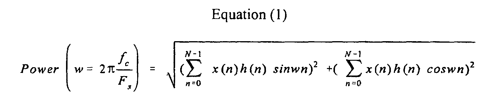
- the sampled signal is filtered to look for any of the eight predefined row or column frequencies. This is done by performing eight power calculations in power calculator 320 using the equation (1) below.
- the correlation filtering technique is also referred to as a modified Hilbert Transform or Discrete Fourier Transform at a single frequency.
- the variable h(n) is a set of low pass FIR coefficients with a Hamming, Kaiser or desired window function.
- the length of the window for viewing the signal x(n) may be any size. In a preferred embodiment, a length of 192 samples is the length of the window used for correlation.
- the tone filter 300 works as follows. Eight tone filters are performed on the input signal, one at each of the four row and four column DTMF frequencies defined in the standard, and a power result calculated for each of the filtering operations 310. The eight power results reflect the power of the input signal at each of those frequencies. The eight frequencies are sorted 320 in largest to smallest order. The top three are used by the tone detection algorithm 500.
- the aliasing and band pass filter system 400 assists in verifying the validity of the detected pair by calculating the power in row and column bands of the signal.
- the spectral energy accompanying the tone pair should be relatively quiet, or low in power, compared to the pair.
- an input signal x(n) is input to sampler 410 and sampled at a rate set by the clock.
- the resulting signal x'(m) is sent to row band pass filter 420 and to column band pass filter 430.
- the top three tone power results from 300 and the row and column band pass power results 400, are passed to the tone detection algorithm 500.
- the tone detection algorithm 500 is an algorithm to verify that communication standards, such as LSSGR, are met by an input signal. The algorithm checks to see if the filters that resulted in the top two power levels, TP1 and TP2, are a row and column frequency that make a DTMF digit. It will then check the third highest power level, TP3, to make sure that it and hence all the other tone powers calculated in equation 1, are well below the tone pair's power level. The algorithm checks that the power of the row tone and the column tone, that comprise the digit, is roughly equal to the power in the row band and column band respectively.
- the algorithm checks other standard requirements such as by verifying - 1) Minimum power required of top two tones; 2) Maximum power difference between top two tones; 3) Frequency deviation by comparing top two tones to their respective row and column aliasing band pass filter power result; 4) Difference between top two tones and their respective row and column band pass filter power results is in a range allowed by the standards; and 5) Tone length. If pair fails any of these tests reject the digit as invalid, otherwise it is valid.
- DTMF signaling standards clearly define how much spectral content is allowed to surround the signaling tone pair in the 4khz voice band used in telephony. Also, only one tone from the row band and one tone from the column band is allowed in DTMF signaling. Further, the power of the entire spectral content, other than the tone pair, has to be least 10db below the tone pair. The frequency of the tone pair must be within ⁇ 3.5% of the definition. All these requirements are checked by the detection algorithm 500. The detection algorithm also verifies the minimum tone pair on and off duration requirements. The power calculated in the row 440 and column band 450 are compared to the power of the signals at the frequencies suspected to be the dual tone pair.
- the present invention aids in calculating the power output by the band pass filters 440 and 450 and accounting for the spectral energy outside of the DTMF row and column band to improve the tone detection, since speech and music have significant power in the entire 4khz voice band.
- the present invention uses aliasing band pass filters as filters 420 and 430. These filters perform the calculation using equation (2) below.
- the coefficients b K define the FIR band pass filter coefficients.
- the variable m represents the length of the window for viewing x(n).
- the order of the FIR filter, K can be chosen based on the desired band pass filter response curve. In a preferred embodiment, the order K was chosen to be 29.
- Figure 5 shows the response of the aliasing band pass filters for filtering signals sampled at one-half of the Nyquist frequency.
- the column band pass filter calculates power in the input signal at all the frequencies from roughly 1100hz to 1900hz including the four defined column frequencies.
- the resulting root mean square (rms) power calculation will contain power from frequencies aliased from the 2khz to 4khz range of the voice band.
- Figure 7(a) shows the frequency characteristics of an input signal x(n) that contains two tones at the DTMF frequencies of 697hz and 1209hz and an interfering tone at 2400hz.
- the input signal is resampled to create signal x'(m) (step 620), which is shown in Figure 8(a). Notice that the 2400hz tone is now aliased into the DTMF band at approximately 1600hz.
- the aliasing band pass filters filter signal x 1 (m) (step 630).
- Figures 8(b) and 8(c) show responses of the aliasing row band pass filter and the aliasing column band pass filter, respectively.
- the tone detection algorithm analyzes the power levels of the signal output by the band pass filter and the top three tone filters to validate or reject frequency pairs (step 640).
- a comparison of the 697hz tone filter power result shown in Figure 7(b) with the aliasing row band pass filter power result shown Figure 8(b) illustrates no excess power.
- the aliasing column band pass filter power comparison result for this example will show about 2 to 3db additional power in the aliasing column band filter result shown in Figure 8(c) above the 1209hz tone filter power result shown in Figure 7(c).
- the tone detection algorithm 640 will reject this example as an invalid DTMF tone due to the excess power seen in the column band. Speech noise and music will not always so clearly show an interfering tone. But the overall excess spectral energy found around simulated digits will be accounted for in the aliasing band pass filter power results and aid in rejection.
- the present invention is preferably used in a tone receiver designed to meet the LSSGR requirements, as shown in Table 2, and comply with the ITU/CCITT recommendations Q.24.
- LSSGR is applicable in the North American telephony market while ITU/CCITT recommendations are for the international telephony market.
- the tone detector of the present invention allows for the accurate rejection of invalid dual tone pairs well beyond the minimum accepted criteria defined by standards.
Description
| Row/ | 1 | 2 | 3 | 4 |
| 1 | 1 | 2 | 3 | |
| 2 | 4 | 5 | 6 | |
| 3 852Hz | 7 | 8 | 9 | |
| 4 941Hz | * | 0 | # | D |
| LSSGR TR-NWT-000506 | Echo | Accept | |
| LSSGR TR-NPL-000275 | |||
| AT&T recommendations from Notes on the Network Section | |||
| Power: | Accept > = -25 dbm/freq | Single Frequency Deviation | -1.5% < Accept < + 1.5% -3.5% < Reject < +3.5% |
| Reject < -55 dbm/freq | Other Specifications | ||
| Twist: | -8 dbr < Accept < +4 dbr | Talk_off rejection from TR-TSY-000763 | |
| Tone On Duration: | Accept >= 40 ms Reject < 23 ms Minimum cycle time = 93 ms | Gaussian/Impulse noise rejection Third frequency rejection Power line noise rejection | |
| Interdigit Gap: | Accept > = 40 ms No minimum reject interval Odbm is defined as lmW through a 600ohm load | Registration in the presence of dial tone Rejection of short breaks in tone |
In The Drawings,

| TP1 = 25dbm | highest tone filter power result |
| TP2 = 25dbm | second highest tone filter power result |
| TP3 = very small (<-50dbm) | third highest tone filter power result |
| RBPF = -25dbm | row band pass filter power result |
| CBPF = -22dbm | column band pass filter power result |
Claims (15)
- A system for detecting a dual tone pair, comprising:means for sampling an input signal at a first sampling rate;means for respectively filtering the sampled signal at a plurality of frequencies;means for determining a power of the sampled signal at each of the plurality of frequencies characterised by:means (320) for sorting the frequencies in descending power levels;means for resampling the input signal at a second sampling rate, said second sampling rate being slower than the first sampling rate;aliasing band pass filters (400) for filtering the resampled signals in two defined bands;means (310) for calculating a power of the filtered resampled signal in the row and column bands;means for comparing the power ofthe band pass filtered resampled signal to the power of the sorted top three tone filter power results, and a tone detector (500) arranged to receive the sorted top three tone filter power results (300) and the output (400) of the aliasing band pass filter and further arranged to compare the power of the band pass filtered resampled signal to the power of the sorted top three tone filter power results.
- The system according to claim 1 wherein the first sampling rate is set at a Nyquist frequency.
- The system according to claim 1 wherein the second sampling rate is one-half of a Nyquist frequency.
- The system according to claim 1 wherein the means for respectively filtering the sampled signal includes
means for filtering the sampled signal at four predefined row frequencies; and
means for filtering the sampled signal at four predefined column frequencies. - The system according to claim 1 further including means for sorting eight tone filter power results and presenting the top three power results along with the band pass power results to the tone detector.
- The system according to claim 5 wherein the tone detection algorithm verifies the requirements defined by telecommunication standards.
- The system according to claim 1 wherein the means for determining tone filter power includes means for performing the following calculation:

- The system according to claim 1 wherein the aliasing band pass filters include means for calculating power according to the following equation:

- A method of detecting a dual tone pair, comprising:sampling (600) an input signal at a first sampling rate;respectively filtering (610) the sampled signal at a plurality of frequencies;determining a power of the sampled signal at each of the plurality of frequencies; characterised bysorting the plurality of frequencies in descending order;selecting the top three power result frequencies;resampling (620) the input signal at a second sampling rate, said second sampling rate being slower than the first sampling rate;filtering (630) the resampled signals at the row and column band frequencies;calculating a power of the filtered resampled signal in the row and column bands; andpresenting (640) the top three power result tone frequencies and the row and column aliasing band pass filters to a tone detection algorithm to review power levels, tone detection algorithm being arranged to use the top three power results and row and column aliaising band pass filter results to verify the dual tone pair or reject the pair as a simulated digit.
- The method according to claim 9 wherein the step of sampling at a first sampling rate includes the step of sampling at a Nyquist frequency.
- The method according to claim 9 wherein the step of resampling at a second sampling rate includes the step of sampling at one-half of a Nyquist frequency.
- The method according to claim 9 wherein the step of respectively filtering the sampled signal includes the steps of
filtering the sampled signal at four predefined row frequencies; and
filtering the sampled signal at four predefined column frequencies. - The method according to claim 9 wherein the simulated digit is verified according to requirements defined by telecommunication standards.
- The method according to claim 9 wherein the step of determining includes the step of performing the following calculation:

- The method according to claim 9 wherein the step of filtering the resampled signal includes the step of calculating power according to the following equation:

Applications Claiming Priority (3)
| Application Number | Priority Date | Filing Date | Title |
|---|---|---|---|
| US873875 | 1997-06-12 | ||
| US08/873,875 US5995557A (en) | 1997-06-12 | 1997-06-12 | Tone detection with aliasing bandpass filters |
| PCT/CA1998/000550 WO1998057502A1 (en) | 1997-06-12 | 1998-06-03 | Tone detection with aliasing bandpass filters |
Publications (2)
| Publication Number | Publication Date |
|---|---|
| EP0988758A1 EP0988758A1 (en) | 2000-03-29 |
| EP0988758B1 true EP0988758B1 (en) | 2003-12-10 |
Family
ID=25362505
Family Applications (1)
| Application Number | Title | Priority Date | Filing Date |
|---|---|---|---|
| EP98925358A Expired - Lifetime EP0988758B1 (en) | 1997-06-12 | 1998-06-03 | Tone detection with aliasing bandpass filters |
Country Status (5)
| Country | Link |
|---|---|
| US (1) | US5995557A (en) |
| EP (1) | EP0988758B1 (en) |
| CA (1) | CA2293280A1 (en) |
| DE (1) | DE69820440T2 (en) |
| WO (1) | WO1998057502A1 (en) |
Families Citing this family (9)
| Publication number | Priority date | Publication date | Assignee | Title |
|---|---|---|---|---|
| US6393124B1 (en) * | 1997-04-15 | 2002-05-21 | Virata Corporation | CPE alert signal tone detector |
| US6370244B1 (en) * | 1998-04-03 | 2002-04-09 | Board Of Regents Of The University Of Texas System | Efficient digital ITU-compliant zero-buffering DTMF detection using the non-uniform discrete fourier transform |
| AU3477999A (en) * | 1998-04-07 | 1999-10-25 | 3Com Corporation | Controlled aliasing to simplify service selection |
| US6665350B1 (en) * | 1998-09-25 | 2003-12-16 | Legerity, Inc. | Method and system for improved analog signal detection |
| US6661848B1 (en) | 1998-09-25 | 2003-12-09 | Intel Corporation | Integrated audio and modem device |
| US6711205B1 (en) | 1998-09-25 | 2004-03-23 | Intel Corporation | Tone detector for use in a modem |
| JP3721003B2 (en) * | 1999-04-01 | 2005-11-30 | 沖電気工業株式会社 | Tone signal detection method and tone signal detector |
| US7426235B1 (en) * | 2004-10-15 | 2008-09-16 | Xilinx, Inc. | Method of adaptive equalization for high-speed NRZ and multi-level signal data communications |
| US9058209B2 (en) * | 2012-04-09 | 2015-06-16 | Intel Corporation | Methods and apparatus for efficient tone detection |
Family Cites Families (15)
| Publication number | Priority date | Publication date | Assignee | Title |
|---|---|---|---|---|
| US4395595A (en) * | 1980-04-23 | 1983-07-26 | Nippon Electric Co., Ltd. | Digital pushbutton signalling receiver |
| DE3275052D1 (en) * | 1982-06-25 | 1987-02-12 | Ibm | Tone detector and multifrequency receiver using this detector |
| CA1289281C (en) * | 1988-05-05 | 1991-09-17 | Jerry Stroobach | Digital dtmf tone detector |
| US4990848A (en) * | 1988-06-13 | 1991-02-05 | Texas Instruments Incorporated | DTMF receiver |
| US5138569A (en) * | 1989-12-18 | 1992-08-11 | Codex Corporation | Dual tone multi-frequency detector |
| US4989169A (en) * | 1990-02-05 | 1991-01-29 | Motorola, Inc. | Digital tone detector using a ratio of two demodulators of differing frequency |
| US5257309A (en) * | 1990-12-11 | 1993-10-26 | Octel Communications Corporation | Dual tone multifrequency signal detection and identification methods and apparatus |
| US5163050A (en) * | 1991-01-23 | 1992-11-10 | Digital Sound Corporation | Configurable parameter dtmf detector |
| US5392348A (en) * | 1991-11-25 | 1995-02-21 | Motorola, Inc. | DTMF detection having sample rate decimation and adaptive tone detection |
| US5321745A (en) * | 1992-05-26 | 1994-06-14 | Vmx, Inc. | Adaptive efficient single/dual tone decoder apparatus and method for identifying call-progression signals |
| EP0579927A2 (en) * | 1992-06-24 | 1994-01-26 | Siemens Rolm Communications Inc. (a Delaware corp.) | DTMF signal detection for voice processing equipment |
| US5333191A (en) * | 1993-04-22 | 1994-07-26 | Interdigital Technology Corporation | Detection of multifrequency tone signals |
| US5619564A (en) * | 1995-05-31 | 1997-04-08 | Lucent Technologies Inc. | Tone detector with improved performance in the presence of speech |
| US5734577A (en) * | 1996-03-11 | 1998-03-31 | Lucent Technologies Inc. | Adaptive IIR multitone detector |
| US5809133A (en) * | 1996-05-24 | 1998-09-15 | Advanced Micro Devices, Inc. | DTMF detector system and method which performs frequency domain energy calculations with improved performance |
-
1997
- 1997-06-12 US US08/873,875 patent/US5995557A/en not_active Expired - Lifetime
-
1998
- 1998-06-03 WO PCT/CA1998/000550 patent/WO1998057502A1/en active IP Right Grant
- 1998-06-03 EP EP98925358A patent/EP0988758B1/en not_active Expired - Lifetime
- 1998-06-03 CA CA002293280A patent/CA2293280A1/en not_active Abandoned
- 1998-06-03 DE DE69820440T patent/DE69820440T2/en not_active Expired - Fee Related
Also Published As
| Publication number | Publication date |
|---|---|
| WO1998057502A1 (en) | 1998-12-17 |
| US5995557A (en) | 1999-11-30 |
| CA2293280A1 (en) | 1998-12-17 |
| DE69820440T2 (en) | 2004-05-27 |
| EP0988758A1 (en) | 2000-03-29 |
| DE69820440D1 (en) | 2004-01-22 |
Similar Documents
| Publication | Publication Date | Title |
|---|---|---|
| EP0746170B1 (en) | Tone detector with improved performance in the presence of speech | |
| CA1289281C (en) | Digital dtmf tone detector | |
| EP0547373B1 (en) | A circuit and method for dual-tone multifrequency detection | |
| JP3027047B2 (en) | DTMF signal detection apparatus and method | |
| EP0570097A1 (en) | Apparatus and robust method for detecting tones | |
| EP0622964B1 (en) | Voice activity detection method and apparatus using the same | |
| US5163050A (en) | Configurable parameter dtmf detector | |
| EP0632666A1 (en) | Dual tone detector operable in the presence of speech or background noise and method therefor | |
| EP0988758B1 (en) | Tone detection with aliasing bandpass filters | |
| US6782095B1 (en) | Method and apparatus for performing spectral processing in tone detection | |
| WO1996025825B1 (en) | Method and structure for detecting a customer premises equipment alerting signal | |
| US5426696A (en) | Method of improving receiver sensitivity and speech immunity with DTMF-reception | |
| EP0347038B1 (en) | DTMF receiver | |
| US6229889B1 (en) | Robust signaling tone frequency measurement | |
| CA1200031A (en) | Adaptive signal receiving method and apparatus | |
| US6115464A (en) | Method and system for distinguishing valid DTMF signals from spurious DTMF noise | |
| US6587559B1 (en) | Cross-frame dual tone multifrequency detector | |
| US6393124B1 (en) | CPE alert signal tone detector | |
| US20020097860A1 (en) | Frequency error detection methods and systems using the same | |
| US6574334B1 (en) | Efficient dynamic energy thresholding in multiple-tone multiple frequency detectors | |
| US7023981B2 (en) | Method and apparatus for signal detection | |
| WO2000030325A1 (en) | Method and apparatus for detecting signalling tones | |
| GB2430832A (en) | Dual-tone multiple frequency (dtmf) symbol detection | |
| Khalesehosseini et al. | 60-channel dual tone multi-frequency signaling receiver based on Goertzel algorithm on single 100MIPS TMS320C54 DSP platform | |
| JP2853842B2 (en) | DTMF signal judgment circuit |
Legal Events
| Date | Code | Title | Description |
|---|---|---|---|
| PUAI | Public reference made under article 153(3) epc to a published international application that has entered the european phase |
Free format text: ORIGINAL CODE: 0009012 |
|
| 17P | Request for examination filed |
Effective date: 20000112 |
|
| AK | Designated contracting states |
Kind code of ref document: A1 Designated state(s): DE FR GB |
|
| RAP1 | Party data changed (applicant data changed or rights of an application transferred) |
Owner name: NORTEL NETWORKS LIMITED |
|
| 17Q | First examination report despatched |
Effective date: 20020930 |
|
| GRAH | Despatch of communication of intention to grant a patent |
Free format text: ORIGINAL CODE: EPIDOS IGRA |
|
| GRAS | Grant fee paid |
Free format text: ORIGINAL CODE: EPIDOSNIGR3 |
|
| RAP1 | Party data changed (applicant data changed or rights of an application transferred) |
Owner name: NORTEL NETWORKS LIMITED |
|
| GRAA | (expected) grant |
Free format text: ORIGINAL CODE: 0009210 |
|
| AK | Designated contracting states |
Kind code of ref document: B1 Designated state(s): DE FR GB |
|
| REG | Reference to a national code |
Ref country code: GB Ref legal event code: FG4D |
|
| REF | Corresponds to: |
Ref document number: 69820440 Country of ref document: DE Date of ref document: 20040122 Kind code of ref document: P |
|
| PG25 | Lapsed in a contracting state [announced via postgrant information from national office to epo] |
Ref country code: GB Free format text: LAPSE BECAUSE OF NON-PAYMENT OF DUE FEES Effective date: 20040603 |
|
| ET | Fr: translation filed | ||
| PLBE | No opposition filed within time limit |
Free format text: ORIGINAL CODE: 0009261 |
|
| STAA | Information on the status of an ep patent application or granted ep patent |
Free format text: STATUS: NO OPPOSITION FILED WITHIN TIME LIMIT |
|
| 26N | No opposition filed |
Effective date: 20040913 |
|
| PG25 | Lapsed in a contracting state [announced via postgrant information from national office to epo] |
Ref country code: DE Free format text: LAPSE BECAUSE OF NON-PAYMENT OF DUE FEES Effective date: 20050101 |
|
| GBPC | Gb: european patent ceased through non-payment of renewal fee |
Effective date: 20040603 |
|
| PG25 | Lapsed in a contracting state [announced via postgrant information from national office to epo] |
Ref country code: FR Free format text: LAPSE BECAUSE OF NON-PAYMENT OF DUE FEES Effective date: 20050228 |
|
| REG | Reference to a national code |
Ref country code: FR Ref legal event code: ST |