EP0988477B1 - Method and device for the power shiftable change-over of a hydrostatic vehicle drive of a mobile construction machine - Google Patents
Method and device for the power shiftable change-over of a hydrostatic vehicle drive of a mobile construction machine Download PDFInfo
- Publication number
- EP0988477B1 EP0988477B1 EP99908862A EP99908862A EP0988477B1 EP 0988477 B1 EP0988477 B1 EP 0988477B1 EP 99908862 A EP99908862 A EP 99908862A EP 99908862 A EP99908862 A EP 99908862A EP 0988477 B1 EP0988477 B1 EP 0988477B1
- Authority
- EP
- European Patent Office
- Prior art keywords
- switch
- pressure
- frequency
- changeover
- power
- Prior art date
- Legal status (The legal status is an assumption and is not a legal conclusion. Google has not performed a legal analysis and makes no representation as to the accuracy of the status listed.)
- Expired - Lifetime
Links
Images

Classifications
-
- F—MECHANICAL ENGINEERING; LIGHTING; HEATING; WEAPONS; BLASTING
- F16—ENGINEERING ELEMENTS AND UNITS; GENERAL MEASURES FOR PRODUCING AND MAINTAINING EFFECTIVE FUNCTIONING OF MACHINES OR INSTALLATIONS; THERMAL INSULATION IN GENERAL
- F16H—GEARING
- F16H61/00—Control functions within control units of change-speed- or reversing-gearings for conveying rotary motion ; Control of exclusively fluid gearing, friction gearing, gearings with endless flexible members or other particular types of gearing
- F16H61/38—Control of exclusively fluid gearing
- F16H61/40—Control of exclusively fluid gearing hydrostatic
- F16H61/42—Control of exclusively fluid gearing hydrostatic involving adjustment of a pump or motor with adjustable output or capacity
- F16H61/423—Motor capacity control by fluid pressure control means
-
- E—FIXED CONSTRUCTIONS
- E02—HYDRAULIC ENGINEERING; FOUNDATIONS; SOIL SHIFTING
- E02F—DREDGING; SOIL-SHIFTING
- E02F9/00—Component parts of dredgers or soil-shifting machines, not restricted to one of the kinds covered by groups E02F3/00 - E02F7/00
- E02F9/20—Drives; Control devices
- E02F9/22—Hydraulic or pneumatic drives
- E02F9/2278—Hydraulic circuits
- E02F9/2296—Systems with a variable displacement pump
-
- F—MECHANICAL ENGINEERING; LIGHTING; HEATING; WEAPONS; BLASTING
- F16—ENGINEERING ELEMENTS AND UNITS; GENERAL MEASURES FOR PRODUCING AND MAINTAINING EFFECTIVE FUNCTIONING OF MACHINES OR INSTALLATIONS; THERMAL INSULATION IN GENERAL
- F16H—GEARING
- F16H47/00—Combinations of mechanical gearing with fluid clutches or fluid gearing
- F16H47/02—Combinations of mechanical gearing with fluid clutches or fluid gearing the fluid gearing being of the volumetric type
-
- F—MECHANICAL ENGINEERING; LIGHTING; HEATING; WEAPONS; BLASTING
- F16—ENGINEERING ELEMENTS AND UNITS; GENERAL MEASURES FOR PRODUCING AND MAINTAINING EFFECTIVE FUNCTIONING OF MACHINES OR INSTALLATIONS; THERMAL INSULATION IN GENERAL
- F16H—GEARING
- F16H59/00—Control inputs to control units of change-speed-, or reversing-gearings for conveying rotary motion
- F16H59/68—Inputs being a function of gearing status
- F16H2059/6838—Sensing gearing status of hydrostatic transmissions
- F16H2059/6861—Sensing gearing status of hydrostatic transmissions the pressures, e.g. high, low or differential pressures
-
- F—MECHANICAL ENGINEERING; LIGHTING; HEATING; WEAPONS; BLASTING
- F16—ENGINEERING ELEMENTS AND UNITS; GENERAL MEASURES FOR PRODUCING AND MAINTAINING EFFECTIVE FUNCTIONING OF MACHINES OR INSTALLATIONS; THERMAL INSULATION IN GENERAL
- F16H—GEARING
- F16H59/00—Control inputs to control units of change-speed-, or reversing-gearings for conveying rotary motion
- F16H59/14—Inputs being a function of torque or torque demand
- F16H59/26—Inputs being a function of torque or torque demand dependent on pressure
-
- F—MECHANICAL ENGINEERING; LIGHTING; HEATING; WEAPONS; BLASTING
- F16—ENGINEERING ELEMENTS AND UNITS; GENERAL MEASURES FOR PRODUCING AND MAINTAINING EFFECTIVE FUNCTIONING OF MACHINES OR INSTALLATIONS; THERMAL INSULATION IN GENERAL
- F16H—GEARING
- F16H59/00—Control inputs to control units of change-speed-, or reversing-gearings for conveying rotary motion
- F16H59/36—Inputs being a function of speed
- F16H59/38—Inputs being a function of speed of gearing elements
- F16H59/40—Output shaft speed
-
- F—MECHANICAL ENGINEERING; LIGHTING; HEATING; WEAPONS; BLASTING
- F16—ENGINEERING ELEMENTS AND UNITS; GENERAL MEASURES FOR PRODUCING AND MAINTAINING EFFECTIVE FUNCTIONING OF MACHINES OR INSTALLATIONS; THERMAL INSULATION IN GENERAL
- F16H—GEARING
- F16H61/00—Control functions within control units of change-speed- or reversing-gearings for conveying rotary motion ; Control of exclusively fluid gearing, friction gearing, gearings with endless flexible members or other particular types of gearing
- F16H61/02—Control functions within control units of change-speed- or reversing-gearings for conveying rotary motion ; Control of exclusively fluid gearing, friction gearing, gearings with endless flexible members or other particular types of gearing characterised by the signals used
- F16H61/0202—Control functions within control units of change-speed- or reversing-gearings for conveying rotary motion ; Control of exclusively fluid gearing, friction gearing, gearings with endless flexible members or other particular types of gearing characterised by the signals used the signals being electric
- F16H61/0204—Control functions within control units of change-speed- or reversing-gearings for conveying rotary motion ; Control of exclusively fluid gearing, friction gearing, gearings with endless flexible members or other particular types of gearing characterised by the signals used the signals being electric for gearshift control, e.g. control functions for performing shifting or generation of shift signal
- F16H61/0213—Control functions within control units of change-speed- or reversing-gearings for conveying rotary motion ; Control of exclusively fluid gearing, friction gearing, gearings with endless flexible members or other particular types of gearing characterised by the signals used the signals being electric for gearshift control, e.g. control functions for performing shifting or generation of shift signal characterised by the method for generating shift signals
-
- F—MECHANICAL ENGINEERING; LIGHTING; HEATING; WEAPONS; BLASTING
- F16—ENGINEERING ELEMENTS AND UNITS; GENERAL MEASURES FOR PRODUCING AND MAINTAINING EFFECTIVE FUNCTIONING OF MACHINES OR INSTALLATIONS; THERMAL INSULATION IN GENERAL
- F16H—GEARING
- F16H61/00—Control functions within control units of change-speed- or reversing-gearings for conveying rotary motion ; Control of exclusively fluid gearing, friction gearing, gearings with endless flexible members or other particular types of gearing
- F16H61/16—Inhibiting or initiating shift during unfavourable conditions, e.g. preventing forward reverse shift at high vehicle speed, preventing engine over speed
Definitions
- the invention relates to a method and a device with the features according to the preamble of claim 1 or 9.
- DE 195 20 454 C1 from the applicant is a method and a device for load-dependent automatic switching at least one two-stage hydraulic Drive motor of a mobile construction machine known in which by operating a switch at least two with at least a switching element in operative connection Pressure switches with different hydraulic response pressures can be activated one after the other, using depending on one or the other pressure switch specified load conditions in the hydraulic Drive circuit operated changeover valve on the changeover of the traction motor from its maximum swallowing volume lowest swallowing volume and vice versa effecting valve is controlled electrically.
- This known method therefore concerns an automatic switchover of a two-stage hydraulic driving motor, however not a generic method in which a powershift transmission to be switched.
- the object of the invention is a generic method and to further develop a generic device in such a way that depending on the load between the switching stages of the Powershift transmission automatically switched over in a reliable manner can be so that the entire driving range from minimal up to maximum speed at different Drive through driving resistances without manual switching can be.
- driving safety should increase and a danger to the construction machine components during the switching process be safely avoided.
- An automatic switchover is thus according to the invention provided by the driver by actuation a switch can be activated.
- a switch can be activated.
- a relay switching element or equivalent devices creates a switching window, which, on the one hand, automatically switches to both Directions (level 1 after level 2 and level 2 after level 1) enables and on the other hand unnecessarily frequent switching prevented. Switching is dependent hydrostatic pressure in the driving circuit (maximum or Minimum value).
- the construction machine is monitored and exceeded a predetermined speed value Downshifting the powershift transmission is prevented.
- a vehicle speed proportional Frequency signal from a Evaluation unit evaluated and via a frequency-dependent Switch enables or prevents switching becomes.
- the frequency-dependent switch on the changeover valve acts.
- the frequency-dependent switch acts on an additional valve, which is arranged parallel to the changeover valve and is hydraulically linked to it.
- the driving speed the construction machine is monitored and at a standstill the construction machine automatically switches back the lowest gear of the powershift transmission takes place.
- This can also expediently be via the frequency-dependent Switches are made via which are determined whether the vehicle is stationary or not. This can an additional frequency-dependent switch is also provided become.
- that the lower response pressure of the pressure switch is set is that he has a pressure of the control pump in the area corresponds to their maximum output.
- the upper response pressure the pressure switch is set so that it is in the range of the maximum system pressure.
- the invention proposes to achieve the object stated at the outset also a device with the features of claim 9 before.
- the switch is usually located in the cab the construction machine and makes the choice between manual and automatic switching.
- the one with the pressure switches connected switching element can preferably be used as a relay be trained.
- the frequency-dependent switch is advantageous in operative connection with the changeover valve.
- you can but it should also be provided that the frequency-dependent Switch with an additional valve in operative connection is arranged in parallel to the switching valve and with this is hydraulically linked.
- the frequency-dependent Switch has a first output that a relay with the changeover valve in operative connection stands.
- this relay it is possible to control the frequency and thus speed-dependent switching only when reducing the speed, i.e. when downshifting of the powershift transmission to take effect to avoid a load-independent upshift. This ensures that the upshift only depends on the load he follows.
- the frequency-dependent Switch has a second output that over another relay with the changeover valve in operative connection stands, with the further relay between the switching element and the switch and the relay arranged is.
- the frequency-dependent switch can in the above Way have two outputs, alternatively can be provided that the frequency-dependent switch of two separate switches, each with an output is.
- the pressure switch, the switching element, the frequency-dependent switch and the relays as common electronic, hydraulic or pneumatic Switching logic are formed.
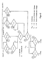
- An exemplary hydrostatic drive a mobile construction machine generally has one 2, 10 designated driving circuit and a connected to it Powershift transmission 1, which is shown in the Embodiment is two-stage, that is, a first and has a second gear.
- the powershift transmission 1 has two output axes that drive the Steering axis and as a drive for the rigid axis of the construction machine serve.
- the driving circuit 2, 10 has the usual elements that not explained in detail at this point.
- a hydrostatic control pump is not shown, which is only indicated by an arrow 10.
- in the Drive circuit 2, 10 is a hydraulic shuttle valve 11 arranged.
- This hydraulic shuttle valve 11 About this hydraulic shuttle valve 11 are to the Driving circuit two parallel pressure switches 3 and 4 connected, which serve as switching elements and different have hydraulic response pressures. Both pressure switches 3 and 4 are designed as openers.
- the pressure switch 3 has a smaller hydraulic response pressure on than the pressure switch 4.
- Both pressure switches 3 and 4 are with a preferably formed by a relay Switching element 5 connected and with a switch 7, which is arranged in the cab of the construction machine.
- This switching arrangement acts on a 4/2-way valve that hereinafter referred to as changeover valve 6.
- changeover valve 6 is a changeover of the powershift transmission 1 from first gear to second gear or vice versa.
- the switching arrangement also has a frequency-dependent Switch 9 on, which is connected to an initiator 8 is in the area of the rigid axis of the drive the construction machine is arranged or on another output side Location of the transmission can be arranged.
- the frequency-dependent switch 9 has two outputs, the first output via a relay 12 with the switching valve 6 is connected.
- the second output of the frequency dependent Switch 9 is connected via a relay 13 the switching valve 6 connected, the relay 13 between the switch valve 6 and the switch 7 in the cab as well as the relay 12 and the frequency-dependent Switch 9 is arranged.
- the function of these components will be described in more detail below.
- this is electrical pilot operated changeover valve 6 so that the first Gear is switched. They are in this state Pressure switches 3 and 4 closed. With the switch 7 in The driver's cab can choose between automatic in the closed position and fixed first gear in the open position.
- the switch 9 works in its first switching output as a break contact if a specified Frequency signal dependent on vehicle speed by initiator 8 falls below a limit. Thereby can be used in fast moving mobile construction machines dangerous switching from higher to lower Prevent gear at impermissibly high driving speeds.
- the relay 12 In series with the first output of the frequency dependent Switch 9 is the relay 12, which is electrically connected is that switching from the first to the second Gear only depending on the load pressure in the driving circuit and is not speed-dependent.
- the hydraulic motor of the driving circuit 2 is swung out to Q max during the pressure increase (internal control in the driving circuit 2, 10), while the pump 10 is regulated back to a smaller delivery rate at its maximum power hyperbola.
- the transmission output torque can due to a higher working pressure in the driving circuit 2, 10 and a larger absorption volume of the hydraulic motor following the driving force hyperbola (maximum power) increased to the maximum torque (gearbox output) be, whereby the driving speed decreases accordingly.
- the pressure switch 3 is open at higher pressure. This means that no signal on the switching element 5 and the Switch 7 is given. At low pressure the Pressure switch 3 closed and there is a signal the switching element 5 and the switch 7.
- the pressure switch 4 is closed below the maximum pressure P max and there is a voltage on the switching element 5.
- the shift element 5 is in the first gear of the powershift transmission 1 open and closed in second gear.
- the switch 7 can be opened or closed manually become. If it is open, the first gear is fixed, it is closed, the first or second gear is automatically connected.
- the switch 9 has in the illustrated embodiment two outputs if the first output 9a (switching window) is open, the voltage is interrupted, there is a Circuit according to the logic of elements 3, 4, 5 and 7. Is the first output closed, a voltage is applied to that Relay 12 passed.
- the relay 12 is open in the first gear and in the second Aisle closed.
- the first gear switched and in the closed state is the first or the second gear, depending on the position of the Elements 12, 7 and 5.
Abstract
Description
Die Erfindung betrifft ein Verfahren bzw. eine Einrichtung
mit den Merkmalen gemäß Oberbegriff des Patentanspruchs 1
bzw. 9.The invention relates to a method and a device
with the features according to the preamble of
Es sind Mobilbagger oder vergleichbare Baumaschinen entsprechend den Merkmalen des jeweiligen Oberbegriffs mit manuell schaltbaren zweistufigen Stirnradgetrieben in Verbindung mit einem hydrostatischen Fahrantrieb oder mit einem rein hydrostatischen Fahrantrieb (Hydrotransmatik) bekannt. Das Schalten geschieht entweder durch manuellen Eingriff des Fahrers auf die Getriebeschaltung oder durch automatische oder manuelle Schaltvorgänge im hydrostatischen Fahrantrieb.They are mobile excavators or comparable construction machines according to the characteristics of the respective generic term manually switchable two - stage spur gear in Connection with a hydrostatic drive or with a purely hydrostatic drive (hydrotransmatics) known. Switching is done either manually Intervention of the driver on the gear shift or by automatic or manual switching operations in hydrostatic Traction drive.
Beim manuellen Schalten des Getriebes ist nicht auszuschließen, daß der Fahrantrieb nicht in der optimalen Schaltstufe betrieben wird. Dies kann im ungünstigsten Fall sogar die Fahrsicherheit und auch die Komponenten der Baumaschine gefährden, beispielsweise, wenn ein Umschalten in einen niedrigen Gang bei zu hoher Fahrgeschwindigkeit erfolgt.When switching the transmission manually, it cannot be ruled out that the travel drive is not in the optimal Switching stage is operated. This can be the worst Case even driving safety and also the components endanger the construction machine, for example, when switching in a low gear when the driving speed is too high he follows.
Aus DE 195 20 454 C1 der Anmelderin ist ein Verfahren und eine Einrichtung zur lastabhängigen automatischen Umschaltung wenigstens eines zweistufigen hydraulischen Fahrmotors einer mobilen Baumaschine bekannt, bei dem durch Betätigung eines Schalters mindestens zwei mit mindestens einem Schaltelement in Wirkverbindung stehende Druckschalter mit unterschiedlichen hydraulischen Ansprechdrücken nacheinander aktiviert werden, wobei über das von dem einen oder dem anderen Druckschalter in Abhängigkeit vorgegebener Lastzustände im hydraulischen Fahrkreis betätigte Umschaltventil ein die Umschaltung des Fahrmotors von seinem größten Schluckvolumen auf sein geringstes Schluckvolumen und umgekehrt bewirkendes Ventil elektrisch angesteuert wird. Dieses bekannte Verfahren betrifft somit eine automatische Umschaltung eines zweistufigen hyraulischen Fahrmotors, betrifft jedoch kein gattungsgemäßes Verfahren, bei dem ein Lastschaltgetriebe umgeschaltet werden soll.DE 195 20 454 C1 from the applicant is a method and a device for load-dependent automatic switching at least one two-stage hydraulic Drive motor of a mobile construction machine known in which by operating a switch at least two with at least a switching element in operative connection Pressure switches with different hydraulic response pressures can be activated one after the other, using depending on one or the other pressure switch specified load conditions in the hydraulic Drive circuit operated changeover valve on the changeover of the traction motor from its maximum swallowing volume lowest swallowing volume and vice versa effecting valve is controlled electrically. This known method therefore concerns an automatic switchover of a two-stage hydraulic driving motor, however not a generic method in which a powershift transmission to be switched.
Aufgabe der Erfindung ist es, ein gattungsgemäßes Verfahren und eine gattungsgemäße Einrichtung derart weiterzubilden, daß lastabhängig zwischen den Schaltstufen des Lastschaltgetriebes betriebssicher automatisch umgeschaltet werden kann, so daß der gesamte Fahrbereich von Minimal- bis Höchstgeschwindigkeit bei unterschiedlichen Fahrwiderständen ohne manuelles Umschalten durchfahren werden kann. Außerdem soll die Fahrsicherheit erhöht und eine Gefährdung der Baumaschinenkomponenten beim Schaltvorgang sicher vermieden werden.The object of the invention is a generic method and to further develop a generic device in such a way that depending on the load between the switching stages of the Powershift transmission automatically switched over in a reliable manner can be so that the entire driving range from minimal up to maximum speed at different Drive through driving resistances without manual switching can be. In addition, driving safety should increase and a danger to the construction machine components during the switching process be safely avoided.
Diese Aufgabe wird mit einem Verfahren der eingangs bezeichneten
Art erfindungsgemäß durch die kennzeichnenden
Merkmale des Patentanspruchs 1 gelöst. This task is carried out using a method of the type mentioned at the beginning
Kind according to the invention by the characteristic
Features of
Erfindungsgemäß wird somit eine automatische Umschaltung
zur Verfügung gestellt, die vom Fahrer durch Betätigung
eines Schalters aktivierbar ist. Dabei wird mit Hilfe von
zwei Druckschaltern und einem Relais (Schaltelement) oder
gleichwirkenden Einrichtungen ein Schaltfenster erzeugt,
welches zum einen das automatische Umschalten in beide
Richtungen (Stufe 1 nach Stufe 2 und Stufe 2 nach Stufe
1) ermöglicht und andererseits unnötig häufiges Umschalten
verhindert. Das Umschalten erfolgt in Abhängigkeit
vom hydrostatischen Druck im Fahrkreis (Maximal- oder
Minimalwert).An automatic switchover is thus according to the invention
provided by the driver by actuation
a switch can be activated. With the help of
two pressure switches and a relay (switching element) or
equivalent devices creates a switching window,
which, on the one hand, automatically switches to both
Directions (
Zur Erhöhung der Fahrsicherheit und der Sicherheit der Maschinenkomponenten beim Umschalten ist erfindungsgemäß vorgesehen, daß die Fahrgeschwindigkeit der Baumaschine überwacht und bei Überschreiten eines vorgegebenen Geschwindigkeitswertes ein Zurückschalten des Lastschaltgetriebes verhindert wird. Dies läßt sich besonders vorteilhaft dadurch erreichen, daß zur Überwachung der Fahrgeschwindigkeit ein fahrgeschwindigkeitsproportionales Frequenzsignal von einer Auswerteeinheit bewertet und über einen frequenzabhängigen Schalter das Umschalten ermöglicht oder verhindert wird.To increase driving safety and the safety of the Machine components when switching According to the invention provided that the driving speed the construction machine is monitored and exceeded a predetermined speed value Downshifting the powershift transmission is prevented. This can be achieved particularly advantageously by that to monitor the vehicle speed a vehicle speed proportional Frequency signal from a Evaluation unit evaluated and via a frequency-dependent Switch enables or prevents switching becomes.
Ein unproblematisches Umschalten in eine niedrige Schaltstufe ist deshalb immer nur dann möglich, wenn die Fahrgeschwindigkeit der Baumaschine dies unproblematisch zuläßt. Dazu wird ein fahrgeschwindigkeitsproportionales Frequenzsignal (Tachometersignal) von einer entsprechenden Einheit bewertet. Nur wenn die Fahrgeschwindigkeit (Frequenz) innerhalb eines vorgegebenen Schaltfensters liegt, kann eine Umschaltung erfolgen.An unproblematic switch to a low switching level is therefore only possible if the driving speed the construction machine allows this without problems. For this, a driving speed proportional Frequency signal (tachometer signal) from a corresponding Unit rated. Only if the driving speed (Frequency) within a given switching window a switch can be made.
Vorzugsweise ist verfahrensmäßig weiterhin vorgesehen, daß der frequenzabhängige Schalter auf das Umschaltventil einwirkt. Alternativ kann auch vorgesehen sein, daß der frequenzabhängige Schalter auf ein zusätzliches Ventileinwirkt, welches parallel zum Umschaltventil angeordnet und mit diesem hydraulisch verknüpft ist.In terms of the method, it is preferably also provided that that the frequency-dependent switch on the changeover valve acts. Alternatively, it can also be provided that the frequency-dependent switch acts on an additional valve, which is arranged parallel to the changeover valve and is hydraulically linked to it.
Ferner ist vorteilhaft vorgesehen, daß das Hochschalten des Lastschaltgetriebes ausschließlich lastabhängig über die Druckschalter erfolgt. Dazu ist der frequenzabhängige Schalter über geeignete Elemente, beispielsweise Relais, mit dem Umschaltventil zu verbinden, um die frequenzabhängige Schaltung so einzurichten, daß sie nur für das Herunterschalten wirksam ist.It is also advantageously provided that the upshift of the powershift transmission only depending on the load the pressure switch is done. This is the frequency dependent Switches via suitable elements, such as relays, to connect with the changeover valve to the frequency dependent Set up circuit so that it is only for that Downshift is effective.
Weiterhin ist vorteilhaft vorgesehen, daß die Fahrgeschwindigkeit der Baumaschine überwacht und bei Stillstand der Baumaschine automatisch eine Rückschaltung in den niedrigsten Gang des Lastschaltgetriebes erfolgt. Dies kann zweckmäßigerweise ebenfalls über den frequenzabhängigen Schalter erfolgen, über den festgestellt werden kann, ob das Fahrzeug steht oder nicht. Hierzu kann auch ein zusätzlicher frequenzabhängiger Schalter vorgesehen werden.It is also advantageously provided that the driving speed the construction machine is monitored and at a standstill the construction machine automatically switches back the lowest gear of the powershift transmission takes place. This can also expediently be via the frequency-dependent Switches are made via which are determined whether the vehicle is stationary or not. This can an additional frequency-dependent switch is also provided become.
In weiterer vorteilhafter Ausgestaltung ist vorgesehen, daß der untere Ansprechdruck der Druckschalter so eingestellt wird, daß er einem Druck der Regelpumpe im Bereich ihrer maximalen Fördermenge entspricht.In a further advantageous embodiment, that the lower response pressure of the pressure switch is set is that he has a pressure of the control pump in the area corresponds to their maximum output.
Ferner ist verfahrensmäßig vorgesehen, daß der obere Ansprechdruck der Druckschalter so eingestellt wird, daß er im Bereich des maximalen Systemdruckes liegt.It is also procedurally provided that the upper response pressure the pressure switch is set so that it is in the range of the maximum system pressure.
Zur Lösung der eingangs gestellten Aufgabe schlägt die Erfindung auch eine Einrichtung mit den Merkmalen des Patentanspruchs 9 vor. The invention proposes to achieve the object stated at the outset also a device with the features of claim 9 before.
Der Schalter befindet sich üblicherweise im Fahrerhaus der Baumaschine und bewirkt die Wahl zwischen manueller und automatischer Schaltung. Das mit den Druckschaltern verbundene Schaltelement kann vorzugsweise als Relais ausgebildet sein.The switch is usually located in the cab the construction machine and makes the choice between manual and automatic switching. The one with the pressure switches connected switching element can preferably be used as a relay be trained.
Vorteilhaft steht dabei der frequenzabhängige Schalter mit dem Umschaltventil in Wirkverbindung. Alternativ kann aber auch vorgesehen sein, daß der freguenzabhängige Schalter mit einem zusätzlichen Ventil in Wirkverbindung steht, das parallel zum Umschaltventil angeordnet und mit diesem hydraulisch verknüpft ist.The frequency-dependent switch is advantageous in operative connection with the changeover valve. Alternatively, you can but it should also be provided that the frequency-dependent Switch with an additional valve in operative connection is arranged in parallel to the switching valve and with this is hydraulically linked.
Besonders vorteilhaft ist vorgesehen, daß der frequenzabhängige Schalter einen ersten Ausgang aufweist, der über ein Relais mit dem Umschaltventil in Wirkverbindung steht. Über dieses Relais ist es möglich, das frequenzund damit geschwindigkeitsabhängige Schalten nur bei Verringerung der Geschwindigkeit, d.h. beim Herunterschalten des Lastschaltgetriebes, wirksam werden zu lassen, um zu vermeiden, daß ein lastunabhängiges Hochschalten erfolgt. Damit ist gewährleistet, daß das Hochschalten nur lastabhängig erfolgt.It is particularly advantageous that the frequency-dependent Switch has a first output that a relay with the changeover valve in operative connection stands. With this relay it is possible to control the frequency and thus speed-dependent switching only when reducing the speed, i.e. when downshifting of the powershift transmission to take effect to avoid a load-independent upshift. This ensures that the upshift only depends on the load he follows.
Weiterhin ist vorteilhaft vorgesehen, daß der frequenzabhängige Schalter einen zweiten Ausgang aufweist, der über ein weiteres Relais mit dem Umschaltventil in Wirkverbindung steht, wobei das weitere Relais zwischen dem Umschaltelement und dem Schalter sowie dem Relais angeordnet ist. Durch das Vorsehen dieses weiteren Relais ist es möglich, automatisch bei Stillstand des Fahrzeuges eine Schaltung in den ersten Gang zu bewirken.It is also advantageously provided that the frequency-dependent Switch has a second output that over another relay with the changeover valve in operative connection stands, with the further relay between the switching element and the switch and the relay arranged is. By providing this additional relay it is possible, automatically when the vehicle is at a standstill To effect circuit in first gear.
Der frequenzabhängige Schalter kann in der vorbeschriebenen Weise zwei Ausgänge aufweisen, alternativ kann auch vorgesehen sein, daß der frequenzabhängige Schalter von zwei getrennten Schältern mit jeweils einem Ausgang gebildet ist.The frequency-dependent switch can in the above Way have two outputs, alternatively can be provided that the frequency-dependent switch of two separate switches, each with an output is.
Anstelle der vorbeschriebenen einzelnen Bauelemente kann auch vorgesehen sein, daß die Druckschalter, das Schaltelement, der frequenzabhängige Schalter und die Relais als gemeinsame elektronische, hydraulische oder pneumatische Schaltlogik ausgebildet sind.Instead of the individual components described above also be provided that the pressure switch, the switching element, the frequency-dependent switch and the relays as common electronic, hydraulic or pneumatic Switching logic are formed.
Die Erfindung ist nachstehend anhand der Zeichnung beispielsweise näher erläutert. Diese zeigt in:
- Fig. 1
- eine Prinzipskizze eines Funktionsplanes zur automatischen Umschaltung eines zweistufigen Lastschaltgetriebes eines hydrostatischen Fahrantriebes einer mobilen Baumaschine und
- Fig. 2
- ein Flußdiagramm zur Verdeutlichung der Schaltvorgänge.
- Fig. 1
- a schematic diagram of a function plan for the automatic switching of a two-stage powershift transmission of a hydrostatic travel drive of a mobile construction machine and
- Fig. 2
- a flowchart to illustrate the switching operations.
Ein beispielhaft dargestellter hydrostatischer Fahrantrieb
einer mobilen Baumaschine weist einen allgemein mit
2, 10 bezeichneten Fahrkreis und ein mit diesem verbundenes
Lastschaltgetriebe 1 auf, welches beim dargestellten
Ausführungsbeispiel zweistufig ist, also einen ersten und
einen zweiten Gang aufweist. Das Lastschaltgetriebe 1
weist zwei Abtriebsachsen auf, die als Antrieb für die
Lenkachse und als Antrieb für die Starrachse der Baumaschine
dienen. An exemplary hydrostatic drive
a mobile construction machine generally has one
2, 10 designated driving circuit and a connected to it
Der Fahrkreis 2, 10 weist die üblichen Elemente auf, die
im einzelnen an dieser Stelle nicht näher erläutert werden.
Nicht dargestellt ist eine hydrostatische Regelpumpe,
die nur durch einen Pfeil 10 angedeutet ist. Im
Fahrkreis 2, 10 ist ein hydraulisches Wechselventil 11
angeordnet.The
Über dieses hydraulische Wechselventil 11 sind an den
Fahrkreis zwei parallele Druckschalter 3 und 4 angeschlossen,
die als Schaltelemente dienen und unterschiedliche
hydraulische Ansprechdrücke aufweisen. Beide Druckschalter
3 und 4 sind als Öffner ausgebildet. Der Druckschalter
3 weist einen kleineren hydraulischen Ansprechdruck
auf als der Druckschalter 4. Beide Druckschalter 3
und 4 sind mit einem vorzugsweise von einem Relais gebildeten
Schaltelement 5 verbunden sowie mit einem Schalter
7, der im Fahrerhaus der Baumaschine angeordnet ist.
Diese Schaltanordnung wirkt auf ein 4/2-Wegeventil, das
nachfolgend als Umschaltventil 6 bezeichnet wird. Mit
diesem Umschaltventil 6 ist ein Umschalten des Lastschaltgetriebes
1 vom ersten Gang in den zweiten Gang
oder umgekehrt möglich.About this
Die Schaltanordnung weist darüber hinaus einen frequenzabhängigen
Schalter 9 auf, der mit einem Initiator 8 verbunden
ist, der im Bereich der Starrachse des Antriebes
der Baumaschine angeordnet ist oder an einem anderen abtriebsseitigen
Ort des Getriebes angeordnet sein kann.The switching arrangement also has a frequency-dependent
Switch 9 on, which is connected to an
Der frequenzabhängige Schalter 9 weist zwei Ausgänge auf,
wobei der erste Ausgang über ein Relais 12 mit dem Umschaltventil
6 verbunden ist. Der zweite Ausgang des frequenzabhängigen
Schalters 9 ist über ein Relais 13 mit
dem Umschaltventil 6 verbunden, wobei das Relais 13 zwischen
dem Umschaltventil 6 und dem Schalter 7 im Fahrerhaus
sowie dem Relais 12 und dem frequenzabhängigen
Schalter 9 angeordnet ist. Die Funktion dieser Bauelemente
wird nachfolgend noch näher beschrieben.The frequency-dependent switch 9 has two outputs,
the first output via a
Im dargestellten stromlosen Ruhezustand steht das elektrisch
vorgesteuerte Umschaltventil 6 so, daß der erste
Gang geschaltet ist. In diesem Zustand sind die beiden
Druckschalter 3 und 4 geschlossen. Mit dem Schalter 7 im
Fahrerhaus kann eine Wahl getroffen werden zwischen Automatik
in geschlossener Stellung und fixiertem ersten Gang
in geöffneter Position.In the currentless idle state shown, this is electrical
pilot operated
Unabhängig von der Schalterstellung 7 bewirkt das weitere
Relais 13 ein Umschalten in den ersten Gang durch Öffnen
im Stillstand der Baumaschine. Im folgenden wird der Zustand
"Automatik" beschrieben: Regardless of switch position 7, this has the
Das Anfahren aus dem Stillstand erfolgt immer im ersten
Gang, weil das im Stillstand geöffnete Relais 13 dieses
bewirkt. Bei Geschwindigkeiten größer als 0 wird lastdruckabhängig
ggf. in den 2. Gang geschaltet.Starting from standstill always takes place in the first
Gear, because the
Solange im 2. Gang ein Druck im Fahrkreis 2, 10 auftritt,
der niedriger ist als der Ansprechdruck des Druckschalters
3 sind beide Druckschalter 3 und 4 und das Schaltelement
5 geschlossen und der zweite Gang bleibt geschaltet.
Steigt der Druck im Fahrkreis 2, 10, wobei je nach
Fahrrichtung der jeweils höhere Druck im Fahrkreis über
das Wechselventil 11 an den Druckschaltern 3 und 4 anliegt,
so öffnet zuerst der Druckschalter 3, was aber
noch keine Auswirkung hat, und bei Erreichen eines entsprechend
höheren Druckes auch der Druckschalter 4. Dies
bewirkt jetzt, daß das Schaltelement 5 öffnet und damit
ein Signal zum Schalten in den ersten Gang gibt. Der
erste Gang wird allerdings durch Umschalten des Umschaltventiles
6 nur dann geschaltet, wenn auch der frequenzabhängige
Schalter 9 geöffnet ist. Der Schalter 9 arbeitet
in seinem ersten Schaltausgang als Öffner, wenn ein vorgegebenes,
fahrgeschwindigkeitsabhängiges Frequenzsignal
vom Initiator 8 einen Grenzwert unterschreitet. Dadurch
läßt sich bei schnell fahrenden mobilen Baumaschinen ein
gefährliches Umschalten vom höheren in einen niedrigen
Gang bei unzulässig hoher Fahrgeschwindigkeit verhindern. As long as there is pressure in
Gleichermaßen wird dadurch auch ein manuelles Umschalten in den ersten Gang verhindert.Likewise, this also makes manual switching prevented in the first gear.
In Reihe zu dem ersten Ausgang des frequenzabhängigen
Schalters 9 liegt das Relais 12, das so elektrisch verschaltet
ist, daß ein Umschalten vom ersten in den zweiten
Gang nur in Abhängigkeit vom Lastdruck im Fahrkreis
und nicht geschwindigkeitsabhängig erfolgt.In series with the first output of the frequency dependent
Switch 9 is the
Der Hydromotor des Fahrkreises 2 wird während des Druckanstieges
auf Qmax ausgeschwenkt (innere Regelung im Fahrkreis
2, 10), während die Pumpe 10 auf ihrer maximalen
Leistungshyperbel auf eine kleinere Fördermenge zurückgeregelt
wird.The hydraulic motor of the driving
Für die gleiche Fahrgeschwindigkeit im ersten Gang, wie vor dem Umschalten im zweiten Gang geht die Hauptpumpe (Fahren) aufgrund des fallenden hydraulischen Arbeitsdruckes wieder auf eine höhere Fördermenge und der hydrostatische Fahrmotor auf ein kleines Schluckvolumen.For the same driving speed in first gear as the main pump switches before switching to second gear (Driving) due to the falling hydraulic working pressure again to a higher flow rate and the hydrostatic Traction motor to a small swallowing volume.
Dabei fließt trotz des niedrigeren hydraulischen Arbeitsdruckes und des verringerten Schluckvolumens des Hydromotors aufgrund der geänderten Getriebeübersetzung annähernd das gleiche Getriebeabtriebsmoment zu den Achsen. It flows despite the lower hydraulic working pressure and the reduced swallowing volume of the hydraulic motor due to the changed gear ratio the same transmission output torque to the axes.
Bei weiter steigendem Fahrwiderstand kann das Getriebeabtriebsmoment
durch einen höheren Arbeitsdruck im Fahrkreis
2, 10 und ein größeres Schluckvolumen des Hydromotors
der Triebkrafthyperbel folgend (maximale Leistung)
bis zum maximalen Drehmoment (Getriebeabtrieb) gesteigert
werden, wobei die Fahrgeschwindigkeit entsprechend zurückgeht.If the driving resistance continues to increase, the transmission output torque can
due to a higher working pressure in the
Verringert sich der Fahrwiderstand und damit der Druck im
Fahrkreis wieder, so schließt als erstes der Druckschalter
4. Dies hat aber aufgrund der elektrischen Verschaltung
noch keinen Einfluß, da das Schaltelement 5 elektrisch
noch unversorgt bleibt (erster Gang bleibt geschaltet).
Erst beim Erreichen des Schaltdruckes des
Druckschalters 3 wird das Schaltelement 5 mit elektrischer
Spannung versorgt und schließt. Dies hat zur Folge,
daß das Umschaltventil 6 umschaltet und ein Schaltvorgang
in die zweite Getriebestufe (zweiter Gang) erfolgt. Die
geänderte Getriebeübersetzung bewirkt einen höheren Druck
im Fahrkreis, der wiederum eine Anpassung des Schluckvolumens
der Fahrpumpe 10 zur Folge hat. Bei weiter fallendem
Fahrwiderstand folgt der hydrostatische Fahrantrieb
der Triebkrafthyperbel bei maximaler Antriebsleistung bis
zur Höchstgeschwindigkeit.The driving resistance and thus the pressure in the vehicle are reduced
Again, the pressure switch closes first
4. But this has due to the electrical connection
still no influence, since the switching
Der vorbeschriebene Funktionsablauf ist auch im Flußdiagramm der Figur 2 dargestellt, aus dem die einzelnen Schaltbedingungen genauer zu entnehmen sind. Dabei sind dieselben Bezugszeichen wie in Figur 1 verwandt, lediglich der erste Ausgang des Schalters 9 ist mit 9a bezeichnet und der zweite Ausgang mit 9b. Die elektrische Spannung ist mit der üblichen Bezeichnung U, die Frequenz mit F und der Druck mit P bezeichnet.The functional sequence described above is also in the flow chart shown in Figure 2, from which the individual Switching conditions can be found more precisely. Are there the same reference numerals as used in Figure 1, only the first output of the switch 9 is designated 9a and the second exit with 9b. The electrical Voltage is commonly called U, the frequency with F and the pressure with P.
Aus den Figuren 1 und 2 geht für die einzelnen Elemente jeweils folgende Schaltstellung hervor:Figures 1 and 2 go for the individual elements the following switch position:
Der Druckschalter 3 ist bei höherem Druck geöffnet. Dies
bedeutet, daß kein Signal auf das Schaltelement 5 und den
Schalter 7 gegeben wird. Bei niedrigem Druck ist der
Druckschalter 3 geschlossen und es gibt ein Signal auf
das Schaltelement 5 und den Schalter 7.The
Der Druckschalter 4 ist unterhalb des Maximaldruckes Pmax
geschlossen und es liegt eine Spannung am Schaltelement 5
an.The
Das Schaltelement 5 ist im ersten Gang des Lastschaltgetriebes
1 offen und im zweiten Gang geschlossen.The
Der Schalter 7 kann manuell geöffnet oder geschlossen werden. Ist er offen, ist der erste Gang fixiert, ist er geschlossen, wird automatisch der erste oder zweite Gang geschaltet.The switch 7 can be opened or closed manually become. If it is open, the first gear is fixed, it is closed, the first or second gear is automatically connected.
Der Schalter 9 hat beim dargestellten Ausführungsbeispiel
zwei Ausgänge, wenn der erste Ausgang 9a (Schaltfenster)
offen ist, ist die Spannung unterbrochen, es erfolgt eine
Schaltung gemäß der Logik der Elemente 3, 4, 5 und 7. Ist
der erste Ausgang geschlossen, wird eine Spannung an das
Relais 12 geleitet.The switch 9 has in the illustrated embodiment
two outputs if the
Wenn der zweite Ausgang 9b des Schalters 9 offen ist (bei
Frequenz 0) liegt kein Schaltsignal am Relais 13 (wie
dargestellt). Der zweite Ausgang 9b ist geschlossen bei
einer Frequenz größer 0, was bedeutet, daß ein Schaltsignal
an das Relais 13 geliefert wird.If the
Das Relais 12 ist im ersten Gang offen und im zweiten
Gang geschlossen.The
Ist das weitere Relais 13 offen, so ist der erste Gang
geschaltet und im geschlossenen Zustand ist der erste
oder der zweite Gang geschaltet, je nach Stellung der
Elemente 12, 7 und 5.If the
Claims (15)
- Method for the power-shiftable changeover of a hydrostatic vehicle drive of a mobile construction machine that has at least one hydrostatic variable-capacity pump, an automatically regulated hydrostatic propelling motor and a not less than two-stage power-shift transmission (1) which via its output shaft drives the axles of the construction machine, the power-shift transmission being operated pneumatically, by hydraulic pressure or by electrical voltage, via at least one changeover valve (6),
characterised in that for the load-dependent automatic changeover of the power-shift transmission (1) by the operation of a switch (7), at least two pressure switches (3, 4) operatively connected to at least one switch element (5) and responding at different hydraulic pressures are operated one after the other, the switch element (5) being operated by one or the other pressure switch (3, 4) in dependence on preset load states in the hydraulic propulsion circuit, and said switch element (5) energising the changeover valve (6) so as to effect the changeover of the power-shift transmission (1), the travelling speed of the construction machine being monitored and the power-shift transmission (1) being prevented from re-engaging in the event that a preset speed level is exceeded. - Method according to claim 1,
characterised in that for monitoring the travelling speed, an evaluator assesses a frequency signal proportional to the travelling speed and a frequency-dependent switch (9) enables or prevents the changeover. - Method according to claim 2,
characterised in that the frequency-dependent switch (9) acts on the changeover valve (6). - Method according to claim 2,
characterised in that the frequency-dependent switch (9) acts on an additional valve which is disposed parallel to the changeover valve (6) and is hydraulically linked thereto. - Method according to claim 2, 3 or 4,
characterised in that upshifting of the power-shift transmission (1) takes place in an exclusively load-dependent manner via the pressure switches (3, 4). - Method according to claim 1 or any of those following,
characterised in that the travelling speed of the construction machine is monitored and when the construction machine is stationary the lowest gear of the power-shift transmission (1) is automatically reengaged. - Method according to claim 1 or any of those following,
characterised in that the lower response pressure of the pressure switches (3, 4) is set so as to correspond to a variable-capacity pump pressure in the region of its maximum capacity. - Method according to claim 1 or any of those following,
characterised in that the upper response pressure of the pressure switches (3, 4) is set so as to be in the region of the maximum system pressure. - Device for the power-shiftable changeover of a hydrostatic vehicle drive of a mobile construction machine that has at least one hydrostatic variable-capacity pump, an automatically regulated hydrostatic propelling motor and a not less than two-stage power-shift transmission (1) which via its output shaft drives the axles of the construction machine, the power-shift transmission being adapted to be operated pneumatically, by hydraulic pressure or by electrical voltage via at least one changeover valve (6),
characterised in that for the load-dependent automatic changeover of the power-shift transmission (1) a switch (7) and at least two pressure switches (3, 4) responding at different hydraulic response pressures, the pressure switches (3, 4) being operatively connected to a switch element (5) which is connected to the changeover valve (6) and energises the latter, there being provided an evaluator for monitoring the travelling speed and, connected thereto, a frequency-dependent switch (9) which enables or prevents the changeover of the power-shift transmission (1). - Device according to claim 9,
characterised in that the frequency-dependent switch (9) is operatively connected to the changeover switch (6). - Device according to claim 9,
characterised in that the frequency-dependent switch (9) is operatively connected to an additional valve that is disposed parallel to the changeover valve (6) and is hydraulically linked thereto. - Device according to claim 10,
characterised in that the frequency-dependent switch (9) has a first output which is operatively connected to the changeover valve (6) via a relay (12). - Device according to claim 12,
characterised in that the frequency-dependent switch (9) has a second output which is operatively connected to the changeover valve (6) via a further relay (13), the further relay (13) being arranged between the changeover element (6) and the switch (7) and the relay (12). - Device according to claim 13,
characterised in that the frequency-dependent switch (9) is constituted by two separate switches with a respective output in each case. - Device according to claim 9 or any of those following,
characterised in that the pressure switches (3, 4), the switch element (5), the frequency-dependent switch (9) and the relays (12, 13) are configured as a common electronic, hydraulic or pneumatic switching logic system.
Applications Claiming Priority (3)
| Application Number | Priority Date | Filing Date | Title |
|---|---|---|---|
| DE19813622 | 1998-03-27 | ||
| DE19813622A DE19813622C2 (en) | 1998-03-27 | 1998-03-27 | Method and device for power switchable switching of a hydrostatic travel drive of a mobile construction machine |
| PCT/EP1999/000823 WO1999050575A1 (en) | 1998-03-27 | 1999-02-09 | Method and device for the power shiftable change-over of a hydrostatic vehicle drive of a mobile construction machine |
Publications (2)
| Publication Number | Publication Date |
|---|---|
| EP0988477A1 EP0988477A1 (en) | 2000-03-29 |
| EP0988477B1 true EP0988477B1 (en) | 2002-12-18 |
Family
ID=7862594
Family Applications (1)
| Application Number | Title | Priority Date | Filing Date |
|---|---|---|---|
| EP99908862A Expired - Lifetime EP0988477B1 (en) | 1998-03-27 | 1999-02-09 | Method and device for the power shiftable change-over of a hydrostatic vehicle drive of a mobile construction machine |
Country Status (7)
| Country | Link |
|---|---|
| US (1) | US6401856B1 (en) |
| EP (1) | EP0988477B1 (en) |
| JP (1) | JP4499191B2 (en) |
| KR (1) | KR100654074B1 (en) |
| BR (1) | BR9904892A (en) |
| DE (1) | DE19813622C2 (en) |
| WO (1) | WO1999050575A1 (en) |
Families Citing this family (16)
| Publication number | Priority date | Publication date | Assignee | Title |
|---|---|---|---|---|
| DE19939796C1 (en) | 1999-08-21 | 2000-11-23 | Orenstein & Koppel Ag | Earthworking machine e.g. hydraulic excavator, has weight of excavator arm and shovel compensated during excavator arm movement by variable compensation pressure |
| US6481314B2 (en) * | 2000-01-07 | 2002-11-19 | Kanzaki Kokyukoki Mfg. Co. Ltd. | Vehicle travelling control apparatus |
| US9246975B2 (en) | 2000-03-17 | 2016-01-26 | Facebook, Inc. | State change alerts mechanism |
| US7899862B2 (en) | 2002-11-18 | 2011-03-01 | Aol Inc. | Dynamic identification of other users to an online user |
| US8122137B2 (en) | 2002-11-18 | 2012-02-21 | Aol Inc. | Dynamic location of a subordinate user |
| US7428580B2 (en) | 2003-11-26 | 2008-09-23 | Aol Llc | Electronic message forwarding |
| CA2506585A1 (en) | 2002-11-18 | 2004-06-03 | Valerie Kucharewski | People lists |
| US7590696B1 (en) | 2002-11-18 | 2009-09-15 | Aol Llc | Enhanced buddy list using mobile device identifiers |
| US8005919B2 (en) | 2002-11-18 | 2011-08-23 | Aol Inc. | Host-based intelligent results related to a character stream |
| US8965964B1 (en) | 2002-11-18 | 2015-02-24 | Facebook, Inc. | Managing forwarded electronic messages |
| US7640306B2 (en) | 2002-11-18 | 2009-12-29 | Aol Llc | Reconfiguring an electronic message to effect an enhanced notification |
| US20040205127A1 (en) | 2003-03-26 | 2004-10-14 | Roy Ben-Yoseph | Identifying and using identities deemed to be known to a user |
| US7653693B2 (en) | 2003-09-05 | 2010-01-26 | Aol Llc | Method and system for capturing instant messages |
| CN101696659B (en) * | 2003-09-02 | 2014-11-12 | 株式会社小松制作所 | Engine control device |
| CA2836823C (en) | 2012-08-13 | 2020-10-06 | Clark Equipment Company | Automatic shift of mechanical gearbox |
| CN112810593B (en) * | 2018-12-21 | 2023-10-17 | 常州爱上学教育科技有限公司 | Vehicle braking device and working method thereof |
Family Cites Families (23)
| Publication number | Priority date | Publication date | Assignee | Title |
|---|---|---|---|---|
| US3890783A (en) * | 1974-04-01 | 1975-06-24 | Cmi Corp | Dual pressure control assembly |
| JPS5827420B2 (en) * | 1978-06-06 | 1983-06-09 | 株式会社デンソー | Automatic gear shift control method and device for automobiles |
| US4380278A (en) * | 1981-03-06 | 1983-04-19 | International Harvester Co. | Multiple clutch control system employing clutch status monitor |
| DE3128108C2 (en) * | 1981-07-16 | 1983-04-28 | Carl Hurth Maschinen- und Zahnradfabrik GmbH & Co, 8000 München | Switching device for a power shiftable two-speed transmission driven by a hydraulic motor, in particular for mobile excavators |
| US4523494A (en) * | 1983-06-13 | 1985-06-18 | Deere & Company | Steering pressure responsive differential lock control system |
| DE3807599A1 (en) * | 1988-03-08 | 1989-09-28 | Hydromatik Gmbh | AUTOMOTIVE DRIVE DEVICE FOR MACHINES AND VEHICLES |
| US5177964A (en) * | 1989-01-27 | 1993-01-12 | Hitachi Construction Machinery Co., Ltd. | Hydraulic drive traveling system |
| JP2561558Y2 (en) * | 1990-09-28 | 1998-01-28 | 日産ディーゼル工業株式会社 | Multi-stage transmission for vehicles |
| JPH04321875A (en) * | 1991-04-19 | 1992-11-11 | Kubota Corp | Travelling controller for work car |
| JP2988028B2 (en) * | 1991-07-25 | 1999-12-06 | ダイキン工業株式会社 | Constant speed feedback controller |
| DE4206833C1 (en) * | 1992-03-04 | 1993-01-28 | Hydromatik Gmbh, 7915 Elchingen, De | |
| DE4211323A1 (en) * | 1992-04-04 | 1993-10-07 | Orenstein & Koppel Ag | Stepless control for hydrostatic vehicle drive - involves uncoupling two wheel motors and making pump flow available to two remaining wheel motors |
| JPH06272744A (en) * | 1993-03-16 | 1994-09-27 | Mazda Motor Corp | Speed change ratio controller of continuously variable transmission |
| JP3501837B2 (en) * | 1994-03-17 | 2004-03-02 | 川崎重工業株式会社 | Hydraulic continuously variable transmission |
| JPH0814358A (en) * | 1994-06-29 | 1996-01-16 | Iseki & Co Ltd | Travel device |
| US5761628A (en) * | 1994-10-27 | 1998-06-02 | Eaton Corporation | Start gear ratio control system and method utilizing the highest allowable start gear ratio |
| DE19520454C1 (en) * | 1995-03-30 | 1996-08-01 | Orenstein & Koppel Ag | Load-dependent automatic changeover of at least one two-stage hydraulic drive motor of mobile building machine |
| JP3400178B2 (en) * | 1995-03-31 | 2003-04-28 | 日立建機株式会社 | Travel control device for hydraulically driven vehicle |
| US5887674A (en) * | 1995-10-11 | 1999-03-30 | The United States Of America As Represented By The Administrator Of The U.S. Environmental Protection Agency | Continuously smooth transmission |
| DE19547696C1 (en) * | 1995-10-14 | 1996-11-21 | Orenstein & Koppel Ag | Automatic flow rate changeover system e.g. for hydraulic excavator |
| US5819866A (en) * | 1996-09-09 | 1998-10-13 | Caterpillar Inc. | Active pitch control for a mobile machine |
| DE19638064C2 (en) * | 1996-09-18 | 1998-08-20 | Voith Turbo Kg | Method for controlling switching operations in a vehicle transmission |
| US5924509A (en) * | 1997-03-19 | 1999-07-20 | Caterpillar Paving Products Inc. | Traction control apparatus and method for a hydrostatically driven work machine |
-
1998
- 1998-03-27 DE DE19813622A patent/DE19813622C2/en not_active Expired - Fee Related
-
1999
- 1999-02-09 JP JP54876599A patent/JP4499191B2/en not_active Expired - Fee Related
- 1999-02-09 EP EP99908862A patent/EP0988477B1/en not_active Expired - Lifetime
- 1999-02-09 US US09/424,690 patent/US6401856B1/en not_active Expired - Lifetime
- 1999-02-09 KR KR1019997010956A patent/KR100654074B1/en not_active IP Right Cessation
- 1999-02-09 BR BR9904892-2A patent/BR9904892A/en not_active IP Right Cessation
- 1999-02-09 WO PCT/EP1999/000823 patent/WO1999050575A1/en active IP Right Grant
Also Published As
| Publication number | Publication date |
|---|---|
| WO1999050575A1 (en) | 1999-10-07 |
| US6401856B1 (en) | 2002-06-11 |
| DE19813622C2 (en) | 2002-01-10 |
| KR100654074B1 (en) | 2006-12-07 |
| EP0988477A1 (en) | 2000-03-29 |
| JP4499191B2 (en) | 2010-07-07 |
| JP2002500741A (en) | 2002-01-08 |
| KR20010012984A (en) | 2001-02-26 |
| DE19813622A1 (en) | 1999-10-07 |
| BR9904892A (en) | 2000-09-19 |
Similar Documents
| Publication | Publication Date | Title |
|---|---|---|
| EP0988477B1 (en) | Method and device for the power shiftable change-over of a hydrostatic vehicle drive of a mobile construction machine | |
| DE60024935T2 (en) | Shift control for transmission | |
| DE3051176C2 (en) | ||
| DE3807599C2 (en) | ||
| DE2456509C3 (en) | Electrical control device for the clutch actuation of a clutch of a motor vehicle, in particular a truck, which is held engaged by spring force | |
| EP0282010A2 (en) | Driving device consisting of a motor with changing numbers of revolution, a variable hydrostatic transmission and a shifting device | |
| DE3201440C2 (en) | ||
| EP0779953B1 (en) | Vehicle drive system | |
| DE2522719A1 (en) | TRANSMISSION CONTROL DEVICE | |
| DE3144902C2 (en) | ||
| DE19955312A1 (en) | Drive system for industrial trucks | |
| DE2528094A1 (en) | CONTROL SYSTEM FOR HYDROSTATIC TRANSMISSION | |
| EP0140046B1 (en) | Hydrostatic-mechanical transmission arrangement | |
| WO1990012227A1 (en) | Drive device with gearbox | |
| DE19830950A1 (en) | Method and device for actuating a motor vehicle clutch device | |
| EP0325679B1 (en) | Automotive transmission system for machines and propelled craft | |
| EP0174560B2 (en) | Propulsion device for machines and vehicles, especially for construction vehicles, e.g. a shovel loader | |
| DE2947897C2 (en) | ||
| DE4219050C2 (en) | User interface for the control of a drive machine and a continuously variable transmission | |
| DE3425757A1 (en) | SYNCHRONIZED MECHANICAL-HYDROSTATIC GEARBOX | |
| DE3347256C2 (en) | ||
| DE3627718A1 (en) | Automated mechanical manual shift transmission | |
| EP2448794B1 (en) | Motor vehicle gearbox with a hydrodynamic retarder | |
| DE3241793A1 (en) | CONTROL DEVICE FOR DRIVING A VEHICLE WITH DIFFERENTIAL SPEED STEERING | |
| DE19521795A1 (en) | Electro-mechanical superimposed steering gear for a tracked vehicle |
Legal Events
| Date | Code | Title | Description |
|---|---|---|---|
| PUAI | Public reference made under article 153(3) epc to a published international application that has entered the european phase |
Free format text: ORIGINAL CODE: 0009012 |
|
| 17P | Request for examination filed |
Effective date: 19990915 |
|
| AK | Designated contracting states |
Kind code of ref document: A1 Designated state(s): FR GB IT SE |
|
| RAP1 | Party data changed (applicant data changed or rights of an application transferred) |
Owner name: O & K ORENSTEIN & KOPPEL AG |
|
| 17Q | First examination report despatched |
Effective date: 20020131 |
|
| GRAG | Despatch of communication of intention to grant |
Free format text: ORIGINAL CODE: EPIDOS AGRA |
|
| GRAG | Despatch of communication of intention to grant |
Free format text: ORIGINAL CODE: EPIDOS AGRA |
|
| GRAH | Despatch of communication of intention to grant a patent |
Free format text: ORIGINAL CODE: EPIDOS IGRA |
|
| GRAH | Despatch of communication of intention to grant a patent |
Free format text: ORIGINAL CODE: EPIDOS IGRA |
|
| GRAA | (expected) grant |
Free format text: ORIGINAL CODE: 0009210 |
|
| AK | Designated contracting states |
Kind code of ref document: B1 Designated state(s): FR GB IT SE |
|
| REG | Reference to a national code |
Ref country code: GB Ref legal event code: FG4D Free format text: NOT ENGLISH |
|
| GBT | Gb: translation of ep patent filed (gb section 77(6)(a)/1977) |
Effective date: 20021218 |
|
| ET | Fr: translation filed | ||
| PLBE | No opposition filed within time limit |
Free format text: ORIGINAL CODE: 0009261 |
|
| STAA | Information on the status of an ep patent application or granted ep patent |
Free format text: STATUS: NO OPPOSITION FILED WITHIN TIME LIMIT |
|
| 26N | No opposition filed |
Effective date: 20030919 |
|
| REG | Reference to a national code |
Ref country code: FR Ref legal event code: TP Ref country code: FR Ref legal event code: CJ Ref country code: FR Ref legal event code: CD |
|
| REG | Reference to a national code |
Ref country code: GB Ref legal event code: 732E Free format text: REGISTERED BETWEEN 20090115 AND 20090121 |
|
| REG | Reference to a national code |
Ref country code: FR Ref legal event code: PLFP Year of fee payment: 17 |
|
| REG | Reference to a national code |
Ref country code: FR Ref legal event code: PLFP Year of fee payment: 18 |
|
| PGFP | Annual fee paid to national office [announced via postgrant information from national office to epo] |
Ref country code: IT Payment date: 20160226 Year of fee payment: 18 |
|
| PGFP | Annual fee paid to national office [announced via postgrant information from national office to epo] |
Ref country code: SE Payment date: 20160223 Year of fee payment: 18 |
|
| REG | Reference to a national code |
Ref country code: FR Ref legal event code: PLFP Year of fee payment: 19 |
|
| PGFP | Annual fee paid to national office [announced via postgrant information from national office to epo] |
Ref country code: FR Payment date: 20170111 Year of fee payment: 19 |
|
| PGFP | Annual fee paid to national office [announced via postgrant information from national office to epo] |
Ref country code: GB Payment date: 20170116 Year of fee payment: 19 |
|
| REG | Reference to a national code |
Ref country code: SE Ref legal event code: EUG |
|
| PG25 | Lapsed in a contracting state [announced via postgrant information from national office to epo] |
Ref country code: SE Free format text: LAPSE BECAUSE OF NON-PAYMENT OF DUE FEES Effective date: 20170210 |
|
| PG25 | Lapsed in a contracting state [announced via postgrant information from national office to epo] |
Ref country code: IT Free format text: LAPSE BECAUSE OF NON-PAYMENT OF DUE FEES Effective date: 20170209 |
|
| GBPC | Gb: european patent ceased through non-payment of renewal fee |
Effective date: 20180209 |
|
| REG | Reference to a national code |
Ref country code: FR Ref legal event code: ST Effective date: 20181031 |
|
| PG25 | Lapsed in a contracting state [announced via postgrant information from national office to epo] |
Ref country code: FR Free format text: LAPSE BECAUSE OF NON-PAYMENT OF DUE FEES Effective date: 20180228 Ref country code: GB Free format text: LAPSE BECAUSE OF NON-PAYMENT OF DUE FEES Effective date: 20180209 |