EP0985159B1 - Integrated optical circuit - Google Patents
Integrated optical circuit Download PDFInfo
- Publication number
- EP0985159B1 EP0985159B1 EP98922783A EP98922783A EP0985159B1 EP 0985159 B1 EP0985159 B1 EP 0985159B1 EP 98922783 A EP98922783 A EP 98922783A EP 98922783 A EP98922783 A EP 98922783A EP 0985159 B1 EP0985159 B1 EP 0985159B1
- Authority
- EP
- European Patent Office
- Prior art keywords
- photonic crystal
- integrated optical
- optical circuit
- waveguides
- circuit according
- Prior art date
- Legal status (The legal status is an assumption and is not a legal conclusion. Google has not performed a legal analysis and makes no representation as to the accuracy of the status listed.)
- Expired - Lifetime
Links
Images

Classifications
-
- G—PHYSICS
- G02—OPTICS
- G02F—OPTICAL DEVICES OR ARRANGEMENTS FOR THE CONTROL OF LIGHT BY MODIFICATION OF THE OPTICAL PROPERTIES OF THE MEDIA OF THE ELEMENTS INVOLVED THEREIN; NON-LINEAR OPTICS; FREQUENCY-CHANGING OF LIGHT; OPTICAL LOGIC ELEMENTS; OPTICAL ANALOGUE/DIGITAL CONVERTERS
- G02F1/00—Devices or arrangements for the control of the intensity, colour, phase, polarisation or direction of light arriving from an independent light source, e.g. switching, gating or modulating; Non-linear optics
- G02F1/01—Devices or arrangements for the control of the intensity, colour, phase, polarisation or direction of light arriving from an independent light source, e.g. switching, gating or modulating; Non-linear optics for the control of the intensity, phase, polarisation or colour
- G02F1/21—Devices or arrangements for the control of the intensity, colour, phase, polarisation or direction of light arriving from an independent light source, e.g. switching, gating or modulating; Non-linear optics for the control of the intensity, phase, polarisation or colour by interference
- G02F1/225—Devices or arrangements for the control of the intensity, colour, phase, polarisation or direction of light arriving from an independent light source, e.g. switching, gating or modulating; Non-linear optics for the control of the intensity, phase, polarisation or colour by interference in an optical waveguide structure
-
- B—PERFORMING OPERATIONS; TRANSPORTING
- B82—NANOTECHNOLOGY
- B82Y—SPECIFIC USES OR APPLICATIONS OF NANOSTRUCTURES; MEASUREMENT OR ANALYSIS OF NANOSTRUCTURES; MANUFACTURE OR TREATMENT OF NANOSTRUCTURES
- B82Y20/00—Nanooptics, e.g. quantum optics or photonic crystals
-
- G—PHYSICS
- G02—OPTICS
- G02B—OPTICAL ELEMENTS, SYSTEMS OR APPARATUS
- G02B6/00—Light guides; Structural details of arrangements comprising light guides and other optical elements, e.g. couplings
- G02B6/10—Light guides; Structural details of arrangements comprising light guides and other optical elements, e.g. couplings of the optical waveguide type
- G02B6/12—Light guides; Structural details of arrangements comprising light guides and other optical elements, e.g. couplings of the optical waveguide type of the integrated circuit kind
- G02B6/122—Basic optical elements, e.g. light-guiding paths
- G02B6/1225—Basic optical elements, e.g. light-guiding paths comprising photonic band-gap structures or photonic lattices
-
- G—PHYSICS
- G02—OPTICS
- G02F—OPTICAL DEVICES OR ARRANGEMENTS FOR THE CONTROL OF LIGHT BY MODIFICATION OF THE OPTICAL PROPERTIES OF THE MEDIA OF THE ELEMENTS INVOLVED THEREIN; NON-LINEAR OPTICS; FREQUENCY-CHANGING OF LIGHT; OPTICAL LOGIC ELEMENTS; OPTICAL ANALOGUE/DIGITAL CONVERTERS
- G02F1/00—Devices or arrangements for the control of the intensity, colour, phase, polarisation or direction of light arriving from an independent light source, e.g. switching, gating or modulating; Non-linear optics
- G02F1/01—Devices or arrangements for the control of the intensity, colour, phase, polarisation or direction of light arriving from an independent light source, e.g. switching, gating or modulating; Non-linear optics for the control of the intensity, phase, polarisation or colour
- G02F1/011—Devices or arrangements for the control of the intensity, colour, phase, polarisation or direction of light arriving from an independent light source, e.g. switching, gating or modulating; Non-linear optics for the control of the intensity, phase, polarisation or colour in optical waveguides, not otherwise provided for in this subclass
-
- G—PHYSICS
- G02—OPTICS
- G02F—OPTICAL DEVICES OR ARRANGEMENTS FOR THE CONTROL OF LIGHT BY MODIFICATION OF THE OPTICAL PROPERTIES OF THE MEDIA OF THE ELEMENTS INVOLVED THEREIN; NON-LINEAR OPTICS; FREQUENCY-CHANGING OF LIGHT; OPTICAL LOGIC ELEMENTS; OPTICAL ANALOGUE/DIGITAL CONVERTERS
- G02F1/00—Devices or arrangements for the control of the intensity, colour, phase, polarisation or direction of light arriving from an independent light source, e.g. switching, gating or modulating; Non-linear optics
- G02F1/01—Devices or arrangements for the control of the intensity, colour, phase, polarisation or direction of light arriving from an independent light source, e.g. switching, gating or modulating; Non-linear optics for the control of the intensity, phase, polarisation or colour
- G02F1/21—Devices or arrangements for the control of the intensity, colour, phase, polarisation or direction of light arriving from an independent light source, e.g. switching, gating or modulating; Non-linear optics for the control of the intensity, phase, polarisation or colour by interference
- G02F1/212—Mach-Zehnder type
-
- G—PHYSICS
- G02—OPTICS
- G02F—OPTICAL DEVICES OR ARRANGEMENTS FOR THE CONTROL OF LIGHT BY MODIFICATION OF THE OPTICAL PROPERTIES OF THE MEDIA OF THE ELEMENTS INVOLVED THEREIN; NON-LINEAR OPTICS; FREQUENCY-CHANGING OF LIGHT; OPTICAL LOGIC ELEMENTS; OPTICAL ANALOGUE/DIGITAL CONVERTERS
- G02F2202/00—Materials and properties
- G02F2202/32—Photonic crystals
Definitions
- the invention relates to an integrated optical circuit with a silicon substrate and arranged thereon Waveguides with at least one photonic crystal.
- Integrated optical circuits are used in the Communication technology needed for different purposes for example for distribution, summary, spectral Splitting or switching with information modulated luminous flux.
- others can Circuits implemented using optical structures are, for example computer circuits.
- Integrated optical circuits are currently being used Polymer waveguides or III-V compound semiconductors built by lithographic processes are structured.
- Such waveguide patterns are usually polymer or striped waveguides Semiconductor material.
- These waveguide patterns can be complementary Structure are generated that spread the Photon pulses in matter by their embodiment prevent and spread by targeted built-in Defects in otherwise completely reflective matter.
- a jump in the refractive index is not the same as with leadership of waves in optical waveguides by doping or are designed as strip waveguides, but here - theoretically given - forbidden bands limit the State solution of the desired for certain wavelengths In-house solutions for the propagation of these waves.
- the Description of this waveguide is for example from Mekis A. et al in Physical Review Letters, Volume 77, No. 18, p. 3787.
- Such two-dimensional photonic crystals can be used as Filters are used, for example in Koops, Hans W.P .: "Photonic Crystals Built by Three-dimensional Additives Lithography Enable Integrated Optics of High Density ", Proceedings of the SPIE, volume 2849, August 5, 1996, pages 248 to 256. Individuals become spatial distributed elements (wires) of the photonic crystals different material. Furthermore are three-dimensional photonic crystals by Cheng C C et al .: Fabrication PF Photonic Band-Gap Crystals' Journal of Vacuum Science and Technology: Part B, Volume 13, No. 6, 01. November 1995, pages 2696 to 2700.
- the object of the present invention is an integrated specify optical circuit when using photonic Crystals formed waveguides for wavelength dependent Reflections from the substrate level are applied and that can be manufactured with the required precision.
- silicon Isolator is well transmissive for wavelengths of 1.55 ⁇ m.
- silicon has a very high one with these waveguides Dielectric constant of 12, which is also the case with the photonic crystals can be used.
- special photonic crystals ensure the function of the circuit, for example as Arithmetic circuit, the entire circuit being very small can be executed. For example, there are 6 periods of the lattice of photonic crystals with a Grid spacing of 1/3 of the wavelength is sufficient to achieve a To achieve attenuation of 35 dB.
- An advantageous embodiment of the invention Circuit is that the elements of at least a photonic crystal with a high needles Dielectric constants are in the form of a two-dimensional periodic grating are arranged. It is also quite possible that the elements of the at least one photonic crystal holes lower Dielectric constant in a body with a high Dielectric constants are in the form of a two-dimensional periodic grating are arranged.
- the needles are on the insulating layer that in the area of the photonic crystal is less strong than below the waveguides, or that the needles on the Silicon substrate stand.
- An advantageous development of the invention Circuit is that the gaps between the Needles are filled with non-linear optical material and that with the help of one applied to field electrodes Voltage the refractive index of the non-linear optical Material is adjustable. This is a control For example, the behavior of filters that can be viewed as Integrated optical circuits are implemented, see also DE 196 34 893 A1.
- the at least one photonic crystal by the arrangement the impurities represent a branch filter in which branched light of a selected wavelength range emerges laterally and the rest of the light in the photonic Crystal is forwarded.
- the side exiting Light can be transmitted in a variety of ways.
- Fig. 1 is on an insulating layer 2 from a silicon substrate 1 Silicon oxide, on which optical strip waveguide 3, 4 are applied from silicon. Between the waveguides 3, 4 there is a photonic crystal 5, which of a grid of needles 6 is formed.
- the needles 6 are in the embodiment on the Insulating layer 2 in the area of the photonic crystal 5 has a cavity. Because of this and that the needles over the protrude the upper boundary plane of the waveguides 3, 4, the photonic crystal also does that in peripheral areas field guided outside the waveguide is detected.
- the needles 6 can pass through in a manner known per se Corpuscular beam deposition can be made. On The method for this is described, for example, in DE 195 33 148 A1.
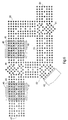
- Fig. 4 shows an embodiment in which the photonic crystal forming needles 14 are inclined.
- a cover layer 15 is placed on selected areas, so that light exits there and 16 through attached lenses preferably polymeric material in not shown Entry window focused on a level above becomes.
- the lenses can in a known manner with electron beam lithography or be generated with optical methods.
- Fig. 5 shows a section of an inventive Circuit in which a plurality of branches 21 to 25 of a photonic crystal 26, one being Lens 27 to 31 on the light emerging from the branch Entry areas 32 to 36 focused on next to the photonic crystal 26 extending further optical Elements 37, 38 are arranged.
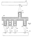
- FIG. 6 shows a Mach-Zehnder interferometer trained embodiment. All elements are especially waveguides, filters, mirrors and Beam splitter formed by photonic crystals. With the Interferometer is said to reflect the transit time in a Fig. 6 only indicated measurement object 41 can be measured.
- the light supplied at 42 is first of all adjustable filter 43 passed, with the help of Measurement to be used is selected.
- the end the filter 43 emerging light is by means of a Beam splitter 44 in equal parts straight to one adjustable phase shifter 45 and reflected to Object 41 passed.
- the adjustable filter 43 and the adjustable one Phase shifters 45 each consist of a photonic Crystal, the spaces with non-linear optical Material are filled, its dielectric constant and thus the optically effective distances between the needles With the help of electrodes 46, 47 and 48, 49, respectively Voltages are controllable.
- the phase shifter 45 is completely closed reflective mirror 50, which from the Phase shifter 45 emerging light another Beam splitter 51 supplies.
- a direction switch 42 trained photonic crystal arranged with the Effect that the light arriving from the beam splitter 44 in the object 41 is guided and that in the measurement object reflected light via a waveguide 43 for further Beam splitter 51 arrives.
- exit 54 overlap both luminous fluxes.
- a suitable transducer can measure the intensity emerging from the output 54 and by setting the phase at 45 to a minimum of Intensity at output 54 is the phase shift in the test object 41 can be determined.
- the circuit shown in FIG. 6 can also be extremely small be interpreted, for example with an entire length of about 20 ⁇ m.
Landscapes
- Physics & Mathematics (AREA)
- Optics & Photonics (AREA)
- Engineering & Computer Science (AREA)
- Chemical & Material Sciences (AREA)
- General Physics & Mathematics (AREA)
- Nonlinear Science (AREA)
- Nanotechnology (AREA)
- Life Sciences & Earth Sciences (AREA)
- Biophysics (AREA)
- Crystallography & Structural Chemistry (AREA)
- Microelectronics & Electronic Packaging (AREA)
- Optical Integrated Circuits (AREA)
- Optical Couplings Of Light Guides (AREA)
Abstract
Description
Die Erfindung betrifft eine integrierte optische Schaltung mit einem Siliziumsubstrat und darauf angeordneten Wellenleitern mit mindestens einem photonischen Kristall.The invention relates to an integrated optical circuit with a silicon substrate and arranged thereon Waveguides with at least one photonic crystal.
Integrierte optische Schaltungen werden in der Nachrichtentechnik für verschiedene Zwecke benötigt, beispielsweise zur Verteilung, Zusammenfassung, spektralen Aufteilung oder zum Schalten von mit Informationen modulierten Lichtströmen. Außerdem können auch andere Schaltungen mit Hilfe optischer Strukturen realisiert werden, beispielsweise Rechnerschaltungen.Integrated optical circuits are used in the Communication technology needed for different purposes for example for distribution, summary, spectral Splitting or switching with information modulated luminous flux. In addition, others can Circuits implemented using optical structures are, for example computer circuits.
Zur Zeit werden integrierte optische Schaltungen mit Wellenleitern aus Polymeren oder III-V-Verbindungs-Halbleitern aufgebaut, die durch lithographische Verfahren strukturiert werden.Integrated optical circuits are currently being used Polymer waveguides or III-V compound semiconductors built by lithographic processes are structured.
Als optisch wirksame Elemente dieser Schaltungen sind unter anderem photonische Kristalle geeignet, die wegen ihrer geringen geometrischen Abmessungen zur Entfaltung ihrer vollen Wirkung ein Wellenleiter-Muster benötigen, in das sie eingefügt werden. Derartige Wellenleiter-Muster sind üblicherweise Streifen-Wellenleiter aus Polymer oder Halbleitermaterial.As optically effective elements of these circuits are under other photonic crystals suitable because of their small geometric dimensions to develop their full effect a waveguide pattern in which they need be inserted. Such waveguide patterns are usually polymer or striped waveguides Semiconductor material.
Diese Wellenleiter-Muster können in einer komplementären Struktur erzeugt werden, die die Ausbreitung der Photonen-Pulse in der Materie durch ihre Ausführungsform verhindern und die Ausbreitung durch gezielte eingebaute Defekte in sonst vollständig spiegelnde Materie ermöglicht. These waveguide patterns can be complementary Structure are generated that spread the Photon pulses in matter by their embodiment prevent and spread by targeted built-in Defects in otherwise completely reflective matter.
Dabei wirkt nicht ein Brechzahlsprung wie bei der Führung von Wellen in optischen Wellenleitern, die durch Dotierung oder als Streifen-Wellenleiter ausgebildet sind, sondern hier begrenzen - theoretisch gegeben - verbotene Bänder die Zustands-Lösung der für bestimmte Wellenlängen erwünschten Eigenlösungen zur Ausbreitung dieser Wellen. Die Beschreibung dieser Wellenleiter ist beispielsweise von Mekis A. et al in Physical Review Letters, Volume 77, No. 18, p. 3787 beschrieben.A jump in the refractive index is not the same as with leadership of waves in optical waveguides by doping or are designed as strip waveguides, but here - theoretically given - forbidden bands limit the State solution of the desired for certain wavelengths In-house solutions for the propagation of these waves. The Description of this waveguide is for example from Mekis A. et al in Physical Review Letters, Volume 77, No. 18, p. 3787.
Derartige zweidimensionale photonische Kristalle können als
Filter verwendet werden, was beispielsweise in Koops, Hans
W.P.: "Photonic Crystals Built by Three-dimensional Additive
Lithography Enable Integrated Optics of High Density",
Proceedings of the SPIE, Band 2849, 5. August 1996, Seiten
248 bis 256 beschrieben ist. Dabei werden einzelne räumlich
verteilte Elemente (Drähte) der photonischen Kristalle aus
unterschiedlichem Material hergestellt. Ferner sind
dreidimensionale photonische Kristalle durch Cheng C C et
al.: Fabrication PF Photonic Band-Gap Crystals' Journal of
Vacuum Science and Technology: Part B, Band 13, Nr. 6, 01.
November 1995, Seiten 2696 bis 2700 bekanntgeworden.Such two-dimensional photonic crystals can be used as
Filters are used, for example in Koops, Hans
W.P .: "Photonic Crystals Built by Three-dimensional Additives
Lithography Enable Integrated Optics of High Density ",
Proceedings of the SPIE, volume 2849, August 5, 1996, pages
248 to 256. Individuals become spatial
distributed elements (wires) of the photonic crystals
different material. Furthermore are
three-dimensional photonic crystals by Cheng C C et
al .: Fabrication PF Photonic Band-Gap Crystals' Journal of
Vacuum Science and Technology: Part B,
Aufgabe der vorliegenden Erfindung ist es, eine integrierte optische Schaltung anzugeben, bei der von photonischen Kristallen gebildete Wellenleiter für wellenlängenabhängige Ausspiegelungen aus der Substratebene angewendet werden und die mit der erforderlichen Präzision herstellbar ist.The object of the present invention is an integrated specify optical circuit when using photonic Crystals formed waveguides for wavelength dependent Reflections from the substrate level are applied and that can be manufactured with the required precision.
Diese Aufgabe wird erfindungsgemäße dadurch gelöst, daß von jeweils einer Nadel oder einer Bohrung gebildete Elemente, die den photonischen Kristall bilden, schräg zur optischen Achse stehen und zueinander parallel angeordnet sind. Dabei ist vorzugsweise vorgesehen, daß weitere Wellenleiter als Streifen-Wellenleiter ausgebildet sind, wobei zwischen den Streifen-Wellenleitern und dem Siliziumsubstrat eine Isolierschicht angeordnet ist, und daß sich der photonische Kristall von einer Ebene unterhalb der unteren Begrenzungsfläche der Wellenleiter über die obere Begrenzungsfläche der Wellenleiter hinaus erstreckt.This object is achieved in that elements each formed of a needle or a bore, that form the photonic crystal, obliquely to the optical Stand axis and are arranged parallel to each other. there it is preferably provided that more waveguides than Strip waveguides are formed, being between the Strip waveguides and the silicon substrate one Insulating layer is arranged, and that the photonic Crystal from a level below the bottom Boundary surface of the waveguide over the upper one Boundary surface of the waveguide extends.
Zur Herstellung der erfindungsgemäßen Schaltung kann mit Vorteil das kommerziell erhältliche Material "Silizium auf Isolator" eingesetzt werden, beispielsweise von dem Hersteller SOITEC SA., Grenoble, Frankreich. Dieses Material ist für Wellenlängen von 1,55 µm gut durchlässig. Silizium besitzt bei diesen Wellenleitern eine sehr hohe Dielektrizitätskonstante von 12, das auch bei den photonischen Kristallen eingesetzt werden kann. An bestimmten Stellen der Schaltung mit sehr geringer Einfügedämpfung eingesetzte spezielle photonische Kristalle gewährleisten die Funktion der Schaltung, beispielsweise als Rechenschaltung, wobei die gesamte Schaltung sehr klein ausgeführt werden kann. So sind beispielsweise 6 Perioden des Gitters der photonischen Kristalle mit einem Gitterabstand von 1/3 der Wellenlänge ausreichend, um eine Abschwächung von 35 dB zu erreichen.To produce the circuit according to the invention, Advantage of the commercially available material "silicon Isolator "are used, for example by the Manufacturer SOITEC SA., Grenoble, France. This material is well transmissive for wavelengths of 1.55 µm. silicon has a very high one with these waveguides Dielectric constant of 12, which is also the case with the photonic crystals can be used. On certain points of the circuit with very little Insertion loss used special photonic crystals ensure the function of the circuit, for example as Arithmetic circuit, the entire circuit being very small can be executed. For example, there are 6 periods of the lattice of photonic crystals with a Grid spacing of 1/3 of the wavelength is sufficient to achieve a To achieve attenuation of 35 dB.
Eine vorteilhafte Ausgestaltung der erfindungsgemäßen Schaltung besteht darin, daß die Elemente des mindestens einen photonischen Kristalls Nadeln mit einer hohen Dielektrizitätskonstanten sind, die in Form eines zweidimensionalen periodischen Gitters angeordnet sind. Es ist jedoch auch durchaus möglich, daß die Elemente des mindestens einen photonischen Kristalls Löcher niedriger Dielektrizitätskonstanten in einem Körper mit einer hohen Dielektrizitätskonstanten sind, die in Form eines zweidimensionalen periodischen Gitters angeordnet sind.An advantageous embodiment of the invention Circuit is that the elements of at least a photonic crystal with a high needles Dielectric constants are in the form of a two-dimensional periodic grating are arranged. It However, it is also quite possible that the elements of the at least one photonic crystal holes lower Dielectric constant in a body with a high Dielectric constants are in the form of a two-dimensional periodic grating are arranged.
Je nach Voraussetzungen im einzelnen kann vorgesehen sein, daß die Nadeln auf der Isolierschicht stehen, die im Bereich des photonischen Kristalls eine geringere Stärke als unter den Wellenleitern aufweist, oder daß die Nadeln auf dem Siliziumsubstrat stehen.Depending on the requirements in detail, it can be provided that that the needles are on the insulating layer that in the area of the photonic crystal is less strong than below the waveguides, or that the needles on the Silicon substrate stand.
Eine vorteilhafte Weiterbildung der erfindungsgemäßen Schaltung besteht darin, daß die Zwischenräume zwischen den Nadeln mit nicht-linear-optischem Material ausgefüllt sind und daß mit Hilfe von einer an Feldelektroden angelegten Spannung der Brechungsindex des nicht-linear-optischen Materials einstellbar ist. Damit ist eine Steuerung, beispielsweise des Verhaltens von Filtern möglich, die als integrierte optische Schaltungen ausgeführt sind, siehe auch DE 196 34 893 A1.An advantageous development of the invention Circuit is that the gaps between the Needles are filled with non-linear optical material and that with the help of one applied to field electrodes Voltage the refractive index of the non-linear optical Material is adjustable. This is a control For example, the behavior of filters that can be viewed as Integrated optical circuits are implemented, see also DE 196 34 893 A1.
Eine weitere vorteilhafte Ausgestaltung besteht darin, daß der mindestens eine photonische Kristall durch die Anordnung der Störstellen ein Abzweigfilter darstellt, bei dem abgezweigtes Licht eines selektierten Wellenlängenbereichs seitlich austritt und der Rest des Lichtes im photonischen Kristall weitergeleitet wird. Das seitliche austretende Licht kann in vielfältiger Weise weitergeleitet werden.Another advantageous embodiment is that the at least one photonic crystal by the arrangement the impurities represent a branch filter in which branched light of a selected wavelength range emerges laterally and the rest of the light in the photonic Crystal is forwarded. The side exiting Light can be transmitted in a variety of ways.
Bei einer anderen Weiterbildung der Erfindung ist vorgesehen, daß seitlich austretendes Licht verschiedener Wellenlängenbereiche auf verschiedene Stellen eines parallel verlaufenden photonischen Kristalls fokussierbar ist. Damit ist die Möglichkeit der Verbindung mehrerer Rechenebenen in einfacher Weise gegeben.Another development of the invention is provided that laterally emerging light of various Wavelength ranges in parallel at different places extending photonic crystal is focusable. In order to is the possibility of connecting multiple computing levels in given in a simple way.
Ausführungsbeispiele der Erfindung sind in der Zeichnung anhand mehrerer Figuren dargestellt und in der nachfolgenden Beschreibung näher erläutert. Es zeigt:
- Fig. 1
- einen Querschnitt aus einem Ausschnitt aus einer erfindungsgemäßen Schaltung,
- Fig. 2
- eine Draufsicht des in Fig. 1 dargestellten Ausschnitts,
- Fig. 3
- eine Draufsicht eiens Teils eines weiteren Ausführungsbeispiels,
- Fig. 4
- ein Beispiel für eine optische Verbindung zweier Ebenen der integrierten optischen Schaltung,
- Fig. 5
- eine schematische Darstellung eines Beispiels einer optischen Verbindung mehrerer Rechenebenen bei einer erfindungsgemäßen Schaltung und
- Fig. 6
- ein mit der erfindungsgemäßen Schaltung realisiertes Mach-Zehnder-Interferometer.
- Fig. 1
- 2 shows a cross section from a section of a circuit according to the invention,
- Fig. 2
- 2 shows a plan view of the detail shown in FIG. 1,
- Fig. 3
- 2 shows a plan view of a part of a further exemplary embodiment,
- Fig. 4
- an example of an optical connection of two levels of the integrated optical circuit,
- Fig. 5
- a schematic representation of an example of an optical connection of several computing levels in a circuit according to the invention and
- Fig. 6
- a Mach-Zehnder interferometer realized with the circuit according to the invention.
Bei dem Ausführungsbeispiel nach Fig. 1 befindet sich auf
einem Siliziumsubstrat 1 eine Isolierschicht 2 aus
Silizium-Oxid, auf welcher optische Streifen-Wellenleiter 3,
4 aus Silizium aufgebracht sind. Zwischen den Wellenleitern
3, 4 befindet sich ein photonischer Kristall 5, der von
einem Gitter aus Nadeln 6 gebildet ist.In the embodiment of Fig. 1 is on
an
Die Nadeln 6 stehen bei dem Ausführungsbeispiel auf der
Isolierschicht 2, die im Bereich des photonischen Kristalls
5 eine Kavität aufweist. Dadurch und daß die Nadeln über die
obere Begrenzungsebene der Wellenleiter 3, 4 hinausragen,
wird vom photonischen Kristall auch das in Randbereichen
außerhalb des Wellenleiters geführte Feld erfaßt.The
Die Nadeln 6 können in an sich bekannter Weise durch
Korpuskularstrahl-Deposition hergestellt werden. Ein
Verfahren dazu ist beispielsweise beschrieben in
DE 195 33 148 A1.The
Wie in S.Y. Lin, G. Arjavalingam: Optics Letters, Vol. 18,
No. 19, 1666 (1990) anhand von Versuchen mit
Millimeterwellen gezeigt wurde, genügen bereits sechs
Perioden des Gitters mit einer Gitterkonstanten von einem
Drittel der Wellenlänge, um eine Dämpfung von 35 dB zu
erreichen. Innerhalb des somit gedämpften
Wellenlängenbereichs kann durch gezielte Störstellen - d.h.
Auslassen von Nadeln - Wellenlängenbereiche mit geringerer
Dämpfung geschaffen werden. Bei dem anhand der Figuren 1 und
2 dargestellten Ausführungsbeispiel wird Licht mehrerer
Wellenlängen vom Wellenleiter 3 zum Wellenleiter 4 geführt,
während an einer Abzweigung 7 Licht einer ausgewählten
Wellenlänge austritt. Dabei stehen jeweils die gewählten
Abstände in dem mittleren Bereich des photonischen Kristalls
vorhandenen Nadeln lediglich beispielhaft für eine genaue
Festlegung zur Erzielung der jeweils zu erreichenden
Filtereigenschaften.As in S.Y. Lin, G. Arjavalingam: Optics Letters, Vol. 18,
No. 19, 1666 (1990) based on experiments with
Millimeter waves have been shown, six are sufficient
Periods of the lattice with a lattice constant of one
Third of the wavelength to achieve an attenuation of 35 dB
to reach. Within the thus subdued
Wavelength range can be determined by targeted impurities - i.e.
Omitting needles - Wavelength ranges with less
Damping can be created. In the case of Figures 1 and
The embodiment shown in FIG. 2 is light
Wavelengths guided from the
Bei dem Ausführungsbeispiel nach Fig. 3 sind nicht nur für
ein Filter, sondern auch für die Zuführung und Ableitungen
photonische Kristalle vorgesehen, wobei die Zuführung 11 und
die Ableitungen 12, 13 jeweils als Allpaß dadurch
ausgebildet sind, daß im mittleren Bereich keine Nadeln
vorgesehen sind.3 are not only for
a filter, but also for feeding and draining
photonic crystals provided, the
Fig. 4 zeigt ein Ausführungsbeispiel, bei dem die den
photonischen Kristall bildenden Nadeln 14 geneigt sind. In
selektierten Bereichen ist eine Deckschicht 15 aufgelegt, so
daß Licht dort austritt und durch aufgesetzte Linsen 16 aus
vorzugsweise polymeren Material in nicht dargestellte
Eintrittsfenster einer darüberliegenden Ebene fokussiert
wird. Damit sind dreidimensionale Strukturen, beispielsweise
in einer Rechnerschaltung, möglich. Die Linsen können dabei
in bekannter Weise mit Elektronenstrahl-Lithographie oder
mit optischen Verfahren erzeugt werden.Fig. 4 shows an embodiment in which the
photonic
Fig. 5 zeigt einen Ausschnitt aus einer erfindungsgemäßen
Schaltung, bei welcher mehrere Abzweigungen 21 bis 25 von
einem photonischen Kristall 26 gebildet werden, wobei eine
Linse 27 bis 31 das aus der Abzweigung austretende Licht auf
Eintrittsflächen 32 bis 36 fokussiert, die an neben dem
photonischen Kristall 26 verlaufenden weiteren optischen
Elementen 37, 38 angeordnet sind. Fig. 5 shows a section of an inventive
Circuit in which a plurality of
Fig. 6 zeigt ein als Mach-Zehnder-Interferometer
ausgebildetes Ausführungsbeispiel. Dabei sind alle Elemente,
insbesondere Wellenleiter, Filter, Spiegel und
Strahlenteiler von photonischen Kristallen gebildet. Mit dem
Interferometer soll die Laufzeit in einem reflektierenden in
Fig. 6 lediglich angedeuteten Meßobjekt 41 gemessen werden.
Dazu wird das bei 42 zugeführte Licht zunächst durch ein
einstellbares Filter 43 geleitet, mit dessen Hilfe die zur
Messung zu verwendende Wellenlänge selektiert wird. Das aus
dem Filter 43 austretende Licht wird mit Hilfe eines
Strahlenteilers 44 zu gleichen Teilen geradeaus zu einem
einstellbaren Phasenschieber 45 und reflektiertes zum
Meßobjekt 41 geleitet.6 shows a Mach-Zehnder interferometer
trained embodiment. All elements are
especially waveguides, filters, mirrors and
Beam splitter formed by photonic crystals. With the
Interferometer is said to reflect the transit time in a
Fig. 6 only indicated
Das einstellbare Filter 43 und der einstellbare
Phasenschieber 45 bestehen jeweils aus einem photonischen
Kristall, wobei die Zwischenräume mit nicht-linear-optischem
Material ausgefüllt sind, dessen Dielektrizitätskonstante
und damit die optisch wirksamen Abstände der Nadeln mit
Hilfe von an Elektroden 46, 47 bzw. 48, 49 angelegten
Spannungen steuerbar sind.The
An den Phasenschieber 45 schließt sich ein vollständig
reflektierender Spiegel 50 an, der das aus dem
Phasenschieber 45 austretende Licht einem weiteren
Strahlenteiler 51 zuführt.The
Vor dem Meßobjekt 41 ist ein als Richtungsweiche 42
ausgebildeter photonischer Kristall angeordnet mit der
Wirkung, daß das vom Strahlenteiler 44 ankommende Licht in
das Objekt 41 geleitet wird und das im Meßobjekt
reflektierte Licht über einen Wellenleiter 43 zum weiteren
Strahlenteiler 51 gelangt. Am Ausgang 54 überlagern sich
beide Lichtströme. Mit Hilfe eines geeigneten Meßwandlers
kann die aus dem Ausgang 54 austretende Intensität gemessen
und durch Einstellung der Phase bei 45 auf ein Minimum der
Intensität am Ausgang 54 die Phasenverschiebung im Meßobjekt
41 bestimmt werden. Aus den bereits oben genannten Gründen
kann auch die in Fig. 6 dargestellte Schaltung äußerst klein
ausgelegt werden, beispielsweise mit einer gesamten Länge
von etwa 20 µm.In front of the
Claims (9)
- Integrated optical circuit with a silicon substrate and thereon disposed waveguides with at least one photonic crystal, characterized in that elements (14) each formed by a needle or by a hole - said elements (14) forming the photonic crystal - stand obliquely to the optical axis and are disposed parallel to each other.
- Integrated optical circuit according to claim 1, characterized in that further waveguides are in the form of strip waveguides (3, 4), an insulating layer (2) being disposed between the strip waveguides (3, 4) and the silicon substrate (1), and in that the photonic crystal extends from a plane below the lower periphery of the waveguides (3, 4) beyond the upper periphery of the waveguides (3, 4).
- Integrated optical circuit according to any one of claim 1 or 2, characterized in that the elements of the at least one photonic crystal are needles (14) with a high dielectric constant, said needles (14) being disposed in the form of a two-dimensional periodic lattice.
- Integrated optical circuit according to any one of claim 1 or 2, characterized in that the elements of the at least one photonic crystal are holes of low dielectric constant in a body with a high dielectric constant, said holes being disposed in the form of a two-dimensional periodic lattice.
- Integrated optical circuit according to claim 3, characterized in that the needles (14) stand on the insulating layer (2), said insulating layer (2) being less thick in the region of the photonic crystal than under the waveguides (3, 4).
- Integrated optical circuit according to claim 3, characterized in that the needles stand on the silicon substrate.
- Integrated optical circuit according to any one of claim 3, 5 or 6, characterized in that the spaces between the needles are filled with nonlinearly optical material, and in that the refractive index of the nonlinearly optical material is adjustable by means of a voltage applied at field electrodes (46 to 49).
- Integrated optical circuit according to any one of the preceding claims, characterized in that the at least one photonic crystal (26), through the arrangement of the imperfections, represents a branch filter from which branched light of a selected wavelength range exits laterally.
- Integrated optical circuit according to any one of the preceding claims, characterized in that laterally exiting light of different wavelength ranges is focusable on different sites of a parallel-extending photonic crystal.
Applications Claiming Priority (3)
| Application Number | Priority Date | Filing Date | Title |
|---|---|---|---|
| DE19720784 | 1997-05-17 | ||
| DE19720784A DE19720784A1 (en) | 1997-05-17 | 1997-05-17 | Integrated optical circuit |
| PCT/EP1998/002532 WO1998053350A1 (en) | 1997-05-17 | 1998-04-29 | Integrated optical circuit |
Publications (2)
| Publication Number | Publication Date |
|---|---|
| EP0985159A1 EP0985159A1 (en) | 2000-03-15 |
| EP0985159B1 true EP0985159B1 (en) | 2001-10-24 |
Family
ID=7829800
Family Applications (1)
| Application Number | Title | Priority Date | Filing Date |
|---|---|---|---|
| EP98922783A Expired - Lifetime EP0985159B1 (en) | 1997-05-17 | 1998-04-29 | Integrated optical circuit |
Country Status (9)
| Country | Link |
|---|---|
| US (1) | US6310991B1 (en) |
| EP (1) | EP0985159B1 (en) |
| JP (1) | JP4146520B2 (en) |
| AT (1) | ATE207622T1 (en) |
| AU (1) | AU740986B2 (en) |
| CA (1) | CA2289201C (en) |
| DE (2) | DE19720784A1 (en) |
| NZ (1) | NZ337209A (en) |
| WO (1) | WO1998053350A1 (en) |
Families Citing this family (44)
| Publication number | Priority date | Publication date | Assignee | Title |
|---|---|---|---|---|
| US6788863B2 (en) | 1997-05-16 | 2004-09-07 | Mesophotonics Limited | Optical delay device |
| US6735368B2 (en) * | 1997-05-16 | 2004-05-11 | Mesophotonics Limited | Optical delay device |
| GB9710062D0 (en) * | 1997-05-16 | 1997-07-09 | British Tech Group | Optical devices and methods of fabrication thereof |
| JP2001141946A (en) * | 1999-11-16 | 2001-05-25 | Oki Electric Ind Co Ltd | Multiplexing and demultiplexing element |
| JP2001281714A (en) * | 2000-01-24 | 2001-10-10 | Minolta Co Ltd | Optical functional device and optical integrated device |
| WO2002010843A2 (en) * | 2000-07-31 | 2002-02-07 | Matsura Naomi | Configurable phontonic device |
| US6674949B2 (en) * | 2000-08-15 | 2004-01-06 | Corning Incorporated | Active photonic crystal waveguide device and method |
| US6684008B2 (en) | 2000-09-01 | 2004-01-27 | The University Of British Columbia | Planar photonic bandgap structures for controlling radiation loss |
| CA2423736A1 (en) * | 2000-09-25 | 2002-03-28 | Marconi Optical Components Limited | Mechanical deformation based on optical illumination |
| JP3586635B2 (en) * | 2000-10-19 | 2004-11-10 | 株式会社日立製作所 | Optical devices and substrates |
| DE60127729T2 (en) * | 2000-12-27 | 2007-12-27 | Nippon Telegraph And Telephone Corp. | Photonic crystal waveguide |
| US6778722B1 (en) | 2001-04-25 | 2004-08-17 | Raytheon Company | Method and apparatus for switching optical signals with a photon band gap device |
| US6936854B2 (en) | 2001-05-10 | 2005-08-30 | Canon Kabushiki Kaisha | Optoelectronic substrate |
| WO2002093248A1 (en) * | 2001-05-15 | 2002-11-21 | Massachussets Institute Of Technology | Mach-zehnder interferometer using photonic band gap crystals |
| EP1402564B1 (en) * | 2001-05-17 | 2017-07-12 | Cisco Technology, Inc. | Integrated optical/electronic circuits and associated methods of simultaneous generation thereof |
| US6775430B2 (en) * | 2001-09-04 | 2004-08-10 | Agilent Technologies, Inc. | Photonic crystal interferometric switch |
| US6782169B2 (en) * | 2001-09-05 | 2004-08-24 | University Of Delaware | System for efficient coupling to photonic crystal waveguides |
| EP1436652A2 (en) * | 2001-10-19 | 2004-07-14 | NKT Research & Innovation A/S | Integrated photonic crystal structure and method of producing same |
| FR2832224B1 (en) * | 2001-11-15 | 2004-01-16 | Commissariat Energie Atomique | MONOLITHIC MULTILAYER ELECTRONIC DEVICE AND METHOD OF MAKING SAME |
| US6760514B2 (en) * | 2002-02-27 | 2004-07-06 | Agilent Technologies, Inc. | Continuously tunable photonic crystal drop filter |
| EP1341032A1 (en) * | 2002-02-28 | 2003-09-03 | Alcatel | Optical modulator made of photonic crystal |
| GB0208255D0 (en) * | 2002-04-10 | 2002-05-22 | Imec Inter Uni Micro Electr | Photonic crystal based fiber-to-waveguide coupler for polarisation independent photonic integrated circuits |
| US6947649B2 (en) * | 2002-05-31 | 2005-09-20 | Matsushita Electric Industrial Co., Ltd. | Method of adjusting the index of refraction of photonic crystals with laser micromachining to tune transmissions within the bandgap and structure |
| US6940637B2 (en) | 2002-09-09 | 2005-09-06 | Battelle Memorial Institute | Multi-barrier photonic heterostructures |
| WO2004023180A1 (en) * | 2002-09-09 | 2004-03-18 | Battelle Memorial Institute | Wavelength separation devices incorporating multi-barrier photonic heterostructures |
| US6934441B2 (en) | 2003-09-09 | 2005-08-23 | Battelle Memorial Institute | Wavelength separation devices incorporating multi-barrier photonic heterostructures |
| GB2393264A (en) * | 2002-09-19 | 2004-03-24 | Univ Bristol | Optical photonic crystal waveguide filter |
| US6873777B2 (en) * | 2003-03-10 | 2005-03-29 | Japan Aviation Electronics Industry Limited | Two-dimensional photonic crystal device |
| US6990280B2 (en) | 2003-08-23 | 2006-01-24 | Hewlett-Packard Development Company, L.P. | Optical path with electrically conductive cladding |
| US20050041946A1 (en) * | 2003-08-23 | 2005-02-24 | Deblanc James J. | Planar layer with optical path |
| US7356215B2 (en) * | 2003-08-23 | 2008-04-08 | Hewlett-Packard Development Company, L.P. | Methods and apparatus for selectively coupling optical paths |
| DE10341030A1 (en) * | 2003-09-03 | 2005-04-07 | Christian-Albrechts-Universität Zu Kiel | III-V semiconductor for semiconductor devices comprises a waveguide consisting of a structure with a porous core with a region of crystallographic pores likewise having a porous sleeve produced by a region of current line pores |
| US7343059B2 (en) * | 2003-10-11 | 2008-03-11 | Hewlett-Packard Development Company, L.P. | Photonic interconnect system |
| FR2861854B1 (en) * | 2003-10-30 | 2006-01-13 | Centre Nat Rech Scient | FREQUENCY SELECTIVE LIGHT COUPLING-DECOUPLING DEVICE |
| JP3881666B2 (en) * | 2004-03-25 | 2007-02-14 | 国立大学法人京都大学 | Photonic crystal having heterostructure and optical device using the same |
| JP4909528B2 (en) * | 2005-04-18 | 2012-04-04 | 株式会社リコー | Light control element |
| US7545999B2 (en) * | 2005-11-01 | 2009-06-09 | Hewlett-Packard Development Company, L.P. | Photonic configuration |
| JPWO2010073708A1 (en) * | 2008-12-26 | 2012-06-14 | 日本電気株式会社 | Wavelength filter |
| US9874688B2 (en) | 2012-04-26 | 2018-01-23 | Acacia Communications, Inc. | Co-packaging photonic integrated circuits and application specific integrated circuits |
| US9435959B2 (en) | 2012-04-26 | 2016-09-06 | Acacia Communications, Inc. | Coupling of fiber optics to planar grating couplers |
| US9888283B2 (en) | 2013-03-13 | 2018-02-06 | Nagrastar Llc | Systems and methods for performing transport I/O |
| USD758372S1 (en) | 2013-03-13 | 2016-06-07 | Nagrastar Llc | Smart card interface |
| US11360278B2 (en) | 2014-10-29 | 2022-06-14 | Acacia Communications, Inc. | Optoelectronic ball grid array package with fiber |
| USD864968S1 (en) | 2015-04-30 | 2019-10-29 | Echostar Technologies L.L.C. | Smart card interface |
Family Cites Families (10)
| Publication number | Priority date | Publication date | Assignee | Title |
|---|---|---|---|---|
| DE3642897A1 (en) * | 1986-12-16 | 1988-06-30 | K O Prof Dr Thielheim | Double refracting optical material and method for its manufacture |
| US5406573A (en) * | 1992-12-22 | 1995-04-11 | Iowa State University Research Foundation | Periodic dielectric structure for production of photonic band gap and method for fabricating the same |
| US5600483A (en) * | 1994-05-10 | 1997-02-04 | Massachusetts Institute Of Technology | Three-dimensional periodic dielectric structures having photonic bandgaps |
| US5784400A (en) * | 1995-02-28 | 1998-07-21 | Massachusetts Institute Of Technology | Resonant cavities employing two dimensionally periodic dielectric materials |
| DE19526734A1 (en) * | 1995-07-21 | 1997-01-23 | Siemens Ag | Optical structure and process for its manufacture |
| US6093246A (en) * | 1995-09-08 | 2000-07-25 | Sandia Corporation | Photonic crystal devices formed by a charged-particle beam |
| DE19634893A1 (en) * | 1995-11-10 | 1997-05-15 | Deutsche Telekom Ag | Mechanical stabilisation and tuning method for photon crystal filter used in optical fibre communications |
| DE19643489C1 (en) * | 1996-10-22 | 1998-05-07 | Fraunhofer Ges Forschung | Bragg modulator |
| US6175671B1 (en) * | 1998-10-01 | 2001-01-16 | Nortel Networks Limited | Photonic crystal waveguide arrays |
| US6134369A (en) * | 1999-03-31 | 2000-10-17 | Matsushita Electric Industrial Co. | Compact optical waveguide |
-
1997
- 1997-05-17 DE DE19720784A patent/DE19720784A1/en not_active Withdrawn
-
1998
- 1998-04-29 WO PCT/EP1998/002532 patent/WO1998053350A1/en active IP Right Grant
- 1998-04-29 CA CA002289201A patent/CA2289201C/en not_active Expired - Fee Related
- 1998-04-29 AT AT98922783T patent/ATE207622T1/en active
- 1998-04-29 US US09/423,956 patent/US6310991B1/en not_active Expired - Fee Related
- 1998-04-29 JP JP54986098A patent/JP4146520B2/en not_active Expired - Fee Related
- 1998-04-29 DE DE59801875T patent/DE59801875D1/en not_active Expired - Lifetime
- 1998-04-29 AU AU75295/98A patent/AU740986B2/en not_active Ceased
- 1998-04-29 EP EP98922783A patent/EP0985159B1/en not_active Expired - Lifetime
- 1998-04-29 NZ NZ337209A patent/NZ337209A/en unknown
Also Published As
| Publication number | Publication date |
|---|---|
| EP0985159A1 (en) | 2000-03-15 |
| ATE207622T1 (en) | 2001-11-15 |
| CA2289201A1 (en) | 1998-11-26 |
| DE19720784A1 (en) | 1998-11-26 |
| NZ337209A (en) | 2002-02-01 |
| WO1998053350A1 (en) | 1998-11-26 |
| US6310991B1 (en) | 2001-10-30 |
| AU7529598A (en) | 1998-12-11 |
| AU740986B2 (en) | 2001-11-22 |
| JP4146520B2 (en) | 2008-09-10 |
| JP2002510400A (en) | 2002-04-02 |
| DE59801875D1 (en) | 2001-11-29 |
| CA2289201C (en) | 2006-10-03 |
Similar Documents
| Publication | Publication Date | Title |
|---|---|---|
| EP0985159B1 (en) | Integrated optical circuit | |
| DE60129286T2 (en) | Photonic crystal waveguide | |
| DE60133603T2 (en) | Planar waveguide device with flat passband and steep flanks | |
| DE69937014T2 (en) | Fiber optic branch with reflector | |
| EP0970396B1 (en) | Fiber-integrated photon crystals and systems | |
| DE3220352C2 (en) | ||
| DE2804105C2 (en) | ||
| WO1997033192A1 (en) | Optical multi-channel separating filter with electrically adjustable photon crystals | |
| EP0476384A1 (en) | Optical grating with several end-areas arranged side by side for output of optical waveguides | |
| DE60203383T2 (en) | Total reflection optical switch with moving drop | |
| WO1997022907A1 (en) | Thermo-optical switch | |
| DE69831765T2 (en) | Integrated optical component with polarization effect | |
| DE69633209T2 (en) | Integrated optical polarization splitter | |
| DE60028519T2 (en) | Integrated optical circuit with reduced surface wave propagation | |
| DE69933651T2 (en) | PREPARATION OF DIFFECTION GRIDS FOR OPTICAL SIGNAL DEVICES AND THESE OPTICAL SIGNAL DEVICES CONTAINING THEREOF | |
| DE3008106C2 (en) | ||
| DE4432410B4 (en) | Optoelectronic multi-wavelength device | |
| DE60127146T2 (en) | OPTICAL DEVICE | |
| EP0915353B1 (en) | Optical waveguide arrangement | |
| DE2619327A1 (en) | ELECTRO-OPTICAL SWITCH | |
| DE19809887A1 (en) | Optical signal transmission system | |
| DE4423187A1 (en) | Tunable optical arrangement | |
| DE69737491T2 (en) | Integrated optical device with active and passive waveguide regions | |
| EP0822424B1 (en) | Optical branching element | |
| DE10246547B4 (en) | Refractive index gratings and mode couplers with a refractive index grating |
Legal Events
| Date | Code | Title | Description |
|---|---|---|---|
| PUAI | Public reference made under article 153(3) epc to a published international application that has entered the european phase |
Free format text: ORIGINAL CODE: 0009012 |
|
| 17P | Request for examination filed |
Effective date: 19991217 |
|
| AK | Designated contracting states |
Kind code of ref document: A1 Designated state(s): AT BE CH CY DE DK ES FI FR GB GR IE IT LI LU MC NL PT SE |
|
| 17Q | First examination report despatched |
Effective date: 20000620 |
|
| GRAG | Despatch of communication of intention to grant |
Free format text: ORIGINAL CODE: EPIDOS AGRA |
|
| GRAG | Despatch of communication of intention to grant |
Free format text: ORIGINAL CODE: EPIDOS AGRA |
|
| GRAH | Despatch of communication of intention to grant a patent |
Free format text: ORIGINAL CODE: EPIDOS IGRA |
|
| GRAH | Despatch of communication of intention to grant a patent |
Free format text: ORIGINAL CODE: EPIDOS IGRA |
|
| GRAH | Despatch of communication of intention to grant a patent |
Free format text: ORIGINAL CODE: EPIDOS IGRA |
|
| GRAA | (expected) grant |
Free format text: ORIGINAL CODE: 0009210 |
|
| AK | Designated contracting states |
Kind code of ref document: B1 Designated state(s): AT BE CH CY DE DK ES FI FR GB GR IE IT LI LU MC NL PT SE |
|
| PG25 | Lapsed in a contracting state [announced via postgrant information from national office to epo] |
Ref country code: IE Free format text: LAPSE BECAUSE OF FAILURE TO SUBMIT A TRANSLATION OF THE DESCRIPTION OR TO PAY THE FEE WITHIN THE PRESCRIBED TIME-LIMIT Effective date: 20011024 Ref country code: FI Free format text: LAPSE BECAUSE OF FAILURE TO SUBMIT A TRANSLATION OF THE DESCRIPTION OR TO PAY THE FEE WITHIN THE PRESCRIBED TIME-LIMIT Effective date: 20011024 |
|
| REF | Corresponds to: |
Ref document number: 207622 Country of ref document: AT Date of ref document: 20011115 Kind code of ref document: T |
|
| REG | Reference to a national code |
Ref country code: CH Ref legal event code: EP |
|
| REG | Reference to a national code |
Ref country code: IE Ref legal event code: FG4D Free format text: GERMAN |
|
| REF | Corresponds to: |
Ref document number: 59801875 Country of ref document: DE Date of ref document: 20011129 |
|
| REG | Reference to a national code |
Ref country code: GB Ref legal event code: IF02 |
|
| PG25 | Lapsed in a contracting state [announced via postgrant information from national office to epo] |
Ref country code: PT Free format text: LAPSE BECAUSE OF FAILURE TO SUBMIT A TRANSLATION OF THE DESCRIPTION OR TO PAY THE FEE WITHIN THE PRESCRIBED TIME-LIMIT Effective date: 20020124 Ref country code: DK Free format text: LAPSE BECAUSE OF FAILURE TO SUBMIT A TRANSLATION OF THE DESCRIPTION OR TO PAY THE FEE WITHIN THE PRESCRIBED TIME-LIMIT Effective date: 20020124 |
|
| PG25 | Lapsed in a contracting state [announced via postgrant information from national office to epo] |
Ref country code: GR Free format text: LAPSE BECAUSE OF FAILURE TO SUBMIT A TRANSLATION OF THE DESCRIPTION OR TO PAY THE FEE WITHIN THE PRESCRIBED TIME-LIMIT Effective date: 20020125 |
|
| GBT | Gb: translation of ep patent filed (gb section 77(6)(a)/1977) |
Effective date: 20020123 |
|
| ET | Fr: translation filed | ||
| PG25 | Lapsed in a contracting state [announced via postgrant information from national office to epo] |
Ref country code: MC Free format text: LAPSE BECAUSE OF NON-PAYMENT OF DUE FEES Effective date: 20020429 Ref country code: LU Free format text: LAPSE BECAUSE OF NON-PAYMENT OF DUE FEES Effective date: 20020429 Ref country code: AT Free format text: LAPSE BECAUSE OF NON-PAYMENT OF DUE FEES Effective date: 20020429 |
|
| PG25 | Lapsed in a contracting state [announced via postgrant information from national office to epo] |
Ref country code: LI Free format text: LAPSE BECAUSE OF NON-PAYMENT OF DUE FEES Effective date: 20020430 Ref country code: ES Free format text: LAPSE BECAUSE OF FAILURE TO SUBMIT A TRANSLATION OF THE DESCRIPTION OR TO PAY THE FEE WITHIN THE PRESCRIBED TIME-LIMIT Effective date: 20020430 Ref country code: CY Free format text: LAPSE BECAUSE OF FAILURE TO SUBMIT A TRANSLATION OF THE DESCRIPTION OR TO PAY THE FEE WITHIN THE PRESCRIBED TIME-LIMIT Effective date: 20020430 Ref country code: CH Free format text: LAPSE BECAUSE OF NON-PAYMENT OF DUE FEES Effective date: 20020430 Ref country code: BE Free format text: LAPSE BECAUSE OF NON-PAYMENT OF DUE FEES Effective date: 20020430 |
|
| REG | Reference to a national code |
Ref country code: IE Ref legal event code: FD4D |
|
| PLBE | No opposition filed within time limit |
Free format text: ORIGINAL CODE: 0009261 |
|
| STAA | Information on the status of an ep patent application or granted ep patent |
Free format text: STATUS: NO OPPOSITION FILED WITHIN TIME LIMIT |
|
| 26N | No opposition filed | ||
| REG | Reference to a national code |
Ref country code: CH Ref legal event code: PL |
|
| PGFP | Annual fee paid to national office [announced via postgrant information from national office to epo] |
Ref country code: NL Payment date: 20120425 Year of fee payment: 15 Ref country code: DE Payment date: 20120620 Year of fee payment: 15 |
|
| PGFP | Annual fee paid to national office [announced via postgrant information from national office to epo] |
Ref country code: FR Payment date: 20120511 Year of fee payment: 15 Ref country code: GB Payment date: 20120423 Year of fee payment: 15 Ref country code: SE Payment date: 20120423 Year of fee payment: 15 |
|
| PGFP | Annual fee paid to national office [announced via postgrant information from national office to epo] |
Ref country code: IT Payment date: 20120424 Year of fee payment: 15 |
|
| REG | Reference to a national code |
Ref country code: NL Ref legal event code: V1 Effective date: 20131101 |
|
| REG | Reference to a national code |
Ref country code: SE Ref legal event code: EUG |
|
| GBPC | Gb: european patent ceased through non-payment of renewal fee |
Effective date: 20130429 |
|
| PG25 | Lapsed in a contracting state [announced via postgrant information from national office to epo] |
Ref country code: DE Free format text: LAPSE BECAUSE OF NON-PAYMENT OF DUE FEES Effective date: 20131101 Ref country code: GB Free format text: LAPSE BECAUSE OF NON-PAYMENT OF DUE FEES Effective date: 20130429 Ref country code: SE Free format text: LAPSE BECAUSE OF NON-PAYMENT OF DUE FEES Effective date: 20130430 |
|
| REG | Reference to a national code |
Ref country code: FR Ref legal event code: ST Effective date: 20131231 |
|
| REG | Reference to a national code |
Ref country code: DE Ref legal event code: R119 Ref document number: 59801875 Country of ref document: DE Effective date: 20131101 |
|
| PG25 | Lapsed in a contracting state [announced via postgrant information from national office to epo] |
Ref country code: NL Free format text: LAPSE BECAUSE OF NON-PAYMENT OF DUE FEES Effective date: 20131101 Ref country code: FR Free format text: LAPSE BECAUSE OF NON-PAYMENT OF DUE FEES Effective date: 20130430 Ref country code: IT Free format text: LAPSE BECAUSE OF NON-PAYMENT OF DUE FEES Effective date: 20130429 |