EP0983667B1 - System and method for equalizing delay in a dynamic packet switching network - Google Patents
System and method for equalizing delay in a dynamic packet switching network Download PDFInfo
- Publication number
- EP0983667B1 EP0983667B1 EP97927702A EP97927702A EP0983667B1 EP 0983667 B1 EP0983667 B1 EP 0983667B1 EP 97927702 A EP97927702 A EP 97927702A EP 97927702 A EP97927702 A EP 97927702A EP 0983667 B1 EP0983667 B1 EP 0983667B1
- Authority
- EP
- European Patent Office
- Prior art keywords
- transmission
- user access
- network
- delay
- path
- Prior art date
- Legal status (The legal status is an assumption and is not a legal conclusion. Google has not performed a legal analysis and makes no representation as to the accuracy of the status listed.)
- Expired - Lifetime
Links
Images


Classifications
-
- H—ELECTRICITY
- H04—ELECTRIC COMMUNICATION TECHNIQUE
- H04L—TRANSMISSION OF DIGITAL INFORMATION, e.g. TELEGRAPHIC COMMUNICATION
- H04L12/00—Data switching networks
- H04L12/54—Store-and-forward switching systems
- H04L12/56—Packet switching systems
- H04L12/5601—Transfer mode dependent, e.g. ATM
-
- H—ELECTRICITY
- H04—ELECTRIC COMMUNICATION TECHNIQUE
- H04L—TRANSMISSION OF DIGITAL INFORMATION, e.g. TELEGRAPHIC COMMUNICATION
- H04L45/00—Routing or path finding of packets in data switching networks
- H04L45/02—Topology update or discovery
- H04L45/10—Routing in connection-oriented networks, e.g. X.25 or ATM
-
- H—ELECTRICITY
- H04—ELECTRIC COMMUNICATION TECHNIQUE
- H04L—TRANSMISSION OF DIGITAL INFORMATION, e.g. TELEGRAPHIC COMMUNICATION
- H04L45/00—Routing or path finding of packets in data switching networks
- H04L45/22—Alternate routing
-
- H—ELECTRICITY
- H04—ELECTRIC COMMUNICATION TECHNIQUE
- H04Q—SELECTING
- H04Q11/00—Selecting arrangements for multiplex systems
- H04Q11/04—Selecting arrangements for multiplex systems for time-division multiplexing
- H04Q11/0428—Integrated services digital network, i.e. systems for transmission of different types of digitised signals, e.g. speech, data, telecentral, television signals
- H04Q11/0478—Provisions for broadband connections
-
- H—ELECTRICITY
- H04—ELECTRIC COMMUNICATION TECHNIQUE
- H04L—TRANSMISSION OF DIGITAL INFORMATION, e.g. TELEGRAPHIC COMMUNICATION
- H04L12/00—Data switching networks
- H04L12/54—Store-and-forward switching systems
- H04L12/56—Packet switching systems
- H04L12/5601—Transfer mode dependent, e.g. ATM
- H04L2012/5619—Network Node Interface, e.g. tandem connections, transit switching
- H04L2012/562—Routing
-
- H—ELECTRICITY
- H04—ELECTRIC COMMUNICATION TECHNIQUE
- H04L—TRANSMISSION OF DIGITAL INFORMATION, e.g. TELEGRAPHIC COMMUNICATION
- H04L12/00—Data switching networks
- H04L12/54—Store-and-forward switching systems
- H04L12/56—Packet switching systems
- H04L12/5601—Transfer mode dependent, e.g. ATM
- H04L2012/5638—Services, e.g. multimedia, GOS, QOS
- H04L2012/5646—Cell characteristics, e.g. loss, delay, jitter, sequence integrity
- H04L2012/5649—Cell delay or jitter
-
- H—ELECTRICITY
- H04—ELECTRIC COMMUNICATION TECHNIQUE
- H04L—TRANSMISSION OF DIGITAL INFORMATION, e.g. TELEGRAPHIC COMMUNICATION
- H04L12/00—Data switching networks
- H04L12/54—Store-and-forward switching systems
- H04L12/56—Packet switching systems
- H04L12/5601—Transfer mode dependent, e.g. ATM
- H04L2012/5678—Traffic aspects, e.g. arbitration, load balancing, smoothing, buffer management
- H04L2012/5681—Buffer or queue management
Definitions
- the present invention relates generally to routing and transferring data and, in particular, to a system and method for equalizing delay in a dynamic packet switching network that routes and transfers data in addressed packets.
- Telecommunication networks exist that interconnect large numbers of user stations using telecommunication facilities. These networks utilize transmission systems, switching systems, and station equipment to transmit voice, video, and data between two points.
- the physical circuits between two points in the network are referred to as links, and the points of junction of the links are referred to as nodes.
- the user stations in data transmission networks may be telephones, terminals, printers, facsimile units, computers, and the like.
- Packet switching networks were designed to provide a more efficient method of transferring data over networks. However, packet switching networks can also be used to transmit digitized voice.
- a network that uses packet switching as a means of transmitting data is commonly referred to as a packet switching data network (PSDN).
- PSDN packet switching data network
- a packet is a discrete unit of a data message that is routed individually over a PSDN.
- Each packet contains control information that enables the message to be reassembled in proper sequence before it reaches its final destination.
- Packet switching is efficient because packets occupy the channel or path through the network only for the brief time they are in transit, in contrast to a circuit-switched message, which requires the use of the transmission line for the duration of the message.
- the channel or path is made available for transfer of other packets.
- the transmission lines through the PSDN are supplemented with computerized switches that control traffic routing and flow.
- a standard feature of packet switching is automatic error detection and correction of transmitted packets.
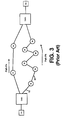
- a conventional communications network using data packet switching is shown diagrammatically in Fig. 1.
- Users and other networks access this network through user access stations ("UAS"), shown, for example, in Fig. 1 as UAS 1 , UAS 2 , and UAS 3 .
- Other networks N 1 , N 2 are considered to be like other users.
- User access stations send user data to the network and receive user data from the network through one or more switches S j .
- Paths are established through the network of switches S j in order to set up virtual communication channels between users on different user access stations. The transmissions delay for a data packet to go from one UAS to another UAS depends on the particular path chosen.
- a typical transmission delay time through the network will be referred to as T.
- T could be 20 milliseconds.
- the longest path chosen for a virtual connection through the network in a typical case has a transmission delay of 10T.
- 10T 200 milliseconds.
- Data packet size need not be constant. Data packet size can be fixed, as it is in ATM networks. However, it must be no longer than a maximum length. The maximum packet length is such that the latency time to transmit the packet over any of the links k i or l y is smaller than T/10.
- the links k i are those connecting the user access stations to the switches, and the links l y are those connecting switches to other switches.
- Some packet switching data networks are dynamic in a number of ways, for example, a network of packet switches on satellites in non-earth synchronous orbits.
- control stations CS having communication links to the network switches S j . Their function is to control the network and to set up and tear down virtual connections. Any user access station UAS can always communicate with at least one control station CS.
- the location of the control stations CS are not germane to the present invention. It will be assumed that the network interconnection pattern (links k i and ly) is predictable and can be computed by the control stations CS for any future time. In practice, all that is needed is the ability to compute the pattern into the future for the duration of the longest virtual connection established at the present time. Malfunctions can affect the predictability, but there exist ways of handling malfunctions.
- a virtual connection between two network users that lasts longer than the link lifetimes must take different paths through the network during the connection lifetime.
- a first path P 1 goes through switches S 1 , S 3 , S 4 , S 5 , S 9 , S 10 , S 11 , and S 13
- a second path P 2 goes through switches S 2 , S 6 , S 7 , S 11 , and S 13 .
- path P 1 is used during time interval t 1
- path P 2 is used during time interval t 2 , and so forth.
- a virtual connection is set up between user U 1 on UAS 1 and user U 2 on UAS 2 .
- path P A is used.
- path P B is used.
- Path P A has a transmission delay time from UAS 1 to UAS 2 equal to t a
- path P B has a transmission delay time from UAS 1 to UAS 2 equal to t b .
- the transmission delay times t a and t b are not intervals during which paths P A and P B are used, that is given by the intervals t, and t 2 .
- paths P A and P B have a common switch S c , as shown in Fig. 4a.
- the connection will be changed from path P B to path P A .
- switch S c receives packets from the connection at twice the normal rate.
- UAS 2 must maintain two links for a time interval t b - t a , during which time it gets cells at twice the normal rate for the connection. This will also result in increased delay and increased cell loss probabilities for other virtual connections.
- the apparatus of this invention comprises a system for equalizing delay in a dynamic packet switching network, comprising a buffer means for buffering a packet transmission through the network for equalizing packet transmission delay and for eliminating packet rate doubling upon changing transmission paths through the network.
- the buffer means comprises a first buffer means for buffering a packet transmission at a receiving user access station for equalizing packet delay through the network upon changing from one transmission path to another transmission path.
- the buffer means also preferably comprises a second buffer means for buffering a packet transmission at a transmitting user access station for eliminating packet rate doubling when a change is made from a longer transmission path to a shorter transmission path through the network.
- a means for controlling the second buffer means provides a first amount of buffering at the transmitting user access station immediately upon changing from a longer transmission path to a shorter transmission path through the network, and means for gradually shifting the first amount of buffering from the second buffer means to the first buffer means during a period of time following the change from a longer transmission path to a shorter transmission path.
- the apparatus hereof comprises a dynamic packet switching network, comprising first and second user access stations each having at least one buffer to delay packet transmission, and a network of switches and communication links interconnecting the first and second user access stations.
- a control station having communication links to the switches and user access stations provides means for setting up and changing transmission paths between the first and second user access stations, and means for controlling the buffers in the first and second user access stations for equalizing packet transmission delay through the network for different transmission paths.
- control station have means for controlling the buffers in the first and second user access stations for eliminating packet rate doubling when a change is made from a longer transmission path to a shorter transmission path through the network.
- the means for controlling the buffers in the first and second user access stations comprises means for causing the buffer in the second user access station to delay packets received from the first user access station for a sufficient time to cause a total transmission delay time for each transmission path equal to a transmission delay time of a longest one of the transmission paths.
- the means for controlling the buffers in the first and second user access stations comprises means for causing the buffer in the first user access station to delay packets transmitted from the first user access station to the second user access station for eliminating packet rate doubling when a change is made from a longer transmission path to a shorter transmission path.
- the means for controlling the buffers also preferably comprises means for gradually shifting the buffering provided by the buffer in the first user access station to the buffer in the second user access station during a period of time following a change from the longer transmission path to the shorter transmission path.
- the method hereof comprises a method for equalizing delay in a dynamic packet network, comprising the steps of providing first and second user access stations each having at least one buffer to delay packet transmission, and a network of switches and communication links interconnecting the first and second user access stations, setting up and changing transmission paths between the first and second user access stations across the network of switches and communication links, and controlling the buffers in the first and second user access stations to equalize packet transmission delay through the network for all of the transmission paths.
- the method comprise the step of controlling the buffers in the first and second user access stations to eliminate packet rate doubling when a change is made from a longer transmission path to a shorter transmission path through the network.
- the method also includes the step of gradually shifting a buffering from the buffer in the first user access station to the buffer in the second user access station after changing from a first longer path through the network to a second shorter path through the network.
- a system and method for equalizing data packet delay through a dynamic packet switching data network will be described.
- the system according to the present invention will also eliminate data packet rate doubling at a common switch along two paths used by one connection or data packet rate doubling at the receiving UAS.
- a receive buffer RB a operates to delay packets so that delay is equalized to that of the longest paths used by the virtual connection.
- a transmit buffer TB n operates to eliminate data packet rate doubling when a change is made from one path to another shorter path.
- a control station CS having communication links to the network switches S j and the user access stations UAS functions to control the buffers and the virtual connections of the network. The communication feeds to and from the buffers TB n , and RB o are combined at cross connect elements CC o in each of the user access stations. The details of the buffers and their operation in the packet network are described below.
- the change of a virtual connection from a path P A to a longer path P B will be described first.
- the paths can have a common switch S c before the receiving user access station UAS 2 (Fig. 5a), or the paths can enter the receiving user access station UAS 2 through two links without a common switch (Fig. 5b).
- the connection starts, for example, using path P A .
- Packets traveling along path P A undergo a transmission delay time t, from UAS 1 to UAS 2 .
- the packets traveling along path P B undergo a transmission delay time t b from UAS 1 , to UAS 2 .
- packets traveling along path P A are delayed for a time t b - t a in buffer RB 2 .
- packets traveling along path P B are not delayed at RB 2 .
- the first packet for the connection traveling along path P B arrives at RB 2 after the last packet traveling along path P A leaves the buffer RB 2 .
- transmission delay time is the same from U 1 to U 2 when paths P A or P B are used.
- the change of a virtual connection from path P B to a shorter path P A will be described next.
- the transmission delay is t b
- the packets are not delayed at either TB 1 or at RB 2 .
- the present invention avoids packet rate doubling by delaying packets for transmission along path P A for a time t b - t a in buffer TB 1 .
- the first packet traveling along path P A will arrive at S c (Fig. 5a) or at UAS 2 (Fig. 5b) after the last packet traveling along path P B arrived at S c or at UAS 2 .
- a change to a new path P C longer than P A is made.
- the connection uses paths P B , P A , and P c (in that order) with transmission delays t b , t a , and t, respectively.
- Path P B is the path with longest delay of the three paths.
- the packets are buffered and delayed for a time t b - t a in the transmit buffer TB 1 , but not in the receive buffer RB 2 . If the system simply waits until the change is made from path P A to path P C , there will be a gap of time t c - t a in the packet stream, and the total delay will be (t b - t a ) + t c , which is larger than t b because t c - t a is positive.
- the buffering delays applied in order to equalize the total delay are equal to the transmission time differences along two paths. Buffering delays are therefore also bounded by a maximum time equal to 10T.
- the average number of packets transmitted for the connection in a time 12,OOOT (path P A minimum active time) is 1,200 times larger than the average number of packets transmitted in a time 10T (maximum buffering delay). So the number of packets buffered at TB 1 is 1/1,200 times the number of packets the virtual connection delivers during the time period 12,000T, which is a lower bound to the period of time any one path is used, in particular, path P A .
- Buffering can be shifted from buffer TB 1 to RB 2 by sending packets from TB 1 to RB 2 at a rate one per thousand larger than the average for the connection.
- This procedure will take time 1,000 (t c - t a ) which is smaller than 10,000T and also smaller than the time path P A is used.
- packets are delayed at RB 2 for a time sufficient to make the total delay equal to t b .
- packets are delayed by t b - t a at TB 1 and by zero at RB 2 .
- At the end of the procedure packets are delayed by zero at TB 1 and by t b - t a at RB 2 .
- the first packet traveling along path P c will arrive at the buffer RB 2 a time t c - t a later than if it had gone along P A .
- the delay at buffer RB 2 will be t b - t c for packets traveling along path P c .
- the total transmission delay including buffering is equal to t b , as mentioned above.
- Buffers TB 2 and RB 1 are used in an analogous way to equalize delay and eliminate gaps in the packet stream for the connection in the opposite direction. The requirement that a path must be used for at least a time 12,000T need not apply to the last path used by the connection.
- Fig. 6a the process steps for an initial start of the delay equalizing process are shown.
- the process starts by determining the path P max that will be used having the maximum time delay t max (e.g., P B and t b in the example above). If the duration of the data transmission is indeterminate, the system will use the upper bound for t max .
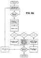
- Fig. 6b the process steps for equalizing delay in the network upon switching paths are shown.
- the buffering if any, is at RB 2 .
- the current path is P c with transmission delay t c
- the new path is P N with transmission delay t n .
- t n t c
- no buffering or delay changes are made by the control system.
- t n > t c a buffering delay of length t max - t n will be applied at RB 2 to packets traveling along path P N .
- the buffering delay was t max - t c before the change and will be t max - t a after the change.
- the control system will apply a buffering delay of length t c - t n in the buffer TB 1 .
- the system will then gradually shift the buffering from TB 1 to RB 2 using the procedure described above during the time path P N is used.
- All buffering delay will be at RB 2 and will be equal to t max - t n .
- the total transmission delay is always t max .
- the loop terminates during the use of the last path. If the process is in the middle of a buffer shifting procedure, there is no difficulty. The remaining packets in the network are delivered to U 2 with a constant delay equal to t max .
- the minimum length of time that any path (except the last) can be used can be reduced as desired. For example, if the minimum time a path must be usable is 1,200T (instead of 12,OOOT) then the buffering must be shifted from TB 1 to RB 2 , when necessary, 10 times as fast. This implies sending one more packet per one hundred packets during the buffering shift process. This requires 1% of available bandwidth to be reserved for this purpose. This can be carried further if more bandwidth is made available for shifting.
Landscapes
- Engineering & Computer Science (AREA)
- Computer Networks & Wireless Communication (AREA)
- Signal Processing (AREA)
- Data Exchanges In Wide-Area Networks (AREA)
Abstract
Description
- The present invention relates generally to routing and transferring data and, in particular, to a system and method for equalizing delay in a dynamic packet switching network that routes and transfers data in addressed packets.
- Telecommunication networks exist that interconnect large numbers of user stations using telecommunication facilities. These networks utilize transmission systems, switching systems, and station equipment to transmit voice, video, and data between two points. The physical circuits between two points in the network are referred to as links, and the points of junction of the links are referred to as nodes. The user stations in data transmission networks may be telephones, terminals, printers, facsimile units, computers, and the like.
- Packet switching networks were designed to provide a more efficient method of transferring data over networks. However, packet switching networks can also be used to transmit digitized voice. A network that uses packet switching as a means of transmitting data is commonly referred to as a packet switching data network (PSDN).
- A packet is a discrete unit of a data message that is routed individually over a PSDN. Each packet contains control information that enables the message to be reassembled in proper sequence before it reaches its final destination. Packet switching is efficient because packets occupy the channel or path through the network only for the brief time they are in transit, in contrast to a circuit-switched message, which requires the use of the transmission line for the duration of the message. On completion of the data transmission, the channel or path is made available for transfer of other packets. The transmission lines through the PSDN are supplemented with computerized switches that control traffic routing and flow. A standard feature of packet switching is automatic error detection and correction of transmitted packets.
- A conventional communications network using data packet switching is shown diagrammatically in Fig. 1. Users and other networks access this network through user access stations ("UAS"), shown, for example, in Fig. 1 as UAS1, UAS2, and UAS3. Other networks N1, N2 are considered to be like other users. User access stations send user data to the network and receive user data from the network through one or more switches Sj. Paths are established through the network of switches Sj in order to set up virtual communication channels between users on different user access stations. The transmissions delay for a data packet to go from one UAS to another UAS depends on the particular path chosen.
- A typical transmission delay time through the network will be referred to as T. For example, T could be 20 milliseconds. The longest path chosen for a virtual connection through the network in a typical case has a transmission delay of 10T. For example, for T = 20 milliseconds, 10T = 200 milliseconds.
- Data packet size need not be constant. Data packet size can be fixed, as it is in ATM networks. However, it must be no longer than a maximum length. The maximum packet length is such that the latency time to transmit the packet over any of the links ki or ly is smaller than T/10. The links ki are those connecting the user access stations to the switches, and the links ly are those connecting switches to other switches.
- Some packet switching data networks are dynamic in a number of ways, for example, a network of packet switches on satellites in non-earth synchronous orbits. The communication links ki between the user access stations UAS and the switches Sj are not permanent. Links ki are alive for a typical period of time of about 15,OOOT (for example, 5 minutes for T = 20 milliseconds). When old links ki are removed, new ones are established, but the new links ki are almost always established on a new switch Sj. For example, when link k2 (Fig. 1) is removed a new link between UAS1 and S2 may be established. There is always at least one link between a UAS and a network switch Sj.
- The links ly between switches Sj are not permanent; they have typical lifetimes of about 30,000T (for example, 10 minutes for T = 20 milliseconds). However, the pattern of links must satisfy certain conditions. There are always enough links to allow any UAS to communicate to any other UAS. Some of the links ki or ly may be permanent or much longer lived than stated above.
- In a typical system, there are control stations CS having communication links to the network switches Sj. Their function is to control the network and to set up and tear down virtual connections. Any user access station UAS can always communicate with at least one control station CS. The location of the control stations CS are not germane to the present invention. It will be assumed that the network interconnection pattern (links ki and ly) is predictable and can be computed by the control stations CS for any future time. In practice, all that is needed is the ability to compute the pattern into the future for the duration of the longest virtual connection established at the present time. Malfunctions can affect the predictability, but there exist ways of handling malfunctions.
- A virtual connection between two network users that lasts longer than the link lifetimes must take different paths through the network during the connection lifetime. It will be assumed that the dynamic interconnection pattern (links ki and ly) is such that a series of paths can be chosen for the duration of the virtual connection, and each path can be used for at least a time period 1,200T (for example, 4 minutes for T = 20 milliseconds). This is, of course, as in any other kind of network, assuming bandwidth availability. If there is not enough bandwidth available, the connection cannot be set up. Resources are reserved for the expected duration of the call. As shown in Fig. 2a, for each of a series of consecutive time intervals t1, t2, t3, ..., to there are corresponding paths P1, P2, P3, ... Pn, such that path Pi is used during time interval ti for the virtual connection.
- Referring to Fig. 2b, a first path P1, goes through switches S1, S3, S4, S5, S9, S10, S11 , and S13, while a second path P2 goes through switches S2, S6, S7, S11, and S13. For the same virtual connection between UAS1 and UAS2, path P1 is used during time interval t1, and path P2 is used during time interval t2, and so forth.
- Problems are caused by the changes in paths through the network used by one virtual connection. As shown in Fig. 3, a virtual connection is set up between user U1 on UAS1 and user U2 on UAS2. During the first time interval t1, path PA is used. During the second time interval t2, path PB is used. Path PA has a transmission delay time from UAS1 to UAS2 equal to ta, while path PB has a transmission delay time from UAS1 to UAS2 equal to tb. It should be noted that the transmission delay times ta and tb are not intervals during which paths PA and PB are used, that is given by the intervals t, and t2.
- It will first be assumed that ta < tb (for example, ta = 20 milliseconds and tb = 100 milliseconds), and that there is no buffering at UAS2. After the end of time interval t1, the virtual connection uses path PB instead of path PA. The first data packet traveling along path PB will arrive at UAS2 a period of time tb - t, later than it would have if it had gone on path PA. This will leave a silent gap of duration tb - ta in the data stream (for example, tb - ta = 80 milliseconds) which is too large to be acceptable for many communication services. This problem is simple to correct, however changing from a longer path PB to a shorter path PA causes more difficult problems, as explained below.
- It will now be assumed that during the first time interval t1, path PB is used, and during the second time interval t2, path PA is used (see Figs. 4a and 4b). Again, ta is the transmission delay along path PA, and tb is the transmission delay along path PB, and ta < tb. There is no buffering at UAS2 or at UAS1.
- Now assume that paths PA and PB have a common switch Sc, as shown in Fig. 4a. At the end of the time interval t1, the connection will be changed from path PB to path PA. When a data packet first arrives at switch Sc along path PA there are earlier data packets from the connection still traveling along path PB (there is also an interpacket spacing time, but this is negligible for the problem described). There will be a period of time equal to tb - ta during which switch Sc receives packets from the connection at twice the normal rate. If the link from switch Sc to UAS2 is fully (or close to fully) utilized, switch Sc must buffer cells from this connection for a period much longer than tb - ta. If left uncorrected, this will cause delay and possibly increase cell loss probabilities for other virtual connections (cell = data packet).
- If paths PA and PB do not have a common switch, as shown in Fig. 4b, UAS2 must maintain two links for a time interval tb - ta, during which time it gets cells at twice the normal rate for the connection. This will also result in increased delay and increased cell loss probabilities for other virtual connections.
- We will now consider three prior art documents:
-
US 5,457,678 describes method and circuit arrangement for the transmission of message packets according to the asynchronous transfer mode in a communication network. Transmission of the message packets according to asynchronous transfer mode ensues separately on at least two completely different transmission paths having ATM switching equipments (ASW1......, ASW2......) or ATM cross connectors (ACC1..., ACC2). An acquisition of test message packets transmitted at the transmission side and switched on the different transmission paths ensues on the basis of an interface controller unit (CCU) located at a respective subscriber of the network. Compensation is provided of the differences in running time of the message packets caused by the different transmission paths on the basis of the reception points in time. One of a plurality of identical message packets transmitted on the different transmission paths is output to a subscriber. -
US 5,400,324 describes a method to provide link grouping in a packet switch. In a packet switch, which is intended for packets of constant length, and which, between switch ports, is divided into a number of nodes (12) and transmission links (14), where the nodes carry out space selection and the transmission links offer point-to-point transmission between the nodes, link grouping is carded out. More particularly, from multiple parallel physical links coming in the switch, link groups are produced, each in the form of a logical link with a bandwidth that is the sum of the bandwidths of the physical links included in the link group, said logical link being restored to outgoing parallel physical links from the switch. One or more link protocols (G1,G2) are used according to which a label in the packet's header is made to describe a route that holds together the grouped links through the entire switch such that bits in the label describing the route over a certain transmission link are the same for packets belonging to the same link group. -
US 5,627,822 describes method and circuit arrangement for disturbance-free redirection of a message cell stream onto an alternate route. Within a cell-oriented communication network, a switching equipment (CCa) located at the start of a path pair duplicates a message cell stream supplied thereto for redirection. The message cell streams resulting therefrom are separately supplied to a switching equipment (CCb) located at the end of the path pair via an active path (AP) and via an alternate path (EP) of the path pair allocated thereto. A decentralized synchronization means (SY) or, respectively, a plurality of decentralized synchronization means (SY1, SY2 or, respectively, SY3 SY4) is or, respectively are provided therein, a synchronization of the two message cell streams ensuing therein while initially forwarding the message cell stream of the active path. After such a synchronization, only the message cell stream of the alternate path is then forwarded. - It is thus an object of the present invention to provide an improved system and method for routing and transferring data in addressed data packets which overcome the above-described problems in dynamic packet switching networks.
- It is a further object of the present invention to provide a system and method for equalizing delay in a dynamic packet rate doubling upon changing transmission paths.
- Additional objects, advantages and novel features of the invention will be set forth in the description that follows, and will become apparent to those skilled in the art upon reading this description or practicing the invention. The objects and advantages of the invention may be realized and attained by the appended
independent claims 1 and 4. - To achieve the foregoing and other objects and in accordance with the purpose of the present invention, as embodied and broadly described herein; the apparatus of this invention comprises a system for equalizing delay in a dynamic packet switching network, comprising a buffer means for buffering a packet transmission through the network for equalizing packet transmission delay and for eliminating packet rate doubling upon changing transmission paths through the network.
- It is preferred that the buffer means comprises a first buffer means for buffering a packet transmission at a receiving user access station for equalizing packet delay through the network upon changing from one transmission path to another transmission path. The buffer means also preferably comprises a second buffer means for buffering a packet transmission at a transmitting user access station for eliminating packet rate doubling when a change is made from a longer transmission path to a shorter transmission path through the network. A means for controlling the second buffer means provides a first amount of buffering at the transmitting user access station immediately upon changing from a longer transmission path to a shorter transmission path through the network, and means for gradually shifting the first amount of buffering from the second buffer means to the first buffer means during a period of time following the change from a longer transmission path to a shorter transmission path.
- In a further aspect of the present invention, in accordance with its objects and purposes, the apparatus hereof comprises a dynamic packet switching network, comprising first and second user access stations each having at least one buffer to delay packet transmission, and a network of switches and communication links interconnecting the first and second user access stations. A control station having communication links to the switches and user access stations provides means for setting up and changing transmission paths between the first and second user access stations, and means for controlling the buffers in the first and second user access stations for equalizing packet transmission delay through the network for different transmission paths.
- It is also preferred that the control station have means for controlling the buffers in the first and second user access stations for eliminating packet rate doubling when a change is made from a longer transmission path to a shorter transmission path through the network. The means for controlling the buffers in the first and second user access stations comprises means for causing the buffer in the second user access station to delay packets received from the first user access station for a sufficient time to cause a total transmission delay time for each transmission path equal to a transmission delay time of a longest one of the transmission paths.
- It is also preferred that the means for controlling the buffers in the first and second user access stations comprises means for causing the buffer in the first user access station to delay packets transmitted from the first user access station to the second user access station for eliminating packet rate doubling when a change is made from a longer transmission path to a shorter transmission path. The means for controlling the buffers also preferably comprises means for gradually shifting the buffering provided by the buffer in the first user access station to the buffer in the second user access station during a period of time following a change from the longer transmission path to the shorter transmission path.
- In a further aspect of the present invention, in accordance with its objects and purposes, the method hereof comprises a method for equalizing delay in a dynamic packet network, comprising the steps of providing first and second user access stations each having at least one buffer to delay packet transmission, and a network of switches and communication links interconnecting the first and second user access stations, setting up and changing transmission paths between the first and second user access stations across the network of switches and communication links, and controlling the buffers in the first and second user access stations to equalize packet transmission delay through the network for all of the transmission paths.
- It is also preferred that the method comprise the step of controlling the buffers in the first and second user access stations to eliminate packet rate doubling when a change is made from a longer transmission path to a shorter transmission path through the network. The method also includes the step of gradually shifting a buffering from the buffer in the first user access station to the buffer in the second user access station after changing from a first longer path through the network to a second shorter path through the network.
- The present invention will become more clearly appreciated as the disclosure of the present invention is made with reference to the accompanying drawings, wherein:
- Fig. 1 is a schematic diagram providing a general overview of a conventional dynamic packet switching data network.
- Fig. 2a illustrates an allocation of resources for a series of consecutive time intervals for a conventional dynamic packet switching data network.
- Fig. 2b is a schematic diagram depicting the paths used during two intervals (for example) in a conventional virtual connection.
- Fig. 3 is a schematic diagram showing a virtual connection that uses different paths between two users of a conventional dynamic packet switching data network.
- Fig. 4a is a schematic diagram showing two paths with a common switch used in a virtual connection between two users of a conventional dynamic packet switching data network.
- Fig. 4b is a schematic diagram showing two paths with separate links into a receiving user access station of a conventional dynamic packet switching data network.
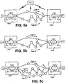
- Fig. 5a is a schematic diagram of a preferred embodiment of the present invention in which a buffer system is used at each user access station to equalize delay in the network.
- Fig. 5b is a schematic diagram of the present invention showing two paths with separate links into a receiving user access station.
- Fig. 5c is a schematic diagram of the present invention showing the delay equalizing system of the present invention used to equalize delay across three transmission paths.
- Figs. 6a and 6b are flow charts of the process steps used by the present invention to equalize delay in a dynamic packet switching data network.
- Reference will now be made in detail to a preferred embodiment of the invention, an example of which is illustrated in the accompanying drawings.
- Referring to Figs. 5a, 5b, 6a, and 6b, a system and method for equalizing data packet delay through a dynamic packet switching data network will be described. The system according to the present invention will also eliminate data packet rate doubling at a common switch along two paths used by one connection or data packet rate doubling at the receiving UAS.
- As shown in Figs. 5a and 5b, two buffers are used at each user access station UAS. A receive buffer RBa operates to delay packets so that delay is equalized to that of the longest paths used by the virtual connection. A transmit buffer TBn operates to eliminate data packet rate doubling when a change is made from one path to another shorter path. A control station CS having communication links to the network switches Sj and the user access stations UAS functions to control the buffers and the virtual connections of the network. The communication feeds to and from the buffers TBn, and RBo are combined at cross connect elements CCo in each of the user access stations. The details of the buffers and their operation in the packet network are described below.
- The change of a virtual connection from a path PA to a longer path PB will be described first. The paths can have a common switch Sc before the receiving user access station UAS2 (Fig. 5a), or the paths can enter the receiving user access station UAS2 through two links without a common switch (Fig. 5b). The connection starts, for example, using path PA. Packets traveling along path PA undergo a transmission delay time t, from UAS1 to UAS2. When the virtual connection is moved from path PA to path PB , the packets traveling along path PB undergo a transmission delay time tb from UAS1, to UAS2.
- In order to equalize the transmission delay times for paths PA and PB, packets traveling along path PA are delayed for a time tb - ta in buffer RB2. On the other hand, packets traveling along path PB are not delayed at RB2. After moving the virtual connection from path PA to path PB, the first packet for the connection traveling along path PB arrives at RB2 after the last packet traveling along path PA leaves the buffer RB2. There is no gap in the data packet stream, and transmission delay time is the same from U1 to U2 when paths PA or PB are used.
- The change of a virtual connection from path PB to a shorter path PA will be described next. During the time the connection is using path PB, the transmission delay is tb, and the packets are not delayed at either TB1 or at RB2. When the change is made to the shorter path PA, the present invention avoids packet rate doubling by delaying packets for transmission along path PA for a time tb - ta in buffer TB1. In this way, the first packet traveling along path PA will arrive at Sc (Fig. 5a) or at UAS2 (Fig. 5b) after the last packet traveling along path PB arrived at Sc or at UAS2. This eliminates data packet rate doubling and equalizes the transmission delay times for paths PA and PB.
- Referring to Fig. 5c, the present invention will next be described for the case where a change to a new path PC longer than PA is made. Assume the connection uses paths PB, PA, and Pc (in that order) with transmission delays tb, ta, and t, respectively. Also assume, as above, that ta < tb and that ta < tc, < tb. Path PB is the path with longest delay of the three paths. When the change is made from path PB to the shorter path PA the procedure described above is used. As described, the packets are buffered and delayed for a time tb - ta in the transmit buffer TB1, but not in the receive buffer RB2. If the system simply waits until the change is made from path PA to path PC, there will be a gap of time tc - ta in the packet stream, and the total delay will be (tb - ta) + tc, which is larger than tb because tc - ta is positive.
- The problem just described is avoided by shifting the buffering of packets for the virtual connection from TB1 to RB1 during the time that the path PA is being used. In one example of the present invention, it will be assumed that each path can be used for a time period of at least 12,OOOT (e.g., 4 minutes for T = 20 milliseconds), where T is the typical transmission delay through the network. It will also be assumed that there is a maximum transmission delay of 10T (e.g., 200 milliseconds for T = 20 milliseconds) for transmission across the longest path PB.
- The buffering delays applied in order to equalize the total delay are equal to the transmission time differences along two paths. Buffering delays are therefore also bounded by a maximum time equal to 10T. The average number of packets transmitted for the connection in a
time 12,OOOT (path PA minimum active time) is 1,200 times larger than the average number of packets transmitted in a time 10T (maximum buffering delay). So the number of packets buffered at TB1 is 1/1,200 times the number of packets the virtual connection delivers during the time period 12,000T, which is a lower bound to the period of time any one path is used, in particular, path PA. - Buffering can be shifted from buffer TB1 to RB2 by sending packets from TB1 to RB2 at a rate one per thousand larger than the average for the connection. This procedure will take time 1,000 (tc - ta) which is smaller than 10,000T and also smaller than the time path PA is used. During this time packets are delayed at RB2 for a time sufficient to make the total delay equal to tb. At the start of the procedure packets are delayed by tb - ta at TB1 and by zero at RB2. At the end of the procedure packets are delayed by zero at TB1 and by tb - ta at RB2.
- During the time period 1,000 (tb - ta) the delay in buffer TB1 changes linearly from tb - ta to zero, and in buffer RB2 the delay changes linearly from zero to tb - ta. At the end of this buffering shift, there is no delay at buffer TB1, and a delay of tb - ta at RB2 thus occurs near the end of the use of the path PA. When the change is made to the path Pc, the transmission delay is tc, which is longer than ta. There will now be no gap in the packet stream out of UAS2 to user U2. The first packet traveling along path Pc will arrive at the buffer RB2 a time tc - ta later than if it had gone along PA. During this time the connection to U2 is fed from the buffer RB2. The delay at buffer RB2 will be tb - tc for packets traveling along path Pc. The total transmission delay including buffering is equal to tb, as mentioned above.
- In order to accomplish the above delay equalizing procedure it is necessary to reserve 1/1,000 (0.1%) of the bandwidth in the network for buffer shifting.
- Buffers TB2 and RB1 are used in an analogous way to equalize delay and eliminate gaps in the packet stream for the connection in the opposite direction. The requirement that a path must be used for at least a time 12,000T need not apply to the last path used by the connection.
- Referring to Figs. 6a and 6b, the method for equalizing delay in a dynamic packet network according to the present invention will be further described as a series of process steps.
- In Fig. 6a, the process steps for an initial start of the delay equalizing process are shown. The process starts by determining the path Pmax that will be used having the maximum time delay tmax (e.g., PB and tb in the example above). If the duration of the data transmission is indeterminate, the system will use the upper bound for tmax. A first path Ps having a transmission delay t, is then set by the control system. If t, < tmax, the system will delay packets by tmax - t, in RB2 with no delay at TB1. If t3 = tmax, the system will not delay the packets at either TB1 or at RB2.
- In Fig. 6b, the process steps for equalizing delay in the network upon switching paths are shown. When the time comes for a path change to be made, the buffering, if any, is at RB2. The current path is Pc with transmission delay tc, and the new path is PN with transmission delay tn. If tn = tc, no buffering or delay changes are made by the control system. However, if tn > tc, a buffering delay of length tmax - tn will be applied at RB2 to packets traveling along path PN. The buffering delay was tmax - tc before the change and will be tmax - ta after the change. If tn < tc, the control system will apply a buffering delay of length tc - tn in the buffer TB1. The system will then gradually shift the buffering from TB1 to RB2 using the procedure described above during the time path PN is used. At the end of the buffer shifting procedure all buffering delay will be at RB2 and will be equal to tmax - tn. The total transmission delay is always tmax.
- The loop terminates during the use of the last path. If the process is in the middle of a buffer shifting procedure, there is no difficulty. The remaining packets in the network are delivered to U2 with a constant delay equal to tmax.
- The minimum length of time that any path (except the last) can be used can be reduced as desired. For example, if the minimum time a path must be usable is 1,200T (instead of 12,OOOT) then the buffering must be shifted from TB1 to RB2, when necessary, 10 times as fast. This implies sending one more packet per one hundred packets during the buffering shift process. This requires 1% of available bandwidth to be reserved for this purpose. This can be carried further if more bandwidth is made available for shifting.
- It will be appreciated that the present invention is not limited to the exact construction or process steps that have been described above and illustrated in the accompanying drawings, and that various modifications and changes can be made without departing from the scope thereof. It is intended that the scope of the invention only be limited by the appended claims.
Claims (6)
- A system for equalizing delay in a dynamic packet switching network in which communication links between network switches come in and out of existence for limited periods of time, said network comprising;a transmitting user access station (UAS1) and a receiving user access station (UAS2) for transmitting and receiving packets in the dynamic packet switching network ;a plurality of network switches (Sj) between said transmitting and receiving user access stations, said switches being capable of connecting at least two transmission paths (PA, PB) between said transmitting and receiving user access stations but only one transmission path between said transmitting and receiving user access stations being used for transmitting packets at one time, and said switches being operable for changing the communication links for the transmission paths through the network ;a transmit buffer (RB1) in said transmitting user access station and a receive buffer (RB2) in said receiving user access station for buffering packets andcontrol means (CS) having links to said network switches for controlling said network switches to define the transmission paths and to said user access stations for controlling said buffer means in said user ,access stations, said control means controls said receive buffer means to buffer packets being received at said receiving user access station for equalizing packet delay through the network upon changing from one transmission path to another transmission path through the network, the packets being delayed for a time period equal to the delay time associated with the transmission path having the maximum delay time,and said system being characterized in that said control means controls said transmit buffer to buffer packets being transmitted from said transmitting user access station to eliminate packet doubling upon the network changing from a longer transmission path to a shorter transmission path, the packet transmission being delayed for a time period equal to the difference in delay time between a longer path delay associated with the longer transmission path and a shorter transmission path delay associated with the shorter transmission path.
- The system according to claim 1 wherein said control means controls said transmit buffer to provide a first amount of buffering at said transmitting user access station immediately upon the changing from a longer transmission path to a shorter transmission path through the network and gradually shifts said first amount of buffering from said transmit buffer to said receive buffer during a first period,of time following the change from the longer transmission path to the shorter transmission path.
- The system according to claim 2 wherein said shorter transmission path is used for a second period of time, said first period of time being shorter than said second period of time.
- A method for equalizing delay in a dynamic packet switching network in which communication links between network switches come in and out of existence for limited periods of time, said network including a transmitting user access station (UAS1) having a transmit buffer and a receiving user access station (UAS2) having a receive buffer and a plurality of switches (Sj) configurable into at least two transmission paths interconnecting the transmit and receive user access stations, but only one transmission path interconnecting the transmitting and receiving user access stations being used for transmitting packets at a time:, said method comprising the steps of setting up and changing transmission paths between said transmitting and receiving user stations through the switches ;determining transmission delay times for transmission paths between the transmitting and receiving user access stations;controlling the receive buffer to equalize packet transmission delay through the network for all of the transmission paths, the packet transmission being delayed for a variable period of time by said receive buffer depending on the transmission delay time determined for the transmission path with the longest transmission delay time and based upon relative delay limes among changing transmission paths,and said method being characterized by further comprising the step of controlling the transmit buffer to eliminate packet rate doubling when a change is made from a longer transmission path to a shorter transmission path through the network, the packet transmission being delayed for a period of time equal to the difference in delay time between a longer transmission delay time associated with the longer transmission path and a shorter transmission delay time associated with the shorter transmission path.
- The method according to claim 4 further comprising the step of shifting buffering from the transmit buffer to the receive buffer after the first path through the network is changed to a second path through the network that is shorter than the first path.
- The method according to claim 5 further comprising the step of controlling the receive buffer to delay packets received from the transmitting user access station for a sufficient time to cause a total transmission delay for each transmission path equal to the transmission delay time of the longest one of the transmission paths.
Applications Claiming Priority (1)
| Application Number | Priority Date | Filing Date | Title |
|---|---|---|---|
| PCT/US1997/008688 WO1998053577A1 (en) | 1997-05-22 | 1997-05-22 | System and method for equalizing delay in a dynamic packet switching network |
Publications (3)
| Publication Number | Publication Date |
|---|---|
| EP0983667A1 EP0983667A1 (en) | 2000-03-08 |
| EP0983667A4 EP0983667A4 (en) | 2005-07-27 |
| EP0983667B1 true EP0983667B1 (en) | 2007-08-29 |
Family
ID=22260945
Family Applications (1)
| Application Number | Title | Priority Date | Filing Date |
|---|---|---|---|
| EP97927702A Expired - Lifetime EP0983667B1 (en) | 1997-05-22 | 1997-05-22 | System and method for equalizing delay in a dynamic packet switching network |
Country Status (5)
| Country | Link |
|---|---|
| EP (1) | EP0983667B1 (en) |
| JP (1) | JP3199386B2 (en) |
| CA (1) | CA2291192C (en) |
| DE (1) | DE69738082T2 (en) |
| WO (1) | WO1998053577A1 (en) |
Families Citing this family (5)
| Publication number | Priority date | Publication date | Assignee | Title |
|---|---|---|---|---|
| US6745049B1 (en) | 1997-12-10 | 2004-06-01 | Mitsubishi Denki Kabushiki Kaisha | Mobile communication system |
| JP2001021548A (en) | 1999-07-06 | 2001-01-26 | Kawasaki Steel Corp | Analytical method and device for free fluorine in solution containing hydrofluoric acid |
| CN100420224C (en) * | 2006-04-14 | 2008-09-17 | 杭州华三通信技术有限公司 | Network appiliance and method of realizing service sharing |
| WO2008035600A1 (en) * | 2006-09-20 | 2008-03-27 | Panasonic Corporation | Relay transmission device and relay transmission method |
| EP2950488A1 (en) * | 2014-05-27 | 2015-12-02 | Xieon Networks S.à r.l. | Adaptive traffic routing in communication networks |
Family Cites Families (10)
| Publication number | Priority date | Publication date | Assignee | Title |
|---|---|---|---|---|
| EP0215526B1 (en) * | 1985-09-19 | 1991-05-08 | BELL TELEPHONE MANUFACTURING COMPANY Naamloze Vennootschap | Data communication system |
| US5193151A (en) * | 1989-08-30 | 1993-03-09 | Digital Equipment Corporation | Delay-based congestion avoidance in computer networks |
| SE470039B (en) * | 1992-03-17 | 1993-10-25 | Ellemtel Utvecklings Ab | Ways to achieve link grouping in a packet selector |
| GB2267200B (en) * | 1992-05-19 | 1995-10-25 | Dowty Communications Ltd | Packet transmission system |
| US5381404A (en) * | 1992-07-14 | 1995-01-10 | Mita Industrial Co., Ltd. | Packet-switching communication network and method of design |
| DE4317951C1 (en) * | 1993-05-28 | 1994-05-26 | Siemens Ag | Transmitting data packets in async. transfer mode - equalising propagation delays between transmission and reception of test packets over separate paths |
| AU1572995A (en) * | 1994-02-11 | 1995-08-29 | Newbridge Networks Corporation | Method of dynamically compensating for variable transmission delays in packet networks |
| FI98772C (en) * | 1994-02-28 | 1997-08-11 | Nokia Telecommunications Oy | Procedure for route switching on a packet data connection |
| FI98773C (en) * | 1994-02-28 | 1997-08-11 | Nokia Telecommunications Oy | A method for sharing traffic in a telecommunications network implemented with ATM technology |
| DE4416718C2 (en) * | 1994-05-11 | 1997-08-21 | Siemens Ag | Circuit arrangement for the trouble-free rerouting of a message cell stream to an alternative path |
-
1997
- 1997-05-22 WO PCT/US1997/008688 patent/WO1998053577A1/en active IP Right Grant
- 1997-05-22 EP EP97927702A patent/EP0983667B1/en not_active Expired - Lifetime
- 1997-05-22 JP JP55031498A patent/JP3199386B2/en not_active Expired - Lifetime
- 1997-05-22 CA CA002291192A patent/CA2291192C/en not_active Expired - Lifetime
- 1997-05-22 DE DE69738082T patent/DE69738082T2/en not_active Expired - Lifetime
Non-Patent Citations (1)
| Title |
|---|
| None * |
Also Published As
| Publication number | Publication date |
|---|---|
| DE69738082D1 (en) | 2007-10-11 |
| EP0983667A4 (en) | 2005-07-27 |
| DE69738082T2 (en) | 2008-05-21 |
| CA2291192A1 (en) | 1998-11-26 |
| JP2000512471A (en) | 2000-09-19 |
| CA2291192C (en) | 2003-12-30 |
| EP0983667A1 (en) | 2000-03-08 |
| WO1998053577A1 (en) | 1998-11-26 |
| JP3199386B2 (en) | 2001-08-20 |
Similar Documents
| Publication | Publication Date | Title |
|---|---|---|
| US5777988A (en) | System and method for equalizing delay in a dynamic packet switching network | |
| CA2224753C (en) | An atm switch queuing system | |
| EP0780046B1 (en) | Atm communication with inverse multiplexing over multiple links | |
| US5940381A (en) | Asynchronous transfer mode radio communications system with handoff and method of operation | |
| US7126970B2 (en) | Communication system with balanced transmission bandwidth | |
| US5621722A (en) | Method and circuit arrangement for disturbance-free redirection of a message cell stream onto an alternate route | |
| US6272128B1 (en) | Method and system for emulating a T1 link over an ATM network | |
| US5386415A (en) | Packet communiction method and packet communication apparatus | |
| US5561661A (en) | Method for synchronizing redundantly transmitted message cell streams | |
| EP0820165B1 (en) | System for transmission between base station and exchange of mobile communication using fixed-length cell | |
| US5293570A (en) | Telecommunication network | |
| US7046623B2 (en) | Fault recovery system and method for inverse multiplexed digital subscriber lines | |
| EP1073239B1 (en) | Communications channel synchronous cell system for integrating circuit and packet data transmissions | |
| US6625176B1 (en) | Method and apparatus for adjustment of time delays in synchronous clocked bus systems | |
| US6683869B1 (en) | Method and system for implementing an improved DSO switching capability in a data switch | |
| EP0983667B1 (en) | System and method for equalizing delay in a dynamic packet switching network | |
| US5444699A (en) | Call and connection set up system in transmission network | |
| EP0731620B1 (en) | Handover in a mobile telecommunications network with ATM switch | |
| JP2004064619A (en) | Switching system | |
| US5715251A (en) | Local network including concentric main and relief rings | |
| US6636514B1 (en) | Telecommunications system | |
| US7397820B1 (en) | Voice packets in IP network | |
| CA2327930A1 (en) | Multi-rate atm switching system and method | |
| CA2223231A1 (en) | Fast and efficient packet transmission system and method | |
| JPS63133736A (en) | Packet instantaneous communication system |
Legal Events
| Date | Code | Title | Description |
|---|---|---|---|
| PUAI | Public reference made under article 153(3) epc to a published international application that has entered the european phase |
Free format text: ORIGINAL CODE: 0009012 |
|
| 17P | Request for examination filed |
Effective date: 19991029 |
|
| AK | Designated contracting states |
Kind code of ref document: A1 Designated state(s): DE FR GB IT SE |
|
| A4 | Supplementary search report drawn up and despatched |
Effective date: 20050610 |
|
| 17Q | First examination report despatched |
Effective date: 20050907 |
|
| GRAP | Despatch of communication of intention to grant a patent |
Free format text: ORIGINAL CODE: EPIDOSNIGR1 |
|
| GRAS | Grant fee paid |
Free format text: ORIGINAL CODE: EPIDOSNIGR3 |
|
| GRAA | (expected) grant |
Free format text: ORIGINAL CODE: 0009210 |
|
| AK | Designated contracting states |
Kind code of ref document: B1 Designated state(s): DE FR GB IT SE |
|
| REG | Reference to a national code |
Ref country code: GB Ref legal event code: FG4D |
|
| REF | Corresponds to: |
Ref document number: 69738082 Country of ref document: DE Date of ref document: 20071011 Kind code of ref document: P |
|
| RAP2 | Party data changed (patent owner data changed or rights of a patent transferred) |
Owner name: TELCORDIA TECHNOLOGIES, INC. |
|
| EN | Fr: translation not filed | ||
| PG25 | Lapsed in a contracting state [announced via postgrant information from national office to epo] |
Ref country code: SE Free format text: LAPSE BECAUSE OF FAILURE TO SUBMIT A TRANSLATION OF THE DESCRIPTION OR TO PAY THE FEE WITHIN THE PRESCRIBED TIME-LIMIT Effective date: 20071129 |
|
| PLBE | No opposition filed within time limit |
Free format text: ORIGINAL CODE: 0009261 |
|
| STAA | Information on the status of an ep patent application or granted ep patent |
Free format text: STATUS: NO OPPOSITION FILED WITHIN TIME LIMIT |
|
| 26N | No opposition filed |
Effective date: 20080530 |
|
| REG | Reference to a national code |
Ref country code: GB Ref legal event code: 732E Free format text: REGISTERED BETWEEN 20090827 AND 20090902 |
|
| PG25 | Lapsed in a contracting state [announced via postgrant information from national office to epo] |
Ref country code: IT Free format text: LAPSE BECAUSE OF NON-PAYMENT OF DUE FEES Effective date: 20080531 |
|
| PG25 | Lapsed in a contracting state [announced via postgrant information from national office to epo] |
Ref country code: FR Free format text: LAPSE BECAUSE OF FAILURE TO SUBMIT A TRANSLATION OF THE DESCRIPTION OR TO PAY THE FEE WITHIN THE PRESCRIBED TIME-LIMIT Effective date: 20080425 |
|
| PGFP | Annual fee paid to national office [announced via postgrant information from national office to epo] |
Ref country code: GB Payment date: 20160426 Year of fee payment: 20 Ref country code: DE Payment date: 20160524 Year of fee payment: 20 |
|
| REG | Reference to a national code |
Ref country code: DE Ref legal event code: R071 Ref document number: 69738082 Country of ref document: DE |
|
| REG | Reference to a national code |
Ref country code: GB Ref legal event code: PE20 Expiry date: 20170521 |
|
| PG25 | Lapsed in a contracting state [announced via postgrant information from national office to epo] |
Ref country code: GB Free format text: LAPSE BECAUSE OF EXPIRATION OF PROTECTION Effective date: 20170521 |