EP0979638B1 - Spinal implant - Google Patents
Spinal implant Download PDFInfo
- Publication number
- EP0979638B1 EP0979638B1 EP99115874A EP99115874A EP0979638B1 EP 0979638 B1 EP0979638 B1 EP 0979638B1 EP 99115874 A EP99115874 A EP 99115874A EP 99115874 A EP99115874 A EP 99115874A EP 0979638 B1 EP0979638 B1 EP 0979638B1
- Authority
- EP
- European Patent Office
- Prior art keywords
- vertebrae
- spinal implant
- implant according
- implant
- previous
- Prior art date
- Legal status (The legal status is an assumption and is not a legal conclusion. Google has not performed a legal analysis and makes no representation as to the accuracy of the status listed.)
- Expired - Lifetime
Links
Images


Classifications
-
- A—HUMAN NECESSITIES
- A61—MEDICAL OR VETERINARY SCIENCE; HYGIENE
- A61F—FILTERS IMPLANTABLE INTO BLOOD VESSELS; PROSTHESES; DEVICES PROVIDING PATENCY TO, OR PREVENTING COLLAPSING OF, TUBULAR STRUCTURES OF THE BODY, e.g. STENTS; ORTHOPAEDIC, NURSING OR CONTRACEPTIVE DEVICES; FOMENTATION; TREATMENT OR PROTECTION OF EYES OR EARS; BANDAGES, DRESSINGS OR ABSORBENT PADS; FIRST-AID KITS
- A61F2/00—Filters implantable into blood vessels; Prostheses, i.e. artificial substitutes or replacements for parts of the body; Appliances for connecting them with the body; Devices providing patency to, or preventing collapsing of, tubular structures of the body, e.g. stents
- A61F2/02—Prostheses implantable into the body
- A61F2/30—Joints
- A61F2/44—Joints for the spine, e.g. vertebrae, spinal discs
- A61F2/4455—Joints for the spine, e.g. vertebrae, spinal discs for the fusion of spinal bodies, e.g. intervertebral fusion of adjacent spinal bodies, e.g. fusion cages
- A61F2/447—Joints for the spine, e.g. vertebrae, spinal discs for the fusion of spinal bodies, e.g. intervertebral fusion of adjacent spinal bodies, e.g. fusion cages substantially parallelepipedal, e.g. having a rectangular or trapezoidal cross-section
-
- A—HUMAN NECESSITIES
- A61—MEDICAL OR VETERINARY SCIENCE; HYGIENE
- A61B—DIAGNOSIS; SURGERY; IDENTIFICATION
- A61B17/00—Surgical instruments, devices or methods, e.g. tourniquets
- A61B17/56—Surgical instruments or methods for treatment of bones or joints; Devices specially adapted therefor
- A61B17/58—Surgical instruments or methods for treatment of bones or joints; Devices specially adapted therefor for osteosynthesis, e.g. bone plates, screws, setting implements or the like
- A61B17/68—Internal fixation devices, including fasteners and spinal fixators, even if a part thereof projects from the skin
- A61B17/70—Spinal positioners or stabilisers ; Bone stabilisers comprising fluid filler in an implant
- A61B17/7059—Cortical plates
-
- A—HUMAN NECESSITIES
- A61—MEDICAL OR VETERINARY SCIENCE; HYGIENE
- A61B—DIAGNOSIS; SURGERY; IDENTIFICATION
- A61B17/00—Surgical instruments, devices or methods, e.g. tourniquets
- A61B17/56—Surgical instruments or methods for treatment of bones or joints; Devices specially adapted therefor
- A61B17/58—Surgical instruments or methods for treatment of bones or joints; Devices specially adapted therefor for osteosynthesis, e.g. bone plates, screws, setting implements or the like
- A61B17/68—Internal fixation devices, including fasteners and spinal fixators, even if a part thereof projects from the skin
- A61B17/80—Cortical plates, i.e. bone plates; Instruments for holding or positioning cortical plates, or for compressing bones attached to cortical plates
-
- A—HUMAN NECESSITIES
- A61—MEDICAL OR VETERINARY SCIENCE; HYGIENE
- A61B—DIAGNOSIS; SURGERY; IDENTIFICATION
- A61B17/00—Surgical instruments, devices or methods, e.g. tourniquets
- A61B17/56—Surgical instruments or methods for treatment of bones or joints; Devices specially adapted therefor
- A61B17/58—Surgical instruments or methods for treatment of bones or joints; Devices specially adapted therefor for osteosynthesis, e.g. bone plates, screws, setting implements or the like
- A61B17/68—Internal fixation devices, including fasteners and spinal fixators, even if a part thereof projects from the skin
- A61B17/84—Fasteners therefor or fasteners being internal fixation devices
- A61B17/86—Pins or screws or threaded wires; nuts therefor
-
- A—HUMAN NECESSITIES
- A61—MEDICAL OR VETERINARY SCIENCE; HYGIENE
- A61F—FILTERS IMPLANTABLE INTO BLOOD VESSELS; PROSTHESES; DEVICES PROVIDING PATENCY TO, OR PREVENTING COLLAPSING OF, TUBULAR STRUCTURES OF THE BODY, e.g. STENTS; ORTHOPAEDIC, NURSING OR CONTRACEPTIVE DEVICES; FOMENTATION; TREATMENT OR PROTECTION OF EYES OR EARS; BANDAGES, DRESSINGS OR ABSORBENT PADS; FIRST-AID KITS
- A61F2/00—Filters implantable into blood vessels; Prostheses, i.e. artificial substitutes or replacements for parts of the body; Appliances for connecting them with the body; Devices providing patency to, or preventing collapsing of, tubular structures of the body, e.g. stents
- A61F2/02—Prostheses implantable into the body
- A61F2/30—Joints
- A61F2/44—Joints for the spine, e.g. vertebrae, spinal discs
- A61F2/442—Intervertebral or spinal discs, e.g. resilient
-
- A—HUMAN NECESSITIES
- A61—MEDICAL OR VETERINARY SCIENCE; HYGIENE
- A61F—FILTERS IMPLANTABLE INTO BLOOD VESSELS; PROSTHESES; DEVICES PROVIDING PATENCY TO, OR PREVENTING COLLAPSING OF, TUBULAR STRUCTURES OF THE BODY, e.g. STENTS; ORTHOPAEDIC, NURSING OR CONTRACEPTIVE DEVICES; FOMENTATION; TREATMENT OR PROTECTION OF EYES OR EARS; BANDAGES, DRESSINGS OR ABSORBENT PADS; FIRST-AID KITS
- A61F2/00—Filters implantable into blood vessels; Prostheses, i.e. artificial substitutes or replacements for parts of the body; Appliances for connecting them with the body; Devices providing patency to, or preventing collapsing of, tubular structures of the body, e.g. stents
- A61F2/02—Prostheses implantable into the body
- A61F2/30—Joints
- A61F2/46—Special tools or methods for implanting or extracting artificial joints, accessories, bone grafts or substitutes, or particular adaptations therefor
- A61F2/4603—Special tools or methods for implanting or extracting artificial joints, accessories, bone grafts or substitutes, or particular adaptations therefor for insertion or extraction of endoprosthetic joints or of accessories thereof
- A61F2/4611—Special tools or methods for implanting or extracting artificial joints, accessories, bone grafts or substitutes, or particular adaptations therefor for insertion or extraction of endoprosthetic joints or of accessories thereof of spinal prostheses
-
- A—HUMAN NECESSITIES
- A61—MEDICAL OR VETERINARY SCIENCE; HYGIENE
- A61F—FILTERS IMPLANTABLE INTO BLOOD VESSELS; PROSTHESES; DEVICES PROVIDING PATENCY TO, OR PREVENTING COLLAPSING OF, TUBULAR STRUCTURES OF THE BODY, e.g. STENTS; ORTHOPAEDIC, NURSING OR CONTRACEPTIVE DEVICES; FOMENTATION; TREATMENT OR PROTECTION OF EYES OR EARS; BANDAGES, DRESSINGS OR ABSORBENT PADS; FIRST-AID KITS
- A61F2/00—Filters implantable into blood vessels; Prostheses, i.e. artificial substitutes or replacements for parts of the body; Appliances for connecting them with the body; Devices providing patency to, or preventing collapsing of, tubular structures of the body, e.g. stents
- A61F2/02—Prostheses implantable into the body
- A61F2/28—Bones
- A61F2002/2835—Bone graft implants for filling a bony defect or an endoprosthesis cavity, e.g. by synthetic material or biological material
-
- A—HUMAN NECESSITIES
- A61—MEDICAL OR VETERINARY SCIENCE; HYGIENE
- A61F—FILTERS IMPLANTABLE INTO BLOOD VESSELS; PROSTHESES; DEVICES PROVIDING PATENCY TO, OR PREVENTING COLLAPSING OF, TUBULAR STRUCTURES OF THE BODY, e.g. STENTS; ORTHOPAEDIC, NURSING OR CONTRACEPTIVE DEVICES; FOMENTATION; TREATMENT OR PROTECTION OF EYES OR EARS; BANDAGES, DRESSINGS OR ABSORBENT PADS; FIRST-AID KITS
- A61F2/00—Filters implantable into blood vessels; Prostheses, i.e. artificial substitutes or replacements for parts of the body; Appliances for connecting them with the body; Devices providing patency to, or preventing collapsing of, tubular structures of the body, e.g. stents
- A61F2/02—Prostheses implantable into the body
- A61F2/30—Joints
- A61F2002/30001—Additional features of subject-matter classified in A61F2/28, A61F2/30 and subgroups thereof
- A61F2002/30108—Shapes
- A61F2002/30199—Three-dimensional shapes
- A61F2002/30261—Three-dimensional shapes parallelepipedal
-
- A—HUMAN NECESSITIES
- A61—MEDICAL OR VETERINARY SCIENCE; HYGIENE
- A61F—FILTERS IMPLANTABLE INTO BLOOD VESSELS; PROSTHESES; DEVICES PROVIDING PATENCY TO, OR PREVENTING COLLAPSING OF, TUBULAR STRUCTURES OF THE BODY, e.g. STENTS; ORTHOPAEDIC, NURSING OR CONTRACEPTIVE DEVICES; FOMENTATION; TREATMENT OR PROTECTION OF EYES OR EARS; BANDAGES, DRESSINGS OR ABSORBENT PADS; FIRST-AID KITS
- A61F2/00—Filters implantable into blood vessels; Prostheses, i.e. artificial substitutes or replacements for parts of the body; Appliances for connecting them with the body; Devices providing patency to, or preventing collapsing of, tubular structures of the body, e.g. stents
- A61F2/02—Prostheses implantable into the body
- A61F2/30—Joints
- A61F2002/30001—Additional features of subject-matter classified in A61F2/28, A61F2/30 and subgroups thereof
- A61F2002/30316—The prosthesis having different structural features at different locations within the same prosthesis; Connections between prosthetic parts; Special structural features of bone or joint prostheses not otherwise provided for
- A61F2002/30329—Connections or couplings between prosthetic parts, e.g. between modular parts; Connecting elements
- A61F2002/30433—Connections or couplings between prosthetic parts, e.g. between modular parts; Connecting elements using additional screws, bolts, dowels, rivets or washers e.g. connecting screws
-
- A—HUMAN NECESSITIES
- A61—MEDICAL OR VETERINARY SCIENCE; HYGIENE
- A61F—FILTERS IMPLANTABLE INTO BLOOD VESSELS; PROSTHESES; DEVICES PROVIDING PATENCY TO, OR PREVENTING COLLAPSING OF, TUBULAR STRUCTURES OF THE BODY, e.g. STENTS; ORTHOPAEDIC, NURSING OR CONTRACEPTIVE DEVICES; FOMENTATION; TREATMENT OR PROTECTION OF EYES OR EARS; BANDAGES, DRESSINGS OR ABSORBENT PADS; FIRST-AID KITS
- A61F2/00—Filters implantable into blood vessels; Prostheses, i.e. artificial substitutes or replacements for parts of the body; Appliances for connecting them with the body; Devices providing patency to, or preventing collapsing of, tubular structures of the body, e.g. stents
- A61F2/02—Prostheses implantable into the body
- A61F2/30—Joints
- A61F2/30767—Special external or bone-contacting surface, e.g. coating for improving bone ingrowth
- A61F2/30771—Special external or bone-contacting surface, e.g. coating for improving bone ingrowth applied in original prostheses, e.g. holes or grooves
- A61F2002/30772—Apertures or holes, e.g. of circular cross section
- A61F2002/30774—Apertures or holes, e.g. of circular cross section internally-threaded
-
- A—HUMAN NECESSITIES
- A61—MEDICAL OR VETERINARY SCIENCE; HYGIENE
- A61F—FILTERS IMPLANTABLE INTO BLOOD VESSELS; PROSTHESES; DEVICES PROVIDING PATENCY TO, OR PREVENTING COLLAPSING OF, TUBULAR STRUCTURES OF THE BODY, e.g. STENTS; ORTHOPAEDIC, NURSING OR CONTRACEPTIVE DEVICES; FOMENTATION; TREATMENT OR PROTECTION OF EYES OR EARS; BANDAGES, DRESSINGS OR ABSORBENT PADS; FIRST-AID KITS
- A61F2/00—Filters implantable into blood vessels; Prostheses, i.e. artificial substitutes or replacements for parts of the body; Appliances for connecting them with the body; Devices providing patency to, or preventing collapsing of, tubular structures of the body, e.g. stents
- A61F2/02—Prostheses implantable into the body
- A61F2/30—Joints
- A61F2/30767—Special external or bone-contacting surface, e.g. coating for improving bone ingrowth
- A61F2/30771—Special external or bone-contacting surface, e.g. coating for improving bone ingrowth applied in original prostheses, e.g. holes or grooves
- A61F2002/30772—Apertures or holes, e.g. of circular cross section
- A61F2002/30777—Oblong apertures
-
- A—HUMAN NECESSITIES
- A61—MEDICAL OR VETERINARY SCIENCE; HYGIENE
- A61F—FILTERS IMPLANTABLE INTO BLOOD VESSELS; PROSTHESES; DEVICES PROVIDING PATENCY TO, OR PREVENTING COLLAPSING OF, TUBULAR STRUCTURES OF THE BODY, e.g. STENTS; ORTHOPAEDIC, NURSING OR CONTRACEPTIVE DEVICES; FOMENTATION; TREATMENT OR PROTECTION OF EYES OR EARS; BANDAGES, DRESSINGS OR ABSORBENT PADS; FIRST-AID KITS
- A61F2/00—Filters implantable into blood vessels; Prostheses, i.e. artificial substitutes or replacements for parts of the body; Appliances for connecting them with the body; Devices providing patency to, or preventing collapsing of, tubular structures of the body, e.g. stents
- A61F2/02—Prostheses implantable into the body
- A61F2/30—Joints
- A61F2/30767—Special external or bone-contacting surface, e.g. coating for improving bone ingrowth
- A61F2/30771—Special external or bone-contacting surface, e.g. coating for improving bone ingrowth applied in original prostheses, e.g. holes or grooves
- A61F2002/30772—Apertures or holes, e.g. of circular cross section
- A61F2002/30784—Plurality of holes
- A61F2002/30785—Plurality of holes parallel
-
- A—HUMAN NECESSITIES
- A61—MEDICAL OR VETERINARY SCIENCE; HYGIENE
- A61F—FILTERS IMPLANTABLE INTO BLOOD VESSELS; PROSTHESES; DEVICES PROVIDING PATENCY TO, OR PREVENTING COLLAPSING OF, TUBULAR STRUCTURES OF THE BODY, e.g. STENTS; ORTHOPAEDIC, NURSING OR CONTRACEPTIVE DEVICES; FOMENTATION; TREATMENT OR PROTECTION OF EYES OR EARS; BANDAGES, DRESSINGS OR ABSORBENT PADS; FIRST-AID KITS
- A61F2/00—Filters implantable into blood vessels; Prostheses, i.e. artificial substitutes or replacements for parts of the body; Appliances for connecting them with the body; Devices providing patency to, or preventing collapsing of, tubular structures of the body, e.g. stents
- A61F2/02—Prostheses implantable into the body
- A61F2/30—Joints
- A61F2/30767—Special external or bone-contacting surface, e.g. coating for improving bone ingrowth
- A61F2/30771—Special external or bone-contacting surface, e.g. coating for improving bone ingrowth applied in original prostheses, e.g. holes or grooves
- A61F2002/30772—Apertures or holes, e.g. of circular cross section
- A61F2002/30784—Plurality of holes
- A61F2002/30789—Plurality of holes perpendicular with respect to each other
-
- A—HUMAN NECESSITIES
- A61—MEDICAL OR VETERINARY SCIENCE; HYGIENE
- A61F—FILTERS IMPLANTABLE INTO BLOOD VESSELS; PROSTHESES; DEVICES PROVIDING PATENCY TO, OR PREVENTING COLLAPSING OF, TUBULAR STRUCTURES OF THE BODY, e.g. STENTS; ORTHOPAEDIC, NURSING OR CONTRACEPTIVE DEVICES; FOMENTATION; TREATMENT OR PROTECTION OF EYES OR EARS; BANDAGES, DRESSINGS OR ABSORBENT PADS; FIRST-AID KITS
- A61F2/00—Filters implantable into blood vessels; Prostheses, i.e. artificial substitutes or replacements for parts of the body; Appliances for connecting them with the body; Devices providing patency to, or preventing collapsing of, tubular structures of the body, e.g. stents
- A61F2/02—Prostheses implantable into the body
- A61F2/30—Joints
- A61F2/30767—Special external or bone-contacting surface, e.g. coating for improving bone ingrowth
- A61F2/30771—Special external or bone-contacting surface, e.g. coating for improving bone ingrowth applied in original prostheses, e.g. holes or grooves
- A61F2002/30795—Blind bores, e.g. of circular cross-section
- A61F2002/30805—Recesses of comparatively large area with respect to their low depth
-
- A—HUMAN NECESSITIES
- A61—MEDICAL OR VETERINARY SCIENCE; HYGIENE
- A61F—FILTERS IMPLANTABLE INTO BLOOD VESSELS; PROSTHESES; DEVICES PROVIDING PATENCY TO, OR PREVENTING COLLAPSING OF, TUBULAR STRUCTURES OF THE BODY, e.g. STENTS; ORTHOPAEDIC, NURSING OR CONTRACEPTIVE DEVICES; FOMENTATION; TREATMENT OR PROTECTION OF EYES OR EARS; BANDAGES, DRESSINGS OR ABSORBENT PADS; FIRST-AID KITS
- A61F2/00—Filters implantable into blood vessels; Prostheses, i.e. artificial substitutes or replacements for parts of the body; Appliances for connecting them with the body; Devices providing patency to, or preventing collapsing of, tubular structures of the body, e.g. stents
- A61F2/02—Prostheses implantable into the body
- A61F2/30—Joints
- A61F2/30767—Special external or bone-contacting surface, e.g. coating for improving bone ingrowth
- A61F2/30771—Special external or bone-contacting surface, e.g. coating for improving bone ingrowth applied in original prostheses, e.g. holes or grooves
- A61F2002/3082—Grooves
-
- A—HUMAN NECESSITIES
- A61—MEDICAL OR VETERINARY SCIENCE; HYGIENE
- A61F—FILTERS IMPLANTABLE INTO BLOOD VESSELS; PROSTHESES; DEVICES PROVIDING PATENCY TO, OR PREVENTING COLLAPSING OF, TUBULAR STRUCTURES OF THE BODY, e.g. STENTS; ORTHOPAEDIC, NURSING OR CONTRACEPTIVE DEVICES; FOMENTATION; TREATMENT OR PROTECTION OF EYES OR EARS; BANDAGES, DRESSINGS OR ABSORBENT PADS; FIRST-AID KITS
- A61F2/00—Filters implantable into blood vessels; Prostheses, i.e. artificial substitutes or replacements for parts of the body; Appliances for connecting them with the body; Devices providing patency to, or preventing collapsing of, tubular structures of the body, e.g. stents
- A61F2/02—Prostheses implantable into the body
- A61F2/30—Joints
- A61F2/30767—Special external or bone-contacting surface, e.g. coating for improving bone ingrowth
- A61F2/30771—Special external or bone-contacting surface, e.g. coating for improving bone ingrowth applied in original prostheses, e.g. holes or grooves
- A61F2002/30878—Special external or bone-contacting surface, e.g. coating for improving bone ingrowth applied in original prostheses, e.g. holes or grooves with non-sharp protrusions, for instance contacting the bone for anchoring, e.g. keels, pegs, pins, posts, shanks, stems, struts
-
- A—HUMAN NECESSITIES
- A61—MEDICAL OR VETERINARY SCIENCE; HYGIENE
- A61F—FILTERS IMPLANTABLE INTO BLOOD VESSELS; PROSTHESES; DEVICES PROVIDING PATENCY TO, OR PREVENTING COLLAPSING OF, TUBULAR STRUCTURES OF THE BODY, e.g. STENTS; ORTHOPAEDIC, NURSING OR CONTRACEPTIVE DEVICES; FOMENTATION; TREATMENT OR PROTECTION OF EYES OR EARS; BANDAGES, DRESSINGS OR ABSORBENT PADS; FIRST-AID KITS
- A61F2220/00—Fixations or connections for prostheses classified in groups A61F2/00 - A61F2/26 or A61F2/82 or A61F9/00 or A61F11/00 or subgroups thereof
- A61F2220/0025—Connections or couplings between prosthetic parts, e.g. between modular parts; Connecting elements
- A61F2220/0041—Connections or couplings between prosthetic parts, e.g. between modular parts; Connecting elements using additional screws, bolts, dowels or rivets, e.g. connecting screws
-
- A—HUMAN NECESSITIES
- A61—MEDICAL OR VETERINARY SCIENCE; HYGIENE
- A61F—FILTERS IMPLANTABLE INTO BLOOD VESSELS; PROSTHESES; DEVICES PROVIDING PATENCY TO, OR PREVENTING COLLAPSING OF, TUBULAR STRUCTURES OF THE BODY, e.g. STENTS; ORTHOPAEDIC, NURSING OR CONTRACEPTIVE DEVICES; FOMENTATION; TREATMENT OR PROTECTION OF EYES OR EARS; BANDAGES, DRESSINGS OR ABSORBENT PADS; FIRST-AID KITS
- A61F2230/00—Geometry of prostheses classified in groups A61F2/00 - A61F2/26 or A61F2/82 or A61F9/00 or A61F11/00 or subgroups thereof
- A61F2230/0063—Three-dimensional shapes
- A61F2230/0082—Three-dimensional shapes parallelepipedal
-
- A—HUMAN NECESSITIES
- A61—MEDICAL OR VETERINARY SCIENCE; HYGIENE
- A61F—FILTERS IMPLANTABLE INTO BLOOD VESSELS; PROSTHESES; DEVICES PROVIDING PATENCY TO, OR PREVENTING COLLAPSING OF, TUBULAR STRUCTURES OF THE BODY, e.g. STENTS; ORTHOPAEDIC, NURSING OR CONTRACEPTIVE DEVICES; FOMENTATION; TREATMENT OR PROTECTION OF EYES OR EARS; BANDAGES, DRESSINGS OR ABSORBENT PADS; FIRST-AID KITS
- A61F2310/00—Prostheses classified in A61F2/28 or A61F2/30 - A61F2/44 being constructed from or coated with a particular material
- A61F2310/00005—The prosthesis being constructed from a particular material
- A61F2310/00011—Metals or alloys
- A61F2310/00023—Titanium or titanium-based alloys, e.g. Ti-Ni alloys
Definitions
- the invention is based on a spinal implant the preamble of claim 1.
- Herniated discs, osteochondrosis and spondylosis Common causes of severe pain and deformans Restrictions on movement of one or more segments of the Spine resulting in a reflex Muscle tension, incorrect posture of the spine or other side effects. In case of radicular complaints with neurological failures or medullary symptoms, surgical treatment is necessary.
- the implant for stabilizing the spine, especially the cervical spine.
- the implant essentially consists of one flat body, usable between two vertebrae, the thickness of which approximates the distance between the Vertebra corresponds. Breakthroughs are made in the body to absorb bone intended.
- On the sides of the body facing the vertebrae are sawtooth-shaped Anchoring elements provided with a tip.
- DE 43 27 054 C1 describes a ventral intervertebral implant with at least one anchor bolts protruding from the contact surface of the implant on the vertebral body known.
- the anchor bolt can be extended by a gear in the implant.
- they point to the vertebrae facing ends of the anchor bolts on a tip. Breakthroughs make that possible Bone ingrowth into the implant.
- the spinal implant with the characterizing features of claim 1 the advantage that a flat body that can be used between two vertebrae is provided, the thickness of which is approximately the distance between the vertebrae equivalent. In the body there are several continuous, after open channels provided on the outside.
- the spinal implant can be used in microsurgery Spine are used. First, the defective one Intervertebral disc completely removed or the the neurological Symptomatic degenerative bone changes ablated. To stimulate bone growth, the Surface of the vertebrae roughened. Then that will Spinal implant inserted between the vertebrae and fixed over the knob-like elevations.
- the one in the Channels provided in the implant offer cancellous bone filling options.
- the bone grows into the canals and thus leads to an optimal and fast fusion between the implant and the neighboring vertebrae.
- the canals can be in one or two or in the implant three directions can be provided.
- the physiological lordosis, especially in the cervical vertebrae area Obtained spinal implant. Patients can start from be fully mobilized on the first postoperative day. The The patient's stay in the hospital is shortened remarkable compared to known treatment methods.
- the spinal implant is on the ventral side of the Spine inserted. Thanks to the help of microsurgical Methods of the spine implant according to the invention that can be used the anesthetic time is much shorter than with known treatment methods and the risk of Infections and hematomas almost eliminated. Furthermore all that is required is an operation for treatment.
- the spinal implant according to the invention is suitable especially for use in the cervical spine. However, it can also used in the other areas of the spine become.
- the spinal implant By using the spinal implant, the patient becomes not restricted in terms of mobility. It can also up to three implants between adjacent vertebrae be used.
- the hemispherical elevations are rigid with the flat one Body of the implant connected.
- the Implant in the spine becomes a recess in the vertebrae introduced, for example drilled, in which the elevations can intervene in the inserted state.
- the pressure between the vertebrae is between the implant the vertebrae are pressed in and thanks to the elevation in their position fixed.
- the growing together of the bones with the implant leads to an additional stabilization.
- the invention is as additional fastening device one with the flat body and plate connectable with at least two vertebrae intended. This is done using bone screws with the vertebrae and another flat-body screw screwed.
- the plate performs compared to that on the Implant provided engaging in the bone Surveys on additional stabilization and support The spine.
- the channels have one elongated cross section and can be made with small Bone parts of the treated patient are filled. This small parts of the bones come from the vertebrae, between the the implant is to be inserted. About bone growth to stimulate the surfaces of the vertebrae on the Roughened sides facing the implant. In addition, for the knob-like fasteners have small holes in them the vertebrae drilled. The resulting from these treatments Bone parts are collected and before the insertion of the Implants pressed into the channels. The vertebrae connect the bone in the canals, making a special one rapid fusion between the implant and the neighboring ones Whirling takes place.
- Nerve channel of the side facing away from the spine Threaded hole provided for inserting a tool. So can, for example, a threaded rod in the hole be screwed in. This enables an exact Position the implant between the two vertebrae.
- the implant is located at the intended location between the vertebrae and is the implant over the Fixing device fixed between the vertebrae, then the threaded rod can be removed again without the The implant changes its position.
- a further advantageous embodiment of the invention is the surface facing the vertebrae when inserted of the body smaller than the extent of the vertebrae in the Spine vertical plane.
- the nerve channel when inserted an indentation on the side facing the spine intended. In this way, impairment of Nerves in the nerve canal can be prevented.
- the body is made of polyethylene, especially pressed ultra high molecular low pressure polyethylene.
- This material has the advantage that it is resistant to all body fluids, is wear-resistant, shock-absorbing and body-friendly. It can also be available as a high purity raw material be placed and has a low weight.
- a Sterilization of the material is, for example, with gamma rays or ethylene oxide possible. It also affects Spinal implant made of polyethylene not the Magnetic resonance imaging or Computed Tomography. It is also easy to edit what simplifies the manufacture of the spinal implant.
- the spine implant is made of titanium. This material is also resistant to body fluids, wear-resistant and tolerated by the body.
- Fig. 1 shows a spinal implant with a flat Body 1, in which continuous channels 2 and 3 are provided.
- the channels are open to the outside and run straight in the Inside of the body. They run in two directions.
- an elevation 4 is provided, which in a Deepening of the vertebra can intervene.
- One of the sides of the Spinal implant has an indentation 5.
- FIG. 2 and 3 show the spinal implant in different views.
- Fig. 3 it can be seen that the Elevations 4 on opposite sides of the flat Body 1 are arranged.
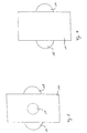
- FIG. 4 and 5 schematically show the spinal implant in the state inserted between two vertebrae 6 and 7.
- the both vertebrae 6 and 7 are shown in a highly simplified manner.
- the elevations 4 engage in the vertebrae 6 and 7. to additional stabilization and support can be a plate 8 are used with the help of bone screws 9 the vertebrae and with the help of a screw 10 on the Spine implant is attached.
- FIG. 6 to 9 is another embodiment of a Spine implant shown.
- a flat body 11 In a flat body 11 are two channels 12 and 13 with an elongated cross section, nub-like elevations 14 and 15, an indentation 16 and a threaded bore 17 is provided.
- the channels have theirs Openings on the vertebrae when inserted facing pages. You can use small pieces of bone be filled. The relatively large cross-section proves itself here of channels as an advantage.
- Threaded rod for positioning the implant between the Vertebrae are used.
Landscapes
- Health & Medical Sciences (AREA)
- Engineering & Computer Science (AREA)
- Biomedical Technology (AREA)
- Neurology (AREA)
- Orthopedic Medicine & Surgery (AREA)
- Cardiology (AREA)
- Oral & Maxillofacial Surgery (AREA)
- Transplantation (AREA)
- Heart & Thoracic Surgery (AREA)
- Vascular Medicine (AREA)
- Life Sciences & Earth Sciences (AREA)
- Animal Behavior & Ethology (AREA)
- General Health & Medical Sciences (AREA)
- Public Health (AREA)
- Veterinary Medicine (AREA)
- Prostheses (AREA)
- Surgical Instruments (AREA)
Abstract
Description
Die Erfindung geht aus von einem Wirbelsäulen-Implantat nach
dem Oberbegriff des Anspruchs 1.The invention is based on a spinal implant
the preamble of
Bandscheibenvorfälle, Osteochondrose und Spondylosis deformans sind häufig Ursachen für starke Schmerzen und Bewegungseinschränkungen eines oder mehrerer Segmente der Wirbelsäule mit der Folge einer reflektorischen Muskelverspannung, einer Fehlhaltung der Wirbelsäule oder weiteren Begleiterscheinungen. Falls radikuläre Beschwerden mit neurologischen Ausfällen oder Marksymptomatik auftreten, ist eine operative Behandlung notwendig.Herniated discs, osteochondrosis and spondylosis Common causes of severe pain and deformans Restrictions on movement of one or more segments of the Spine resulting in a reflex Muscle tension, incorrect posture of the spine or other side effects. In case of radicular complaints with neurological failures or medullary symptoms, surgical treatment is necessary.
Aus dem Stand der Technik ist bekannt, zur Behandlung dem Patienten beispielsweise aus dem Beckenkamm ein Knochenstück zu entnehmen und dieses anstelle der defekten Bandscheibe zwischen die Wirbel einzusetzen. Als nachteilig erweist sich hierbei, daß zwei Operationen mit jeweils relativ langer Operationszeit notwendig sind. Dabei können außerdem Infektionen, Hämatome oder Verletzungen von Nerven auftreten. Außerdem besteht die Gefahr einer Verletzung der im Becken verlaufenden Nerven, insbesondere des Nervus cutaneus formalis lateralis, des Nervus ilioinguinalis, des Nervus genitofemoralis und des Nervus iliohypogastricus. Im übrigen erhöht sich die Gefahr eines Bruches an der Stelle, an der das Knochenstück entnommen wurde.It is known from the prior art to treat the Patients, for example, from the iliac crest Remove the piece of bone and replace it with the broken one Insert the intervertebral disc between the vertebrae. As a disadvantage turns out to be two operations, each with relative long operation time are necessary. You can also Infections, hematomas, or injuries to nerves occur. There is also a risk of injury to the Pelvic nerves, especially the cutane nerve formalis lateralis, ilioinguinalis, the nerve genitofemoralis and iliohypogastric nerve. Furthermore the risk of breakage increases at the point where the Bone piece was removed.
Darüber hinaus ist eine Behandlung bekannt, bei der zunächst die defekte Bandscheibe entfernt und der zwischen den Wirbeln verbleibende Zwischenraum mit einer zunächst flüssigen Masse aufgefüllt wird. Die flüssige Masse erstarrt und führt zu einer Fusion mit den benachnarten Wirbeln. Als nachteilig erweist sich hierbei, daß sich die flüssige Masse zwischen den Wirbeln unkontrolliert ausbreiten kann. Dabei kann nicht verhindert werden, daß die Masse in Richtung des in den Wirbeln verlaufenden Nervenkanals fließt und im erstarrten Zustand einen Dorn bildet. Sofern dieser auf die Nerven drückt, hat der Patient auch nach der Operation Beschwerden und Schmerzen.In addition, treatment is known to begin with the defective intervertebral disc is removed and that between the vertebrae remaining space with an initially liquid mass is replenished. The liquid mass solidifies and leads to one Fusion with the neighboring vertebrae. It turns out to be disadvantageous here that the liquid mass between the vertebrae can spread uncontrollably. It cannot be prevented that the mass towards the in the vertebrae running nerve channel flows and in the solidified state forms a thorn. If it gets on your nerves, it has Patient complains and pain even after the operation.
Aus dem Stand der Technik ist außerdem als Stützmittel für die Korrektur oder die Stabilisierung der Wirbelsäule eine an mindestens zwei benachbarten Wirbeln bzw. Wirbelkörpern anbringbare längliche Platte aus verformbarem körperverträglichen Material bekannt (G 91 14 118). Diese Platte wird mit Hilfe von Knochenschrauben an den Wirbeln befestigt. Sie dient jedoch in erster Linie der Stabilisierung oder Stützung der Wirbelsäule und kann zur Behandlung beispielsweise von Bandscheibenvorfällen nicht verwendet werden.From the prior art is also used as a support for the Correction or stabilization of the spine one at least two adjacent vertebrae or vertebral bodies attachable elongated plate made of deformable body-compatible material known (G 91 14 118). This Plate is attached to the vertebrae using bone screws attached. However, it serves primarily for stabilization or Support the spine and can be used for treatment for example, of herniated discs not used become.
Aus der DE 297 03 043 U1 ist ein Wirbelsäulen-Implantat zur Stabilisierung der Wirbelsäule, insbesondere der Halswirbelsäule bekannt. Das Implantat besteht im wesentlichen aus einem flachen, zwischen zwei Wirbel einsetzbaren Körper, dessen Dicke ungefähr dem Abstand der Wirbel entspricht. Zur Aufnahme von Knochensubstanz sind in dem Körper Durchbrüche vorgesehen. An den den Wirbeln zugewandten Seiten des Körpers sind sägezahnförmige Verankerungselemente mit einer Spitze vorgesehen.DE 297 03 043 U1 describes a spinal implant for stabilizing the spine, especially the cervical spine. The implant essentially consists of one flat body, usable between two vertebrae, the thickness of which approximates the distance between the Vertebra corresponds. Breakthroughs are made in the body to absorb bone intended. On the sides of the body facing the vertebrae are sawtooth-shaped Anchoring elements provided with a tip.
Aus der DE 43 27 054 C1 ist ein ventrales Zwischenwirbelimplantat mit mindestens einem aus der Anlagefläche des Implantats an dem Wirbelkörper herausragenden Ankerbolzen bekannt. Durch ein Getriebe in dem Implantat kann der Ankerbolzen ausgefahren werden. Um beim Ausfahren in den Wirbelkörper eindringen zu können, weisen die dem Wirbelkörper zugewandten Enden der Ankerbolzen eine Spitze auf. Durchbrüche ermöglichen das Einwachsen von Knochensubstanz in das Implantat.DE 43 27 054 C1 describes a ventral intervertebral implant with at least one anchor bolts protruding from the contact surface of the implant on the vertebral body known. The anchor bolt can be extended by a gear in the implant. In order to be able to penetrate the vertebral body when extending, they point to the vertebrae facing ends of the anchor bolts on a tip. Breakthroughs make that possible Bone ingrowth into the implant.
Demgegenüber hat das Wirbelsäulen-Implantat mit den
kennzeichnenden Merkmalen des Anspruchs 1 den Vorteil, daß
ein flacher zwischen zwei Wirbeln einsetzbarer Körper
vorgesehen ist, dessen Dicke ungefähr dem Abstand der Wirbel
entspricht. In dem Körper sind mehrere durchgängige, nach
außen offene Kanäle vorgesehen. Darüber hinaus ist der flache
Körper an den den Wirbeln zugewandten Seiten mit mindestens
einer halbkugelförmigen Erhebung ausgestattet, die ein Verbinden
des Implantats mit den Wirbeln ermöglicht. Das Wirbelsäulen-Implantat
kann mit Hilfe mikrochirurgischer Technik in die
Wirbelsäule eingesetzt werden. Hierzu wird zunächst die defekte
Bandscheibe vollständig entfernt oder die die neurologische
Symptomatik verursachende degenerative Knochenveränderung
abgetragen. Um das Knochenwachstum anzuregen, wird die
Oberfläche der Wirbel aufgerauht. Anschließend wird das
Wirbelsäulen-Implantat zwischen die Wirbel eingesetzt und
über die noppenartigen Erhebungen fixiert. Die in dem
Implantat vorgesehenen Kanäle bieten Spongiosa-Füllmöglichkeiten.
Der Knochen wächst in die Kanäle hinein und
führt damit zu einer optimalen und schnellen Fusion zwischen
dem Implantat und den benachbarten Wirbeln. Die Kanäle
können in dem Implantat sowohl in einer als auch in zwei oder
drei Richtungen vorgesehen sein. Die physiologische Lordose,
insbesondere im Halswirbelbereich, wird durch das
Wirbelsäulen-Implantat erhalten. Die Patienten können ab dem
ersten postoperativen Tag voll mobilisiert werden. Der
Aufenthalt des Patienten im Krankenhaus verkürzt sich
gegenüber bekannten Behandlungsmethoden beachtlich.In contrast, the spinal implant with the
characterizing features of
Das Wirbelsäulen-Implantat wird auf der ventralen Seite der Wirbelsäule eingesetzt. Dank des mit Hilfe mikrochirurgischer Methoden einsetzbaren erfindungsgemäßen Wirbelsäulen-Implantats ist die Narkosezeit wesentlich kürzer als bei bekannten Behandlungsmethoden und die Gefahr von Infektionen und Hämatomen nahezu beseitigt. Darüber hinaus ist lediglich eine Operation zur Behandlung notwendig.The spinal implant is on the ventral side of the Spine inserted. Thanks to the help of microsurgical Methods of the spine implant according to the invention that can be used the anesthetic time is much shorter than with known treatment methods and the risk of Infections and hematomas almost eliminated. Furthermore all that is required is an operation for treatment.
Das erfindungsgemäße Wirbelsäulen-Implantat eignet sich insbesondere zum Einsatz in die Halswirbelsäule. Es kann jedoch auch in den übrigen Bereichen der Wirbelsäule eingesetzt werden. The spinal implant according to the invention is suitable especially for use in the cervical spine. However, it can also used in the other areas of the spine become.
Durch den Einsatz des Wirbelsäulen-Implantats wird der Patient hinsichtlich seiner Beweglichkeit nicht eingeschränkt. Es können auch bis zu drei Implantate zwischen benachbarten Wirbeln eingesetzt werden.By using the spinal implant, the patient becomes not restricted in terms of mobility. It can also up to three implants between adjacent vertebrae be used.
Die halbkugelförmigen Erhebungen sind starr mit dem flachen Körper des Implantats verbunden. Beim Einsetzen des Implantats in die Wirbelsäule wird in die Wirbel eine Vertiefung eingebracht, beispielsweise gebohrt, in welche die Erhebungen im eingesetzten Zustand eingreifen können. Durch den zwischen den Wirbeln herrschenden Druck wird das Implantat zwischen die Wirbel eingepreßt und dank der Erhebung in seiner Position fixiert. Das Verwachsen der Knochen mit dem Implantat führt zu einer zusätzlichen Stabilisierung.The hemispherical elevations are rigid with the flat one Body of the implant connected. When inserting the Implant in the spine becomes a recess in the vertebrae introduced, for example drilled, in which the elevations can intervene in the inserted state. By between The pressure between the vertebrae is between the implant the vertebrae are pressed in and thanks to the elevation in their position fixed. The growing together of the bones with the implant leads to an additional stabilization.
Nach einer vorteilhaften Ausgestaltung der Erfindung ist als zusätzliche Befestigungsvorrichtung eine mit dem flachen Körper und mit mindestens zwei Wirbeln verbindbare Platte vorgesehen. Diese wird über Knochenschrauben mit den Wirbeln und über eine weitere Schraube mit dem flachen Körper verschraubt. Die Platte führt im Vergleich zu den an dem Implantat vorgesehenen in den Knochen eingreifenden Erhebungen zu einer zusätzlichen Stabilisierung und Stützung der Wirbelsäule.According to an advantageous embodiment of the invention is as additional fastening device one with the flat body and plate connectable with at least two vertebrae intended. This is done using bone screws with the vertebrae and another flat-body screw screwed. The plate performs compared to that on the Implant provided engaging in the bone Surveys on additional stabilization and support The spine.
Nach einer weiteren vorteilhaften Ausgestaltung der Erfindung sind die Öffnungen der Kanäle an den den Wirbeln zugewandten Seiten des Körpers vorgesehen. Die Kanäle weisen einen länglichen Querschnitt auf und können mit kleinen Knochenteilen des behandelten Patienten befüllt werden. Diese kleinen Knochenteile stammen von den Wirbeln, zwischen die das Implantat eingesetzt werden soll. Um das Knochenwachstum anzuregen, werden die Oberflächen der Wirbel auf den dem Imlantat zugewandten Seiten aufgeraut. Außerdem werden für die noppenartigen Befestigungsvorrichtungen kleine Löcher in die Wirbel gebohrt. Die bei diesen Behandlungen anfallenden Knochenteile werden gesammelt und vor dem Einsetzen des Implants in die Kanäle gepreßt. Die Wirbel verbinden sich mit der Knochensubstanz in den Kanälen, so daß eine besonders rasche Fusion zwischen dem Implantat und den benachbarten Wirbeln stattfindet.According to a further advantageous embodiment of the invention are the openings of the channels on the vertebrae Sides of the body. The channels have one elongated cross section and can be made with small Bone parts of the treated patient are filled. This small parts of the bones come from the vertebrae, between the the implant is to be inserted. About bone growth to stimulate the surfaces of the vertebrae on the Roughened sides facing the implant. In addition, for the knob-like fasteners have small holes in them the vertebrae drilled. The resulting from these treatments Bone parts are collected and before the insertion of the Implants pressed into the channels. The vertebrae connect the bone in the canals, making a special one rapid fusion between the implant and the neighboring ones Whirling takes place.
Nach einer weiteren vorteilhaften Ausgestaltung der Erfindung ist an dem Körper an der im eingesetzten Zustand dem Nervenkanal der Wirbelsäule abgewandten Seite eine Gewindebohrung zum Einsetzen eines Werkzeugs vorgesehen. So kann beispielsweise eine Gewindestange in die Bohrung eingeschraubt werden. Diese ermöglicht ein exaktes Positionieren des Implantats zwischen den beiden Wirbeln. Befindet sich das Implantat an der vorgesehenen Stelle zwischen den Wirbeln und ist das Implantat über die Befestigungsvorrichtung zwischen den Wirbeln fixiert, dann kann die Gewindestange wieder entfernt werden, ohne daß das Implantat dabei seine Position verändert.According to a further advantageous embodiment of the invention is on the body in the used state Nerve channel of the side facing away from the spine Threaded hole provided for inserting a tool. So can, for example, a threaded rod in the hole be screwed in. This enables an exact Position the implant between the two vertebrae. The implant is located at the intended location between the vertebrae and is the implant over the Fixing device fixed between the vertebrae, then the threaded rod can be removed again without the The implant changes its position.
Nach einer weiteren vorteilhaften Ausgestaltung der Erfindung ist die den Wirbeln im eingesetzten Zustand zugewandte Fläche des Körpers kleiner als die Ausdehnung der Wirbel in der zur Wirbelsäule senkrechten Ebene. Dies führt dazu, daß das Wirbelsäulen-Implantat nicht aus der Wirbelsäule seitlich herausragt und bei entsprechendem Knochenwachstum vollständig mit Knochen umwachsen werden kann. Dabei können keine Ausbuchtungen entstehen, die die Umgebung der Wirbelsäule oder die in den Wibeln verlaufenden Nerven beeinträchtigen könnten. Die Fusion aus Wirbeln und Wirbelsäulen-Implantat zeichnet sich außerdem durch eine hohe Stabilität aus.According to a further advantageous embodiment of the invention is the surface facing the vertebrae when inserted of the body smaller than the extent of the vertebrae in the Spine vertical plane. This leads to the fact that Spinal implant not from the side of the spine protrudes and with appropriate bone growth can be completely overgrown with bones. You can no bulges arise that surround the area Spine or the nerves running in the wiggles could affect. The fusion of eddies and Spine implant is also characterized by a high Stability.
Nach einer weiteren vorteilhaften Ausgestaltung der Erfindung ist an dem Körper der im eingesetzten Zustand dem Nervenkanal der Wirbelsäule zugewandten Seite eine Einbuchtung vorgesehen. Auf diese Weise kann eine Beeinträchtigung der Nerven im Nervenkanal verhindert werden.According to a further advantageous embodiment of the invention on the body is the nerve channel when inserted an indentation on the side facing the spine intended. In this way, impairment of Nerves in the nerve canal can be prevented.
Nach einer weiteren vorteilhaften Ausgestaltung der Erfindung besteht der Körper aus Polyethylen, insbesondere aus gepreßtem ultrahochmolekularem Niederdruck-Polyethylen. Dieses Material hat den Vorteil, daß es resistent gegen sämtliche Körpersäfte, verschleißfest, stoßabsorbierend und körperverträglich ist. Außerdem kann es als hochreiner Rohstoff zur Verfügung gestellt werden und weist ein geringes Gewicht auf. Eine Sterilisation des Materials ist beispielsweise mit Gammastrahlen oder Ethylenoxyd möglich. Darüber hinaus beeinflußt das Wirbelsäulen-Implantat aus Polyethylen nicht die Untersuchungen mittels Kernspintomographie oder Computertomographie. Außerdem ist es leicht zu bearbeiten, was die Herstellung des Wirbelsäulen-Implantats vereinfacht.According to a further advantageous embodiment of the invention the body is made of polyethylene, especially pressed ultra high molecular low pressure polyethylene. This material has the advantage that it is resistant to all body fluids, is wear-resistant, shock-absorbing and body-friendly. It can also be available as a high purity raw material be placed and has a low weight. A Sterilization of the material is, for example, with gamma rays or ethylene oxide possible. It also affects Spinal implant made of polyethylene not the Magnetic resonance imaging or Computed Tomography. It is also easy to edit what simplifies the manufacture of the spinal implant.
Nach einer weiteren vorteilhaften Ausgestaltung der Erfindung besteht das Wirbelsäulen-Implantat aus Titan. Dieses Material ist ebenfalls resistent gegen Körpersäfte, verschleißfest und körperverträglich.According to a further advantageous embodiment of the invention the spine implant is made of titanium. This material is also resistant to body fluids, wear-resistant and tolerated by the body.
Weitere Vorteile und vorteilhafte Ausgestaltungen der Erfindung sind der nachfolgenden Beschreibung, der Zeichnung und den Ansprüchen entnehmbar.Further advantages and advantageous configurations of the Invention are the following description, the drawing and removable from the claims.
In der Zeichnung ist ein Ausführungsbeispiel der Erfindung dargestellt und im folgenden näher beschrieben. Es zeigen:
- Fig.1
- Wirbelsäulen-Implantat in perspektivischer Ansicht
- Fig. 2
- Wirbelsäulen-Implantat aus Fig. 1 in einer Ansicht von oben,
- Fig. 3
- Wirbelsäulen-Implantat aus Fig. 1 in einer Ansicht von der Seite,
- Fig. 4
- Schnitt durch eine Anordnung aus zwei Wirbeln und einem Wirbelsäulen-Implantat,
- Fig. 5
- Anordnung aus Fig. 4 in perspektivischer Ansicht,
- Fig. 6
- weiteres Ausführungsbeispiel eines Wirbelsäulen-Implantats in perspektivischer Ansicht,
- Fig. 7
- Wirbelsäulen-Implantat aus Fig. 6 in einer Ansicht von oben,
- Fig. 8
- Wirbelsäulen-Implantat aus Fig. 6 in einer Ansicht von der Seite,
- Fig. 9
- Wirbelsäulen-Implantat aus Fig. 6 in einer Ansicht von der bezüglich der Darstellung in Fig. 8 gegenüberliegenden Seite.
- Fig.1
- Spinal implant in perspective view
- Fig. 2
- 1 in a view from above,
- Fig. 3
- 1 in a view from the side,
- Fig. 4
- Section through an arrangement of two vertebrae and one spinal implant,
- Fig. 5
- 4 in perspective view,
- Fig. 6
- Another embodiment of a spinal implant in a perspective view,
- Fig. 7
- 6 in a view from above,
- Fig. 8
- 6 in a view from the side,
- Fig. 9
- 6 in a view from the side opposite to the representation in FIG. 8.
Fig. 1 zeigt ein Wirbelsäulen-Implantat mit einem flachen
Körper 1, in dem durchgehende Kanäle 2 und 3 vorgesehen sind.
Die Kanäle sind nach außen offen und verlaufen geradlinig im
Inneren des Körpers. Sie verlaufen in zwei Richtungen. An dem
flachen Körper 1 ist eine Erhebung 4 vorgesehen, die in eine
Vertiefung des Wirbels eingreifen kann. Eine der Seiten des
Wirbelsäulen-Implantats weist eine Einbuchtung 5 auf.Fig. 1 shows a spinal implant with a
Die Fig. 2 und 3 zeigen das Wirbelsäulen-Implantat in
verschiedenen Ansichten. In Fig. 3 ist erkennbar, daß die
Erhebungen 4 auf gegenüberliegenden Seiten des flachen
Körpers 1 angeordnet sind. 2 and 3 show the spinal implant in
different views. In Fig. 3 it can be seen that the
Fig. 4 und 5 zeigen schematisch das Wirbelsäulen-Implantat in
dem zwischen zwei Wirbeln 6 und 7 eingesetzten Zustand. Die
beiden Wirbel 6 und 7 sind dabei stark vereinfacht dargestellt.
Die Erhebungen 4 greifen dabei in die Wirbel 6 und 7 ein. Zur
zusätzlichen Stabilisierung und Stützung kann eine Platte 8
verwendet werden, die mit Hilfe von Knochenschrauben 9 an
den Wirbeln und mit Hilfe einer Schraube 10 an dem
Wirbelsäulen-Implantat befestigt wird.4 and 5 schematically show the spinal implant in
the state inserted between two
In den Fig. 6 bis 9 ist ein weiteres Ausführungsbeispiel eines
Wirbelsäulen-Implantats dargestellt. In einem flachen Körper 11
sind zwei Kanäle 12 und 13 mit länglichem Querschnitt,
noppenartige Erhebungen 14 und 15, eine Einbuchtung 16 und
eine Gewindebohrung 17 vorgesehen. Die Kanäle weisen ihre
Öffnungen an den den Wirbeln im eingesetzten Zustand
zugewandten Seiten auf. Sie können mit kleinen Knochteilen
gefüllt werden. Hierbei erweist sich der relativ große Querschnitt
der Kanäle als Vorteil. In die Gewindebohrung 17 kann eine
Gewindestange zur Positionierung des Implantats zwischen den
Wirbeln eingesetzt werden. 6 to 9 is another embodiment of a
Spine implant shown. In a flat body 11
are two
- 11
- flacher Körperflat body
- 22
- Kanalchannel
- 33
- Kanalchannel
- 44
- Erhebungsurvey
- 55
- Einbuchtungindentation
- 66
- Wirbelwhirl
- 77
- Wirbelwhirl
- 88th
- Platteplate
- 99
- Knochenschraubebone screw
- 1010
- Schraubescrew
- 1111
- flacher Körperflat body
- 1212
- Kanalchannel
- 1313
- Kanalchannel
- 1414
- noppenartige Erhebungnub-like elevation
- 1515
- noppenartige Erhebungnub-like elevation
- 1616
- Einbuchtungindentation
- 1717
- Gewindebohrungthreaded hole
Claims (9)
- Spinal implant for stabilising the vertebral column, in particular the cervical vertebral column,
with a flat body (1, 11) which is locatable between two vertebrae (6, 7) and
whose thickness corresponds approximately to the spacing of the vertebrae, and
with several continuous channels (2, 3, 12, 13) in the body (1, 11) which are open to the outside,
characterised in that
at least one semi-spherical round elevation (4, 14, 15) is provided to join the spinal implant with at least two vertebrae (6, 7) on the body (1, 11) on each side facing the vertebrae in the inserted condition. - Spinal implant according to claim 1, characterised in that a plate (8) joinable with the flat body (1) and with at least two vertebrae (6, 7) is provided as an additional fixing device.
- Spinal implant according to claim 2, characterised in that a thread for joining the body with the plate is provided in the flat body.
- Spinal implant according to one of the previous claims, characterised in that the openings of the channels (12, 13) are provided on the body (11) on the sides facing the vertebrae and that the channels (12, 13) have a long cross-section and can be filled with small bone parts of the treated patient.
- Spinal implant according to one of the previous claims, characterised in that a threaded hole (17) for the insertion of a tool is provided on the body (11) on the side away from the nerve channel of the vertebral column in the inserted condition.
- Spinal implant according to one of the previous claims, characterised in that the face of the body (1) facing the vertebrae (6, 7) in the inserted condition is smaller than the elongation of the vertebrae in the plane perpendicular to the vertebral column.
- Spinal implant according to one of the previous claims, characterised in that an indentation (5, 16) is provided on the body (1, 11) on the side facing the nerve channel of the vertabral column in the inserted condition.
- Spinal implant according to one of the previous claims, characterised in that the body (1, 11) consists of polyethylene, in particular of compressed ultra-high molecular low-pressure polyethylene.
- Spinal implant according to one of claims 1 to 7, characterised in that the body (1, 11) consists of titanium.
Applications Claiming Priority (2)
| Application Number | Priority Date | Filing Date | Title |
|---|---|---|---|
| DE19836643 | 1998-08-13 | ||
| DE19836643 | 1998-08-13 |
Publications (3)
| Publication Number | Publication Date |
|---|---|
| EP0979638A2 EP0979638A2 (en) | 2000-02-16 |
| EP0979638A3 EP0979638A3 (en) | 2001-04-11 |
| EP0979638B1 true EP0979638B1 (en) | 2002-12-04 |
Family
ID=7877369
Family Applications (1)
| Application Number | Title | Priority Date | Filing Date |
|---|---|---|---|
| EP99115874A Expired - Lifetime EP0979638B1 (en) | 1998-08-13 | 1999-08-12 | Spinal implant |
Country Status (3)
| Country | Link |
|---|---|
| EP (1) | EP0979638B1 (en) |
| AT (1) | ATE228806T1 (en) |
| DE (2) | DE19937651A1 (en) |
Families Citing this family (4)
| Publication number | Priority date | Publication date | Assignee | Title |
|---|---|---|---|---|
| DE10126085A1 (en) * | 2001-05-29 | 2002-12-05 | Tutogen Medical Gmbh | bone implant |
| CA2356535A1 (en) * | 2001-09-04 | 2003-03-04 | Sylvio Quesnel | Intervertebral fusion device |
| DE20205016U1 (en) * | 2002-03-30 | 2003-08-14 | Mathys Medizinaltechnik Ag Bet | Surgical implant |
| US20070299525A1 (en) * | 2004-08-05 | 2007-12-27 | Biomedica S.R.L. | Bone Spacer |
Family Cites Families (8)
| Publication number | Priority date | Publication date | Assignee | Title |
|---|---|---|---|---|
| DE9216092U1 (en) * | 1992-11-26 | 1993-01-14 | S + G Implants Gmbh, 2400 Luebeck, De | |
| FR2727005B1 (en) * | 1994-11-18 | 1997-04-18 | Euros Sa | ANTERIOR STABILIZATION DEVICE OF THE CERVICAL RACHIS |
| CN1171564C (en) * | 1995-06-07 | 2004-10-20 | 加里·K·米切尔森 | Translateral spinal implant |
| DE29511146U1 (en) * | 1995-06-29 | 1995-11-30 | Ohst Norbert Ing | Spinal implant |
| DE59607458D1 (en) * | 1995-10-20 | 2001-09-13 | Synthes Ag | INTERVOLBLE IMPLANT |
| FR2742653B1 (en) * | 1995-12-21 | 1998-02-27 | Colorado | INTERSOMATIC VERTEBRAL CAGE |
| FR2747034B1 (en) * | 1996-04-03 | 1998-06-19 | Scient X | INTERSOMATIC CONTAINMENT AND MERGER SYSTEM |
| DE29703043U1 (en) * | 1997-02-20 | 1997-04-24 | Signus Medizintechnik Gmbh | Spinal implant |
-
1999
- 1999-08-12 AT AT99115874T patent/ATE228806T1/en not_active IP Right Cessation
- 1999-08-12 EP EP99115874A patent/EP0979638B1/en not_active Expired - Lifetime
- 1999-08-12 DE DE19937651A patent/DE19937651A1/en not_active Withdrawn
- 1999-08-12 DE DE59903626T patent/DE59903626D1/en not_active Expired - Lifetime
Also Published As
| Publication number | Publication date |
|---|---|
| DE19937651A1 (en) | 2000-05-18 |
| ATE228806T1 (en) | 2002-12-15 |
| DE59903626D1 (en) | 2003-01-16 |
| EP0979638A2 (en) | 2000-02-16 |
| EP0979638A3 (en) | 2001-04-11 |
Similar Documents
| Publication | Publication Date | Title |
|---|---|---|
| DE4491034C2 (en) | fusion stabilization | |
| EP1841385B1 (en) | Implant for transforaminal intracorporeal fusion | |
| EP2826446B1 (en) | Operating tool for an implant | |
| EP1121075B1 (en) | Telescopic vertebral prosthesis | |
| DE60301901T2 (en) | Apparatus for fusion of adjacent bone structures | |
| DE19549426C2 (en) | Intervertebral implant and instrument therefor | |
| DE60203159T2 (en) | Spinal implant inserted between vertebral spinous processes | |
| DE60132796T2 (en) | TONGUE DEVICE WITH THREAD FOR FUSIONING BENEFICIAL BONE STRUCTURES | |
| DE102005004563B4 (en) | Spreadable implant for preferably dorsal arrangement between the vertebral bodies of the spine | |
| DE19580181B4 (en) | Positioning and support device for spinal column - has shear lift bar with operating screw between support plates for support and has tool extension on side support member | |
| DE69724288T2 (en) | DEVICE FOR FUSING NEXT BONE STRUCTURES | |
| DE10260222B4 (en) | Tubular element for an implant and implant to be used in spine or bone surgery with such an element | |
| DE69836834T2 (en) | TRANSLATION AND ROTATION MOVEMENT PERMISSIBLE ARTIFICIAL INTERMEDIATE JOINTING | |
| DE60210502T2 (en) | BONE IMPLANT WITH POLYAXIAL HEAD | |
| DE102004048938B4 (en) | Device for the dynamic stabilization of vertebral bodies | |
| EP1832241B1 (en) | Stabilising device for bones with a bone anchoring element | |
| DE69818246T2 (en) | FUSION DEVICE WITH MULTIVARIABLE HEIGHT | |
| DE69633778T2 (en) | INSTRUMENTARY FOR THE SURGICAL CORRECTION OF HUMAN SPINE IN LUMBAR AND BREEZE HEIGHT | |
| DE60034893T2 (en) | ROLLING SPINE IMPLANT | |
| DE69729140T2 (en) | Instrumentation for the implantation of a surgical implant | |
| DE10324319A1 (en) | Implant and instrument for placement and distraction of the implant | |
| DE102004043995A1 (en) | Surgical instrument | |
| EP1470803A1 (en) | Spondylodesis device | |
| DE102013202211A1 (en) | Canines cervical implant | |
| DE102004024046A1 (en) | Intervertebral spacer for maintaining space between vertebral bodies, has pair of block with back portion having width smaller than front portion |
Legal Events
| Date | Code | Title | Description |
|---|---|---|---|
| PUAI | Public reference made under article 153(3) epc to a published international application that has entered the european phase |
Free format text: ORIGINAL CODE: 0009012 |
|
| AK | Designated contracting states |
Kind code of ref document: A2 Designated state(s): AT BE CH CY DE DK ES FI FR GB GR IE IT LI LU MC NL PT SE |
|
| AX | Request for extension of the european patent |
Free format text: AL;LT;LV;MK;RO;SI |
|
| 17P | Request for examination filed |
Effective date: 20000414 |
|
| PUAL | Search report despatched |
Free format text: ORIGINAL CODE: 0009013 |
|
| AK | Designated contracting states |
Kind code of ref document: A3 Designated state(s): AT BE CH CY DE DK ES FI FR GB GR IE IT LI LU MC NL PT SE |
|
| AX | Request for extension of the european patent |
Free format text: AL;LT;LV;MK;RO;SI |
|
| 17Q | First examination report despatched |
Effective date: 20010911 |
|
| AKX | Designation fees paid |
Free format text: AT BE CH CY DE DK ES FI FR GB GR IE IT LI LU MC NL PT SE |
|
| GRAG | Despatch of communication of intention to grant |
Free format text: ORIGINAL CODE: EPIDOS AGRA |
|
| GRAG | Despatch of communication of intention to grant |
Free format text: ORIGINAL CODE: EPIDOS AGRA |
|
| GRAH | Despatch of communication of intention to grant a patent |
Free format text: ORIGINAL CODE: EPIDOS IGRA |
|
| GRAH | Despatch of communication of intention to grant a patent |
Free format text: ORIGINAL CODE: EPIDOS IGRA |
|
| GRAA | (expected) grant |
Free format text: ORIGINAL CODE: 0009210 |
|
| STAA | Information on the status of an ep patent application or granted ep patent |
Free format text: STATUS: THE PATENT HAS BEEN GRANTED |
|
| AK | Designated contracting states |
Kind code of ref document: B1 Designated state(s): AT BE CH CY DE DK ES FI FR GB GR IE IT LI LU MC NL PT SE |
|
| PG25 | Lapsed in a contracting state [announced via postgrant information from national office to epo] |
Ref country code: NL Free format text: LAPSE BECAUSE OF FAILURE TO SUBMIT A TRANSLATION OF THE DESCRIPTION OR TO PAY THE FEE WITHIN THE PRESCRIBED TIME-LIMIT Effective date: 20021204 Ref country code: IT Free format text: LAPSE BECAUSE OF FAILURE TO SUBMIT A TRANSLATION OF THE DESCRIPTION OR TO PAY THE FEE WITHIN THE PRE;WARNING: LAPSES OF ITALIAN PATENTS WITH EFFECTIVE DATE BEFORE 2007 MAY HAVE OCCURRED AT ANY TIME BEFORE 2007. THE CORRECT EFFECTIVE DATE MAY BE DIFFERENT FROM THE ONE RECORDED.SCRIBED TIME-LIMIT Effective date: 20021204 Ref country code: IE Free format text: LAPSE BECAUSE OF FAILURE TO SUBMIT A TRANSLATION OF THE DESCRIPTION OR TO PAY THE FEE WITHIN THE PRESCRIBED TIME-LIMIT Effective date: 20021204 Ref country code: GR Free format text: LAPSE BECAUSE OF FAILURE TO SUBMIT A TRANSLATION OF THE DESCRIPTION OR TO PAY THE FEE WITHIN THE PRESCRIBED TIME-LIMIT Effective date: 20021204 Ref country code: GB Free format text: LAPSE BECAUSE OF FAILURE TO SUBMIT A TRANSLATION OF THE DESCRIPTION OR TO PAY THE FEE WITHIN THE PRESCRIBED TIME-LIMIT Effective date: 20021204 Ref country code: FR Free format text: LAPSE BECAUSE OF FAILURE TO SUBMIT A TRANSLATION OF THE DESCRIPTION OR TO PAY THE FEE WITHIN THE PRESCRIBED TIME-LIMIT Effective date: 20021204 Ref country code: FI Free format text: LAPSE BECAUSE OF FAILURE TO SUBMIT A TRANSLATION OF THE DESCRIPTION OR TO PAY THE FEE WITHIN THE PRESCRIBED TIME-LIMIT Effective date: 20021204 |
|
| REF | Corresponds to: |
Ref document number: 228806 Country of ref document: AT Date of ref document: 20021215 Kind code of ref document: T |
|
| REG | Reference to a national code |
Ref country code: GB Ref legal event code: FG4D Free format text: NOT ENGLISH |
|
| REG | Reference to a national code |
Ref country code: CH Ref legal event code: EP |
|
| REG | Reference to a national code |
Ref country code: IE Ref legal event code: FG4D Free format text: GERMAN |
|
| REF | Corresponds to: |
Ref document number: 59903626 Country of ref document: DE Date of ref document: 20030116 |
|
| PG25 | Lapsed in a contracting state [announced via postgrant information from national office to epo] |
Ref country code: SE Free format text: LAPSE BECAUSE OF FAILURE TO SUBMIT A TRANSLATION OF THE DESCRIPTION OR TO PAY THE FEE WITHIN THE PRESCRIBED TIME-LIMIT Effective date: 20030304 Ref country code: DK Free format text: LAPSE BECAUSE OF FAILURE TO SUBMIT A TRANSLATION OF THE DESCRIPTION OR TO PAY THE FEE WITHIN THE PRESCRIBED TIME-LIMIT Effective date: 20030304 |
|
| PG25 | Lapsed in a contracting state [announced via postgrant information from national office to epo] |
Ref country code: PT Free format text: LAPSE BECAUSE OF FAILURE TO SUBMIT A TRANSLATION OF THE DESCRIPTION OR TO PAY THE FEE WITHIN THE PRESCRIBED TIME-LIMIT Effective date: 20030305 |
|
| NLV1 | Nl: lapsed or annulled due to failure to fulfill the requirements of art. 29p and 29m of the patents act | ||
| GBV | Gb: ep patent (uk) treated as always having been void in accordance with gb section 77(7)/1977 [no translation filed] |
Effective date: 20021204 |
|
| PG25 | Lapsed in a contracting state [announced via postgrant information from national office to epo] |
Ref country code: ES Free format text: LAPSE BECAUSE OF FAILURE TO SUBMIT A TRANSLATION OF THE DESCRIPTION OR TO PAY THE FEE WITHIN THE PRESCRIBED TIME-LIMIT Effective date: 20030627 |
|
| REG | Reference to a national code |
Ref country code: IE Ref legal event code: FD4D Ref document number: 0979638E Country of ref document: IE |
|
| PG25 | Lapsed in a contracting state [announced via postgrant information from national office to epo] |
Ref country code: LU Free format text: LAPSE BECAUSE OF NON-PAYMENT OF DUE FEES Effective date: 20030812 Ref country code: CY Free format text: LAPSE BECAUSE OF FAILURE TO SUBMIT A TRANSLATION OF THE DESCRIPTION OR TO PAY THE FEE WITHIN THE PRESCRIBED TIME-LIMIT Effective date: 20030812 Ref country code: AT Free format text: LAPSE BECAUSE OF NON-PAYMENT OF DUE FEES Effective date: 20030812 |
|
| PG25 | Lapsed in a contracting state [announced via postgrant information from national office to epo] |
Ref country code: MC Free format text: LAPSE BECAUSE OF NON-PAYMENT OF DUE FEES Effective date: 20030831 Ref country code: LI Free format text: LAPSE BECAUSE OF NON-PAYMENT OF DUE FEES Effective date: 20030831 Ref country code: CH Free format text: LAPSE BECAUSE OF NON-PAYMENT OF DUE FEES Effective date: 20030831 Ref country code: BE Free format text: LAPSE BECAUSE OF NON-PAYMENT OF DUE FEES Effective date: 20030831 |
|
| PLBE | No opposition filed within time limit |
Free format text: ORIGINAL CODE: 0009261 |
|
| EN | Fr: translation not filed | ||
| 26N | No opposition filed |
Effective date: 20030905 |
|
| BERE | Be: lapsed |
Owner name: *DIRIK ERKAN Effective date: 20030831 |
|
| REG | Reference to a national code |
Ref country code: CH Ref legal event code: PL |
|
| PGFP | Annual fee paid to national office [announced via postgrant information from national office to epo] |
Ref country code: DE Payment date: 20110111 Year of fee payment: 12 |
|
| REG | Reference to a national code |
Ref country code: DE Ref legal event code: R119 Ref document number: 59903626 Country of ref document: DE Effective date: 20120301 |
|
| PG25 | Lapsed in a contracting state [announced via postgrant information from national office to epo] |
Ref country code: DE Free format text: LAPSE BECAUSE OF NON-PAYMENT OF DUE FEES Effective date: 20120301 |