EP0979006B1 - Arrangements providing signal representative of at least two images to be displayed superimposed on a screen - Google Patents
Arrangements providing signal representative of at least two images to be displayed superimposed on a screen Download PDFInfo
- Publication number
- EP0979006B1 EP0979006B1 EP99401917A EP99401917A EP0979006B1 EP 0979006 B1 EP0979006 B1 EP 0979006B1 EP 99401917 A EP99401917 A EP 99401917A EP 99401917 A EP99401917 A EP 99401917A EP 0979006 B1 EP0979006 B1 EP 0979006B1
- Authority
- EP
- European Patent Office
- Prior art keywords
- signal
- image
- vertical synchronisation
- providing
- pseudo
- Prior art date
- Legal status (The legal status is an assumption and is not a legal conclusion. Google has not performed a legal analysis and makes no representation as to the accuracy of the status listed.)
- Expired - Lifetime
Links
Images
Classifications
-
- G—PHYSICS
- G11—INFORMATION STORAGE
- G11B—INFORMATION STORAGE BASED ON RELATIVE MOVEMENT BETWEEN RECORD CARRIER AND TRANSDUCER
- G11B27/00—Editing; Indexing; Addressing; Timing or synchronising; Monitoring; Measuring tape travel
- G11B27/10—Indexing; Addressing; Timing or synchronising; Measuring tape travel
- G11B27/19—Indexing; Addressing; Timing or synchronising; Measuring tape travel by using information detectable on the record carrier
- G11B27/28—Indexing; Addressing; Timing or synchronising; Measuring tape travel by using information detectable on the record carrier by using information signals recorded by the same method as the main recording
- G11B27/32—Indexing; Addressing; Timing or synchronising; Measuring tape travel by using information detectable on the record carrier by using information signals recorded by the same method as the main recording on separate auxiliary tracks of the same or an auxiliary record carrier
-
- H—ELECTRICITY
- H04—ELECTRIC COMMUNICATION TECHNIQUE
- H04N—PICTORIAL COMMUNICATION, e.g. TELEVISION
- H04N5/00—Details of television systems
- H04N5/76—Television signal recording
- H04N5/78—Television signal recording using magnetic recording
- H04N5/782—Television signal recording using magnetic recording on tape
- H04N5/783—Adaptations for reproducing at a rate different from the recording rate
-
- H—ELECTRICITY
- H04—ELECTRIC COMMUNICATION TECHNIQUE
- H04N—PICTORIAL COMMUNICATION, e.g. TELEVISION
- H04N5/00—Details of television systems
- H04N5/44—Receiver circuitry for the reception of television signals according to analogue transmission standards
- H04N5/445—Receiver circuitry for the reception of television signals according to analogue transmission standards for displaying additional information
- H04N5/44504—Circuit details of the additional information generator, e.g. details of the character or graphics signal generator, overlay mixing circuits
-
- G—PHYSICS
- G11—INFORMATION STORAGE
- G11B—INFORMATION STORAGE BASED ON RELATIVE MOVEMENT BETWEEN RECORD CARRIER AND TRANSDUCER
- G11B15/00—Driving, starting or stopping record carriers of filamentary or web form; Driving both such record carriers and heads; Guiding such record carriers or containers therefor; Control thereof; Control of operating function
- G11B15/18—Driving; Starting; Stopping; Arrangements for control or regulation thereof
- G11B15/1808—Driving of both record carrier and head
- G11B15/1875—Driving of both record carrier and head adaptations for special effects or editing
Definitions
- the invention is in the field of arrangements providing signal representative of at least two images to be displayed superimposed on a screen.
- a composite video signal is read/recorded from/on a tape, by magnetic reading and writing heads, amplified and then sent to a video integrated circuit that processes the amplified signal received from the heads.
- an OSD On Screen Display
- Such an OSD is most of the time a set of conventional signs or characters which are generated in a devoted circuit (OSD generator) according to control issued by a user, for instance with a remote control.
- the OSD is generated most of time in a dedicated circuit for instance a microcontroller that receives the orders from the user and displays an image in accordance with said control and a resident software.
- the OSD is generated independently from the video signal and must appear at the same place, from an image to the next. That means that said OSD must be synchronised with the main display.
- the OSD devoted circuit receives the horizontal and vertical synchronisation pulses (Hsync and Vsync) from a synchro separator circuit that receives the composite video signal and extracts from it said horizontal and vertical synchronisation pulses. Then by counting beats of a time counter starting from one of the horizontal synchronisation pulses that appears after a determined number of other horizontal synchronisation pulses, starting from each vertical synchronisation pulse, it is possible to find out the instant at which to start the OSD.
- the synchronisation signal extracted by the synchro separator circuit is known as composite synchronisation signal (Csync).
- Csync comprises Hsync (horizontal synchronisation) and Vsync (vertical synchronisation).
- E- E mode a mode often said E- E mode, in which recording is not performed, but a signal from a source for instance a video camera, goes through the VTR circuits and can be viewed in a TV monitor
- the Csync signal is noise-free. Problem occurs during trick modes such as pause or fast forward or rewind.
- the sync-separator circuit exhibit "spurious" vertical sync pulses, especially when the playback Frequency Modulated (PB-FM) signal isweak. Said spurious signal appears in the time period that elapses between two frames.
- PB-FM Playback Frequency Modulated
- the OSD dedicated circuit Since the OSD dedicated circuit is using this signal as a reference for OSD generation, the OSD would then jitter vertically. This is highly undesirable, especially during assembly recording when the pause mode is used to view for instance the start & end of each recording sequence, and at the same time, the OSD must be clearly readable.
- An apparatus known from WO 97/02567 comprises means for providing a signal representative of a first image to a screen, said signal including a vertical synchronisation signal, wherein the means for providing the signal representative of the first image includes a rotary drum fitted with at least a pair of magnetic heads for reading a magnetic tape, and a generator means for generating a second image.
- a trick mode is a mode in which the speed of the tape is different from the normal play speed, for instance pause or fast rewind or forward. This problem is solved according to the invention indicated in the characterizing part of claim 1.
- a switching circuit is implemented to supply the OSD dedicated circuit, which is often a micro controller, with the normal vertical synchronisation signal coming from the synchro-separator circuit during E-E and playback modes, but switch to PV (pseudo-vertical) signal during trick modes such as pause, slow-motion, or search modes.
- This PVsignal is generated during trick modes only.
- DFF Drum flip-flop
- a VCR according to the invention comprises a mechanical deck 1 fitted with a drum 2 around which a cassette or a tape is wounded in a known way for about half a turn.
- the drum is fitted in a known way with at least a pair of magnetic heads to read and write on the tape.
- Each head of the pair is active in turn when it arrives on a side of the drum which is in contact with the tape.
- the change of head is made in a known way in accordance with a flip flop signal DFF supplied by a control circuit 11.
- the flip-flop signal DFF is elaborated on the basis of control pulses CP of the pick-up signal.
- the amplified play-back, frequency modulated signal coming from the heads known as PB-FM
- PB-FM is output on an output 4 of the mechanical deck 1 and sent through a liaison 5 to an input 6 of a signal processing circuit 7.
- Said processing circuit 7 is often in the form of an integrated circuit known as a video IC.
- Said circuit processes the PB-FM signal to extract from it the composite video blanking and syncs signal known as CVBS signal.
- Said CVBS signal contains the video signal and a composite synchronisation signals known as Csync.
- the synchronisation signal is for synchronising the scanning of frame and lines of the frame of a cathode ray tube with the video signal.
- the Csync signal contains the vertical synchronisation pulses that form the vertical synchronisation signal known as Vsync and the horizontal synchronisation pulses that form the horizontal synchronisation signal known as Hsync.
- the CVBS signal is one of the output signal of the VCR. Said signal is available on an output 8 of the video IC 7. Said output is coupled in a known way to an input 9 of a synchro separator circuit 10. Said circuit 10 often in the form of a dedicated IC extracts the Csync signal from the CVBS signal. The Csync signal is sent to the control circuit. In an embodiment of the invention this circuit is a microprocessor, for instance TMP90. Said circuit 11, among other functions elaborates from said signal a pseudo vertical synchronisation signal, PV signal.
- the VCR may also output an On Screen Display signal.
- Said OSD signal is produced by an On Screen Display generator for instance a microcontroller. In one embodiment of the invention it is the ST92R195 microcontroller.
- Said On Screen Display generator is in a known way synchronised by means of the composite synchronisation signal, Csync. As explained above in trick mode the vertical synchronisation signal is jammed by spurious vertical pulses. According to the invention, in order to avoid jitter of said On Screen Display, when the VCR is in one of the trick modes the vertical synchronisation signal which is fed to the On Screen Display generator is no more the vertical synchronisation signal which is jammed, but the pseudo-vertical synchronisation signal coming from control circuit 11.
- this change is made by means of a controllable switch 13.
- Said switch 13 has three ends a first 14, a second 15, and a third 16 and two positions, a first and a second.
- the first end 14 is coupled to an output 17 of the control circuit 11 of the drum 2 that receives the pseudo vertical synchronisation signal.
- the second end 15 is coupled to an output 18 of the synchro-separator circuit 10 that receives the vertical conventional synchronisation signal.
- the third end is connected to an input 19 of the On Screen Display generator (OSD) 12.
- the On Screen Display generator (OSD) 12 is as already said a dedicated circuit that has an input forecast to receive the vertical synchronisation signal.
Description
- The invention is in the field of arrangements providing signal representative of at least two images to be displayed superimposed on a screen.
- For instance, in a VCR a composite video signal is read/recorded from/on a tape, by magnetic reading and writing heads, amplified and then sent to a video integrated circuit that processes the amplified signal received from the heads.
- Superimposed , in a known way, to the first image, there could be a second image, e.g. what is known as an On Screen Display (OSD). Such an OSD is most of the time a set of conventional signs or characters which are generated in a devoted circuit (OSD generator) according to control issued by a user, for instance with a remote control. The OSD is generated most of time in a dedicated circuit for instance a microcontroller that receives the orders from the user and displays an image in accordance with said control and a resident software.
- The OSD is generated independently from the video signal and must appear at the same place, from an image to the next. That means that said OSD must be synchronised with the main display. In order to synchronise the OSD signal with the displayed image, the OSD devoted circuit receives the horizontal and vertical synchronisation pulses (Hsync and Vsync) from a synchro separator circuit that receives the composite video signal and extracts from it said horizontal and vertical synchronisation pulses. Then by counting beats of a time counter starting from one of the horizontal synchronisation pulses that appears after a determined number of other horizontal synchronisation pulses, starting from each vertical synchronisation pulse, it is possible to find out the instant at which to start the OSD. The synchronisation signal extracted by the synchro separator circuit is known as composite synchronisation signal (Csync). Csync comprises Hsync (horizontal synchronisation) and Vsync (vertical synchronisation).
- During Electronic- to-Electronic mode (a mode often said E- E mode, in which recording is not performed, but a signal from a source for instance a video camera, goes through the VTR circuits and can be viewed in a TV monitor) or playback modes, the Csync signal is noise-free. Problem occurs during trick modes such as pause or fast forward or rewind. The sync-separator circuit exhibit "spurious" vertical sync pulses, especially when the playback Frequency Modulated (PB-FM) signal isweak. Said spurious signal appears in the time period that elapses between two frames.
- Since the OSD dedicated circuit is using this signal as a reference for OSD generation, the OSD would then jitter vertically. This is highly undesirable, especially during assembly recording when the pause mode is used to view for instance the start & end of each recording sequence, and at the same time, the OSD must be clearly readable.
- An apparatus known from WO 97/02567 comprises means for providing a signal representative of a first image to a screen, said signal including a vertical synchronisation signal, wherein the means for providing the signal representative of the first image includes a rotary drum fitted with at least a pair of magnetic heads for reading a magnetic tape, and a generator means for generating a second image.
- The purpose of the invention is to solve the problem of vertical jitter that appears each time that a trick mode is used. A trick mode is a mode in which the speed of the tape is different from the normal play speed, for instance pause or fast rewind or forward. This problem is solved according to the invention indicated in the characterizing part of claim 1.
- According to the invention a switching circuit is implemented to supply the OSD dedicated circuit, which is often a micro controller, with the normal vertical synchronisation signal coming from the synchro-separator circuit during E-E and playback modes, but switch to PV (pseudo-vertical) signal during trick modes such as pause, slow-motion, or search modes. This PVsignal is generated during trick modes only. For a VCR an already existing circuit can be used. It is very stable because it is derived from the DFF (Drum flip-flop), which is constructed using information from the drum pickup. It does not depend on the strength of the playback FM or the performance of the synchro-separator circuit.
- According to preferred embodiments :
- the generator means comprises an On Screen Display generator,
- the apparatus further includes separator means for taking the vertical synchronisation signal out of the signal representative of the first image,
- the selector means are in the form of a switch with a first input connected to the separator means, with a second input connected to the control circuit with a thirds input connected to the control means and with an output connected to the input of the generator means.
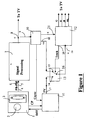
- The invention will now be described in accordance with Figure 1 which represent a schematic diagram of a part of a VCR fitted with the invention.
- A VCR according to the invention comprises a mechanical deck 1 fitted with a
drum 2 around which a cassette or a tape is wounded in a known way for about half a turn. The drum is fitted in a known way with at least a pair of magnetic heads to read and write on the tape. Each head of the pair is active in turn when it arrives on a side of the drum which is in contact with the tape. The change of head is made in a known way in accordance with a flip flop signal DFF supplied by acontrol circuit 11. The flip-flop signal DFF is elaborated on the basis of control pulses CP of the pick-up signal. In reading mode of the heads, the amplified play-back, frequency modulated signal coming from the heads known as PB-FM, is output on anoutput 4 of the mechanical deck 1 and sent through aliaison 5 to an input 6 of a signal processing circuit 7. Said processing circuit 7, is often in the form of an integrated circuit known as a video IC. Said circuit processes the PB-FM signal to extract from it the composite video blanking and syncs signal known as CVBS signal. Said CVBS signal contains the video signal and a composite synchronisation signals known as Csync. As well known the synchronisation signal is for synchronising the scanning of frame and lines of the frame of a cathode ray tube with the video signal. The Csync signal contains the vertical synchronisation pulses that form the vertical synchronisation signal known as Vsync and the horizontal synchronisation pulses that form the horizontal synchronisation signal known as Hsync. The CVBS signal is one of the output signal of the VCR. Said signal is available on an output 8 of the video IC 7. Said output is coupled in a known way to aninput 9 of asynchro separator circuit 10. Saidcircuit 10 often in the form of a dedicated IC extracts the Csync signal from the CVBS signal. The Csync signal is sent to the control circuit. In an embodiment of the invention this circuit is a microprocessor, for instance TMP90. Saidcircuit 11, among other functions elaborates from said signal a pseudo vertical synchronisation signal, PV signal. - The VCR may also output an On Screen Display signal. Said OSD signal is produced by an On Screen Display generator for instance a microcontroller. In one embodiment of the invention it is the ST92R195 microcontroller. Said On Screen Display generator is in a known way synchronised by means of the composite synchronisation signal, Csync. As explained above in trick mode the vertical synchronisation signal is jammed by spurious vertical pulses. According to the invention, in order to avoid jitter of said On Screen Display, when the VCR is in one of the trick modes the vertical synchronisation signal which is fed to the On Screen Display generator is no more the vertical synchronisation signal which is jammed, but the pseudo-vertical synchronisation signal coming from
control circuit 11. In an embodiment of the invention this change is made by means of acontrollable switch 13. Said switch 13 has three ends a first 14, a second 15, and a third 16 and two positions, a first and a second. Thefirst end 14 is coupled to anoutput 17 of thecontrol circuit 11 of thedrum 2 that receives the pseudo vertical synchronisation signal. Thesecond end 15 is coupled to anoutput 18 of the synchro-separator circuit 10 that receives the vertical conventional synchronisation signal. The third end is connected to aninput 19 of the On Screen Display generator (OSD) 12. The On Screen Display generator (OSD) 12 is as already said a dedicated circuit that has an input forecast to receive the vertical synchronisation signal. When theswitch 13 is in the first position saidthird end 16 is connected to thesecond end 15 so that it receives the vertical synchronisation signal coming from the synchro-separator circuit 10. When theswitch 13 is in the second position saidthird end 16 is connected to thefirst end 14 so that it receives the pseudo-vertical synchronisation signal. The change from one position to the other is made by a logic control signal produced by the On ScreenDisplay generator 12, and delivered on anoutput 20 ofsaid circuit 12. It could be sent from another circuit coupled to receive a piece of information meaning that the VCR is controlled to be in trick mode.
Claims (4)
- Apparatus for combining a first image and a second image, comprising :- means (1,2,7) for providing a signal representative of a first image to a screen, said signal including a vertical synchronisation signal, wherein the means for providing the signal representative of the first image includes a rotary drum fitted with at least a pair of magnetic heads for reading a magnetic tape,- generator means (12) for generating a second image, said generator means having at least an input (19) for receiving a signal to synchronise the second image with the first image.characterised in that it further includes- means (11) for providing a pseudo-vertical synchronisation signal, wherein the means for providing a pseudo vertical synchronisation signal comprise a control circuit elaborating the pseudo-vertical synchronisation signal on the basis of control pulses generated by the rotary drum,- control means (12) having an output (20) indicating the mode in which the arrangement is functioning, wherein the mode is one of normal play mode and trick mode in which the speed of the tape is different from the normal speed,- selector means (13) for selectively providing said vertical synchronisation signal or said pseudo vertical synchronisation signal to said input (19) depending on the output (20) of the control means,
- Apparatus according to claim 1, wherein the generator means comprises an On Screen Display generator.
- Apparatus according to claim 1, further including separator means for taking the vertical synchronisation signal out of the signal representative of the first image.
- Apparatus according to claim 3, wherein the selector means are in the form of a switch with a first input connected to the separator means, with a second input connected to the means for providing the pseudo-vertical synchronization signal, with a third input connected to the control means and with an output connected to the input of the generator means.
Applications Claiming Priority (2)
| Application Number | Priority Date | Filing Date | Title |
|---|---|---|---|
| GB9817189 | 1998-08-06 | ||
| GB9817189A GB2340291A (en) | 1998-08-06 | 1998-08-06 | Avoiding jitter in a video output using pseudo-vertical synchronisation signals |
Publications (3)
| Publication Number | Publication Date |
|---|---|
| EP0979006A2 EP0979006A2 (en) | 2000-02-09 |
| EP0979006A3 EP0979006A3 (en) | 2002-04-10 |
| EP0979006B1 true EP0979006B1 (en) | 2006-12-06 |
Family
ID=10836856
Family Applications (1)
| Application Number | Title | Priority Date | Filing Date |
|---|---|---|---|
| EP99401917A Expired - Lifetime EP0979006B1 (en) | 1998-08-06 | 1999-07-27 | Arrangements providing signal representative of at least two images to be displayed superimposed on a screen |
Country Status (11)
| Country | Link |
|---|---|
| US (1) | US6628888B1 (en) |
| EP (1) | EP0979006B1 (en) |
| JP (1) | JP2000069431A (en) |
| KR (1) | KR20000016932A (en) |
| CN (1) | CN1244711A (en) |
| AR (1) | AR021185A1 (en) |
| DE (1) | DE69934282T2 (en) |
| GB (1) | GB2340291A (en) |
| ID (1) | ID23763A (en) |
| MY (1) | MY125177A (en) |
| ZA (1) | ZA994638B (en) |
Families Citing this family (3)
| Publication number | Priority date | Publication date | Assignee | Title |
|---|---|---|---|---|
| KR100657255B1 (en) * | 2000-06-16 | 2006-12-14 | 삼성전자주식회사 | System for video signal processor |
| EP1176809A1 (en) * | 2000-07-28 | 2002-01-30 | THOMSON multimedia | Synchronisation circuit for a display device |
| TWI248304B (en) * | 2004-12-01 | 2006-01-21 | Tatung Co Ltd | A method for displaying dynamic design |
Family Cites Families (5)
| Publication number | Priority date | Publication date | Assignee | Title |
|---|---|---|---|---|
| JPS524013Y2 (en) * | 1972-09-29 | 1977-01-27 | ||
| US5179477A (en) * | 1989-01-21 | 1993-01-12 | Mitsubishi Denki Kabushiki | Video tape recorder |
| US6041159A (en) * | 1995-07-11 | 2000-03-21 | Deutsche Thomson-Brandt Gmbh | Telecommunications device having a remote controller |
| US6078724A (en) * | 1996-08-29 | 2000-06-20 | Victor Company Of Japan, Ltd. | Magnetic reproducing apparatus of helical scan type |
| KR100219621B1 (en) * | 1996-12-31 | 1999-09-01 | 윤종용 | Apparatus for compensating the wave of osd picture operating special functions |
-
1998
- 1998-08-06 GB GB9817189A patent/GB2340291A/en not_active Withdrawn
-
1999
- 1999-07-14 KR KR1019990028360A patent/KR20000016932A/en not_active Application Discontinuation
- 1999-07-19 ZA ZA9904638A patent/ZA994638B/en unknown
- 1999-07-26 CN CN99110677A patent/CN1244711A/en active Pending
- 1999-07-27 EP EP99401917A patent/EP0979006B1/en not_active Expired - Lifetime
- 1999-07-27 DE DE69934282T patent/DE69934282T2/en not_active Expired - Lifetime
- 1999-08-05 JP JP11222487A patent/JP2000069431A/en active Pending
- 1999-08-05 MY MYPI99003340A patent/MY125177A/en unknown
- 1999-08-05 US US09/368,508 patent/US6628888B1/en not_active Expired - Lifetime
- 1999-08-06 ID IDP990773D patent/ID23763A/en unknown
- 1999-08-06 AR ARP990103951A patent/AR021185A1/en unknown
Also Published As
| Publication number | Publication date |
|---|---|
| US6628888B1 (en) | 2003-09-30 |
| GB9817189D0 (en) | 1998-10-07 |
| EP0979006A3 (en) | 2002-04-10 |
| DE69934282T2 (en) | 2007-05-16 |
| GB2340291A (en) | 2000-02-16 |
| KR20000016932A (en) | 2000-03-25 |
| EP0979006A2 (en) | 2000-02-09 |
| ZA994638B (en) | 2000-02-22 |
| JP2000069431A (en) | 2000-03-03 |
| MY125177A (en) | 2006-07-31 |
| AR021185A1 (en) | 2002-07-03 |
| DE69934282D1 (en) | 2007-01-18 |
| CN1244711A (en) | 2000-02-16 |
| ID23763A (en) | 2000-05-11 |
Similar Documents
| Publication | Publication Date | Title |
|---|---|---|
| US4498098A (en) | Apparatus for combining a video signal with graphics and text from a computer | |
| EP0533092B1 (en) | Video camera with switchable aspect ratio | |
| US6895172B2 (en) | Video signal reproducing apparatus | |
| US5392069A (en) | Image processing apparatus which can process a plurality of kinds of images having different aspect ratios | |
| EP0979006B1 (en) | Arrangements providing signal representative of at least two images to be displayed superimposed on a screen | |
| JPS6050099B2 (en) | A device for synchronizing the playback video signal from a video disc with other video signals | |
| JPH0357382A (en) | Magnetic recorder | |
| JP2771266B2 (en) | Multi-system video signal playback and display device | |
| EP0172572B1 (en) | Televison sync signal processing circuit | |
| US5887112A (en) | Combination apparatus comprising a video-recorder section and a television-receiver section | |
| JPH06261274A (en) | Video signal recording/reproducing device | |
| MXPA99007223A (en) | Provision to overload two images without fluctuac | |
| JP2513731B2 (en) | Camera integrated video tape recorder | |
| JPH01106587A (en) | One-body type camera and vtr | |
| JP2840429B2 (en) | Video signal communication method | |
| KR0150961B1 (en) | Reference signal generation circuit of osd | |
| JP3019310B2 (en) | Automatic frequency control circuit | |
| KR820002264B1 (en) | Reproducing arrangements of pictures | |
| JPH0526873Y2 (en) | ||
| JP2578861B2 (en) | Video signal switching circuit | |
| JPS6222317B2 (en) | ||
| JPH0575916A (en) | Video camera | |
| JP2000036929A (en) | Still image recording and reproducing device | |
| JPS59111487A (en) | Character generating and inserting circuit of vtr | |
| JPH01132285A (en) | Picture memory control device |
Legal Events
| Date | Code | Title | Description |
|---|---|---|---|
| PUAI | Public reference made under article 153(3) epc to a published international application that has entered the european phase |
Free format text: ORIGINAL CODE: 0009012 |
|
| AK | Designated contracting states |
Kind code of ref document: A2 Designated state(s): AT BE CH CY DE DK ES FI FR GB GR IE IT LI LU MC NL PT SE Kind code of ref document: A2 Designated state(s): DE FR GB IT |
|
| AX | Request for extension of the european patent |
Free format text: AL;LT;LV;MK;RO;SI |
|
| PUAL | Search report despatched |
Free format text: ORIGINAL CODE: 0009013 |
|
| AK | Designated contracting states |
Kind code of ref document: A3 Designated state(s): AT BE CH CY DE DK ES FI FR GB GR IE IT LI LU MC NL PT SE |
|
| AX | Request for extension of the european patent |
Free format text: AL;LT;LV;MK;RO;SI |
|
| 17P | Request for examination filed |
Effective date: 20021003 |
|
| AKX | Designation fees paid |
Free format text: DE FR GB IT |
|
| GRAP | Despatch of communication of intention to grant a patent |
Free format text: ORIGINAL CODE: EPIDOSNIGR1 |
|
| GRAS | Grant fee paid |
Free format text: ORIGINAL CODE: EPIDOSNIGR3 |
|
| GRAA | (expected) grant |
Free format text: ORIGINAL CODE: 0009210 |
|
| AK | Designated contracting states |
Kind code of ref document: B1 Designated state(s): DE FR GB IT |
|
| REG | Reference to a national code |
Ref country code: GB Ref legal event code: FG4D |
|
| REF | Corresponds to: |
Ref document number: 69934282 Country of ref document: DE Date of ref document: 20070118 Kind code of ref document: P |
|
| REG | Reference to a national code |
Ref country code: GB Ref legal event code: 746 Effective date: 20070125 |
|
| ET | Fr: translation filed | ||
| PLBE | No opposition filed within time limit |
Free format text: ORIGINAL CODE: 0009261 |
|
| STAA | Information on the status of an ep patent application or granted ep patent |
Free format text: STATUS: NO OPPOSITION FILED WITHIN TIME LIMIT |
|
| 26N | No opposition filed |
Effective date: 20070907 |
|
| PGFP | Annual fee paid to national office [announced via postgrant information from national office to epo] |
Ref country code: DE Payment date: 20150723 Year of fee payment: 17 |
|
| REG | Reference to a national code |
Ref country code: FR Ref legal event code: PLFP Year of fee payment: 18 |
|
| PGFP | Annual fee paid to national office [announced via postgrant information from national office to epo] |
Ref country code: GB Payment date: 20160720 Year of fee payment: 18 Ref country code: IT Payment date: 20160720 Year of fee payment: 18 |
|
| PGFP | Annual fee paid to national office [announced via postgrant information from national office to epo] |
Ref country code: FR Payment date: 20160726 Year of fee payment: 18 |
|
| REG | Reference to a national code |
Ref country code: DE Ref legal event code: R119 Ref document number: 69934282 Country of ref document: DE |
|
| PG25 | Lapsed in a contracting state [announced via postgrant information from national office to epo] |
Ref country code: DE Free format text: LAPSE BECAUSE OF NON-PAYMENT OF DUE FEES Effective date: 20170201 |
|
| GBPC | Gb: european patent ceased through non-payment of renewal fee |
Effective date: 20170727 |
|
| REG | Reference to a national code |
Ref country code: FR Ref legal event code: ST Effective date: 20180330 |
|
| PG25 | Lapsed in a contracting state [announced via postgrant information from national office to epo] |
Ref country code: GB Free format text: LAPSE BECAUSE OF NON-PAYMENT OF DUE FEES Effective date: 20170727 |
|
| PG25 | Lapsed in a contracting state [announced via postgrant information from national office to epo] |
Ref country code: FR Free format text: LAPSE BECAUSE OF NON-PAYMENT OF DUE FEES Effective date: 20170731 |
|
| PG25 | Lapsed in a contracting state [announced via postgrant information from national office to epo] |
Ref country code: IT Free format text: LAPSE BECAUSE OF NON-PAYMENT OF DUE FEES Effective date: 20170727 |