EP0978632A1 - Turbomachine with intermediate blades as flow dividers - Google Patents
Turbomachine with intermediate blades as flow dividers Download PDFInfo
- Publication number
- EP0978632A1 EP0978632A1 EP98810756A EP98810756A EP0978632A1 EP 0978632 A1 EP0978632 A1 EP 0978632A1 EP 98810756 A EP98810756 A EP 98810756A EP 98810756 A EP98810756 A EP 98810756A EP 0978632 A1 EP0978632 A1 EP 0978632A1
- Authority
- EP
- European Patent Office
- Prior art keywords
- blade
- full
- channel
- flow
- blades
- Prior art date
- Legal status (The legal status is an assumption and is not a legal conclusion. Google has not performed a legal analysis and makes no representation as to the accuracy of the status listed.)
- Withdrawn
Links
Images


Classifications
-
- F—MECHANICAL ENGINEERING; LIGHTING; HEATING; WEAPONS; BLASTING
- F01—MACHINES OR ENGINES IN GENERAL; ENGINE PLANTS IN GENERAL; STEAM ENGINES
- F01D—NON-POSITIVE DISPLACEMENT MACHINES OR ENGINES, e.g. STEAM TURBINES
- F01D5/00—Blades; Blade-carrying members; Heating, heat-insulating, cooling or antivibration means on the blades or the members
- F01D5/12—Blades
- F01D5/14—Form or construction
- F01D5/141—Shape, i.e. outer, aerodynamic form
- F01D5/145—Means for influencing boundary layers or secondary circulations
Definitions
- the invention relates to devices for reducing the losses of a fluid flow in bladed flow channels of turbomachinery, especially in steam or Gas turbines.
- the efficiency of a turbomachine, especially one, that is common today Steam or gas turbine, to further increase it is central to that the flow through the bladed flow channels of the turbomachine To reduce flow losses of the fluid.
- a row of blades arranged on the circumference of a turbomachine is used commonly referred to as a grid.
- the blades of a grid hereinafter referred to as Full buckets are generally all designed in the same way.
- a Turbomachine usually consists of an arrangement of several stationary and moving grids arranged one behind the other. Two full blades arranged side by side together with the flow-limiting side walls form a vane channel.
- modern grids in turbines are mostly called 'aft-loaded' load-balanced execution, d. that is, the speed distribution of the Flow along the suction surface of a turbine blade in the rear Half of the full blade considered in the flow direction has a maximum.
- the maximum speed occurs in a good approximation in the smallest geometric plane Flow cross-section of the blade channel under consideration.
- At maximum Flow velocity has a minimal static pressure on the flow profile surface of the full blade on the suction side.
- the flow losses occur particularly in the suction-side areas Blade channel near the hub and the housing.
- the cause of the increase in Flow loss is on the one hand the meeting of the flow boundary layers both the blade profile and the side walls in the corner areas of the to consider the blade channel considered. This leads to a local thickening of the Boundary layer in the corner areas of the blade channel.
- the deflection of the flow in the vane channel a pressure gradient and thus a pressure and a suction side of the blade channel. Because of this pressure gradient from the Pressure side to suction side of adjacent blades occurs in this blade channel a constant drift of boundary layer material towards the suction side. This will the channel vortex intensifies, which ultimately results in an increase in flow losses Has.
- the mutual superposition of the occurring flow phenomena thus leads to highly three-dimensional currents.
- the invention has for its object to flow losses through the fluid flow to reduce a turbomachine, in particular by an axially flowed through turbine. This object is achieved in that at least one flow-limiting side wall of the turbomachine between two full blades at least one intermediate blade is arranged.
- This equalizing flow represents a secondary flow and runs predominantly within the boundary layers, which leads to an accumulation of energetically deficient boundary layer fluids in the side wall and profile boundary layers on the suction side. In addition, it increases with excessive accumulation of the boundary layer fluid on the suction side by screwing it in of the energetically deficient boundary layer fluid of the channel vortex.
- the invention comes in. Due to the arrangement according to the invention at least one Intermediate blade on at least one flow-limiting wall between two When the blades are full, the blade channel is locally divided into at least two subchannels. The The height of the intermediate blade is smaller than that of the full blade. Thus extends the intermediate blade does not extend over the entire height of the blade channel. Consequently the blade channel becomes only up to the height due to the arrangement of the intermediate blade the intermediate blade divided.
- the intermediate blades can expediently on the hub-side and / or the be arranged side walls of the blade channels of a turbomachine. As an alternative to this, it can also be advantageous if several are provided per side wall Intermediate blades are grouped, which locally divide the blade channel into several, equally large Subdivide subchannels.
- the arrangement of intermediate blades is preferably carried out in all Blade channels of a flow grid in the same way.
- the invention is based on the assumption that the full blades within one Flow grids have the same profile contours. But this does not constitute Basic requirement for the use of intermediate blades.
- the intermediate blades can also in blade channels between differently contoured full blades be used.
- the height of the intermediate blade for the implementation of the invention is essential.
- the intermediate blade has a height between approximately 3% and approximately 10% of the height of a of the full blades forming the blade channel. This height is preferred in Depending on the blade height ratio H / s to choose the full blade, the The height of the intermediate blade is preferably about 3% with a large blade height ratio H / s and about 10% with a small blade height ratio H / s of the height H of the full blade is.
- H stands for the height of the full bucket and s for the chord length of the Full bucket. The ratio of the height of the intermediate blade to that Bucket height ratio of the full bucket is therefore opposite.
- Bucket height ratios are consequently preferably in relation to the Full blades to arrange small intermediate blades and vice versa.
- Size Bucket height ratios mostly occur in the medium and low pressure range of a steam or gas turbine, but small blade height ratios often in High pressure area of a steam or gas turbine. It turned out that the arrangement of a Intermediate blade, with a height corresponding to the preferred embodiment is carried out, leads to an optimal reduction of the total losses of the flow. On the one hand, a height selected in this way is sufficient by which there is in the boundary layer effectively prevent secondary flow. On the other hand, the Profile losses due to small, additionally overflowed wall surfaces of the intermediate blade only slightly.
- the intermediate blade with a very small blade thickness to execute.
- the maximum profile thickness d 'of the intermediate blade is preferably between about 2% and about 10% of the maximum profile thickness d of the full blades, in Depending on the blade thickness ratio d / s of the solid blades, preferably about 2% with a large blade thickness ratio and approximately 10% with a small blade thickness ratio.
- a small blade thickness of the intermediate blade only a small one occurs Displacement effect through the intermediate blade. This minor Displacement leads to only a slight increase in profile losses Intermediate blade. These profile losses are therefore significantly lower than the profile losses a full bucket of comparable height.
- the blade nose of the intermediate blade is opposite the blade nose of the To move full blades in the blade channel downstream, i.e. set back.
- the blade nose is preferably set back relative to the intermediate blade the blade lugs of the solid blades with an offset V, the offset V is between 3% and 10% of the axial chord length T of a full blade.
- the Displacement V is here the distance of the recessed blade nose to that To determine blade noses of straight lines connecting full blades.
- the extension of the intermediate blade in the blade channel should preferably be chosen so that that the rear edge of the intermediate blade against the rear edges of the full blades in an area between the aligned arrangement of the rear edges (corresponds to 0% Dislocation) and a maximum dislocation is arranged upstream.
- the maximal Displacement of the trailing edge of the intermediate blade upstream i.e. the maximal Forward offset of the rear edge, here is 120% of the distance between the aligned arranged trailing edge to the narrowest cross section of the blade channel. These distances are to be determined as perpendicular to the narrowest cross-section of the blade channel.
- the offset of the rear edge of the intermediate blade is particularly preferred between 100% and 120% of the distance of the aligned rear edges to the narrowest cross section of the blade channel and particularly preferably between 110% and 120%.
- This preferred arrangement of the rear edge of the intermediate blade compared to an aligned rear edge is an improved flow of to name the next row of blades. This advantage is achieved because the Bucket channel emerging, caused by the intermediate blades trailing dents in the pressure curve of the fluid flow due to the acceleration of the flow up to narrowest cross section of the blade channel can be reduced. This leads to less dissipative flow losses.
- turbo machines can be used relatively easily the intermediate blades according to the invention can be retrofitted. This is just appropriate grooves in the side walls. To the same Ensuring mass throughput through an affected blade channel is not necessary to change the existing blading, because the narrowest cross section of the Blade channel remains intact.
- the trailing edge of the intermediate blade is offset particularly preferably between 0% and 40% of the distance between the aligned Trailing edges to the narrowest cross section of the blade channel and particularly preferred between 10% and 20%.
- the intermediate blade in the narrowest areas in particular Cross-section of the blade channel approximately in the center, preferably between 40% and 60% of the narrowest cross section of the blade channel, to be arranged in the blade channel.
- Cross-section of the subchannel facing the suction side of the full blade approximately half of the narrowest cross-section of the blade channel, preferably between 40% and 60% of the narrowest cross section of the blade channel. The latter only applies if the Trailing edge of the intermediate blade not in areas upstream of the narrowest cross section of the Blade channel is offset.
- the suction side of the To profile the intermediate blade in the same way or approximately in the same way as the suction sides of the full blades.
- the assignment of the profile contours of the intermediate blade to the full blades takes place via the axial position in the blade channel. It showed yourself that the profile losses of the intermediate blade in a special degree of profile contour on the suction side. In connection with the low Profile thickness of the intermediate blade thus results in a profile contour on the pressure side Intermediate blade that deviates from the pressure-side profile contours of the full blades.
- the through the intermediate blade and the side wall formed corners are in the longitudinal direction of the sub-channels, however but preferably carried out at right angles.
- the intermediate blade is particularly advantageous to divide the intermediate blade into segments.
- the Segments of the intermediate blade can thus be separated from one another on one or multiple platforms can be arranged.
- a division of an intermediate blade Two platforms can occur, for example, if the parting line between two Platforms are arranged approximately centrally in the blade channel and the Intermediate blade is also preferably positioned centrally.
- the intermediate blade or the segments are the Intermediate bucket with the respective platform made in one piece.
- This one-piece Components can be manufactured inexpensively, for example, by casting.
- the intermediate blade and the platform can also be advantageous to be manufactured separately.
- One or more grooves in the platform are preferred incorporated.
- the intermediate blade can thus be suitably in these grooves be attached.
- the attachment of the intermediate blades can also be advantageous in this way, if the side walls are not made of lined-up platforms, but are formed from a circular ring.
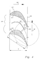
- the arrangement shown in FIG. 1 shows a hole-shaped flow channel 120 in the front view.
- the flow channel 120 has an inner (hub side) flow-limiting side wall 122 and an outer (housing side) flow-limiting side wall 123.
- two are in the Flow channels 120 arranged full blades 130, 130 'shown.
- the full shovels 130, 130 ' are aligned radially, with the extended central axes 124 of the Full blades 130, 130 'at the center 121 or near the center 121 of the Cut flow channel 120.
- the full blades 130, 130 ' have a height H on.
- the full blades 130, 130 'arranged in the flow channel limit one Blade channel 160.
- the blade channel 160 shown in FIG. 1 corresponds here to one Blade channel of a flow grid of an axially flowed through turbomachine.
- both on the hub side and on the housing side flow-limiting side wall 122, 123 each have an intermediate blade 150, 155 arranged.
- the intermediate blades 150, 155 are radially aligned in the same way as the full blades 130, 130 '.
- the intermediate blades 150, 155 are of a smaller size Height h as the full blades.
- the height h of the intermediate blades 150, 155 in Figure 1 corresponds to about 10% of the height H of the full blades 130, 130 '.
- the Intermediate blades 150, 155 could also be designed with different heights. It turned out that with a view to an optimal reduction of the Flow losses the height h of the intermediate blade is an important influencing variable.
- the blade channel 160 becomes dependent on the arrangement of the intermediate blades 150, 155 each locally divided into two subchannels 170, 171 and 180, 181.
- the corners of the subchannels between the intermediate blade and the side wall in the longitudinal direction of the subchannels executed at right angles in the embodiment according to FIG.
- FIG. 2 shows a top view of a section through a blade channel 60, which is part of the prior art.
- the blade channel 60 is shown in simplified form as a section of a grating developed in the plane.
- the circumferential direction of the grating arranged on the circumference of a machine thus corresponds to the longitudinal direction 91 of the grating in the illustration.
- the blade channel 60 is delimited in the longitudinal direction 91 of the grid by the full blades 30 and 30 '.
- the full blades 30, 30 ' are geometrically identical here.
- the axial chord length T of the solid blades 30, 30 'and the chord length s of the solid blades 30, 30' are shown as the geometric sizes of the solid blades 30, 30 '.
- the respective profile thickness results from fitting circles into the profile contour of the blade.
- the maximum profile thickness thus represents the diameter of the largest circle that fits the profile contour.
- the maximum profile thickness of the full blades 30, 30 ' is marked with d.
- the blade thickness ratio d / s and the blade height ratio H / s can be defined on the basis of the geometric size definitions of the full blades 30, 30 ′ listed above.
- the narrowest cross section 65 of the blade channel 60 is characterized by the distance between A and B ".
- the grid shown in Figure 2 is designed here as a turbine grid.
- the scoop channel 60 consequently exhibits a continuous narrowing of the channel cross-section from the entrance to the exit of the blade channel 60.
- the blade channel 60 is flowed against by fluid in accordance with the flow direction 12.
- the Fluid enters the blade channel 60 and here follows the blade profile redirected.
- This flow following the blade profile is called the primary flow 10 designated.
- This Pressure gradient within the blade channel 60 leads to the formation of a Secondary flow 11 mainly in the sidewall boundary layer. Based on these Secondary flow 11 also leads to the fusing of the channel vortex 11 '.
- corner vertebrae 11 "occur along the corners of the blade channel. This as Secondary flows designated flow forms 11, 11 ', 11' 'lead to high Loss of fluid flow through the blade channel.
- FIG. 3 shows a blade channel 160 in the same sectional view as in FIG. 2, in which an intermediate blade 150 is arranged according to the invention.
- the inflow 112 the grid is shown from the left.
- an intermediate blade 150 is approximately centered in the blade channel 160 arranged.
- the blade channel 160 divided into two sub-channels 180, 181. It was found that the losses in the Flow through the blade channel in the sum of the losses of the sub-channels 180, 181 Arrangement of the intermediate blade 150 in the blade channel 160 opposite the Arrangement without an intermediate blade can be significantly reduced.
- the blade nose 153 of the intermediate blade 150 is in this embodiment of the invention set back by an axial distance V.
- the setback of the blade nose 153 the intermediate blade 150 relates to the straight line connecting the blade lugs 133, 133 'of the full blades 130, 130', i.e. the front line 195 of the grille.
- the Reset V is here in a particularly preferred embodiment of the invention about 5% of the axial chord length T of the full blades 130, 130 '.
- the intermediate blade 150 in FIG. 3 has a small maximum profile thickness d ' Intermediate blade 150 executed.
- This maximum professional thickness d ' corresponds here to about 10% the maximum profile thickness d of the full blades 130, 130 '.
- the suction side 152 of the intermediate blade 150 in the exemplary embodiment Execution of the invention has approximately the same profile contour profile as that Suction side 132 of the full blade 130.
- the profile contours are assigned here via the axial position in the blade channel 160.
- the radius of curvature R 'on the suction side the intermediate blade 150 here the radius of curvature R of the full blade on the suction side 130 in the area after the narrowest cross section (A'B ') of the subchannel between the Full blade 130 and the intermediate blade 150.
- the intermediate blade 150 in FIG. 3 is in the blade channel 160 between the Full blades 130, 130 ′ are arranged such that the rear edge 154 of the intermediate blade 150 to be in alignment with the trailing edges B and B "of the full blades 130, 130 ' is coming.
- the fluid flow is thus in the area of the subchannel 180 between A "and B ' guided on both sides.
- the aerodynamic load of the Full bucket diminishes as well as the point of highest aerodynamic Load of the blade profile in the blade channel 160 is shifted downstream. Farther there is a reduction in secondary flow losses and beyond an increase in the deflection of the primary flow in the vane duct 160.
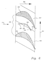
- the trailing edge 254 is advantageously offset upstream of the narrowest cross section (AB ") of the blade channel 260.
- the narrowest cross section (AB") of the blade channel 260 is thereby not reduced.
- the area of the rear edge 254 of the intermediate blade 250 is shown enlarged in FIG.
- the offset q x of the rear edge 254 here is approximately 110% of the distance q 1 .
- the distance q 1 is defined as the distance between the non-offset rear edge B 'of the intermediate blade 250, which is arranged in alignment with the rear edges B and B "of the full blades, and the narrowest cross section (AB") of the blade channel.
- Both the distance q 1 and q x are to be measured perpendicular to the narrowest cross-section (AB ") of the blade channel.
- To determine the distance use the auxiliary line labeled ⁇ through point B ', which is parallel to the narrowest cross-section (AB") is registered.
- the intermediate blade in one piece with the side wall. This can be realized, for example, by casting or machining.
- the Side walls of the bladed flow channels in turbomachinery often arise by lining up rhombic platforms. These platforms are often made in one piece with the full blades.
- Figure 6 shows such an arrangement two platforms 326 and 327.
- the platforms 326, 327 lined up here form a side wall of the blade channel 360.
- the parting line 328 between the platforms In the embodiment shown in FIG. 6, 326 and 327 is centered in the blade channel 360 arranged.
- the intermediate blade 350 is also approximately in the middle here Blade channel 360 positioned.
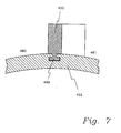
- Figure 7 shows an embodiment of the invention, in which the intermediate blade 450 in a T-groove 499 is arranged on the side wall 422.
- This arrangement is especially then useful if the flow-limiting side wall and the intermediate blade as separate parts were manufactured.
Landscapes
- Engineering & Computer Science (AREA)
- Physics & Mathematics (AREA)
- Fluid Mechanics (AREA)
- Mechanical Engineering (AREA)
- General Engineering & Computer Science (AREA)
- Turbine Rotor Nozzle Sealing (AREA)
Abstract
Description
Die Erfindung betrifft Vorrichtungen zur Reduzierung der Verluste einer Fluidströmung in beschaufelten Strömungskanälen von Turbomaschinen, insbesondere in Dampf- oder Gasturbinen.The invention relates to devices for reducing the losses of a fluid flow in bladed flow channels of turbomachinery, especially in steam or Gas turbines.
Um die heutzutage üblichen Wirkungsgrade einer Turbomaschine, insbesondere einer Dampf- oder Gasturbine, noch weiter zu steigern, ist es von zentraler Bedeutung, die bei der Durchströmung der beschaufelten Strömungskanäle der Turbomaschine auftretenden Strömungsverluste des Fluides zu verringern.The efficiency of a turbomachine, especially one, that is common today Steam or gas turbine, to further increase it is central to that the flow through the bladed flow channels of the turbomachine To reduce flow losses of the fluid.
Die bei der Durchströmung eines beschaufelten Strömungskanals einer Turbomaschine auftretenden Strömungsverluste setzen sich maßgeblich einerseits aus Profil- und Seitenwandverlusten sowie andererseits aus Sekundärströmungsverlusten der Fluidströmung zusammen. Profil- und Seitenwandverluste ergeben sich als Folge der Ausbildung von Strömungsgrenzschichten des viskosen Strömungsfluides beim Überströmen von Bauteilwandungen. Unter Sekundärströmungen werden alle von der primären, potentialtheoretisch zu betrachtenden Strömung abweichenden Strömungen, insbesondere Wirbelströmungen, verstanden, wie z. B. Ausgleichsströmungen zwischen der Druck- und Saugseite eines Schaufelkanals sowie der Kanalwirbel, der Hufeisenwirbel, der Hinterkantenwirbel, der Eckenwirbel und der Spaltwirbel.The flow through a bladed flow channel of a turbomachine Flow losses that occur are largely composed of profile and Sidewall losses and on the other hand from secondary flow losses Fluid flow together. Profile and side wall losses result as a result of Formation of flow boundary layers of the viscous flow fluid in Overflow of component walls. Under secondary flows, all of the primary currents deviating currents to be considered, in particular eddy currents, understood such. B. equalizing flows between the pressure and suction side of a blade channel as well as the channel vortex, the horseshoe vortex, the trailing edge vertebra, the corner vertebra and the cleft vertebra.
Eine am Umfang einer Turbomaschine angeordnete Reihe von Schaufeln wird üblicherweise als Gitter bezeichnet. Die Schaufeln eines Gitters, im Folgenden als Vollschaufeln bezeichnet, sind in der Regel alle in gleicher Weise ausgeführt. Eine Turbomaschine besteht zumeist aus einer Anordnung mehrerer feststehender und bewegter, hintereinander angeordneter Gitter. Je zwei nebeneinander angeordnete Vollschaufeln bilden zusammen mit den strömungsbegrenzenden Seitenwänden einen Schaufelkanal.A row of blades arranged on the circumference of a turbomachine is used commonly referred to as a grid. The blades of a grid, hereinafter referred to as Full buckets are generally all designed in the same way. A Turbomachine usually consists of an arrangement of several stationary and moving grids arranged one behind the other. Two full blades arranged side by side together with the flow-limiting side walls form a vane channel.
Neben dem Grad der Umlenkung des Strömungsfluides bestimmt insbesondere die Profilierung der Vollschaufeln eines jeden Gitters sowohl in Schaufellängs- als auch in Schaufelhöhenrichtung und somit die lokale Strömungsführung das Verlustverhalten der einzelnen Gitterströmungen. Moderne Gitter in Turbinen werden heutzutage zumeist als 'aft-loaded' belastungsverteilt ausgeführt, d. h., daß die Geschwindigkeitsverteilung der Strömung entlang der saugseitigen Profiloberfläche einer Turbinenschaufel in der hinteren Hälfte der in Strömungsrichtung betrachteten Vollschaufel ein Maximum aufweist. Die maximale Geschwindigkeit tritt in guter Näherung in der Ebene kleinsten geometrischen Strömungsquerschnittes des betrachteten Schaufelkanals auf. Bei maximaler Strömungsgeschwindigkeit weist die Strömung einen minimalen statischen Druck auf der saugseitigen Profiloberfläche der Vollschaufel auf. Hieran schließt sich eine Diffusion der Strömung auf der Saugseite der Vollschaufel bis zur Hinterkante hin an, wodurch die Geschwindigkeit der Strömung abnimmt. Dies führt zu einem Anstieg des statischen Druckes entlang des saugseitigen Profils der Voll schaufeln stromab des engsten Querschnitts des Schaufelkanals. Die Strömung muß somit in diesem Bereich gegen einen positiven Druckgradienten anströmen. Neben einem verstärkten Anwachsen der Grenzschicht entlang des Schaufelprofils resultiert hieraus eine höhere Ablösegefahr der saugseitigen Strömung im Bereich der Hinterkante. Beide Effekte wiederum haben sowohl eine Zunahme der reibungsbedingten Verluste der Strömung als auch eine Zunahme der Deviation des Abströmwinkels des Gitters zur Folge.In addition to the degree of deflection of the flow fluid, the Profiling the full blades of each grating both in the blade longitudinal and in Blade height direction and thus the local flow control the loss behavior of the individual lattice flows. Today, modern grids in turbines are mostly called 'aft-loaded' load-balanced execution, d. that is, the speed distribution of the Flow along the suction surface of a turbine blade in the rear Half of the full blade considered in the flow direction has a maximum. The maximum speed occurs in a good approximation in the smallest geometric plane Flow cross-section of the blade channel under consideration. At maximum Flow velocity has a minimal static pressure on the flow profile surface of the full blade on the suction side. This is followed by a diffusion of the Flow on the suction side of the full bucket up to the rear edge, whereby the Velocity of the flow decreases. This leads to an increase in static Pressure along the suction side profile of the full blades downstream of the narrowest Cross-section of the blade channel. The flow must therefore be against you in this area flow to positive pressure gradients. In addition to an increased growth of Boundary layer along the blade profile results in a higher risk of detachment suction-side flow in the area of the rear edge. Both effects have both an increase in frictional flow losses as well as an increase in Deviation of the outflow angle of the grille results.
Die Strömungsverluste treten verstärkt insbesondere in den saugseitigen Bereichen eines Schaufelkanals nahe der Nabe und des Gehäuses auf. Als Ursache für die Zunahme der Strömungsverluste ist einerseits das Aufeinandertreffen der Strömungsgrenzschichten sowohl des Schaufelprofils als auch der Seitenwände in den Eckenbereichen des betrachteten Schaufelkanals zu nennen. Dies führt zu einer lokalen Aufdickung der Grenzschicht in den Eckenbereichen des Schaufelkanals. Andererseits bildet sich infolge der Umlenkung der Strömung im Schaufelkanal ein Druckgradient und somit eine Druck- und eine Saugseite des Schaufelkanals aus. Aufgrund dieses Druckgradienten von der Druckseite zur Saugseite benachbarter Schaufeln kommt es in diesem Schaufelkanal zu einer ständigen Drift von Grenzschichtmaterial in Richtung der Saugseite. Dadurch wird der Kanalwirbel verstärkt, was letztlich eine Erhöhung der Strömungsverluste zur Folge hat. Die gegenseitige Überlagerung der auftretenden Strömungsphänomene führt somit zu hochgradig dreidimensionalen Strömungen.The flow losses occur particularly in the suction-side areas Blade channel near the hub and the housing. As the cause of the increase in Flow loss is on the one hand the meeting of the flow boundary layers both the blade profile and the side walls in the corner areas of the to consider the blade channel considered. This leads to a local thickening of the Boundary layer in the corner areas of the blade channel. On the other hand, forms as a result the deflection of the flow in the vane channel a pressure gradient and thus a pressure and a suction side of the blade channel. Because of this pressure gradient from the Pressure side to suction side of adjacent blades occurs in this blade channel a constant drift of boundary layer material towards the suction side. This will the channel vortex intensifies, which ultimately results in an increase in flow losses Has. The mutual superposition of the occurring flow phenomena thus leads to highly three-dimensional currents.
Moderne Beschaufelungskonzepte versuchen diesen Überlegungen dadurch Rechnung zu tragen, daß der Verlauf der aerodynamischen Belastung über der Schaufelhöhe der Vollschaufel ein den Strömungsverhältnissen angepaßtes Belastungsprofil aufweist. Diese dreidimensional konturierten Schaufeln sind aber in der Herstellung extrem teuer. Zudem erfolgt die Anpassung der aerodynamischen Belastung durch Entlastung der kritischen Gebiete und stellt somit lokal kein Zugewinn sondern eine Verringerung der Umlenkung und somit der Leistungsdichte dar.Modern blading concepts try to take these considerations into account wear that the course of the aerodynamic load over the blade height of the Full bucket has a load profile adapted to the flow conditions. This three-dimensional contoured blades are extremely expensive to manufacture. In addition the aerodynamic load is adjusted by relieving the critical load Territories and thus represents no local gain but a reduction in redirection and thus the power density.
Alternativ hierzu können am Umfang einer Turbomaschine zahlenmäßig mehr Vollschaufeln eingesetzt werden. Dies führt zu einer Verringerung des Abstandes zwischen der Druck- und der Saugseite in einem Schaufelkanal und hierdurch zu geringeren Druckunterschieden. Hieraus resultieren zwar geringere sekundärströmungsbedingte Verluste der Gitterströmung; die zunehmenden Profilverluste übersteigen jedoch den Zugewinn.Alternatively, more can be done on the circumference of a turbomachine Full blades are used. This leads to a reduction in the distance between the pressure side and the suction side in a vane channel and thereby reduced Pressure differences. This does result in lower secondary flow-related ones Grid flow losses; the increasing profile losses, however, exceed the Gain.
Der Erfindung liegt die Aufgabe zugrunde, die Strömungsverluste der Fluidströmung durch eine Turbomaschine, insbesondere durch eine axial durchströmte Turbine, zu vermindern. Diese Aufgabe wird erfindungsgemäß dadurch gelöst, daß zumindest an einer strömungsbegrenzenden Seitenwand der Turbomaschine zwischen zwei Vollschaufeln zumindest eine Zwischenschaufel angeordnet ist.The invention has for its object to flow losses through the fluid flow to reduce a turbomachine, in particular by an axially flowed through turbine. This object is achieved in that at least one flow-limiting side wall of the turbomachine between two full blades at least one intermediate blade is arranged.
Es ist bekannt, daß die höchsten Strömungsverluste einer Fluidströmung bei Durchströmen der Beschaufelung einer Turbomaschine in einem Schaufelkanal überwiegend auf den Saugseiten der Vollschaufeln auftreten. Über der Schaufelhöhe weisen hierbei die Bereiche nahe den naben- und gehäuseseitig strömungsbegrenzenden Seitenwänden das höchste Verlustverhalten auf. Als Ursache für diese Strömungsverluste sind die hochgradig dreidimensionalen Strömungsverhältnisse in diesen Bereichen, insbesondere in den saugseitigen Ecken des jeweils betrachteten Schaufelkanals, zu nennen. Diese dreidimensionalen Strömungsverhältnisse wiederum haben eine maßgebliche Ursache in dem Druckgradienten zwischen der Druck- und der Saugseite des Schaufelkanals. Der Druckgradient resultiert aus der Umlenkung der Fluidströmung in dem Schaufelkanal. Infolge dieses Druckgradienten bildet sich wiederum eine Ausgleichsströmung zwischen der Druck- und der Saugseite eines jeden Schaufelkanals aus. Diese Ausgleichsströmung stellt eine Sekundärströmung dar und verläuft überwiegend innerhalb der Grenzschichten, wodurch es zu einer Anhäufung energetisch defizitären Grenzschichtfluides in den saugseitigen Seitenwand- und Profilgrenzschichten kommt. Darüber hinaus verstärkt sich bei übermäßiger Anhäufung des Grenzschichtfluides auf der Saugseite durch ein Eindrehen des energetisch defizitären Grenzschichtfluides der Kanalwirbel.It is known that the highest flow losses of a fluid flow when flowing through the blading of a turbomachine in a blade duct predominantly on the Suction sides of the full blades occur. The areas point above the bucket height the highest near the hub and housing side flow-limiting side walls Loss behavior on. The cause of these flow losses is high three-dimensional flow conditions in these areas, especially in the corners on the suction side of the blade channel in question. This three-dimensional flow conditions in turn have a major cause in the pressure gradient between the pressure and the suction side of the blade channel. The Pressure gradient results from the deflection of the fluid flow in the blade channel. As a result of this pressure gradient, a compensating flow is formed between the pressure and suction side of each blade channel. This equalizing flow represents a secondary flow and runs predominantly within the boundary layers, which leads to an accumulation of energetically deficient boundary layer fluids in the side wall and profile boundary layers on the suction side. In addition, it increases with excessive accumulation of the boundary layer fluid on the suction side by screwing it in of the energetically deficient boundary layer fluid of the channel vortex.
Hier setzt die Erfindung an. Durch die erfindungsgemäße Anordnung zumindest einer Zwischenschaufel an zumindest einer strömungsbegrenzenden Wand zwischen zwei Vollschaufeln wird der Schaufelkanal lokal in mindestens zwei Teilkanäle unterteilt. Die Zwischenschaufel ist in ihrer Höhe kleiner ausgeführt als die Vollschaufel. Somit erstreckt sich die Zwischenschaufel nicht über die gesamte Höhe des Schaufelkanals. Infolgedessen wird der Schaufelkanal durch die Anordnung der Zwischenschaufel nur bis zu der Höhe der Zwischenschaufel unterteilt. This is where the invention comes in. Due to the arrangement according to the invention at least one Intermediate blade on at least one flow-limiting wall between two When the blades are full, the blade channel is locally divided into at least two subchannels. The The height of the intermediate blade is smaller than that of the full blade. Thus extends the intermediate blade does not extend over the entire height of the blade channel. Consequently the blade channel becomes only up to the height due to the arrangement of the intermediate blade the intermediate blade divided.
Die Zwischenschaufeln können zweckmäßig an den nabenseitigen und/oder den gehäuseseitigen Seitenwänden der Schaufelkanäle einer Turbomaschine angeordnet sein. Alternativ hierzu kann es auch von Vorteil sein, wenn je Seitenwand mehrere Zwischenschaufeln gruppiert werden, die den Schaufelkanal lokal in mehrere, gleich große Teilkanäle unterteilen. Bevorzugt erfolgt die Anordnung von Zwischenschaufeln in allen Schaufelkanälen eines Strömungsgitters in gleicher Weise. Im Rahmen der Beschreibung der Erfindung wird davon ausgegangen, daß die Vollschaufeln innerhalb eines Strömungsgitters gleiche Profilkonturen aufweisen. Dies stellt aber keine Grundvoraussetzung für den Einsatz von Zwischenschaufeln dar. Die Zwischenschaufeln können auch in Schaufelkanälen zwischen unterschiedlich konturierten Vollschaufeln eingesetzt werden.The intermediate blades can expediently on the hub-side and / or the be arranged side walls of the blade channels of a turbomachine. As an alternative to this, it can also be advantageous if several are provided per side wall Intermediate blades are grouped, which locally divide the blade channel into several, equally large Subdivide subchannels. The arrangement of intermediate blades is preferably carried out in all Blade channels of a flow grid in the same way. As part of the description The invention is based on the assumption that the full blades within one Flow grids have the same profile contours. But this does not constitute Basic requirement for the use of intermediate blades. The intermediate blades can also in blade channels between differently contoured full blades be used.
Es hat sich gezeigt, daß die Höhe der Zwischenschaufel für die Ausführung der Erfindung von wesentlicher Bedeutung ist. In einer bevorzugten Ausführungsform der Erfindung weist die Zwischenschaufel eine Höhe zwischen etwa 3% und etwa 10% der Höhe einer der den Schaufelkanal bildenden Vollschaufeln auf. Diese Höhe ist bevorzugt in Abhängigkeit des Schaufelhöhenverhältnisses H/s der Vollschaufel zu wählen, wobei die Höhe der Zwischenschaufel bevorzugt etwa 3% bei großem Schaufelhöhenverhältnis H/s und etwa 10% bei kleinem Schaufelhöhenverhältnis H/s der Höhe H der Vollschaufel beträgt. H steht hierbei für die Höhe der Vollschaufel und s für die Sehnenlänge der Vollschaufel. Das Verhältnis der Höhe der Zwischenschaufel zu dem Schaufelhöhenverhältnis der Vollschaufel ist somit gegenläufig. In Schaufelkanälen zwischen langen und schlanken Vollschaufeln, die somit ein großes Schaufelhöhenverhältnis aufweisen, sind infolgedessen vorzugsweise in Relation zu den Vollschaufeln kleine Zwischenschaufeln anzuordnen und umgekehrt. Große Schaufelhöhenverhältnisse treten zumeist im Mittel- und Niederdruckbereich einer Dampf- oder Gasturbine auf, kleine Schaufelhöhenverhältnisse hingegen oftmals im Hochdruckbereich einer Dampf- oder Gasturbine. Es zeigte sich, daß die Anordnung einer Zwischenschaufel, die mit einer der bevorzugten Ausführungsform entsprechenden Höhe ausgeführt ist, zu einer optimalen Verminderung der Gesamtverluste der Strömung führt. Einerseits ist eine derart gewählte Höhe ausreichend, um die sich in der Grenzschicht ausbildende Sekundärströmung effektiv zu unterbinden. Andererseits steigen die Profilverluste infolge geringer, zusätzlich überströmter Wandflächen der Zwischenschaufel nur geringfügig an.It has been shown that the height of the intermediate blade for the implementation of the invention is essential. In a preferred embodiment of the invention the intermediate blade has a height between approximately 3% and approximately 10% of the height of a of the full blades forming the blade channel. This height is preferred in Depending on the blade height ratio H / s to choose the full blade, the The height of the intermediate blade is preferably about 3% with a large blade height ratio H / s and about 10% with a small blade height ratio H / s of the height H of the full blade is. H stands for the height of the full bucket and s for the chord length of the Full bucket. The ratio of the height of the intermediate blade to that Bucket height ratio of the full bucket is therefore opposite. In blade channels between long and slim full blades, making it a big one Bucket height ratio are consequently preferably in relation to the Full blades to arrange small intermediate blades and vice versa. Size Bucket height ratios mostly occur in the medium and low pressure range of a steam or gas turbine, but small blade height ratios often in High pressure area of a steam or gas turbine. It turned out that the arrangement of a Intermediate blade, with a height corresponding to the preferred embodiment is carried out, leads to an optimal reduction of the total losses of the flow. On the one hand, a height selected in this way is sufficient by which there is in the boundary layer effectively prevent secondary flow. On the other hand, the Profile losses due to small, additionally overflowed wall surfaces of the intermediate blade only slightly.
Es ist besonders zweckmäßig, die Zwischenschaufel mit einer sehr geringen Schaufeldicke auszuführen. Bevorzugt beträgt die maximale Profildicke d' der Zwischenschaufel zwischen etwa 2% und etwa 10% der maximalen Profildicke d der Vollschaufeln, in Abhängigkeit des Schaufeldickenverhältnisses d/s der Vollschaufeln bevorzugt etwa 2% bei großem Schaufeldickenverhältnis und etwa 10% bei kleinem Schaufeldickenverhältnis. Bei geringer Schaufeldicke der Zwischenschaufel tritt eine nur geringe Verdrängungswirkung durch die Zwischenschaufel auf. Diese geringe Verdrängungswirkung führt zu einer nur geringen Zunahme der Profilverluste der Zwischenschaufel. Diese Profilverluste sind somit deutlich niedriger als die Profilverluste einer Vollschaufel mit vergleichbarer Höhe.It is particularly useful to have the intermediate blade with a very small blade thickness to execute. The maximum profile thickness d 'of the intermediate blade is preferably between about 2% and about 10% of the maximum profile thickness d of the full blades, in Depending on the blade thickness ratio d / s of the solid blades, preferably about 2% with a large blade thickness ratio and approximately 10% with a small blade thickness ratio. With a small blade thickness of the intermediate blade, only a small one occurs Displacement effect through the intermediate blade. This minor Displacement leads to only a slight increase in profile losses Intermediate blade. These profile losses are therefore significantly lower than the profile losses a full bucket of comparable height.
Weiterhin wurde gefunden, daß es für die Ausführung der Erfindung besonders zweckmäßig ist, die Schaufelnase der Zwischenschaufel gegenüber den Schaufelnasen der Vollschaufeln in dem Schaufelkanal stromab zu versetzen, d.h. zurückzuversetzen. Bevorzugt erfolgt die Zurückversetzung der Schaufelnase der Zwischenschaufel gegenüber den Schaufelnasen der Vollschaufeln mit einer Versetzung V, wobei die Versetzung V zwischen 3% und 10% der axialen Sehnenlänge T einer Vollschaufel beträgt. Besonders vorteilhaft im Hinblick auf geringe Strömungsverluste ist hier eine Zurückversetzung der Zwischenschaufel um etwa 5% der axialen Sehnenlänge T einer Vollschaufel. Die Versetzung V ist hierbei als der Abstand der zurückversetzten Schaufelnase zu der die Schaufelnasen der Vollschaufeln verbindenden Geraden zu bestimmen. Insbesondere im Falle einer Fehlanströmung des Gitters treten infolge der Zurückversetzung der Schaufelnase deutlich verminderte Profilverluste des Gitters im Vergleich zu einer nicht versetzten Anordnung der Zwischenschaufel auf. Die Zurückversetzung der Schaufelnase der Zwischenschaufel führt darüber hinaus zu einer Vergrößerung des Winkelanströmbereichs des Gitters und somit zu einer Vergrößerung des Betriebsbereichs der Turbomaschine.Furthermore, it was found that it is special for the practice of the invention It is expedient for the blade nose of the intermediate blade to be opposite the blade nose of the To move full blades in the blade channel downstream, i.e. set back. The blade nose is preferably set back relative to the intermediate blade the blade lugs of the solid blades with an offset V, the offset V is between 3% and 10% of the axial chord length T of a full blade. Especially With regard to low flow losses, it is advantageous to reset the Intermediate blade by approximately 5% of the axial chord length T of a full blade. The Displacement V is here the distance of the recessed blade nose to that To determine blade noses of straight lines connecting full blades. Especially in In the event of an incorrect inflow of the grille occur as a result of the reset of the Blade nose significantly reduced profile losses of the grid compared to one not offset arrangement of the intermediate blade. Moving the blade nose back the intermediate blade also leads to an increase in the Angular inflow range of the grille and thus to an increase in the operating range the turbo machine.
Die Erstreckung der Zwischenschaufel in dem Schaufelkanal ist bevorzugt so zu wählen, daß die Hinterkante der Zwischenschaufel gegenüber den Hinterkanten der Vollschaufeln in einem Bereich zwischen der fluchtenden Anordnung der Hinterkanten (entspricht 0% Versetzung) und einer maximalen Versetzung stromauf angeordnet ist. Die maximale Versetzung der Hinterkante der Zwischenschaufel stromauf, d.h. die maximale Vorversetzung der Hinterkante, beträgt hier 120% des Abstandes der fluchtend angeordneten Hinterkante zu dem engsten Querschnitt des Schaufelkanals. Diese Abstände sind jeweils als Lotrechte auf den engsten Querschnitt des Schaufelkanals zu ermitteln.The extension of the intermediate blade in the blade channel should preferably be chosen so that that the rear edge of the intermediate blade against the rear edges of the full blades in an area between the aligned arrangement of the rear edges (corresponds to 0% Dislocation) and a maximum dislocation is arranged upstream. The maximal Displacement of the trailing edge of the intermediate blade upstream, i.e. the maximal Forward offset of the rear edge, here is 120% of the distance between the aligned arranged trailing edge to the narrowest cross section of the blade channel. These distances are to be determined as perpendicular to the narrowest cross-section of the blade channel.
Besonders bevorzugt beträgt die Versetzung der Hinterkante der Zwischenschaufel zwischen 100% und 120% des Abstandes der fluchtend angeordneten Hinterkanten zu dem engsten Querschnitt des Schaufelkanals und insbesondere bevorzugt zwischen 110% und 120%. Als Vorteil dieser bevorzugten Anordnung der Hinterkante der Zwischenschaufel gegenüber einer fluchtend angeordneten Hinterkante ist eine verbesserte Anströmung der nächsten Schaufelreihe zu nennen. Dieser Vorteil wird deshalb erreicht, weil die aus dem Schaufelkanal austretenden, durch die Zwischenschaufeln verursachten Nachlaufdellen in dem Druckverlauf der Fluidströmung aufgrund der Beschleunigung der Strömung bis zum engsten Querschnitt des Schaufelkanals verringert werden. Dies führt zu geringeren dissipativen Verlusten der Strömung. Zudem können Turbomaschinen relativ leicht mit den erfindungsgemäßen Zwischenschaufeln nachgerüstet werden. Hierzu sind lediglich entsprechende Nuten in den Seitenwänden einzubringen. Um den gleichen Massendurchsatz durch einen betroffenen Schaufelkanal zu gewährleisten, ist es nicht erforderlich, die vorhandene Beschaufelung zu verändern, da der engste Querschnitt des Schaufelkanals erhalten bleibt.The offset of the rear edge of the intermediate blade is particularly preferred between 100% and 120% of the distance of the aligned rear edges to the narrowest cross section of the blade channel and particularly preferably between 110% and 120%. As an advantage of this preferred arrangement of the rear edge of the intermediate blade compared to an aligned rear edge is an improved flow of to name the next row of blades. This advantage is achieved because the Bucket channel emerging, caused by the intermediate blades trailing dents in the pressure curve of the fluid flow due to the acceleration of the flow up to narrowest cross section of the blade channel can be reduced. This leads to less dissipative flow losses. In addition, turbo machines can be used relatively easily the intermediate blades according to the invention can be retrofitted. This is just appropriate grooves in the side walls. To the same Ensuring mass throughput through an affected blade channel is not necessary to change the existing blading, because the narrowest cross section of the Blade channel remains intact.
Als eine Alternative hierzu beträgt die Versetzung der Hinterkante der Zwischenschaufel besonders bevorzugt zwischen 0% und 40% des Abstandes der fluchtend angeordneten Hinterkanten zu dem engsten Querschnitt des Schaufelkanals und insbesondere bevorzugt zwischen 10% und 20%. Durch die Anordnung der Hinterkante der Zwischenschaufel stromab des engsten Querschnitts des Schaufelkanals resultiert hieraus vorteilhaft eine zusätzliche Führung der Fluidströmung auf der Saugseite der Vollschaufel. Im Falle einer 0%-igen Versetzung der Hinterkante der Zwischenschaufel ist diese Führung der Fluidströmung maximal. Infolge dieser zusätzlichen Führung der Fluidströmung ergeben sich verminderte Strömungsverluste und eine genauere Kontrolle der Abströmwinkel. Gleichzeitig wird der engste Querschnitt des Schaufelkanals durch die Anordnung der Zwischenschaufel vermindert. Diese Verminderung des engsten Querschnittes des Schaufelkanals kann über eine Umstaffelung der Vollschaufeln kompensiert werden. Neben der Verbesserung der Strömungsführung wird darüber hinaus auch die Belastung der Schaufel weiter nach hinten verschoben. Dies führt letztlich zu einer weiteren Verminderung der Strömungsverluste.As an alternative to this, the trailing edge of the intermediate blade is offset particularly preferably between 0% and 40% of the distance between the aligned Trailing edges to the narrowest cross section of the blade channel and particularly preferred between 10% and 20%. By arranging the rear edge of the intermediate blade downstream of the narrowest cross-section of the blade channel, this advantageously results in a additional guidance of the fluid flow on the suction side of the full bucket. In case of a This guide is the 0% offset of the rear edge of the intermediate blade Maximum fluid flow. As a result of this additional guidance of the fluid flow reduced flow losses and more precise control of the outflow angle. At the same time, the narrowest cross section of the blade channel is created by the arrangement of the Intermediate blade reduced. This reduction in the narrowest cross section of the Blade channel can be compensated for by re-staggering the full blades. In addition to improving the flow, the load is also reduced the bucket moved further back. This ultimately leads to another Reduction of flow losses.
Es ist zweckmäßig, die Zwischenschaufel insbesondere in den Bereichen des engsten Querschnitts des Schaufelkanals näherungsweise mittig, bevorzugt zwischen 40% und 60% des engsten Querschnitts des Schaufelkanals, im Schaufelkanal anzuordnen. Darüber hinaus erwies es sich als besonders vorteilhaft, wenn zusätzlich auch der engste Querschnitt des der Saugseite der Vollschaufel zugewandten Teilkanals näherungsweise der Hälfte des engsten Querschnitts des Schaufelkanals, bevorzugt zwischen 40% und 60% des engsten Querschnitts des Schaufelkanals, entspricht. Letzteres gilt nur, wenn die Hinterkante der Zwischenschaufel nicht in Bereiche stromauf des engsten Querschnitts des Schaufelkanals vorversetzt ist. Infolge der näherungsweisen Halbierung der planen Seitenwandfläche durch die Anordnung der Zwischenschaufel bildet sich in beiden Teilkanälen eine annähernd gleich stark ausgeprägte Seitenwandgrenzschicht aus. Somit kommt es ungefähr zu einer aerodynamischen Gleichbelastung der Saugseite der Zwischenschaufel sowie der Vollschaufel. Es stellte sich jedoch heraus, daß die Summe der Strömungsverluste in den Teilkanälen gegenüber den Strömungsverlusten in dem Schaufelkanal ohne Zwischenschaufel deutlich vermindert wird. Zusätzlich wurde gefunden, daß die Strömungsverluste in der bevorzugten Ausführung der Erfindung mit einem näherungsweise konstanten Querschnitt des Teilkanals zwischen dem engsten Querschnitt des Schaufelkanals und dem engsten Querschnitt des Teilkanals besonders niedrig sind. Diese niedrigen Strömungsverluste treten hier deswegen auf, weil die Strömung in den Bereichen stromab des engsten Querschnitts des Schaufelkanals weder eine deutliche Beschleunigung noch eine deutliche Verzögerung erfährt.It is advisable to place the intermediate blade in the narrowest areas in particular Cross-section of the blade channel approximately in the center, preferably between 40% and 60% of the narrowest cross section of the blade channel, to be arranged in the blade channel. About that In addition, it turned out to be particularly advantageous if the narrowest was also used Cross-section of the subchannel facing the suction side of the full blade approximately half of the narrowest cross-section of the blade channel, preferably between 40% and 60% of the narrowest cross section of the blade channel. The latter only applies if the Trailing edge of the intermediate blade not in areas upstream of the narrowest cross section of the Blade channel is offset. As a result of the approximate halving of the plans Side wall surface through the arrangement of the intermediate blade forms in both Subchannels from an approximately equally pronounced side wall boundary layer. Consequently there is roughly an aerodynamic load on the suction side of the Intermediate bucket as well as the full bucket. However, it turned out that the sum the flow losses in the subchannels compared to the flow losses in the Blade channel without an intermediate blade is significantly reduced. In addition found that the flow losses in the preferred embodiment of the invention an approximately constant cross section of the subchannel between the narrowest Cross section of the blade channel and the narrowest cross section of the sub-channel in particular are low. These low flow losses occur here because the Flow in the areas downstream of the narrowest cross section of the vane channel neither a significant acceleration or a significant deceleration.
Für die Ausführung der Erfindung ist es besonders vorteilhaft, die Saugseite der Zwischenschaufel in gleicher Weise oder annähernd in gleicher Weise zu profilieren wie die Saugseiten der Vollschaufeln. Die Zuordnung der Profilkonturen der Zwischenschaufel zu den Vollschaufeln erfolgt hierbei über die axiale Position im Schaufelkanal. Es zeigte sich, daß die Profilverluste der Zwischenschaufel in besonderem Maße von der saugseitigen Profilkontur beeinflußt werden. In Zusammenhang mit der geringen Profildicke der Zwischenschaufel ergibt sich somit eine druckseitige Profilkontur der Zwischenschaufel, die von den druckseitigen Profilkonturen der Vollschaufeln abweicht.For the implementation of the invention, it is particularly advantageous to the suction side of the To profile the intermediate blade in the same way or approximately in the same way as the suction sides of the full blades. The assignment of the profile contours of the intermediate blade to the full blades takes place via the axial position in the blade channel. It showed yourself that the profile losses of the intermediate blade in a special degree of profile contour on the suction side. In connection with the low Profile thickness of the intermediate blade thus results in a profile contour on the pressure side Intermediate blade that deviates from the pressure-side profile contours of the full blades.
Es ist besonders zweckmäßig, den Krümmungsradius der Zwischenschaufel im Bereich nach dem engsten Querschnitt des Schaufelkanals bevorzugt zwischen 90% und 110% des saugseitigen Krümmungsradius der Vollschaufel im Bereich nach dem engsten Querschnitt des an die Saugseite der Vollschaufel angrenzenden Teilkanals auszuführen.It is particularly useful to adjust the radius of curvature of the intermediate blade in the area according to the narrowest cross section of the blade channel, preferably between 90% and 110% of the Radius of suction of the full blade in the area after the narrowest cross-section of the subchannel adjacent to the suction side of the full bucket.
Weiterhin ist es vorteilhaft, die Kanten der Zwischenschaufel, die von der Primärströmung frontal angeströmt werden, abzuflachen oder abzurunden. Die durch die Zwischenschaufel und die Seitenwand gebildeten Ecken in Längsrichtung der Teilkanäle sind hingegen jedoch bevorzugt rechtwinklig ausgeführt.It is also advantageous to remove the edges of the intermediate blade from the primary flow Flowing from the front, flattening or rounding off. The through the intermediate blade and the side wall formed corners are in the longitudinal direction of the sub-channels, however but preferably carried out at right angles.
Oftmals weisen die Vollschaufeln eines Strömungsgitters am Schaufelfuß oder auch am Schaufelkopf Plattformen auf, die zumeist in einem näherungsweise rechten Winkel zur Schaufelhöhenrichtung angeordnet sind. Diese Plattformen sind hierbei plan und in ihrer Grundfläche zumeist rhombenförmig ausgeführt. Durch Aneinanderreihung der Plattformen am Umfang einer Rotationsmaschine ergeben sich hieraus die Seitenwände des Strömungskanals.The full blades of a flow grille often point at the blade root or at Bucket head platforms, which are usually at an approximately right angle to the Blade height direction are arranged. These platforms are flat and in their place Base area mostly rhombic. By lining up the Platforms on the circumference of a rotary machine result from the side walls of the Flow channel.
Erfolgt der Aufbau der Seitenwände über eine Aneinanderreihung derartiger Plattformen, so ist es zweckmäßig, die Zwischenschaufel auf den Plattformen anzuordnen.If the side walls are built up by lining up such platforms, so it is useful to arrange the intermediate blade on the platforms.
Weiterhin ist es besonders vorteilhaft, die Zwischenschaufel in Segmente aufzuteilen. Die Segmente der Zwischenschaufel können somit getrennt voneinander auf einer oder mehreren Plattformen angeordnet werden. Eine Aufteilung einer Zwischenschaufel auf zwei Plattformen kann beispielsweise dann auftreten, wenn die Trennfuge zwischen zwei Plattformen näherungsweise mittig im Schaufelkanal angeordnet ist und die Zwischenschaufel ebenfalls vorzugsweise mittig positioniert wird.Furthermore, it is particularly advantageous to divide the intermediate blade into segments. The Segments of the intermediate blade can thus be separated from one another on one or multiple platforms can be arranged. A division of an intermediate blade Two platforms can occur, for example, if the parting line between two Platforms are arranged approximately centrally in the blade channel and the Intermediate blade is also preferably positioned centrally.
In einer weiteren Ausführung ist die Zwischenschaufel oder sind die Segmente der Zwischenschaufel mit der jeweiligen Plattform einteilig ausgeführt. Diese einteiligen Bauteile können beispielsweise durch Gießen kostengünstig hergestellt werden.In a further embodiment, the intermediate blade or the segments are the Intermediate bucket with the respective platform made in one piece. This one-piece Components can be manufactured inexpensively, for example, by casting.
Alternativ hierzu kann es auch von Vorteil sein, die Zwischenschaufel und die Plattform getrennt zu fertigen. Bevorzugt sind hierbei eine oder mehrere Nuten in die Plattform eingearbeitet. Die Zwischenschaufel kann somit in geeigneter Weise in diesen Nuten befestigt werden. Die Befestigung der Zwischenschaufeln kann auch dann vorteilhaft in dieser Weise erfolgen, wenn die Seitenwände nicht aus aneinandergereihten Plattformen, sondern aus einem Kreisring gebildet werden.As an alternative to this, the intermediate blade and the platform can also be advantageous to be manufactured separately. One or more grooves in the platform are preferred incorporated. The intermediate blade can thus be suitably in these grooves be attached. The attachment of the intermediate blades can also be advantageous in this way, if the side walls are not made of lined-up platforms, but are formed from a circular ring.
In den Zeichnungen sind mehrere Ausführungsbeispiele der Erfindung dargestellt.Several exemplary embodiments of the invention are shown in the drawings.
Es zeigen:
- Fig. 1
- einen Schnitt durch einen Strömungskanal in der Vorderansicht, wobei in dem Strömungskanal zwischen zwei Vollschaufeln erfindungsgemäß sowohl an der nabenseitig als auch an der gehäuseseitig strömungsbegrenzenden Seitenwand je eine Zwischenschaufel angeordnet sind;
- Fig. 2
- einen Schnitt durch einen Schaufelkanal zwischen zwei Vollschaufeln in der Draufsicht gemäß dem Stand der Technik;
- Fig. 3
- einen Schnitt durch einen Schaufelkanal in der Draufsicht, wobei in dem Schaufelkanal eine Zwischenschaufel mit zurückversetzter Schaufelnase angeordnet ist;
- Fig. 4
- einen Schnitt durch einen Schaufelkanal in der Draufsicht, wobei in dem Schaufelkanal eine Zwischenschaufel mit sowohl zurückversetzter Schaufelnase als auch vorversetzter Hinterkante angeordnet ist;
- Fig. 5
- eine Vergrößerung des Bereichs der Hinterkanten des Schaufelkanals aus Figur 4;
- Fig. 6
- einen Schnitt durch einen Schaufelkanal in der Draufsicht, in dem eine Zwischenschaufel angeordnet und in Segmente unterteilt ist;
- Fig. 7
- einen Schnitt durch eine Seitenwand mit einer in Nuten angeordneten Zwischenschaufel.
- Fig. 1
- a section through a flow channel in the front view, wherein an intermediate blade are arranged in the flow channel between two solid blades according to the invention both on the hub-side and on the housing-side flow-limiting side wall;
- Fig. 2
- a section through a blade channel between two full blades in plan view according to the prior art;
- Fig. 3
- a section through a blade channel in plan view, wherein an intermediate blade with a recessed blade nose is arranged in the blade channel;
- Fig. 4
- a section through a blade channel in plan view, wherein an intermediate blade with both recessed blade nose and forward offset rear edge is arranged in the blade channel;
- Fig. 5
- an enlargement of the area of the rear edges of the blade channel from FIG. 4;
- Fig. 6
- a section through a blade channel in plan view, in which an intermediate blade is arranged and divided into segments;
- Fig. 7
- a section through a side wall with an intermediate blade arranged in grooves.
Die in Figur 1 dargestellte Anordnung zeigt einen lochkreisförmigen Strömungskanal 120
in der Vorderansicht. Der Strömungskanal 120 weist eine innere (nabenseitig)
strömungsbegrenzende Seitenwand 122 und eine äußere (gehäuseseitig)
strömungsbegrenzende Seitenwand 123 auf. Darüber hinaus sind zwei der in dem
Strömungskanal 120 angeordneten Vollschaufeln 130, 130' dargestellt. Die Vollschaufeln
130, 130' sind radial ausgerichtet, wobei sich die verlängerten Mittelachsen 124 der
Vollschaufeln 130, 130' im Mittelpunkt 121 oder nahe des Mittelpunktes 121 des
Strömungskanals 120 schneiden. Ferner weisen die Vollschaufeln 130, 130' eine Höhe H
auf. Die in dem Strömungskanal angeordneten Vollschaufeln 130, 130' begrenzen einen
Schaufelkanal 160. Der in Figur 1 dargestellte Schaufelkanal 160 entspricht hier einem
Schaufelkanal eines Strömungsgitters einer axial durchströmten Turbomaschine.The arrangement shown in FIG. 1 shows a hole-shaped
Mittig in dem Schaufelkanal 160 sind in der in Figur 1 dargestellten Ausführung
erfindungsgemäß sowohl an der nabenseitig als auch an der gehäuseseitig
strömungsbegrenzenden Seitenwand 122, 123 je eine Zwischenschaufel 150, 155
angeordnet. Die Zwischenschaufeln 150, 155 sind in gleicher Weise radial ausgerichtet wie
die Vollschaufeln 130, 130'. Die Zwischenschaufeln 150, 155 sind mit einer kleineren
Höhe h als die Vollschaufeln ausgeführt. Die Höhe h der Zwischenschaufeln 150, 155 in
Figur 1 entspricht etwa 10% der Höhe H der Vollschaufeln 130, 130'. Die
Zwischenschaufeln 150, 155 könnten auch mit unterschiedlichen Höhen ausgeführt sein.
Es stellte sich heraus, daß im Hinblick auf eine optimale Verminderung der
Strömungsverluste die Höhe h der Zwischenschaufel eine wichtige Einflußgröße darstellt.In the embodiment shown in FIG. 1 are centered in the
Bedingt durch die Anordnung der Zwischenschaufeln 150, 155 wird der Schaufelkanal 160
jeweils lokal in zwei Teilkanäle 170, 171 und 180, 181 unterteilt. Die Ecken der Teilkanäle
zwischen der Zwischenschaufel und der Seitenwand in Längsrichtung der Teilkanäle sind
in der Ausführung gemäß Figur 1 rechtwinklig ausgeführt.The
Figur 2 zeigt in der Draufsicht einen Schnitt durch einen Schaufelkanal 60, der dem Stand
der Technik zugehörig ist. Der Schaufelkanal 60 ist vereinfachend als Ausschnitt eines in
der Ebene abgewickelten Gitters dargestellt. Die Umfangsrichtung des am Umfang einer
Maschine angeordneten Gitters entspricht in der Darstellung somit der Längsrichtung 91
des Gitters. Der Schaufelkanal 60 wird in Längsrichtung 91 des Gitters durch die
Vollschaufeln 30 und 30' begrenzt. Die Vollschaufeln 30, 30' sind hier geometrisch gleich
ausgeführt.
Als geometrische Größen der Vollschaufeln 30, 30' ist die axiale Sehnenlänge T der
Vollschaufeln 30, 30' und die Sehnenlänge s der Vollschaufeln 30, 30' eingezeichnet. Die
jeweilige Profildicke ergibt sich durch ein Einpassen von Kreisen in die Profilkontur der
Schaufel. Die maximale Profildicke repräsentiert somit den Durchmesser des größten, der
Profilkontur eingepaßten Kreises. Die maximale Profildicke der Vollschaufeln 30, 30' wird
mit d gekennzeichnet. Ausgehend von den oben aufgeführten geometrischen
Größendefinitionen der Vollschaufeln 30, 30' lassen sich das Schaufeldickenverhältnis d/s
und das Schaufelhöhenverhältnis H/s definieren. Der engste Querschnitt 65 des
Schaufelkanals 60 ist durch die Strecke zwischen A und B" gekennzeichnet.FIG. 2 shows a top view of a section through a
The axial chord length T of the
Das in Figur 2 dargestellte Gitter ist hier als Turbinengitter ausgeführt. Der Schaufelkanal
60 weist infolgedessen eine kontinuierliche Verengung des Kanalquerschnittes vom Eintritt
zum Austritt des Schaufelkanals 60 hin auf.The grid shown in Figure 2 is designed here as a turbine grid. The
Der Schaufelkanal 60 wird von Fluid gemäß der Anströmrichtung 12 angeströmt. Das
Fluid tritt in den Schaufelkanal 60 ein und wird hier dem Schaufelprofil folgend
umgelenkt. Diese dem Schaufelprofil folgende Strömung wird als Primärströmung 10
bezeichnet. Infolge der Umlenkung in dem Schaufelkanal kommt es zu einer Ausbildung
einer Druckseite 31' und einer Saugseite 32 in dem Schaufelkanal 60. Dieser
Druckgradient innerhalb des Schaufelkanals 60 führt zur Ausbildung einer
Sekundärströmung 11 hauptsächlich in der Seitenwandgrenzschicht. Aufgrund dieser
Sekundärströmung 11 kommt es darüber hinaus zur Anfachung des Kanalwirbels 11'.
Weiterhin tritt entlang der Ecken des Schaufelkanals der Eckenwirbel 11" auf. Diese als
Sekundärströmungen bezeichneten Strömungsformen 11, 11', 11'' führen zu hohen
Verlusten der Fluidströmung durch den Schaufelkanal.The
Figur 3 zeigt in einer gleichen Schnittbetrachtung wie in Figur 2 einen Schaufelkanal 160,
in dem erfindungsgemäß eine Zwischenschaufel 150 angeordnet ist. Die Anströmung 112
des Gitters erfolgt in der Darstellung von links. In der in Figur 3 dargestellten Ausführung
der Erfindung ist eine Zwischenschaufel 150 näherungsweise mittig im Schaufelkanal 160
angeordnet. Infolge der Anordnung der Zwischenschaufel 150 wird der Schaufelkanal 160
in zwei Teilkanäle 180, 181 unterteilt. Es wurde gefunden, daß die Verluste bei der
Durchströmung des Schaufelkanals in der Summe der Verluste der Teilkanäle 180, 181 bei
Anordnung der Zwischenschaufel 150 in dem Schaufelkanal 160 gegenüber der
Anordnung ohne Zwischenschaufel deutlich verringert werden.FIG. 3 shows a
Die Schaufelnase 153 der Zwischenschaufel 150 ist in dieser Ausführung der Erfindung
um einen axialen Abstand V zurückversetzt. Die Zurückversetzung der Schaufelnase 153
der Zwischenschaufel 150 bezieht sich auf die Verbindungsgerade der Schaufelnasen 133,
133' der Vollschaufeln 130, 130', also der Front-Linie 195 des Gitters. Die
Zurückversetzung V beträgt hier in einer besonders bevorzugten Ausführung der Erfindung
etwa 5 % der axialen Sehnenlänge T der Vollschaufeln 130, 130'. Überraschenderweise
wurde gefunden, daß durch die Zurückversetzung der Zwischenschaufel die Profilverluste
der Zwischenschaufel 150 in diesem Bereich stärker abnehmen, als die
Sekundärströmungsverluste zunehmen. Insgesamt treten bei zurückversetzter Schaufelnase
der Zwischenschaufel somit geringere Verluste der Strömung auf als im Falle einer
fluchtenden Anordnung der Schaufelnasen der Zwischenschaufel und der Vollschaufeln.
Darüber hinaus wurde gefunden, daß dies insbesondere dann gilt, wenn der Betriebspunkt
der Turbomaschine von einem Auslegungsbetriebspunkt abweicht. Durch die
Zurückversetzung der Schaufelnase der Zwischenschaufel ergibt sich somit ein
vergrößerter Betriebsbereich des Gitters, in dem die Zwischenschaufel angeordnet ist.The
Die Zwischenschaufel 150 in Figur 3 ist mit einer geringen maximalen Profildicke d' der
Zwischenschaufel 150 ausgeführt. Diese maximale Profidicke d' entspricht hier etwa 10%
der maximalen Profildicke d der Vollschaufeln 130, 130'.The
Darüber hinaus weist die Saugseite 152 der Zwischenschaufel 150 in der beispielhaften
Ausführung der Erfindung einen annähernd gleichen Verlauf der Profilkontur auf wie die
Saugseite 132 der Vollschaufel 130. Die Zuordnung der Profilkonturen erfolgt hierbei über
die axiale Position im Schaufelkanal 160. Speziell im Bereich nach dem engsten
Querschnitt (AB") des Schaufelkanals 160 entspricht der saugseitige Krümmungsradius R'
der Zwischenschaufel 150 hier dem saugseitigen Krümmungsradius R der Vollschaufel
130 in dem Bereich nach dem engsten Querschnitt (A'B') des Teilkanals zwischen der
Vollschaufel 130 und der Zwischenschaufel 150. Es wurde gefunden, daß die saugseitige
Profilierung der Zwischenschaufel 150 im Bereich nach dem engsten Querschnitt des
Schaufelkanals (AB") sowohl einerseits die Verluste der Fluidströmung, und hier
insbesondere die Profilverluste, in diesem Bereich als auch nachfolgend andererseits den
Abströmwinkel des Gitters entscheidend beeinflußt.In addition, the
Der Verlauf der Profilkontur der Druckseite 151 der Zwischenschaufel 150 weicht somit
hier von dem Verlauf der Profilkontur der Druckseite der Vollschaufel 130 ab. Dies ergibt
sich zwangsläufig als Folge des annähernd gleichen Konturverlaufs des saugseitigen
Profils der Zwischenschaufel 150 und der Vollschaufel 130 bei geringerer maximaler
Profildicke d' der Zwischenschaufel 150 im Vergleich zur maximalen Profildicke d der
Vollschaufel 130.The course of the profile contour of the
Die Zwischenschaufel 150 in Figur 3 ist in dem Schaufelkanal 160 zwischen den
Vollschaufeln 130, 130' so angeordnet, daß die Hinterkante 154 der Zwischenschaufel 150
in einer Flucht mit den Hinterkanten B und B" der Vollschaufeln 130, 130' zu liegen
kommt. Die Fluidströmung wird somit im Bereich des Teilkanals 180 zwischen A" und B'
beidseitig geführt. Einerseits wird hierdurch die aerodynamische Belastung der
Vollschaufeln vermindert als auch andererseits der Punkt der höchsten aerodynamischen
Belastung des Schaufelprofils im Schaufelkanal 160 stromab verschoben. Weiterhin
kommt es zu einer Verringerung der Sekundärströmungsverluste und darüber hinaus zu
einer Erhöhung der Umlenkung der Primärströmung in dem Schaufelkanal 160.The
Infolge der Verdrängungswirkung der Zwischenschaufel 150 kommt es in Figur 3 zu einer
Verminderung der Querschnittsfläche des engsten Querschnitts (AB") des Schaufelkanals
160. Diese Verminderung der Querschnittsfläche des engsten Querschnitts (AB") führt zu
einem Rückgang des Massendurchsatzes, insbesondere dann, wenn die Fluidströmung im
engsten Querschnitt des Schaufelkanals 160 Schallgeschwindigkeit erreicht. As a result of the displacement effect of the
In der in Figur 4 dargestellten Anordnung der Zwischenschaufel 250 ist die Hinterkante
254 vorteilhaft in Strömungsrichtung betrachtet stromauf vor den engsten Querschnitt
(AB") des Schaufelkanals 260 versetzt. Hierdurch wird der engste Querschnitt (AB") des
Schaufelkanals 260 nicht vermindert. Der Bereich der Hinterkante 254 der
Zwischenschaufel 250 ist in Figur 5 vergrößert dargestellt. Die Vorversetzung qx der
Hinterkante 254 beträgt hier etwa 110% des Abstandes q1. Der Abstand q1 ist als Abstand
zwischen der nicht versetzten, mit den Hinterkanten B und B" der Vollschaufeln fluchtend
angeordneten Hinterkante B' der Zwischenschaufel 250 und dem engsten Querschnitt
(AB") des Schaufelkanals definiert. Sowohl der Abstand q1 als auch qx sind jeweils lotrecht
zum engsten Querschnitt (AB") des Schaufelkanals zu messen. Zur Ermittlung des
Abstandes dient die mit ∞ bezeichnete Hilfsgerade durch den Punkt B', die parallel zum
engsten Querschnitt (AB'') angetragen ist.In the arrangement of the
Sowohl fertigungstechnisch als auch unter dem Aspekt der Herstellungskosten ist es
besonders günstig, die Zwischenschaufel einteilig mit der Seitenwand auszuführen. Dies
läßt sich beispielsweise durch Gießen oder auch spanende Herstellung realisieren. Die
Seitenwände der beschaufelten Strömungskanäle in Turbomaschinen ergeben sich häufig
durch eine Aneinanderreihung rhombenförmiger Plattformen. Diese Plattformen sind
oftmals einteilig mit den Vollschaufeln ausgeführt. Figur 6 zeigt eine derartige Anordnung
zweier Plattformen 326 und 327. Die aneinandergereihten Plattformen 326, 327 bilden hier
eine Seitenwand des Schaufelkanals 360. Die Trennfuge 328 zwischen den Plattformen
326 und 327 ist in der in Figur 6 dargestellten Ausführung mittig im Schaufelkanal 360
angeordnet. Die Zwischenschaufel 350 ist hier ebenfalls näherungsweise mittig im
Schaufelkanal 360 positioniert. Somit ergibt sich in der dargestellten Ausführung eine
anteilige Anordnung der Zwischenschaufel 350 auf beiden Plattformen 326, 327. Die
Zwischenschaufel 350 ist hier vorteilhaft in Segmente 357, 358, 359 unterteilt, wobei die
Segmente aufder jeweils entsprechenden Plattform 326, 327 angeordnet sind. Auch hier ist
es wiederum von Vorteil, jedes Segment zusammen mit der jeweiligen Plattform einteilig
auszuführen. It is both in terms of production technology and in terms of manufacturing costs
Particularly favorable to make the intermediate blade in one piece with the side wall. This
can be realized, for example, by casting or machining. The
Side walls of the bladed flow channels in turbomachinery often arise
by lining up rhombic platforms. These platforms are
often made in one piece with the full blades. Figure 6 shows such an arrangement
two
Figur 7 zeigt eine Ausführung der Erfindung, bei der die Zwischenschaufel 450 in einer T-Nut
499 an der Seitenwand 422 angeordnet ist. Diese Anordnung ist insbesondere dann
zweckmäßig, wenn die strömungsbegrenzende Seitenwand und die Zwischenschaufel als
getrennte Teile gefertigt wurden. In diesem Fall ist es vorteilhaft, die Zwischenschaufel in
zumindest einer Nut geführt an der Seitenwand anzuordnen.Figure 7 shows an embodiment of the invention, in which the
- 1010th
- PrimärströmungPrimary flow
- 11, 11', 11''11, 11 ', 11' '
- SekundärströmungSecondary flow
- 12, 112, 31212, 112, 312
- Anströmung des Gitters oder des SchaufelkanalsInflow to the grille or the blade channel
- 120120
- StrömungskanalFlow channel
- 121121
- Mittelpunkt des StrömungskanalsCenter of the flow channel
- 122, 422122, 422
- innere (nabenseitig) strömungsbegrenzende Seitenwandinner (hub-side) flow-limiting side wall
- 123123
- äußere (gehäuseseitig) strömungsbegrenzende Seitenwandouter (housing side) flow-limiting side wall
- 124124
- Mittelachse einer VollschaufelCentral axis of a full bucket
- 125125
- Mittelachse einer ZwischenschaufelCentral axis of an intermediate blade
- 326326
- erste Plattformfirst platform
- 327327
- zweite Plattformsecond platform
- 328328
- Trennfuge zwischen zwei PlattformenPartition between two platforms
- 30, 130, 230, 33030, 130, 230, 330
- erste den Schaufelkanal bildende Vollschaufelfirst full blade forming the blade channel
- 32, 132, 23232, 132, 232
- Saugseite der ersten VollschaufelSuction side of the first full bucket
- 133133
- Schaufelnase der ersten VollschaufelBucket nose of the first full bucket
- 30', 130', 230', 330'30 ', 130', 230 ', 330'
- zweite den Schaufelkanal bildende Vollschaufelsecond full blade forming the blade channel
- 31', 131', 231'31 ', 131', 231 '
- Druckseite der zweiten VollschaufelPressure side of the second full bucket
- 133'133 '
- Schaufelnase der zweitenBucket nose of the second
- 150, 250, 350, 450150, 250, 350, 450
- Zwischenschaufel an der nabenseitig strömungsbegrenzenden SeitenwandIntermediate blade on the flow-limiting hub side Side wall
- 151151
- Druckseite der Zwischenschaufel Pressure side of the intermediate blade
- 152152
- Saugseite der ZwischenschaufelSuction side of the intermediate blade
- 153153
- Schaufelnase der ZwischenschaufelBucket nose of the intermediate blade
- 154, 254154, 254
- Hinterkante der ZwischenschaufelTrailing edge of the intermediate blade
- 155155
- Zwischenschaufel an der gehäuseseitig strömungsbegrenzenden SeitenwandIntermediate blade on the flow-limiting side of the housing Side wall
- 357, 358, 359357, 358, 359
- Segmente der ZwischenschaufelSegments of the intermediate blade
- 60, 160, 260, 36060, 160, 260, 360
- SchaufelkanalBucket channel
- 65, 165, 26565, 165, 265
- engster Querschnitt des Schaufelkanalsnarrowest cross section of the blade channel
- 170170
- erster, durch die Anordnung der Zwischenschaufel gebildeter Teilkanal an der gehäuseseitig strömungsbegrenzenden Seitenwandfirst, formed by the arrangement of the intermediate blade Sub-channel on the flow-limiting side wall
- 171171
- zweiter, durch die Anordnung der Zwischenschaufel gebildeter Teilkanal an der gehäuseseitig strömungsbegrenzenden Seitenwandsecond, formed by the arrangement of the intermediate blade Sub-channel on the flow-limiting side wall
- 180, 280180, 280
- erster, durch die Anordnung der Zwischenschaufel gebildeter Teilkanal an der nabenseitig strömungsbegrenzenden Seitenwandfirst, formed by the arrangement of the intermediate blade Subchannel on the flow-limiting side wall on the hub side
- 181, 281181, 281
- zweiter, durch die Anordnung der Zwischenschaufel gebildeter Teilkanal an der nabenseitig strömungsbegrenzenden Seitenwandsecond, formed by the arrangement of the intermediate blade Subchannel on the flow-limiting side wall on the hub side
- 185, 185185, 185
- engster Querschnitt des Teilkanalsnarrowest cross section of the subchannel
- 90, 190, 290, 39090, 190, 290, 390
- axiale Richtungaxial direction
- 91, 191, 291, 39191, 191, 291, 391
- Umfangs- oder LängsrichtungCircumferential or longitudinal direction
- 195195
- Verbindungslinie der Schaufelnasen der Vollschaufeln (Front-Linie des Gitters)Connection line of the blade lugs of the full blades (front line of the grid)
- 196, 296196, 296
- Verbindungslinie der Hinterkanten der VollschaufelnLine connecting the rear edges of the full blades
- 499499
- Nut in der SeitenwandGroove in the side wall
- AA
- Schnittpunkt oder Schnittlinie des engsten Querschnitts des Schaufelkanals mit der Profilkontur der Vollschaufel, bei der deren Saugseite dem Schaufelkanal zugewandt istIntersection or intersection of the narrowest cross section of the Blade channel with the profile contour of the full blade, in the case of which Suction side facing the blade channel
- A'A '
- Schnittpunkt oder Schnittlinie des engsten Querschnitts des Teilkanals, der an die Saugseite der einen Vollschaufel angrenzt, mit der Profil-kontur der Vollschaufel, bei der deren Saugseite dem Schaufelkanal zugewandt ist, wobei die Hinterkante der Zwischenschaufel fluchtend mit den Hinterkanten der Vollschaufeln angeordnet istIntersection or intersection of the narrowest cross section of the Sub-channel that is adjacent to the suction side of a full bucket with the profile contour of the full bucket, the suction side of which Blade channel is facing, the rear edge of the Intermediate blade aligned with the rear edges of the full blades is arranged
- A"A "
- Schnittpunkt des engsten Querschnitts des Schaufelkanals mit der Mittellinie (Skelettlinie) der ZwischenschaufelIntersection of the narrowest cross section of the blade channel with the Center line (skeletal line) of the intermediate blade
- BB
- Hinterkante der ersten VollschaufelTrailing edge of the first full bucket
- B'B '
- Hinterkante der Zwischenschaufel in fluchtender Anordnung mit den Hinterkanten der VollschaufelnRear edge of the intermediate blade in alignment with the Trailing edges of the full blades
- B''B ''
- Hinterkante der zweiten VollschaufelRear edge of the second full bucket
- dd
- maximale Profildicke der Vollschaufelmaximum profile thickness of the full bucket
- d'd '
- maximale Profildicke der Zwischenschaufelmaximum profile thickness of the intermediate blade
- HH
- Höhe der VollschaufelFull bucket height
- hH
- Höhe der ZwischenschaufelHeight of the intermediate bucket
- q1 q 1
- senkrecht gemessener Abstand zwischen B' und dem engsten Querschnitt des Schaufelkanalsvertically measured distance between B 'and the closest Cross section of the blade channel
- qx q x
- senkrecht gemessener Abstand der Hinterkante (254) der Zwischenschaufel zu B'vertically measured distance of the rear edge (254) of the Intermediate blade to B '
- RR
- Krümmungsradius der VollschaufelRadius of curvature of the full bucket
- R'R '
- Krümmungsradius der ZwischenschaufelRadius of curvature of the intermediate blade
- ss
- Sehnenlänge der VollschaufelChord length of the full scoop
- TT
- axiale Sehnenlänge der Vollschaufelaxial chord length of the full blade
- VV
- axiale Versetzung der Schaufelnase der Zwischenschaufelaxial displacement of the blade nose of the intermediate blade
- ∞∞
- Hilfslinie durch den Punkt B', die parallel zum engsten Querschnitt des Schaufelkanals angeordnet istAuxiliary line through point B ', parallel to the narrowest cross section of the blade channel is arranged
Claims (11)
Priority Applications (1)
| Application Number | Priority Date | Filing Date | Title |
|---|---|---|---|
| EP98810756A EP0978632A1 (en) | 1998-08-07 | 1998-08-07 | Turbomachine with intermediate blades as flow dividers |
Applications Claiming Priority (1)
| Application Number | Priority Date | Filing Date | Title |
|---|---|---|---|
| EP98810756A EP0978632A1 (en) | 1998-08-07 | 1998-08-07 | Turbomachine with intermediate blades as flow dividers |
Publications (1)
| Publication Number | Publication Date |
|---|---|
| EP0978632A1 true EP0978632A1 (en) | 2000-02-09 |
Family
ID=8236235
Family Applications (1)
| Application Number | Title | Priority Date | Filing Date |
|---|---|---|---|
| EP98810756A Withdrawn EP0978632A1 (en) | 1998-08-07 | 1998-08-07 | Turbomachine with intermediate blades as flow dividers |
Country Status (1)
| Country | Link |
|---|---|
| EP (1) | EP0978632A1 (en) |
Cited By (18)
| Publication number | Priority date | Publication date | Assignee | Title |
|---|---|---|---|---|
| EP1424467A2 (en) * | 2002-11-27 | 2004-06-02 | General Electric Company | Row of long and short chord length turbine airfoils |
| FR2907519A1 (en) * | 2006-10-20 | 2008-04-25 | Snecma Sa | FLOOR PLATFORM FLOOR |
| EP1927723A1 (en) | 2006-11-28 | 2008-06-04 | Deutsches Zentrum für Luft- und Raumfahrt e.V. | Stator stage of an axial compressor in a flow engine with transverse fins to increase the action |
| EP2194232A2 (en) | 2008-12-04 | 2010-06-09 | Rolls-Royce Deutschland Ltd & Co KG | Turbo engine with side wall boundary layer barrier |
| FR2939852A1 (en) * | 2008-12-15 | 2010-06-18 | Snecma | Stator blade stage for compressor of turboshaft engine e.g. turbopropeller engine, has intermediate blades with axial length or radial height less than that of rectifier blades and extend radially between rectifier blades |
| EP2740897A1 (en) * | 2012-01-04 | 2014-06-11 | General Electric Company | Turbine diffuser |
| JP2014163367A (en) * | 2013-02-28 | 2014-09-08 | Hitachi Ltd | Rotor blade row of axial-flow turbine, and axial-flow turbine |
| FR3014943A1 (en) * | 2013-12-18 | 2015-06-19 | Snecma | TURBOMACHINE PIECE WITH NON-AXISYMETRIC SURFACE |
| EP3040512A1 (en) * | 2014-12-29 | 2016-07-06 | General Electric Company | Compressor apparatus and corresponding compressor |
| RU170008U1 (en) * | 2016-06-27 | 2017-04-11 | федеральное государственное бюджетное образовательное учреждение высшего образования "Ивановский государственный энергетический университет имени В.И. Ленина" (ИГЭУ) | AXIAL TURBO MACHINE SHOVEL |
| US20180017019A1 (en) * | 2016-07-15 | 2018-01-18 | General Electric Company | Turbofan engine wth a splittered rotor fan |
| US9938984B2 (en) | 2014-12-29 | 2018-04-10 | General Electric Company | Axial compressor rotor incorporating non-axisymmetric hub flowpath and splittered blades |
| US20180156124A1 (en) * | 2016-12-01 | 2018-06-07 | General Electric Company | Turbine engine frame incorporating splitters |
| EP3372785A1 (en) * | 2017-03-09 | 2018-09-12 | General Electric Company | Turbine airfoil arrangement incorporating splitters |
| FR3068385A1 (en) * | 2017-06-28 | 2019-01-04 | Safran Aircraft Engines | REMOVABLE FIN FOR AN ANNULAR ELEMENT TURBOMACHINE AUBAGE |
| DE102019200885A1 (en) * | 2019-01-24 | 2020-07-30 | MTU Aero Engines AG | Guide grille for a turbomachine |
| IT202100002240A1 (en) * | 2021-02-02 | 2022-08-02 | Gen Electric | TURBINE ENGINE WITH REDUCED TRANSVERSE FLOW VANES |
| WO2023021258A1 (en) * | 2021-08-20 | 2023-02-23 | Safran | Stator part of a turbomachine comprising an airfoil and a fin defining between them a decreasing surface from upstream to downstream in the gas flow direction |
Citations (5)
| Publication number | Priority date | Publication date | Assignee | Title |
|---|---|---|---|---|
| US2920864A (en) * | 1956-05-14 | 1960-01-12 | United Aircraft Corp | Secondary flow reducer |
| US3039736A (en) * | 1954-08-30 | 1962-06-19 | Pon Lemuel | Secondary flow control in fluid deflecting passages |
| DE2135286A1 (en) * | 1971-07-15 | 1973-01-25 | Wilhelm Prof Dr Ing Dettmering | RUNNER AND GUIDE WHEEL GRILLE FOR TURBO MACHINERY |
| US3837761A (en) * | 1971-08-20 | 1974-09-24 | Westinghouse Electric Corp | Guide vanes for supersonic turbine blades |
| FR2432608A1 (en) * | 1978-07-31 | 1980-02-29 | Alsthom Atlantique | Prevention of turbulence blades - is achieved by fitting ailerons near blade root and tip to deter breaking away of boundary layer |
-
1998
- 1998-08-07 EP EP98810756A patent/EP0978632A1/en not_active Withdrawn
Patent Citations (5)
| Publication number | Priority date | Publication date | Assignee | Title |
|---|---|---|---|---|
| US3039736A (en) * | 1954-08-30 | 1962-06-19 | Pon Lemuel | Secondary flow control in fluid deflecting passages |
| US2920864A (en) * | 1956-05-14 | 1960-01-12 | United Aircraft Corp | Secondary flow reducer |
| DE2135286A1 (en) * | 1971-07-15 | 1973-01-25 | Wilhelm Prof Dr Ing Dettmering | RUNNER AND GUIDE WHEEL GRILLE FOR TURBO MACHINERY |
| US3837761A (en) * | 1971-08-20 | 1974-09-24 | Westinghouse Electric Corp | Guide vanes for supersonic turbine blades |
| FR2432608A1 (en) * | 1978-07-31 | 1980-02-29 | Alsthom Atlantique | Prevention of turbulence blades - is achieved by fitting ailerons near blade root and tip to deter breaking away of boundary layer |
Cited By (32)
| Publication number | Priority date | Publication date | Assignee | Title |
|---|---|---|---|---|
| EP1424467A3 (en) * | 2002-11-27 | 2006-09-27 | General Electric Company | Row of long and short chord length turbine airfoils |
| EP1424467A2 (en) * | 2002-11-27 | 2004-06-02 | General Electric Company | Row of long and short chord length turbine airfoils |
| RU2456458C2 (en) * | 2006-10-20 | 2012-07-20 | Снекма | Gas turbine engine compressor platform; gas turbine engine compressor and gas turbine engine |
| FR2907519A1 (en) * | 2006-10-20 | 2008-04-25 | Snecma Sa | FLOOR PLATFORM FLOOR |
| EP1916385A1 (en) * | 2006-10-20 | 2008-04-30 | Snecma | Sponson of fan platform |
| US8303258B2 (en) | 2006-10-20 | 2012-11-06 | Snecma | Fan platform fin |
| EP1927723A1 (en) | 2006-11-28 | 2008-06-04 | Deutsches Zentrum für Luft- und Raumfahrt e.V. | Stator stage of an axial compressor in a flow engine with transverse fins to increase the action |
| DE102006057063B3 (en) * | 2006-11-28 | 2008-07-31 | Deutsches Zentrum für Luft- und Raumfahrt e.V. | Stator stage of an axial compressor of a turbomachine with cross blades to increase efficiency |
| EP2194232A2 (en) | 2008-12-04 | 2010-06-09 | Rolls-Royce Deutschland Ltd & Co KG | Turbo engine with side wall boundary layer barrier |
| EP2194232A3 (en) * | 2008-12-04 | 2013-05-15 | Rolls-Royce Deutschland Ltd & Co KG | Turbo engine with side wall boundary layer barrier |
| US8591176B2 (en) | 2008-12-04 | 2013-11-26 | Rolls-Royce Deutschland Ltd & Co Kg | Fluid flow machine with sidewall boundary layer barrier |
| FR2939852A1 (en) * | 2008-12-15 | 2010-06-18 | Snecma | Stator blade stage for compressor of turboshaft engine e.g. turbopropeller engine, has intermediate blades with axial length or radial height less than that of rectifier blades and extend radially between rectifier blades |
| EP2740897A1 (en) * | 2012-01-04 | 2014-06-11 | General Electric Company | Turbine diffuser |
| JP2014163367A (en) * | 2013-02-28 | 2014-09-08 | Hitachi Ltd | Rotor blade row of axial-flow turbine, and axial-flow turbine |
| FR3014943A1 (en) * | 2013-12-18 | 2015-06-19 | Snecma | TURBOMACHINE PIECE WITH NON-AXISYMETRIC SURFACE |
| US10519980B2 (en) | 2013-12-18 | 2019-12-31 | Safran Aircraft Engines | Turbomachine component or collection of components and associated turbomachine |
| EP3040512A1 (en) * | 2014-12-29 | 2016-07-06 | General Electric Company | Compressor apparatus and corresponding compressor |
| US9938984B2 (en) | 2014-12-29 | 2018-04-10 | General Electric Company | Axial compressor rotor incorporating non-axisymmetric hub flowpath and splittered blades |
| US9874221B2 (en) | 2014-12-29 | 2018-01-23 | General Electric Company | Axial compressor rotor incorporating splitter blades |
| RU170008U1 (en) * | 2016-06-27 | 2017-04-11 | федеральное государственное бюджетное образовательное учреждение высшего образования "Ивановский государственный энергетический университет имени В.И. Ленина" (ИГЭУ) | AXIAL TURBO MACHINE SHOVEL |
| US20180017019A1 (en) * | 2016-07-15 | 2018-01-18 | General Electric Company | Turbofan engine wth a splittered rotor fan |
| US20180156124A1 (en) * | 2016-12-01 | 2018-06-07 | General Electric Company | Turbine engine frame incorporating splitters |
| EP3372785A1 (en) * | 2017-03-09 | 2018-09-12 | General Electric Company | Turbine airfoil arrangement incorporating splitters |
| WO2018162485A1 (en) * | 2017-03-09 | 2018-09-13 | General Electric Company | Turbine airfoil arrangement incorporating splitters |
| CN110366631A (en) * | 2017-03-09 | 2019-10-22 | 通用电气公司 | Turbine airfoil arrangement comprising current divider |
| FR3068385A1 (en) * | 2017-06-28 | 2019-01-04 | Safran Aircraft Engines | REMOVABLE FIN FOR AN ANNULAR ELEMENT TURBOMACHINE AUBAGE |
| DE102019200885A1 (en) * | 2019-01-24 | 2020-07-30 | MTU Aero Engines AG | Guide grille for a turbomachine |
| US11280212B2 (en) | 2019-01-24 | 2022-03-22 | MTU Aero Engines AG | Guide vane cascade for a turbomachine |
| IT202100002240A1 (en) * | 2021-02-02 | 2022-08-02 | Gen Electric | TURBINE ENGINE WITH REDUCED TRANSVERSE FLOW VANES |
| US11959393B2 (en) | 2021-02-02 | 2024-04-16 | General Electric Company | Turbine engine with reduced cross flow airfoils |
| WO2023021258A1 (en) * | 2021-08-20 | 2023-02-23 | Safran | Stator part of a turbomachine comprising an airfoil and a fin defining between them a decreasing surface from upstream to downstream in the gas flow direction |
| FR3126236A1 (en) * | 2021-08-20 | 2023-02-24 | Safran | Stator part of a turbomachine comprising a blade and a fin defining between them a decreasing surface from upstream to downstream according to the direction of gas flow. |
Similar Documents
| Publication | Publication Date | Title |
|---|---|---|
| EP0978632A1 (en) | Turbomachine with intermediate blades as flow dividers | |
| EP2473743B1 (en) | Compressor blade for an axial compressor | |
| EP0972128B1 (en) | Surface structure for the wall of a flow channel or a turbine blade | |
| DE69921320T2 (en) | TURBINENSTATORSCHAUFEL | |
| EP2194232B1 (en) | Turbo engine with side wall boundary layer barrier | |
| EP0799973B1 (en) | Wall contour for an axial turbomachine | |
| DE1628237C3 (en) | Flow machines deflection shovel grid | |
| DE3940607A1 (en) | LABYRINTH SEALING SYSTEM | |
| DE2841616A1 (en) | SHOVEL GRATE FOR AN AXIAL FLOW MACHINE | |
| EP1113145A1 (en) | Blade for gas turbines with metering section at the trailing edge | |
| DE2241194A1 (en) | FLOW MACHINE SHOVEL WITH A WING-SHAPED CROSS-SECTIONAL PROFILE AND WITH A NUMBER OF COOLING DUCTS RUNNING IN THE LENGTH DIRECTION OF THE SHOVEL | |
| CH697806A2 (en) | Turbine blade shroud edge profile. | |
| DE102008037154A1 (en) | Turbomachine | |
| WO2007003614A1 (en) | Turbine blade | |
| EP2913478B1 (en) | Tandem blades of a turbo-machine | |
| EP3176370A1 (en) | Blade cluster for a flow machine | |
| WO2011029420A1 (en) | Deflecting device for a leakage flow in a gas turbine, and gas turbine | |
| EP3404210A1 (en) | Blade cascade segment for a turbomachine with non-axisymmetric platform surface, corresponding blade cascade, blade channel, platform, and turbomachine | |
| EP0798447B1 (en) | Turbomachine blade | |
| DE102012104240B4 (en) | Hybrid Flow Blade Designs | |
| EP2913479B1 (en) | Tandem blades of a turbo-machine | |
| EP1012445A1 (en) | Blade for a turbo-machine and steam turbine | |
| EP1167689A1 (en) | Configuration of a coolable turbine blade | |
| EP3401504A1 (en) | Blade grid | |
| EP2410131A2 (en) | Rotor of a turbomachine |
Legal Events
| Date | Code | Title | Description |
|---|---|---|---|
| PUAI | Public reference made under article 153(3) epc to a published international application that has entered the european phase |
Free format text: ORIGINAL CODE: 0009012 |
|
| AK | Designated contracting states |
Kind code of ref document: A1 Designated state(s): AT BE CH CY DE DK ES FI FR GB GR IE IT LI LU MC NL PT SE |
|
| AX | Request for extension of the european patent |
Free format text: AL;LT;LV;MK;RO;SI |
|
| AKX | Designation fees paid | ||
| STAA | Information on the status of an ep patent application or granted ep patent |
Free format text: STATUS: THE APPLICATION IS DEEMED TO BE WITHDRAWN |
|
| 18D | Application deemed to be withdrawn |
Effective date: 20000810 |
|
| REG | Reference to a national code |
Ref country code: DE Ref legal event code: 8566 |