EP0978197B1 - Control of video level by region and content of information displayed - Google Patents
Control of video level by region and content of information displayed Download PDFInfo
- Publication number
- EP0978197B1 EP0978197B1 EP97954312A EP97954312A EP0978197B1 EP 0978197 B1 EP0978197 B1 EP 0978197B1 EP 97954312 A EP97954312 A EP 97954312A EP 97954312 A EP97954312 A EP 97954312A EP 0978197 B1 EP0978197 B1 EP 0978197B1
- Authority
- EP
- European Patent Office
- Prior art keywords
- region
- displayed
- display
- image
- level
- Prior art date
- Legal status (The legal status is an assumption and is not a legal conclusion. Google has not performed a legal analysis and makes no representation as to the accuracy of the status listed.)
- Expired - Lifetime
Links
Images


Classifications
-
- H—ELECTRICITY
- H04—ELECTRIC COMMUNICATION TECHNIQUE
- H04N—PICTORIAL COMMUNICATION, e.g. TELEVISION
- H04N21/00—Selective content distribution, e.g. interactive television or video on demand [VOD]
- H04N21/40—Client devices specifically adapted for the reception of or interaction with content, e.g. set-top-box [STB]; Operations thereof
- H04N21/43—Processing of content or additional data, e.g. demultiplexing additional data from a digital video stream; Elementary client operations, e.g. monitoring of home network or synchronising decoder's clock; Client middleware
- H04N21/431—Generation of visual interfaces for content selection or interaction; Content or additional data rendering
-
- H—ELECTRICITY
- H04—ELECTRIC COMMUNICATION TECHNIQUE
- H04N—PICTORIAL COMMUNICATION, e.g. TELEVISION
- H04N21/00—Selective content distribution, e.g. interactive television or video on demand [VOD]
- H04N21/40—Client devices specifically adapted for the reception of or interaction with content, e.g. set-top-box [STB]; Operations thereof
- H04N21/47—End-user applications
- H04N21/478—Supplemental services, e.g. displaying phone caller identification, shopping application
- H04N21/4782—Web browsing, e.g. WebTV
-
- H—ELECTRICITY
- H04—ELECTRIC COMMUNICATION TECHNIQUE
- H04N—PICTORIAL COMMUNICATION, e.g. TELEVISION
- H04N21/00—Selective content distribution, e.g. interactive television or video on demand [VOD]
- H04N21/40—Client devices specifically adapted for the reception of or interaction with content, e.g. set-top-box [STB]; Operations thereof
- H04N21/41—Structure of client; Structure of client peripherals
- H04N21/4104—Peripherals receiving signals from specially adapted client devices
- H04N21/4113—PC
-
- H—ELECTRICITY
- H04—ELECTRIC COMMUNICATION TECHNIQUE
- H04N—PICTORIAL COMMUNICATION, e.g. TELEVISION
- H04N21/00—Selective content distribution, e.g. interactive television or video on demand [VOD]
- H04N21/40—Client devices specifically adapted for the reception of or interaction with content, e.g. set-top-box [STB]; Operations thereof
- H04N21/45—Management operations performed by the client for facilitating the reception of or the interaction with the content or administrating data related to the end-user or to the client device itself, e.g. learning user preferences for recommending movies, resolving scheduling conflicts
- H04N21/462—Content or additional data management, e.g. creating a master electronic program guide from data received from the Internet and a Head-end, controlling the complexity of a video stream by scaling the resolution or bit-rate based on the client capabilities
- H04N21/4622—Retrieving content or additional data from different sources, e.g. from a broadcast channel and the Internet
-
- H—ELECTRICITY
- H04—ELECTRIC COMMUNICATION TECHNIQUE
- H04N—PICTORIAL COMMUNICATION, e.g. TELEVISION
- H04N5/00—Details of television systems
- H04N5/44—Receiver circuitry for the reception of television signals according to analogue transmission standards
- H04N5/445—Receiver circuitry for the reception of television signals according to analogue transmission standards for displaying additional information
- H04N5/45—Picture in picture, e.g. displaying simultaneously another television channel in a region of the screen
-
- H—ELECTRICITY
- H04—ELECTRIC COMMUNICATION TECHNIQUE
- H04N—PICTORIAL COMMUNICATION, e.g. TELEVISION
- H04N5/00—Details of television systems
- H04N5/44—Receiver circuitry for the reception of television signals according to analogue transmission standards
- H04N5/57—Control of contrast or brightness
-
- H—ELECTRICITY
- H04—ELECTRIC COMMUNICATION TECHNIQUE
- H04N—PICTORIAL COMMUNICATION, e.g. TELEVISION
- H04N5/00—Details of television systems
- H04N5/44—Receiver circuitry for the reception of television signals according to analogue transmission standards
- H04N5/46—Receiver circuitry for the reception of television signals according to analogue transmission standards for receiving on more than one standard at will
Definitions
- the present invention relates to the display of alphanumeric or graphic information by an image reproducing device such as a kinescope, and, in particular, to a system and method for controlling the video level of an image reproducing device depending on the region and the content of the information being displayed.
- EP-A-0 729 273 and EP-A-0 569 018 Picture in Picture (PIP) based television systems are disclosed, in which the brightness and/or contrast of a picture is adjusted based on the intensity distributions of the different pictures.
- the present inventor has recognized that a problem arises when a display must exhibit both types of material, each of which has its own requirements.
- This type of setup is found for example, in a device which combines the functions of a personal computer (PC) with a television.
- a personal computer can be outfitted with a television tuner card, so that a user may watch a television program in one window of provided by the computer's graphical operating system (e.g., Microsoft Windows 95®), while working on a spread sheet application displayed in another window.
- graphical operating system e.g., Microsoft Windows 95®
- Another example is a television receiver which is also being used as a PC monitor or has built-in PC capabilities for surfing the internet or performing other computing functions. Video drive level adjustments need to be made to optimize each of the material being displayed.
- a display must exhibit both types of material is, for example, when a television has an electronic program guide or some other text/graphical On Screen Display (OSD) information that needs to be conveyed to the users, along with real-world, television broadcast information.
- OSD On Screen Display
- a television may include internet access so that computer graphics and text can be downloaded from the internet for viewing on the television display.
- the computer graphics and text may be displayed, for example, in a subpicture of a television with a Picture-in-Picture (PIP) or Picture-out-of-Picture (POP) capability, while the main picture is showing the television broadcast channel.
- PIP Picture-in-Picture
- POP Picture-out-of-Picture
- the inventor has recognized that drive level adjustment between two or more types of material may be made manually, if only one is shown on the display at a time. This might be done with the monitor's contrast control, for example.
- monitor's contrast control for example.
- a video processing system and method for presenting an image having more than one region on a display.
- the system has a control processor which can determine, for each region, the type (e.g., graphics, text, computer programs, broadcast TV video, etc.) of the image material being displayed in the region.
- the system also has a video driver coupled to the display for providing image signals having contrast and brightness characteristics.
- the control processor generates a control signal for causing the video driver to adjust the contrast and brightness characteristics of the image signals according to the type of material being displayed in the region.
- Another aspect of the present invention provides for manual adjustment of the image characteristics for each of the regions independently, therefore, allowing a user to adjust the drive level for each region to suit his or her own taste.
- FIG. 1 shows a television receiver receiving for processing both analog NTSC television signals and internet information .
- the system shown in FIG. 1 has a first input 1100 for receiving television signal RF_IN at RF frequencies and a second input 1102 for receiving baseband television signal VIDEO IN.
- Signal RF_IN may be supplied from a source such as an antenna or cable system while signal VIDEO IN may be supplied, for example, by a video cassette recorder (VCR) or a gaming device (both not shown in FIG. 1).
- VCR video cassette recorder
- IF processor 1130 operate in a conventional manner for tuning and demodulating a particular television signal that is included in signal RF_IN.
- IF processor 1130 produces baseband video signal VIDEO representing the video program portion of the tuned television signal.
- IF processor 1130 also produces a baseband audio signal that is coupled to an audio processing section (not shown in FIG. 1) for further audio processing.
- FIG. 1 shows input 1102 as a baseband signal
- the television receiver could include a second tuner and IF processor similar to units 1105 and 1130 for producing a second baseband video signal from either signal RF_IN or from a second RF signal source.
- the system shown in FIG. 1 also includes a main microprocessor ( ⁇ P) 1110 for controlling components of the television receiver such as tuner 1105, picture-in-picture processing unit 1140, video signal processor 1155, and StarSight® data processing module 1160.
- ⁇ P main microprocessor
- microprocessor represents various devices including, but not limited to, microprocessors, microcomputers, microcontrollers, control processors, and controllers.
- Microprocessor 1110 controls the system by sending and receiving both commands and data via serial data bus I 2 C BUS which utilizes the well-known I 2 C serial data bus protocol.
- CPU central processing unit
- CPU central processing unit
- EEPROM 1127 shown in FIG.
- EEPROM 1127 also includes software for implementing the operations shown in FIG. 2.
- Main microprocessor 1110 also controls the operation of a communications interface unit 1113 for providing the capability to download and upload information from the internet.
- Communication interface unit 1113 includes, for example, a modem for connecting to an internet service provider, e.g., via a telephone line or via a cable television line.
- the communication capability allows the system shown in Figure 1 to provide email capability and internet related features such as web browsing in addition to receiving television programming.
- CPU 1112 controls functions included within ⁇ P 1110 via bus 1119 within ⁇ P 1110.
- CPU 1112 controls auxiliary data processor 1115 and on-screen display (OSD) processor 1117.
- OSD on-screen display
- One function of the auxiliary data processor 1115 is to extract auxiliary data such as StarSight® data from video signal PIPV.
- StarSight® system is an Electronic Program Guide (EPG) provided by StacSight Telecast, Inc.
- EPG Electronic Program Guide
- An EPG is an interactive, on-screen equivalent to TV listings found in local newspapers or other print media.
- the information contained in an EPG includes programming characteristics such as channel number, program title, start time, end time, elapsed time, time remaining, rating (if available), topic, theme, and a brief description of the program's content.
- Aspects of the StarSight® system are described in US Pat. Nos. 5,353,121, 5,479,268, and 5,47,9,266 issued to Young et al. and assigned to StarSight Telecast, Inc.
- StarSight® data is typically received only on a particular television channel and the television receiver must tune that channel to extract StarSight® data.
- CPU 1112 initiates StarSight® data extractioorby tuning the particular channel only during a time period when the television receiver is usually not in use (e.g., 2:00 AM). At that time, CPU 1112 configures decoder 1115 such that auxiliary data is extracted from horizontal line intervals such as line 16 that are used for StarSight® data.
- CPU 1112 controls the transfer of extracted StarSight® data from decoder 1115 via I 2 C BUS to StarSight® module 1160.
- a processor internal to the module formats and stores the data in memory within the module.
- CPU 1112 transfers formatted StaiSight® EPG display data from StarSight® module 1160 via I 2 C BUS to OSD processor 1117.
- OSD processor 1117 operates in a conventional manner to produce R, G, and B video signals OSD_RGB that, when coupled to a display device, will produce a displayed image representing on-screen display information such as graphics and/or text comprising an EPG or graphics and/or text downloaded from internet as described below.
- OSD processor 1117 also produces control signal FSW which is intended to control a fast switch for inserting signals OSD_RGB into the system's video output signal at times when an on-screen display is to be displayed.
- CPU 1112 when a user enables an EPG, e.g., by activating a particular switch on remote control 1125, CPU 1112 enables processors 1115 and 1117 so that processor 1115 first requests and receives EPG data from StarSight® module 1160 via I 2 C BUS.
- Processor 1117 then produces signals OSD_RGB representing the closed caption data.
- Processor 1117 also produces signal FSW indicating when the EPG is to be displayed.
- the OSD processor 1117 is to generate computer text or graphics obtained from the internet, in cooperation with the communication interface unit 1113 and the Auxiliary Data Processor 1115.
- the communication interface unit 1113 demodulates the analog information into digital format and passes it to the Auxiliary Data Processor 1115 for further processing.
- the OSD processor then formats this digital information into RGB signals suitable for used by the Video Signal Processor 1155.
- the OSD produces control signal FSW which is intended to control a fast switch for inserting signals OSD_RGB into the system's video output signal at times When internet graphics and text is to be displayed.
- Video signal processor (VSP) 1155 performs conventional video signal processing functions, such as luma and chroma processing and contrast and brightness adjustment. Output image signals produced by VSP 1155 are suitable for coupling to a display device, e.g., a kinescope or LCD device (not shown in FIG. 1), for producing a displayed image.
- VSP 115 5 also includes a fast switch for coupling signals produced by OSD processor 1117 to the output video signal path at times when graphics and/or text is to be included in the displayed image. The fast switch is controlled by control signal FSW which is generated by OSD processor 1117 in main microprocessor 1110 at times when text and/or graphics are to be displayed.
- the input signal for VSP 1155 is signal PIPV that is output by picture-in-picture (PIP) processor 1140.
- PIP picture-in-picture
- PIP processor 1140 provides the described functionality in a conventional manner using features included in unit 1140 such as a video switch, analog-to-digital converter (ADC), RAM, and digital to analog converter (DAC).
- the subpicture 501 of the PIP image 500 of the television may be used to present text and/or graphics information from the internet, or text and/or graphics information from the EPG while the main picture 502 is showing a TV broadcast channel.
- This is accomplished by feeding the processed digital signals from the OSD processor 1117 directly to one of the inputs of the PIP processor.
- the video switch typically contained in the PIP processor 1140 receives all the signal inputs (e.g., VIDEO, VIDEO IN, and signal from OSD as shown in FIG. 1). Then the PIP processor under the control of the main microprocessor 1110, selects and switches the appropriate signals to be displayed during the appropriate main and subpicture scanning intervals. Conventional subsampling techniques are used to form the subpicture.
- the display data included in the EPG display is produced by OSD processor 1117 and included in the output signal by VSP 1155 in response to fast switch signal FSW.
- controller 1110 detects activation of the EPG display, e.g., when a user presses the appropriate key on remote control 1125, controller 1110 causes OSD processor 1117 to produce the EPG display using information such as program guide data from StarSight® module 1160.
- Controller 1110 causes VSP 1155 to combine the EPG display data from OSD processor 1117 and the video image signal in response to signal FSW to produce a display including EPG.
- the EPG can occupy all or only a portion of the display area.
- controller 1110 executes another control program stored in EEPROM 1127.
- the control program monitors the location of a position indicator, such as a cursor and/or highlighting, in the EPG display.
- a user controls the location of the position indicator using direction and selection keys of remote control 1125.
- the system could include a mouse device.
- Controller 1110 detects activation of a selection device, such as clicking a mouse button, and evaluates current cursor location information in conjunction with EPG data being displayed to determine the function desired, e.g., tuning a particular program. Controller 1110 subsequently activates the control action associated with the selected feature.
- suitable components for implementing the exemplary embodiment include an ST9296 microprocessor produced by SGS-Thomson Microelectronics for providing the features associated with ⁇ P 1110; an M65616 picture-in-picture processor produced by Mitsubishi for providing the described basic PIP functionality associated with PIP processor 1140; and an LA7612 video signal processor produced by Sanyo for providing the functions of VSP 1155.
- the main microprocessor 1110 under the supervision of the control programs contained within memory EEPROM 1127, will direct the video signal processor 1155 to provide the proper drive levels to the display, via the bus I 2 C BUS.
- the main microprocessor 1110 will first determine which region the rasters belong to.
- a region for example, may be a main or subpicture in the PIP mode.
- the main picture may be displaying the TV images and the subpicture of the PIP may be showing internet text and/or graphics or an EPG, or vise versa.
- the microprocessor 1110 will then determine whether the material being displayed is: 1) a computer text/graphics image such as information obtained from the internet, 2) a television broadcast image, or 3) an OSD information such as an EPG, as shown in steps 210, 220 and 230 of Fig. 2.
- the main microprocessor 1110 makes this determination by coordinating and monitoring the operations of the OSD processor 1117, CPU 1112, and the Auxiliary Data Processor 1115.
- the main microprocessor 1110 will then provide a control signal to the video signal processor so that the video signal processor 1155 can provide the desired video drive level to the display for the particular material being displayed during the associated scanning interval.
- Figure 1 includes a control switch 1118 coupled to microprocessor 1110.
- the control switch 1118 can be used to select the mode of operation for the television set. For example, when a user selects the "auto mode", the television operates automatically to adjust the image characteristics of the drive signals for each display region as described above. When the switch is in the "manual mode 1" position, the user may only adjust the image characteristic of the entire screen. When the switch is in "manual mode 2" position, the television may provide a prompt for the user to select the desired image characteristic for each region.
- This aspect of the invention will be further described in regard to a PC implementation shown in FIGS. 3 and 4.
- Fig. 3 shows another example of an electronic device implementing a video drive control system in accordance with the present invention.
- the example is a computer system having a television tuner card installed in one of its computer card slots.
- the computer system 10 is under the control of a CPU processor 110.
- the computer includes a display processor 130 for controlling a kine drive 135 of an associated display monitor 136.
- the display processor 130 under the control of the CPU processor 110 via a computer operating system to be discussed later, provides for each pixel a desired video drive level.
- the computer system 10 includes a television tuner card 100 for receiving television signals to be displayed. It is known, for example, to be able to concurrently display a television image in one of the windows under, for example, a windows based operating system, while performing other computing applications in other windows, as shown in Fig. 5B.
- An example of an expansion card having a TV tuner that can be used with an IBM-compatible PC is "All-In-Wonder"TM card made by ATI Technologies Inc., of Canada.
- FIG. 4 shows in a flowchart form a feature of the system shown in FIG. 3.
- the operating system of the PC has a video processing subroutine 400 to provide the proper display drive control for each pixel of the display according to the principles of the present invention.
- the operating system which contains the video processing subroutine 400, provides to the display processor 130 intensity information such as contrast and brightness characteristics about each pixel, as each pixel is being displayed on the display monitor 136 in the display scanning process.
- This intensity information typically corresponds to R, G, and B drive levels for each pixel on the display.
- the operating system knows the location and the boundary of the windows or regions since the operating system is responsible for coordinating the resources among the different applications being displayed. Therefore, as each pixel is being displayed in the CRT scanning process, the operating system first determines which region or application this pixel belongs to, as shown in Step 401.
- the operating system then obtains a normal drive level (X) for this pixel from the corresponding application program as shown in step 402.
- the drive levels (X) for a pixel in an application are normally represented internally as numbers, which can be represented as fractions of the maximum drive level. These might be thought of, for example as 0, 0.25, 0.50, 0.75, and 1.00, although many more levels are usually incorporated.
- these drive numbers received from the application being displayed in a window, would be multiplied by a second number Y as shown in step 403.
- the second number Y is an attenuation number associated with the window currently being scanned.
- the high-drive picture regions corresponding to real-world photographic style or television broadcast images might have an assigned attenuation number Y of 1.0 (no attenuation), but the computer-related text/graphics regions might have an assigned attenuation number Y of 0.25 (4 to 1 attenuation).
- Each pixel appearing in a window, which is of a certain type, is thereafter assigned an associated, final, attenuation level or a drive signal level Z.
- This level, Z is derived from, for example, the multiplication of the normal application video level X for each pixel in the region by the assigned attenuation number Y for that region or window, resulting in independent control of each region's video level appropriate for its type of material being presented, as shown in step 404.
- This number Z is then provided to the display processor 130 which will drive the kine drive 135 and the associated display 136 at the appropriate level for each pixel. This process is then repeated for each pixel of the displayed image until the system 10 is turned off.
- the system shown in FIG. 3 may provide a user interface feature to provide user adjustment of the final drive level for each window or application on the screen. This function is similar to that described above when switch 1118 of the television shown in FIG. 1 is in "manual mode 2" position.
- steps 600 to 606, show in flow chart form, a user interface feature according to the present invention.
- the feature illustrated in FIG. 6 may be implemented as a subroutine of the operating system that is exercised by CPU 110 of the system shown in FIG. 3.
- the user can, for example enter a key on a keyboard (not shown) of the computer system 10 to invoke this feature, as shown in Step 600.
- the computer system 100 will prompt the user via the display screen 136 to enter a new, overriding attenuation number Y for each region shown on the screen, as shown in Step 603.
- the computer system overrides the old attenuation number Y previously derived by the CPU processor with this new number Y, thereby causing the final drive level Z for this particular window to be adjusted according to the user's taste.
- the user is able to manually adjust the drive level for each of the regions currently being displayed on the computer screen.
Landscapes
- Engineering & Computer Science (AREA)
- Multimedia (AREA)
- Signal Processing (AREA)
- Databases & Information Systems (AREA)
- Controls And Circuits For Display Device (AREA)
- User Interface Of Digital Computer (AREA)
Abstract
Description
- The present invention relates to the display of alphanumeric or graphic information by an image reproducing device such as a kinescope, and, in particular, to a system and method for controlling the video level of an image reproducing device depending on the region and the content of the information being displayed.
- Electronic devices such as televisions and personal computers (PC) typically require a video monitor and associated video display controller/processor for displaying images so that information can by conveyed to the users. The present inventor has recognized that, however, the differences in the nature and the content of the material to be shown place disparate requirements on the display. For example, two types of material with different requirements are:
- 1. Text and line-oriented graphics: These require very sharp video edges, such as black-to-white and white-to-black transitions, and therefore, need a very well-focused, crisp display. These types of materials also tend to have a large percentage of their content displayed at full brightness. Black text on white background is typical, simulating print media on white paper. Since cathode-ray-tubes tend to have larger electron spots at high currents, causing "blooming" and poorer focus, these types of material should be displayed at lower beam currents. This is typical of the way that computer desktop monitors are operated.
- 2: Real-world photographic-style or television broadcast images: These tend to naturally have softer edges, and so do not have the same requirement for the very sharp focus that text and line graphics do. It is another characteristic of this material that it typically has a lower duty cycle of high brightness material (i.e., most of the video is not at full brightness), but a few bright peaks are required to give the material a realistic "punch" and vividness. This is typical of the way that commercial television receivers are operated. To obtain that realism, the highest level of brightness for this type of material should be displayed at a higher brightness level than the text and graphics as described above.
-
- In EP-A-0 729 273 and EP-A-0 569 018 Picture in Picture (PIP) based television systems are disclosed, in which the brightness and/or contrast of a picture is adjusted based on the intensity distributions of the different pictures.
- The present inventor has recognized that a problem arises when a display must exhibit both types of material, each of which has its own requirements. This type of setup is found for example, in a device which combines the functions of a personal computer (PC) with a television. For example, a personal computer can be outfitted with a television tuner card, so that a user may watch a television program in one window of provided by the computer's graphical operating system (e.g., Microsoft Windows 95®), while working on a spread sheet application displayed in another window. Another example is a television receiver which is also being used as a PC monitor or has built-in PC capabilities for surfing the internet or performing other computing functions. Video drive level adjustments need to be made to optimize each of the material being displayed.
- Another situation where a display must exhibit both types of material is, for example, when a television has an electronic program guide or some other text/graphical On Screen Display (OSD) information that needs to be conveyed to the users, along with real-world, television broadcast information. In addition, such a television may include internet access so that computer graphics and text can be downloaded from the internet for viewing on the television display. The computer graphics and text may be displayed, for example, in a subpicture of a television with a Picture-in-Picture (PIP) or Picture-out-of-Picture (POP) capability, while the main picture is showing the television broadcast channel. These different viewing materials may each require a different drive level to provide the proper picture on the same screen.
- The inventor has recognized that drive level adjustment between two or more types of material may be made manually, if only one is shown on the display at a time. This might be done with the monitor's contrast control, for example. However, with systems such as those that combine the functionality of a PC and TV, it is common that more than one type of material will appear on the screen simultaneously. For this reason, it is desirable for the system to be able to adjust the video drives for each type of the display material in each region of the display screen automatically and independently, depending on the content of the material being displayed.
- Accordingly, a video processing system and method is provided for presenting an image having more than one region on a display. The system has a control processor which can determine, for each region, the type (e.g., graphics, text, computer programs, broadcast TV video, etc.) of the image material being displayed in the region. The system also has a video driver coupled to the display for providing image signals having contrast and brightness characteristics. The control processor generates a control signal for causing the video driver to adjust the contrast and brightness characteristics of the image signals according to the type of material being displayed in the region.
- Another aspect of the present invention provides for manual adjustment of the image characteristics for each of the regions independently, therefore, allowing a user to adjust the drive level for each region to suit his or her own taste.
- The invention is defined by the appended claims.
- The invention will be further explained by reference to the drawings in which:
- FIG. 1 shows a block diagram of a television incorporating the principals of the present invention;
- FIG. 2 shows the steps of an exemplary process to accomplish the present invention;
- FIG. 3 is a block diagram of an exemplary PC which incorporates the principals of the present invention;
- FIG. 4 is another exemplary process for implementing the present invention;
- FIGS. 5A and 5B depicts displays having different materials being shown in different regions in accordance with the present invention; and
- FIG. 6 is an example of a subroutine which allows a user to adjust the drive level for each of the regions being displayed.
-
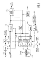
- FIG. 1 shows a television receiver receiving for processing both analog NTSC television signals and internet information . The system shown in FIG. 1 has a
first input 1100 for receiving television signal RF_IN at RF frequencies and asecond input 1102 for receiving baseband television signal VIDEO IN. Signal RF_IN may be supplied from a source such as an antenna or cable system while signal VIDEO IN may be supplied, for example, by a video cassette recorder (VCR) or a gaming device (both not shown in FIG. 1). Tuner 1105 and IFprocessor 1130 operate in a conventional manner for tuning and demodulating a particular television signal that is included in signal RF_IN. IFprocessor 1130 produces baseband video signal VIDEO representing the video program portion of the tuned television signal.IF processor 1130 also produces a baseband audio signal that is coupled to an audio processing section (not shown in FIG. 1) for further audio processing. Although FIG. 1 showsinput 1102 as a baseband signal, the television receiver could include a second tuner and IF processor similar tounits - The system shown in FIG. 1 also includes a main microprocessor (µP) 1110 for controlling components of the television receiver such as
tuner 1105, picture-in-picture processing unit 1140,video signal processor 1155, and StarSight®data processing module 1160. As used herein, the term "microprocessor" represents various devices including, but not limited to, microprocessors, microcomputers, microcontrollers, control processors, and controllers.Microprocessor 1110 controls the system by sending and receiving both commands and data via serial data bus I2C BUS which utilizes the well-known I2C serial data bus protocol. More specifically, central processing unit (CPU) 1112 withinµP 1110 executes control programs contained within memory, such as EEPROM 1127 shown in FIG. 1, in response to commands provided by a user, e.g., viaIR remote control 1125 andIR receiver 1122. For example, activation of a "CHANNEL UP" feature onremote control 1125 causesCPU 1112 to send a "change channel" command along with channel data to tuner 1105 via I2C BUS. As a result,tuner 1105 tunes the next channel in the channel scan list. The control program stored in EEPROM 1127 also includes software for implementing the operations shown in FIG. 2. -
Main microprocessor 1110 also controls the operation of acommunications interface unit 1113 for providing the capability to download and upload information from the internet.Communication interface unit 1113 includes, for example, a modem for connecting to an internet service provider, e.g., via a telephone line or via a cable television line. The communication capability allows the system shown in Figure 1 to provide email capability and internet related features such as web browsing in addition to receiving television programming. -
CPU 1112 controls functions included withinµP 1110 viabus 1119 withinµP 1110. In particular,CPU 1112 controlsauxiliary data processor 1115 and on-screen display (OSD) processor 1117. One function of theauxiliary data processor 1115 is to extract auxiliary data such as StarSight® data from video signal PIPV. - StarSight® system is an Electronic Program Guide (EPG) provided by StacSight Telecast, Inc. An EPG is an interactive, on-screen equivalent to TV listings found in local newspapers or other print media. The information contained in an EPG includes programming characteristics such as channel number, program title, start time, end time, elapsed time, time remaining, rating (if available), topic, theme, and a brief description of the program's content. Aspects of the StarSight® system are described in US Pat. Nos. 5,353,121, 5,479,268, and 5,47,9,266 issued to Young et al. and assigned to StarSight Telecast, Inc.
- StarSight® data is typically received only on a particular television channel and the television receiver must tune that channel to extract StarSight® data. To prevent StarSight® data extraction from interfering with normal use of the television receiver,
CPU 1112 initiates StarSight® data extractioorby tuning the particular channel only during a time period when the television receiver is usually not in use (e.g., 2:00 AM). At that time,CPU 1112 configuresdecoder 1115 such that auxiliary data is extracted from horizontal line intervals such as line 16 that are used for StarSight® data.CPU 1112 controls the transfer of extracted StarSight® data fromdecoder 1115 via I2C BUS toStarSight® module 1160. A processor internal to the module formats and stores the data in memory within the module. In response to the StarSight® EPG display being activated (e.g., a user activating a particular key on remote control 1125),CPU 1112 transfers formatted StaiSight® EPG display data fromStarSight® module 1160 via I2C BUS to OSD processor 1117. - OSD processor 1117 operates in a conventional manner to produce R, G, and B video signals OSD_RGB that, when coupled to a display device, will produce a displayed image representing on-screen display information such as graphics and/or text comprising an EPG or graphics and/or text downloaded from internet as described below. OSD processor 1117 also produces control signal FSW which is intended to control a fast switch for inserting signals OSD_RGB into the system's video output signal at times when an on-screen display is to be displayed. For example, when a user enables an EPG, e.g., by activating a particular switch on
remote control 1125,CPU 1112 enablesprocessors 1115 and 1117 so thatprocessor 1115 first requests and receives EPG data fromStarSight® module 1160 via I2C BUS. Processor 1117 then produces signals OSD_RGB representing the closed caption data. Processor 1117 also produces signal FSW indicating when the EPG is to be displayed. - Another function of the OSD processor 1117is to generate computer text or graphics obtained from the internet, in cooperation with the
communication interface unit 1113 and theAuxiliary Data Processor 1115. Thecommunication interface unit 1113 demodulates the analog information into digital format and passes it to theAuxiliary Data Processor 1115 for further processing. The OSD processor then formats this digital information into RGB signals suitable for used by theVideo Signal Processor 1155. As described above, the OSD produces control signal FSW which is intended to control a fast switch for inserting signals OSD_RGB into the system's video output signal at times When internet graphics and text is to be displayed. - Video signal processor (VSP) 1155 performs conventional video signal processing functions, such as luma and chroma processing and contrast and brightness adjustment. Output image signals produced by
VSP 1155 are suitable for coupling to a display device, e.g., a kinescope or LCD device (not shown in FIG. 1), for producing a displayed image. VSP 115 5 also includes a fast switch for coupling signals produced by OSD processor 1117 to the output video signal path at times when graphics and/or text is to be included in the displayed image. The fast switch is controlled by control signal FSW which is generated by OSD processor 1117 inmain microprocessor 1110 at times when text and/or graphics are to be displayed. - The input signal for
VSP 1155 is signal PIPV that is output by picture-in-picture (PIP)processor 1140. When a user activates PIP mode, signal PIPV represents a large picture (large pix) into which a small picture (small pix) is inset. When PIP mode is inactive, signal PIPV represents just the large pix, i.e., no small pix signal is included in signal PIPV.PIP processor 1140 provides the described functionality in a conventional manner using features included inunit 1140 such as a video switch, analog-to-digital converter (ADC), RAM, and digital to analog converter (DAC). - As described above, and as shown in FIG. 5A, the
subpicture 501 of thePIP image 500 of the television may be used to present text and/or graphics information from the internet, or text and/or graphics information from the EPG while themain picture 502 is showing a TV broadcast channel. This is accomplished by feeding the processed digital signals from the OSD processor 1117 directly to one of the inputs of the PIP processor. As it is well known in the art, the video switch typically contained in thePIP processor 1140 receives all the signal inputs (e.g., VIDEO, VIDEO IN, and signal from OSD as shown in FIG. 1). Then the PIP processor under the control of themain microprocessor 1110, selects and switches the appropriate signals to be displayed during the appropriate main and subpicture scanning intervals. Conventional subsampling techniques are used to form the subpicture. - For an EPG display, the display data included in the EPG display is produced by OSD processor 1117 and included in the output signal by
VSP 1155 in response to fast switch signal FSW. Whencontroller 1110 detects activation of the EPG display, e.g., when a user presses the appropriate key onremote control 1125,controller 1110 causes OSD processor 1117 to produce the EPG display using information such as program guide data fromStarSight® module 1160.Controller 1110 causesVSP 1155 to combine the EPG display data from OSD processor 1117 and the video image signal in response to signal FSW to produce a display including EPG. The EPG can occupy all or only a portion of the display area. - When the EPG display is active,
controller 1110 executes another control program stored inEEPROM 1127. The control program monitors the location of a position indicator, such as a cursor and/or highlighting, in the EPG display. A user controls the location of the position indicator using direction and selection keys ofremote control 1125. Alternatively, the system could include a mouse device.Controller 1110 detects activation of a selection device, such as clicking a mouse button, and evaluates current cursor location information in conjunction with EPG data being displayed to determine the function desired, e.g., tuning a particular program.Controller 1110 subsequently activates the control action associated with the selected feature. - Examples of suitable components for implementing the exemplary embodiment include an ST9296 microprocessor produced by SGS-Thomson Microelectronics for providing the features associated with
µP 1110; an M65616 picture-in-picture processor produced by Mitsubishi for providing the described basic PIP functionality associated withPIP processor 1140; and an LA7612 video signal processor produced by Sanyo for providing the functions ofVSP 1155. - In accordance with the present invention, the
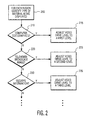
main microprocessor 1110, under the supervision of the control programs contained withinmemory EEPROM 1127, will direct thevideo signal processor 1155 to provide the proper drive levels to the display, via the bus I2C BUS. As shown in the processing steps of Fig. 2, as the video signal processor is providing drive current for picture rasters, themain microprocessor 1110 will first determine which region the rasters belong to. A region, for example, may be a main or subpicture in the PIP mode. As discussed above, the main picture may be displaying the TV images and the subpicture of the PIP may be showing internet text and/or graphics or an EPG, or vise versa. - The
microprocessor 1110 will then determine whether the material being displayed is: 1) a computer text/graphics image such as information obtained from the internet, 2) a television broadcast image, or 3) an OSD information such as an EPG, as shown insteps main microprocessor 1110 makes this determination by coordinating and monitoring the operations of the OSD processor 1117,CPU 1112, and theAuxiliary Data Processor 1115. Themain microprocessor 1110 will then provide a control signal to the video signal processor so that thevideo signal processor 1155 can provide the desired video drive level to the display for the particular material being displayed during the associated scanning interval. - In addition, Figure 1 includes a
control switch 1118 coupled tomicroprocessor 1110. Thecontrol switch 1118 can be used to select the mode of operation for the television set. For example, when a user selects the "auto mode", the television operates automatically to adjust the image characteristics of the drive signals for each display region as described above. When the switch is in the "manual mode 1" position, the user may only adjust the image characteristic of the entire screen. When the switch is in "manual mode 2" position, the television may provide a prompt for the user to select the desired image characteristic for each region. This aspect of the invention will be further described in regard to a PC implementation shown in FIGS. 3 and 4. - Fig. 3 shows another example of an electronic device implementing a video drive control system in accordance with the present invention. The example is a computer system having a television tuner card installed in one of its computer card slots.
- The
computer system 10 is under the control of aCPU processor 110. The computer includes adisplay processor 130 for controlling akine drive 135 of an associateddisplay monitor 136. Thedisplay processor 130, under the control of theCPU processor 110 via a computer operating system to be discussed later, provides for each pixel a desired video drive level. - The
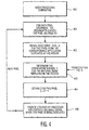
computer system 10 includes atelevision tuner card 100 for receiving television signals to be displayed. It is known, for example, to be able to concurrently display a television image in one of the windows under, for example, a windows based operating system, while performing other computing applications in other windows, as shown in Fig. 5B. An example of an expansion card having a TV tuner that can be used with an IBM-compatible PC is "All-In-Wonder"™ card made by ATI Technologies Inc., of Canada. - FIG. 4 shows in a flowchart form a feature of the system shown in FIG. 3. In Fig. 4, the operating system of the PC has a
video processing subroutine 400 to provide the proper display drive control for each pixel of the display according to the principles of the present invention. - The operating system which contains the
video processing subroutine 400, provides to thedisplay processor 130 intensity information such as contrast and brightness characteristics about each pixel, as each pixel is being displayed on the display monitor 136 in the display scanning process. This intensity information typically corresponds to R, G, and B drive levels for each pixel on the display. - The operating system knows the location and the boundary of the windows or regions since the operating system is responsible for coordinating the resources among the different applications being displayed. Therefore, as each pixel is being displayed in the CRT scanning process, the operating system first determines which region or application this pixel belongs to, as shown in
Step 401. - Once this is determined, the operating system then obtains a normal drive level (X) for this pixel from the corresponding application program as shown in
step 402. The drive levels (X) for a pixel in an application are normally represented internally as numbers, which can be represented as fractions of the maximum drive level. These might be thought of, for example as 0, 0.25, 0.50, 0.75, and 1.00, although many more levels are usually incorporated. - To exert the required control of regions in accordance with the type of the material or information being displayed, these drive numbers, received from the application being displayed in a window, would be multiplied by a second number Y as shown in
step 403. The second number Y is an attenuation number associated with the window currently being scanned. For example, the high-drive picture regions corresponding to real-world photographic style or television broadcast images might have an assigned attenuation number Y of 1.0 (no attenuation), but the computer-related text/graphics regions might have an assigned attenuation number Y of 0.25 (4 to 1 attenuation). - Each pixel appearing in a window, which is of a certain type, is thereafter assigned an associated, final, attenuation level or a drive signal level Z. This level, Z, is derived from, for example, the multiplication of the normal application video level X for each pixel in the region by the assigned attenuation number Y for that region or window, resulting in independent control of each region's video level appropriate for its type of material being presented, as shown in
step 404. This number Z is then provided to thedisplay processor 130 which will drive thekine drive 135 and the associateddisplay 136 at the appropriate level for each pixel. This process is then repeated for each pixel of the displayed image until thesystem 10 is turned off. - In accordance with another aspect of the present invention, the system shown in FIG. 3 may provide a user interface feature to provide user adjustment of the final drive level for each window or application on the screen. This function is similar to that described above when
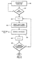
switch 1118 of the television shown in FIG. 1 is in "manual mode 2" position. - FIG. 6,
steps 600 to 606, show in flow chart form, a user interface feature according to the present invention. The feature illustrated in FIG. 6 may be implemented as a subroutine of the operating system that is exercised byCPU 110 of the system shown in FIG. 3. The user can, for example enter a key on a keyboard (not shown) of thecomputer system 10 to invoke this feature, as shown inStep 600. Thereafter, thecomputer system 100 will prompt the user via thedisplay screen 136 to enter a new, overriding attenuation number Y for each region shown on the screen, as shown inStep 603. Once a number is entered by the user, the computer system overrides the old attenuation number Y previously derived by the CPU processor with this new number Y, thereby causing the final drive level Z for this particular window to be adjusted according to the user's taste. Thus the user is able to manually adjust the drive level for each of the regions currently being displayed on the computer screen. - The above described concepts according to the present invention can be extended, if desired, to several levels of control for numerous types of presentation materials, to optimize the drive level of each region, according to the content.
Claims (18)
- A video processing system for providing an image having more than one region (501, 502, 510, 512, 513, 514) comprising:means (1119) for obtaining for each region of the displayed image, data indicating the type of information to be displayed in each region before processing the information in each region;means for deriving (1110) a display level for each region of the image according to the data obtained indicating the type of information being displayed in each region; andmeans for adjusting (1155) the display level for each region as the image is displayed.
- The system of claim 1 wherein the data indicate that the information corresponds to a television program.
- The system of claim 1 wherein the data indicate that the information corresponds to computer generated text and/or graphics.
- The system of claim 1, 2 or 3, wherein the display level corresponds to a contrast level.
- The system of claim 1, 2 or 3, wherein the display level corresponds to a brightness level.
- The system of claim 1, 2 or 3, wherein the display level is derived by obtaining a normal drive level (X) for each pixel and an attenuation number (Y) for each region of the image being displayed.
- The system of claim 6, wherein the display level for each pixel of the displayed image is derived by multiplication of the normal drive level (X) and the attenuation number (Y) for the pixel.
- The system of claim 1 wherein the data obtained is provided by a program associated a particular region.
- The system of claim 1 wherein the data obtained is specified by a user.
- A method for providing a displayed image having more than one display region comprising the steps of:obtaining (200) for each region of the displayed image, data indicating the type of information to be displayed in each region before processing the information in each region;deriving (210, 220, 230) a display level for each region of the image according to the data previously obtained indicating the type of information being displayed in each region; andadjusting (215, 225, 235) the display level for each region as the image is displayed.
- The method of claim 10 wherein the data indicate that the information corresponds to a television program.
- The method of claim 10 wherein the data indicate that the information corresponds to computer generated text and/or graphics.
- The method of claim 10, 11, or 12, wherein the display level corresponds to a contrast level.
- The method of claim 10, 11, or 12, wherein the display level corresponds to a brightness level.
- The method of claim 11 wherein the step of deriving the display level further comprises the step of obtaining a normal drive level (X) for each pixel and an attenuation number (Y) for each region of the image being displayed.
- The method of claim 15, wherein the display level for each pixel is derived by multiplication of the normal drive level (X) and the attenuation number (Y) for the pixel.
- The method of claim 11 wherein the data obtained is provided by a program associated a particular region.
- The method of claim 11 wherein the data obtained is specified by a user.
Applications Claiming Priority (3)
| Application Number | Priority Date | Filing Date | Title |
|---|---|---|---|
| US4409797P | 1997-04-23 | 1997-04-23 | |
| US44097P | 1997-04-23 | ||
| PCT/US1997/024210 WO1998048571A1 (en) | 1997-04-23 | 1997-12-29 | Control of video level by region and content of information displayed |
Publications (2)
| Publication Number | Publication Date |
|---|---|
| EP0978197A1 EP0978197A1 (en) | 2000-02-09 |
| EP0978197B1 true EP0978197B1 (en) | 2004-10-06 |
Family
ID=21930518
Family Applications (1)
| Application Number | Title | Priority Date | Filing Date |
|---|---|---|---|
| EP97954312A Expired - Lifetime EP0978197B1 (en) | 1997-04-23 | 1997-12-29 | Control of video level by region and content of information displayed |
Country Status (7)
| Country | Link |
|---|---|
| EP (1) | EP0978197B1 (en) |
| JP (1) | JP4732553B2 (en) |
| KR (1) | KR100526740B1 (en) |
| CN (1) | CN1143528C (en) |
| AU (1) | AU5811998A (en) |
| DE (1) | DE69731120T2 (en) |
| WO (1) | WO1998048571A1 (en) |
Families Citing this family (46)
| Publication number | Priority date | Publication date | Assignee | Title |
|---|---|---|---|---|
| KR100610033B1 (en) * | 1997-12-31 | 2006-08-09 | 코닌클리케 필립스 일렉트로닉스 엔.브이. | Apparatus and method for dynamically controlling brightness of objects on a display monitor |
| JP3595745B2 (en) * | 1999-01-29 | 2004-12-02 | キヤノン株式会社 | Image processing device |
| US6556253B1 (en) * | 1999-10-26 | 2003-04-29 | Thomson Licensing S.A. | Multi-window picture adjustment arrangement for a video display |
| KR100322755B1 (en) * | 2000-02-14 | 2002-02-07 | 윤종용 | Video apparatus with variable osd graphic data |
| KR100343385B1 (en) * | 2000-04-24 | 2002-07-15 | 윤종용 | Osd(on screen display) cursor display method and osd image display apparatus |
| FI115186B (en) * | 2000-12-18 | 2005-03-15 | Alma Media Oyj | Television broadcasting system and method of broadcasting television commercials |
| US7191402B2 (en) * | 2001-05-10 | 2007-03-13 | Samsung Electronics Co., Ltd. | Method and apparatus for adjusting contrast and sharpness for regions in a display device |
| US20030007001A1 (en) * | 2001-06-07 | 2003-01-09 | Philips Electronics North America Corporation | Automatic setting of video and audio settings for media output devices |
| JP3658362B2 (en) * | 2001-11-08 | 2005-06-08 | キヤノン株式会社 | Video display device and control method thereof |
| DE10210485B4 (en) * | 2002-03-11 | 2006-01-12 | Loewe Opta Gmbh | TV receiver with online module |
| JP3783645B2 (en) * | 2002-04-05 | 2006-06-07 | 株式会社日立製作所 | Contrast adjustment method, contrast adjustment circuit, and video display device using the same |
| US7623115B2 (en) * | 2002-07-27 | 2009-11-24 | Sony Computer Entertainment Inc. | Method and apparatus for light input device |
| US7646372B2 (en) | 2003-09-15 | 2010-01-12 | Sony Computer Entertainment Inc. | Methods and systems for enabling direction detection when interfacing with a computer program |
| US8797260B2 (en) | 2002-07-27 | 2014-08-05 | Sony Computer Entertainment Inc. | Inertially trackable hand-held controller |
| US8019121B2 (en) | 2002-07-27 | 2011-09-13 | Sony Computer Entertainment Inc. | Method and system for processing intensity from input devices for interfacing with a computer program |
| US9393487B2 (en) | 2002-07-27 | 2016-07-19 | Sony Interactive Entertainment Inc. | Method for mapping movements of a hand-held controller to game commands |
| US9474968B2 (en) | 2002-07-27 | 2016-10-25 | Sony Interactive Entertainment America Llc | Method and system for applying gearing effects to visual tracking |
| US8570378B2 (en) | 2002-07-27 | 2013-10-29 | Sony Computer Entertainment Inc. | Method and apparatus for tracking three-dimensional movements of an object using a depth sensing camera |
| US8313380B2 (en) | 2002-07-27 | 2012-11-20 | Sony Computer Entertainment America Llc | Scheme for translating movements of a hand-held controller into inputs for a system |
| US7760248B2 (en) | 2002-07-27 | 2010-07-20 | Sony Computer Entertainment Inc. | Selective sound source listening in conjunction with computer interactive processing |
| US9682319B2 (en) | 2002-07-31 | 2017-06-20 | Sony Interactive Entertainment Inc. | Combiner method for altering game gearing |
| US9177387B2 (en) | 2003-02-11 | 2015-11-03 | Sony Computer Entertainment Inc. | Method and apparatus for real time motion capture |
| US8072470B2 (en) | 2003-05-29 | 2011-12-06 | Sony Computer Entertainment Inc. | System and method for providing a real-time three-dimensional interactive environment |
| US9573056B2 (en) | 2005-10-26 | 2017-02-21 | Sony Interactive Entertainment Inc. | Expandable control device via hardware attachment |
| US10279254B2 (en) | 2005-10-26 | 2019-05-07 | Sony Interactive Entertainment Inc. | Controller having visually trackable object for interfacing with a gaming system |
| US20050063418A1 (en) * | 2003-09-23 | 2005-03-24 | Case Michael L. | Tuner module utilizing device-specific controller |
| JP4175234B2 (en) * | 2003-10-07 | 2008-11-05 | セイコーエプソン株式会社 | Display control apparatus, portable information terminal, and display control method |
| US7663689B2 (en) | 2004-01-16 | 2010-02-16 | Sony Computer Entertainment Inc. | Method and apparatus for optimizing capture device settings through depth information |
| US8547401B2 (en) | 2004-08-19 | 2013-10-01 | Sony Computer Entertainment Inc. | Portable augmented reality device and method |
| JP3863904B1 (en) * | 2005-03-30 | 2006-12-27 | シャープ株式会社 | Liquid crystal display |
| ATE516086T1 (en) | 2005-05-23 | 2011-07-15 | Biosonic Australia Pty Ltd | DEVICE FOR ATOMIZING AND LIQUID FILTRATION |
| CA2616095A1 (en) * | 2005-08-05 | 2007-02-15 | Samsung Electronics Co., Ltd. | Apparatus for providing multiple screens and method of dynamically configuring multiple screens |
| US8046706B2 (en) | 2005-08-05 | 2011-10-25 | Samsung Electronics Co., Ltd. | Apparatus for providing multiple screens and method of dynamically configuring multiple screens |
| CA2615762A1 (en) * | 2005-08-05 | 2007-02-15 | Samsung Electronics Co., Ltd. | Apparatus for providing multiple screens and method of dynamically configuring multiple screens |
| JP3953506B2 (en) * | 2005-10-18 | 2007-08-08 | シャープ株式会社 | Liquid crystal display |
| USRE48417E1 (en) | 2006-09-28 | 2021-02-02 | Sony Interactive Entertainment Inc. | Object direction using video input combined with tilt angle information |
| JP5013832B2 (en) * | 2006-12-05 | 2012-08-29 | キヤノン株式会社 | Image control apparatus and method |
| JP4686503B2 (en) * | 2007-05-31 | 2011-05-25 | 株式会社日立製作所 | Image display device |
| KR101487434B1 (en) | 2007-11-14 | 2015-01-29 | 삼성전자 주식회사 | Diaplay apparatus and control method of the same |
| US8542907B2 (en) | 2007-12-17 | 2013-09-24 | Sony Computer Entertainment America Llc | Dynamic three-dimensional object mapping for user-defined control device |
| EP2257911B1 (en) | 2008-02-27 | 2018-10-10 | Sony Computer Entertainment America LLC | Methods for capturing depth data of a scene and applying computer actions |
| JP5039829B2 (en) * | 2010-12-22 | 2012-10-03 | 株式会社日立製作所 | Image display device |
| CN103135738A (en) * | 2011-11-28 | 2013-06-05 | 联想(北京)有限公司 | Display method and electronic equipment |
| CN102592568B (en) * | 2011-12-29 | 2014-11-26 | 中航(苏州)雷达与电子技术有限公司 | Multi-window contrast control method for touch screen display |
| CN103414950B (en) * | 2013-08-16 | 2016-09-14 | 天脉聚源(北京)传媒科技有限公司 | A kind of method for showing interface, device, Set Top Box and server |
| GB2527738B (en) * | 2014-05-12 | 2020-08-12 | Apical Ltd | Method and apparatus for controlling a display |
Family Cites Families (4)
| Publication number | Priority date | Publication date | Assignee | Title |
|---|---|---|---|---|
| US5204748A (en) * | 1991-12-11 | 1993-04-20 | Thomson Consumer Electronics, Inc. | Beam current limiting arrangement for a television system with picture-in-picture provisions |
| JPH05316446A (en) * | 1992-05-08 | 1993-11-26 | Matsushita Electric Ind Co Ltd | Multigradation correction device |
| JPH07264503A (en) * | 1994-03-23 | 1995-10-13 | Toshiba Corp | Television receiver |
| CN1135140A (en) * | 1995-02-27 | 1996-11-06 | 松下电器产业株式会社 | Compensation voltage generating apparatus for multipicture display and video display apparatus using same |
-
1997
- 1997-12-29 DE DE69731120T patent/DE69731120T2/en not_active Expired - Lifetime
- 1997-12-29 WO PCT/US1997/024210 patent/WO1998048571A1/en active IP Right Grant
- 1997-12-29 KR KR10-1999-7009525A patent/KR100526740B1/en active IP Right Grant
- 1997-12-29 EP EP97954312A patent/EP0978197B1/en not_active Expired - Lifetime
- 1997-12-29 CN CNB971821313A patent/CN1143528C/en not_active Expired - Lifetime
- 1997-12-29 AU AU58119/98A patent/AU5811998A/en not_active Abandoned
- 1997-12-29 JP JP54567798A patent/JP4732553B2/en not_active Expired - Lifetime
Also Published As
| Publication number | Publication date |
|---|---|
| JP2001523409A (en) | 2001-11-20 |
| EP0978197A1 (en) | 2000-02-09 |
| KR100526740B1 (en) | 2005-11-08 |
| KR20010006435A (en) | 2001-01-26 |
| CN1143528C (en) | 2004-03-24 |
| WO1998048571A1 (en) | 1998-10-29 |
| DE69731120D1 (en) | 2004-11-11 |
| CN1253693A (en) | 2000-05-17 |
| JP4732553B2 (en) | 2011-07-27 |
| AU5811998A (en) | 1998-11-13 |
| DE69731120T2 (en) | 2005-02-24 |
Similar Documents
| Publication | Publication Date | Title |
|---|---|---|
| EP0978197B1 (en) | Control of video level by region and content of information displayed | |
| US6809776B1 (en) | Control of video level by region and content of information displayed | |
| US5528304A (en) | Picture-in-picture feedback for channel related features | |
| EP1586026B1 (en) | System and method for advertising a currently airing program through the use of an electronic program guide interface | |
| US7643095B2 (en) | Image display device, image display method, and television receiver | |
| JP4353440B2 (en) | Video signal processing apparatus and method | |
| EP1095510B1 (en) | Web browser system for displaying recently viewed television channels | |
| US7864249B2 (en) | Method and apparatus displaying double screen | |
| US7009659B2 (en) | System and method for establishing TV settings | |
| US5416534A (en) | Monitor apparatus including video processing circuit for selecting image quality modes | |
| EP0968604A1 (en) | Picture in an electronic program guide for a video processing system | |
| JP3686523B2 (en) | Receiver | |
| JP2000115664A (en) | Information display system | |
| AU720976B2 (en) | Television receiver | |
| EP1672924B1 (en) | Display Apparatus and Method | |
| JP2000105650A (en) | Device and method for displaying information | |
| KR100223781B1 (en) | Method of controlling the internet screen searching of an internet television | |
| WO2002017623A1 (en) | An internet access device | |
| EP1933559A2 (en) | Display apparatus and control method thereof | |
| KR20080048126A (en) | Method and apparatus for the teletext controlling of image display device |
Legal Events
| Date | Code | Title | Description |
|---|---|---|---|
| PUAI | Public reference made under article 153(3) epc to a published international application that has entered the european phase |
Free format text: ORIGINAL CODE: 0009012 |
|
| 17P | Request for examination filed |
Effective date: 19991009 |
|
| AK | Designated contracting states |
Kind code of ref document: A1 Designated state(s): DE FR GB IT |
|
| 17Q | First examination report despatched |
Effective date: 20020911 |
|
| GRAP | Despatch of communication of intention to grant a patent |
Free format text: ORIGINAL CODE: EPIDOSNIGR1 |
|
| GRAS | Grant fee paid |
Free format text: ORIGINAL CODE: EPIDOSNIGR3 |
|
| GRAA | (expected) grant |
Free format text: ORIGINAL CODE: 0009210 |
|
| AK | Designated contracting states |
Kind code of ref document: B1 Designated state(s): DE FR GB IT |
|
| REG | Reference to a national code |
Ref country code: GB Ref legal event code: FG4D |
|
| REG | Reference to a national code |
Ref country code: GB Ref legal event code: 746 Effective date: 20041014 |
|
| REF | Corresponds to: |
Ref document number: 69731120 Country of ref document: DE Date of ref document: 20041111 Kind code of ref document: P |
|
| PLBE | No opposition filed within time limit |
Free format text: ORIGINAL CODE: 0009261 |
|
| STAA | Information on the status of an ep patent application or granted ep patent |
Free format text: STATUS: NO OPPOSITION FILED WITHIN TIME LIMIT |
|
| ET | Fr: translation filed | ||
| 26N | No opposition filed |
Effective date: 20050707 |
|
| REG | Reference to a national code |
Ref country code: FR Ref legal event code: PLFP Year of fee payment: 19 |
|
| REG | Reference to a national code |
Ref country code: FR Ref legal event code: PLFP Year of fee payment: 20 |
|
| PGFP | Annual fee paid to national office [announced via postgrant information from national office to epo] |
Ref country code: FR Payment date: 20161222 Year of fee payment: 20 Ref country code: IT Payment date: 20161221 Year of fee payment: 20 |
|
| PGFP | Annual fee paid to national office [announced via postgrant information from national office to epo] |
Ref country code: DE Payment date: 20161221 Year of fee payment: 20 |
|
| PGFP | Annual fee paid to national office [announced via postgrant information from national office to epo] |
Ref country code: GB Payment date: 20170130 Year of fee payment: 20 |
|
| REG | Reference to a national code |
Ref country code: DE Ref legal event code: R082 Ref document number: 69731120 Country of ref document: DE Representative=s name: HOFSTETTER, SCHURACK & PARTNER PATENT- UND REC, DE |
|
| REG | Reference to a national code |
Ref country code: DE Ref legal event code: R071 Ref document number: 69731120 Country of ref document: DE |
|
| REG | Reference to a national code |
Ref country code: GB Ref legal event code: PE20 Expiry date: 20171228 |
|
| PG25 | Lapsed in a contracting state [announced via postgrant information from national office to epo] |
Ref country code: GB Free format text: LAPSE BECAUSE OF EXPIRATION OF PROTECTION Effective date: 20171228 |