EP0977435A2 - Method and apparatus for conveying picture information - Google Patents
Method and apparatus for conveying picture information Download PDFInfo
- Publication number
- EP0977435A2 EP0977435A2 EP99202249A EP99202249A EP0977435A2 EP 0977435 A2 EP0977435 A2 EP 0977435A2 EP 99202249 A EP99202249 A EP 99202249A EP 99202249 A EP99202249 A EP 99202249A EP 0977435 A2 EP0977435 A2 EP 0977435A2
- Authority
- EP
- European Patent Office
- Prior art keywords
- matrix
- pixels
- line length
- store
- conform
- Prior art date
- Legal status (The legal status is an assumption and is not a legal conclusion. Google has not performed a legal analysis and makes no representation as to the accuracy of the status listed.)
- Granted
Links
Images

Classifications
-
- H—ELECTRICITY
- H04—ELECTRIC COMMUNICATION TECHNIQUE
- H04N—PICTORIAL COMMUNICATION, e.g. TELEVISION
- H04N7/00—Television systems
- H04N7/01—Conversion of standards, e.g. involving analogue television standards or digital television standards processed at pixel level
- H04N7/0125—Conversion of standards, e.g. involving analogue television standards or digital television standards processed at pixel level one of the standards being a high definition standard
Definitions
- This invention relates to the conveyance of picture information, and particularly to the conveyance of non-standard format picture information.
- the number of horizontal scanning lines, or alternatively the number of pixels within a matrix, used to display picture information is known as the "format" of picture information.
- the format of any particular picture display is of fundamental importance to defined standards in e.g. the broadcast industry. Typical examples of such formats are those of standard digital television (SDTV), which includes the European broadcast standard of 625 lines at a frequency of 50Hz, and the American standard of 60Hz frequency and a pixel matrix of at least 720 ⁇ 483 (columns ⁇ rows) in the visible area. European SDTV pictures have a format of 704 x 480.
- High Definition Television (HDTV) has a much higher resolution than SDTV, with some of the more common pixel matrices being 1920 ⁇ 1080 (although the useable, available matrix is 1920 ⁇ 1088) and 1280 ⁇ 720.
- Our pending application GB 9807206.9 describes, amongst other aspects, a method suitable for the broadcasting of HDTV programming (including picture information) by modifying an existing broadcasting system.
- This method includes the steps of splitting the television image into a spatial array of elements and encoding each of the elements in a separate encoder.
- the exemplified embodiment describes six elements (in a 3 ⁇ 2 matrix) each having a format of 640 ⁇ 544 pixels. This element format is not a standard digital television format.
- one object of the present invention is to overcome the problems associated with the prior art.
- a method of changing an input picture signal representing lines of pixels arranged to conform to a first matrix of a first line length to an output picture signal representing lines of pixels arranged to conform to a second matrix of a second line length comprising the steps of: entering into a store the pixels of the input signal sequentially in the order of the first matrix; and retrieving the pixels from the store in the same sequential order as entry but in lines which have a different number of pixels per line and wherein the pixels spill over from one line into the next line to conform to the line length of the second matrix.
- apparatus for changing an input picture signal representing lines of pixels arranged to conform to a first matrix of a first line length to an output picture signal representing lines of pixels arranged to conform to a second matrix of a second line length
- the apparatus comprising: a store to store the pixels of the input signal sequentially in the order of the first matrix; and a means to output the pixels from the store in the same sequential order as entry but in lines which have a different number of pixels per line and wherein the pixels spill over from one line to the next line to conform to the line length of the second matrix.
- the invention allows cost-effective standard interface components to be used to convey the pixels of the picture signal in the standard format.
- use of standard interface components facilitates interoperability with other existing standard components such as switches and routers within systems.
- the pixels may spill from one line to the next line in a variety of predetermined ways. Typical examples are those of "wrapping” and “serpentine” spilling. Where wrapping occurs each successive line is filled from left to right, whilst serpentine spilling allows alternate filling from left to right to be followed by filling from right to left, and so on.
- each of the method and apparatus may be duplicated in reverse so as to recover the picture information in the first format.
- the picture information may be changed to conform to yet a third format.
- the store is additionally provided with a means for instructing the store to store active picture (image) information only.
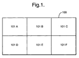
- Figure 1 shows an a representation of a HDTV image 100 divided into a number of elements 101, A to F.
- the format of image 100 is 1920 ⁇ 1080 pixels, whilst that of each of elements 101 A-F is 640 ⁇ 544.
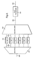
- FIG. 2 there is shown a diagram illustrating an overview of a HDTV system.
- a HDTV signal 200 is input to a signal splitter 201.
- the signal splitter 201 divides the image 100 into elements 101 and creates a separate digital bitstream 202 for each element.
- the HDTV image is divided up into six standard television pictures.
- Each data stream 202 is encoded by a separate standard television encoder 203 to produce a MPEG specific digital bitstream having a main profile at high level (MP@HL).
- Element A of Figure 1 is encoded by encoder A of Figure 2
- element B of Figure 1 is encoded by encoder B of Figure 2 and so on.
- the six individual standard television digital bitstreams 204 are then input to a standard multiplexer 205, which may be a statistical multiplexer.
- the multiplexer 205 multiplexes together the six individual bitstreams to form a single multiplexed bitstream 206.
- the multiplexed bitstream 206 is a standard multiplexed bitstream containing each of the bitstreams from encoders 203 A-F independent from one another.
- post processor 207 the multiplexed bitstream 206 becomes a HDTV compliant multiplexed bitstream 208.
- the splitter 201 is shown coupled to one only of encoders 203.
- the splitter 201 is coupled to each of the other encoders 203 in a manner generally indicated in Figure 2 but for clarity, Figure 3 shows only one of the encoders 203.
- the encoder 203 shown in Figure 3 encodes a specific one of the elements 101 of the image 100 but the pixels of that element are reformatted, according to the present invention, before being supplied to the corresponding encoder.
- the signal 301 supplied by the splitter 201 represents the picture information of the respective image element 101 arranged in a pixel matrix which has a format of 640 ⁇ 544 matrix points and a nominal frame rate of 30Hz (i.e. 30 frames per second).
- Serially connected FIFO buffers 302 and 307 link the splitter 201 to the encoder 203.
- An interface 306 is provided between the FIFO buffers 302 and 307 and control signal inputs 303 and 304 are provided for each of the FIFO buffers 302 and 307.
- the output signal 301 from splitter 201 is provided as an input signal to the FIFO buffer 302.
- control signal 303 instructs the FIFO buffer that the input contains image information that is to be stored.
- Control signal 303 also instructs the FIFO buffer not to store picture information extraneous to the image information, such as blanking information commonly present in television picture information.
- the FIFO buffer 302 is instructed to retrieve the image information to provide as an output signal by control signal 304.
- the output signal from the FIFO buffer 302 conforms to a second matrix having a second line length by synchronous timing of the number of pixels that would be retrieved from the FIFO Buffer 302 within a given particular time period. It will be understood that the time period can vary according to the particular second line length required.
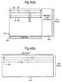
- the format of the image information in the input and output signals can be seen in Figures 4 (a) and (b) respectively.
- Figure 4 (a) shows a schematic view of a field 401 having image information 402 in a matrix having a non-standard format of 640 ⁇ 272 pixels (i.e. a line length of 640 pixels).
- the format of the output signal image information can be seen at Figure 4(b).
- Image information 410 has a different tine length of 720 in a matrix having a format of 720 ⁇ 240 pixels.
- the image information 401 has been reformatted to be accommodated within the format of 410 such that exemplified rows 404 (a) - (d) have been wrapped into the standard format seen in Figure 4(b). It will be understood by those skilled in the art that where information such as blanking is required to supplement image information 410 (whether in the format of Figure 4(b) or a different format), then this can be added during a later stage of processing.
- the output of the FIFO buffer 302 in the format of 410 at a nominal frequency of 60 fields per second is conveyed by standard interface 306.
- This interface is standard component recommended ITU-R.BT 656, which is adapted to convey information having the format and frequency of the output of FIFO buffer 302.
- the second FIFO buffer 307 and its associated control signals 303 and 304 accept the standard format information from interface 306 as an input signal.
- This second buffer 307 acts in the same manner as FIFO buffer 302, i.e. under the control of control signals 303 and 304 to wrap its input signal picture format of the particular standard line length into an output signal picture format having a different non-standard line length.
- the encoder 203 processes the video information to be incorporated to form part of a larger HDTV picture image, the output signal 305 has the same format as the signal 301.
- the input signal to FIFO buffer 307 can be thought of as picture information in a second format, whilst the output signal 305 is picture information in the original, first format.
- the output signal 305 is provided to encoder 203, which in turn provides a standard television encoded output 204.
- each of buffers 302 and 307 can be located within the splitter 201 and the encoder 203 respectively.
- the buffers are then available for combination with other memory operations, thus minimising hardware required within the HDTV system.
Landscapes
- Engineering & Computer Science (AREA)
- Multimedia (AREA)
- Signal Processing (AREA)
- Compression Or Coding Systems Of Tv Signals (AREA)
- Television Systems (AREA)
Abstract
Description
- This invention relates to the conveyance of picture information, and particularly to the conveyance of non-standard format picture information.
- The number of horizontal scanning lines, or alternatively the number of pixels within a matrix, used to display picture information is known as the "format" of picture information. The format of any particular picture display is of fundamental importance to defined standards in e.g. the broadcast industry. Typical examples of such formats are those of standard digital television (SDTV), which includes the European broadcast standard of 625 lines at a frequency of 50Hz, and the American standard of 60Hz frequency and a pixel matrix of at least 720 × 483 (columns × rows) in the visible area. European SDTV pictures have a format of 704 x 480. High Definition Television (HDTV) has a much higher resolution than SDTV, with some of the more common pixel matrices being 1920 × 1080 (although the useable, available matrix is 1920 × 1088) and 1280 × 720.
- Our pending application GB 9807206.9 describes, amongst other aspects, a method suitable for the broadcasting of HDTV programming (including picture information) by modifying an existing broadcasting system. This method includes the steps of splitting the television image into a spatial array of elements and encoding each of the elements in a separate encoder. Although the number of elements will be dependent upon the profile of the original HDTV image, the exemplified embodiment describes six elements (in a 3 × 2 matrix) each having a format of 640 × 544 pixels. This element format is not a standard digital television format.
- It will be understood that during passage of picture information within any system it is important that steps are taken to minimise degradation or distortion of the picture information. This is particularly true of digital television picture information - where significant efforts are devoted to ensuring that artefacts, or other picture characteristics associated with a reduction in the integrity of the picture information, are minimised or eradicated. The presence of characteristics such as artefacts is commonly due to the use of complex processing techniques such as motion prediction. These techniques often rely on a spatial comparison of picture information within successive frames.
- It will also be understood that the components for use within the broadcast industry are designed and manufactured to support the requirement for compliance with standard formats. It is therefore difficult and/or expensive to source components which are non-compliant with such standard formats.
- Accordingly, one object of the present invention is to overcome the problems associated with the prior art.
- According to one aspect of the present invention there is provided a method of changing an input picture signal representing lines of pixels arranged to conform to a first matrix of a first line length to an output picture signal representing lines of pixels arranged to conform to a second matrix of a second line length, the method comprising the steps of: entering into a store the pixels of the input signal sequentially in the order of the first matrix; and retrieving the pixels from the store in the same sequential order as entry but in lines which have a different number of pixels per line and wherein the pixels spill over from one line into the next line to conform to the line length of the second matrix.
- According to a second aspect of the present invention there is provided apparatus for changing an input picture signal representing lines of pixels arranged to conform to a first matrix of a first line length to an output picture signal representing lines of pixels arranged to conform to a second matrix of a second line length, the apparatus comprising: a store to store the pixels of the input signal sequentially in the order of the first matrix; and a means to output the pixels from the store in the same sequential order as entry but in lines which have a different number of pixels per line and wherein the pixels spill over from one line to the next line to conform to the line length of the second matrix.
- Where the first matrix has a non-standard format and the second matrix has a standard format, the invention allows cost-effective standard interface components to be used to convey the pixels of the picture signal in the standard format. In addition, use of standard interface components facilitates interoperability with other existing standard components such as switches and routers within systems.
- It will be apparent to one skilled in the art that the pixels may spill from one line to the next line in a variety of predetermined ways. Typical examples are those of "wrapping" and "serpentine" spilling. Where wrapping occurs each successive line is filled from left to right, whilst serpentine spilling allows alternate filling from left to right to be followed by filling from right to left, and so on.
- Advantageously, each of the method and apparatus may be duplicated in reverse so as to recover the picture information in the first format. Alternatively the picture information may be changed to conform to yet a third format.
- Use of this invention is best suited to conveyance of picture information across standard components where the frequency in the picture information of the first and second format is the same.
- Preferably, where the picture information is video information and is included with other information, the store is additionally provided with a means for instructing the store to store active picture (image) information only.
- The invention will now be described by way of example, with reference to the accompanying drawings, in which:
- Figure 1 is a diagram showing a HDTV image divided into a number of elements;
- Figure 2 is an overview of a transmission head end of a HDTV system;
- Figure 3 is a diagram showing one embodiment of an interface connection suitable for inclusion within the head-end of Figure 1; and
- Figures 4a and 4b are diagrams illustrating a first matrix having a first line length and a second matrix of a second line length respectively.
-
- Figure 1 shows an a representation of a
HDTV image 100 divided into a number ofelements 101, A to F. The format ofimage 100 is 1920 × 1080 pixels, whilst that of each ofelements 101 A-F is 640 × 544. - Turning now to Figure 2, there is shown a diagram illustrating an overview of a HDTV system. A
HDTV signal 200 is input to asignal splitter 201. Thesignal splitter 201 divides theimage 100 intoelements 101 and creates a separatedigital bitstream 202 for each element. In this example, as shown in Figure 1, the HDTV image is divided up into six standard television pictures. Eachdata stream 202 is encoded by a separatestandard television encoder 203 to produce a MPEG specific digital bitstream having a main profile at high level (MP@HL). Element A of Figure 1 is encoded by encoder A of Figure 2, element B of Figure 1 is encoded by encoder B of Figure 2 and so on. - The six individual standard television
digital bitstreams 204 are then input to astandard multiplexer 205, which may be a statistical multiplexer. The multiplexer 205 multiplexes together the six individual bitstreams to form a singlemultiplexed bitstream 206. Themultiplexed bitstream 206 is a standard multiplexed bitstream containing each of the bitstreams fromencoders 203 A-F independent from one another. Following processing bypost processor 207 themultiplexed bitstream 206 becomes a HDTV compliant multiplexedbitstream 208. Reference may be made to our pending application GB 9807206.9 for further information in processing theimage 100 of Figure 1 by means of the apparatus of Figure 2. - In Figure 3, the
splitter 201 is shown coupled to one only ofencoders 203. Thesplitter 201 is coupled to each of theother encoders 203 in a manner generally indicated in Figure 2 but for clarity, Figure 3 shows only one of theencoders 203. Theencoder 203 shown in Figure 3 encodes a specific one of theelements 101 of theimage 100 but the pixels of that element are reformatted, according to the present invention, before being supplied to the corresponding encoder. Thesignal 301 supplied by thesplitter 201 represents the picture information of therespective image element 101 arranged in a pixel matrix which has a format of 640 × 544 matrix points and a nominal frame rate of 30Hz (i.e. 30 frames per second). Serially connectedFIFO buffers splitter 201 to theencoder 203. Aninterface 306 is provided between theFIFO buffers control signal inputs FIFO buffers - The
output signal 301 fromsplitter 201 is provided as an input signal to theFIFO buffer 302. On receipt of this input,control signal 303 instructs the FIFO buffer that the input contains image information that is to be stored.Control signal 303 also instructs the FIFO buffer not to store picture information extraneous to the image information, such as blanking information commonly present in television picture information. TheFIFO buffer 302 is instructed to retrieve the image information to provide as an output signal bycontrol signal 304. The output signal from theFIFO buffer 302 conforms to a second matrix having a second line length by synchronous timing of the number of pixels that would be retrieved from theFIFO Buffer 302 within a given particular time period. It will be understood that the time period can vary according to the particular second line length required. The format of the image information in the input and output signals can be seen in Figures 4 (a) and (b) respectively. - Figure 4 (a) shows a schematic view of a
field 401 havingimage information 402 in a matrix having a non-standard format of 640 × 272 pixels (i.e. a line length of 640 pixels). The format of the output signal image information can be seen at Figure 4(b).Image information 410 has a different tine length of 720 in a matrix having a format of 720 × 240 pixels. Theimage information 401 has been reformatted to be accommodated within the format of 410 such that exemplified rows 404 (a) - (d) have been wrapped into the standard format seen in Figure 4(b). It will be understood by those skilled in the art that where information such as blanking is required to supplement image information 410 (whether in the format of Figure 4(b) or a different format), then this can be added during a later stage of processing. - Returning to Figure 3, the output of the
FIFO buffer 302 in the format of 410 at a nominal frequency of 60 fields per second is conveyed bystandard interface 306. This interface is standard component recommended ITU-R.BT 656, which is adapted to convey information having the format and frequency of the output ofFIFO buffer 302. - The
second FIFO buffer 307 and its associated control signals 303 and 304 accept the standard format information frominterface 306 as an input signal. Thissecond buffer 307 acts in the same manner asFIFO buffer 302, i.e. under the control ofcontrol signals encoder 203 processes the video information to be incorporated to form part of a larger HDTV picture image, theoutput signal 305 has the same format as thesignal 301. Thus, the input signal to FIFO buffer 307 can be thought of as picture information in a second format, whilst theoutput signal 305 is picture information in the original, first format. - The
output signal 305 is provided toencoder 203, which in turn provides a standard television encodedoutput 204. - It will be understood by those skilled in the art that advantageously each of
buffers splitter 201 and theencoder 203 respectively. The buffers are then available for combination with other memory operations, thus minimising hardware required within the HDTV system. - It will also be understood by those skilled in the art that although the invention has been described with respect to embodiments relating to HDTV, it is of use in any system wishing to change the format of digital picture information such as scrambling of picture signals.
Claims (14)
- A method of changing an input picture signal representing lines of pixels arranged to conform to a first matrix of a first line length to an output picture signal representing lines of pixels arranged to conform to a second matrix of a second line length, the method comprising the steps of:entering into a store the pixels of the input signal sequentially in the order of the first matrix; and,retrieving the pixels from the store in the same sequential order as entry but in lines which have a different number of pixels per line and wherein the pixels spill over from one line into the next line to conform to the line length of the second matrix.
- The method of Claim 1, comprising the further steps of:entering into a second store the pixels retrieved from the first said store in the sequential order of the second matrix; and,retrieving the pixels from the second store in the same sequential order as entry but in lines which have a different number of pixels per line and wherein the pixels spill over from one line to the next to conform to the line length of an output matrix.
- The method of Claim 2, wherein the line length of the output matrix is the same as the line length of the first matrix.
- The method of any of the proceeding claims in which each of the input and picture output signals are in the form of a digital bit-stream.
- The method of Claim 3, wherein the first matrix is 640 × 272 pixels and the second matrix is 720 × 240 pixels.
- Apparatus for changing an input picture signal representing lines of pixels arranged to conform to a first matrix of a first line length to an output picture signal representing lines of pixels arranged to conform to a second matrix of a second line length, the apparatus comprising:a store to store the pixels of the input signal sequentially in the order of the first matrix; and,a means to output the pixels from the store in the same sequential order as entry but in lines which have a different number of pixels per line and wherein the pixels spill over from one line to the next line to conform to the line length of the second matrix.
- Apparatus according to Claim 6, further comprising:a second store to store the pixels retrieved from the first said store in the sequential order of the second matrix; and,a means to output the pixels from the second store in the same sequential order as entry but in lines which have a different number of pixels per line and wherein the pixels spill over from one line to the next so as to conform to the line length of an output matrix.
- Apparatus according to Claim 7, wherein the line length of the output matrix is the same as the line length of the first matrix.
- Apparatus according to any of preceding Claims 6 to 8 in which each of the input and output signals are in the form of a digital bit-stream.
- Apparatus according to any of Claims 6 to 9 in which the store is a FIFO buffer.
- Apparatus according to Claim 10 in which the or each FIFO buffer is adapted to be available for combination with other memory operations.
- Apparatus according to any of the preceding Claims 8 to 11, wherein the first matrix is 640 × 272 pixels and the second matrix is 720 × 240 pixels.
- A method of processing a digital television image comprising the steps of:splitting the television image into a spatial array of elements, each of which constitutes a picture signal representing lines of pixels arranged to conform to a first matrix of a first line length;changing each picture signal to an output picture signal representing lines of pixels arranged to conform to a second matrix of a second line length; and,encoding each output picture signal; wherein the step of changing each picture signal to an output picture signal representing lines of pixels arranged to conform to the second matrix includes the steps of the method according to Claim 1.
- Apparatus for processing a digital television image comprising:a splitter for splitting the television image into a spatial array of elements, each of which constitutes a picture signal representing lines of pixels arranged to conform to a first matrix of a first line length;reformatting apparatus for changing each picture signal from the splitter to an output picture signal representing lines of pixels arranged to conform to a second matrix of a second line length; and,encoders for encoding each output picture signal; wherein the reformatting apparatus comprises apparatus according to Claim 6.
Applications Claiming Priority (2)
| Application Number | Priority Date | Filing Date | Title |
|---|---|---|---|
| GB9816542 | 1998-07-30 | ||
| GBGB9816542.6A GB9816542D0 (en) | 1998-07-30 | 1998-07-30 | Method and apparatus for conveying picture information |
Publications (3)
| Publication Number | Publication Date |
|---|---|
| EP0977435A2 true EP0977435A2 (en) | 2000-02-02 |
| EP0977435A3 EP0977435A3 (en) | 2000-08-16 |
| EP0977435B1 EP0977435B1 (en) | 2002-06-05 |
Family
ID=10836389
Family Applications (1)
| Application Number | Title | Priority Date | Filing Date |
|---|---|---|---|
| EP19990202249 Expired - Lifetime EP0977435B1 (en) | 1998-07-30 | 1999-07-08 | Method and apparatus for conveying picture information |
Country Status (3)
| Country | Link |
|---|---|
| EP (1) | EP0977435B1 (en) |
| DE (1) | DE69901660T2 (en) |
| GB (1) | GB9816542D0 (en) |
Cited By (1)
| Publication number | Priority date | Publication date | Assignee | Title |
|---|---|---|---|---|
| EP1353512A1 (en) * | 2002-04-08 | 2003-10-15 | Matsushita Electric Industrial Co., Ltd. | Multimedia data decoder |
Citations (4)
| Publication number | Priority date | Publication date | Assignee | Title |
|---|---|---|---|---|
| GB2000419A (en) * | 1977-06-03 | 1979-01-04 | Telediffusion Fse | Data transmission system |
| US5006936A (en) * | 1985-11-27 | 1991-04-09 | Ltv Aerospace And Defense Company | Method and system for high density analog data storage retrieval, and transmission |
| EP0585903A2 (en) * | 1992-09-04 | 1994-03-09 | Matsushita Electric Industrial Co., Ltd. | Video signal memory equipment |
| US5724101A (en) * | 1987-04-09 | 1998-03-03 | Prevail, Inc. | System for conversion of non standard video signals to standard formats for transmission and presentation |
-
1998
- 1998-07-30 GB GBGB9816542.6A patent/GB9816542D0/en not_active Ceased
-
1999
- 1999-07-08 EP EP19990202249 patent/EP0977435B1/en not_active Expired - Lifetime
- 1999-07-08 DE DE1999601660 patent/DE69901660T2/en not_active Expired - Lifetime
Patent Citations (4)
| Publication number | Priority date | Publication date | Assignee | Title |
|---|---|---|---|---|
| GB2000419A (en) * | 1977-06-03 | 1979-01-04 | Telediffusion Fse | Data transmission system |
| US5006936A (en) * | 1985-11-27 | 1991-04-09 | Ltv Aerospace And Defense Company | Method and system for high density analog data storage retrieval, and transmission |
| US5724101A (en) * | 1987-04-09 | 1998-03-03 | Prevail, Inc. | System for conversion of non standard video signals to standard formats for transmission and presentation |
| EP0585903A2 (en) * | 1992-09-04 | 1994-03-09 | Matsushita Electric Industrial Co., Ltd. | Video signal memory equipment |
Cited By (2)
| Publication number | Priority date | Publication date | Assignee | Title |
|---|---|---|---|---|
| EP1353512A1 (en) * | 2002-04-08 | 2003-10-15 | Matsushita Electric Industrial Co., Ltd. | Multimedia data decoder |
| US7200562B2 (en) | 2002-04-08 | 2007-04-03 | Matsushita Electric Industrial Co., Ltd. | Multimedia data decoder |
Also Published As
| Publication number | Publication date |
|---|---|
| EP0977435B1 (en) | 2002-06-05 |
| GB9816542D0 (en) | 1998-09-30 |
| DE69901660D1 (en) | 2002-07-11 |
| EP0977435A3 (en) | 2000-08-16 |
| DE69901660T2 (en) | 2002-10-31 |
Similar Documents
| Publication | Publication Date | Title |
|---|---|---|
| RU2214066C2 (en) | Memory architecture for multiple-format video- signal processor unit | |
| CN1083661C (en) | Seamless switched converter for automatic imagery scan format | |
| US8072449B2 (en) | Workstation for processing and producing a video signal | |
| JP3301055B2 (en) | Display system and method | |
| US6028632A (en) | Management of multiple buffers and video decoders in progressive digital video decoder | |
| KR19980068686A (en) | Letter Box Processing Method of MPEG Decoder | |
| US6990150B2 (en) | System and method for using a High-Definition MPEG decoder to extract multiple Standard Definition frames from a High-Definition frame | |
| US6900845B1 (en) | Memory architecture for a multiple format video signal processor | |
| US20070262979A1 (en) | Video receiver providing video attributes with video data | |
| US6480238B1 (en) | Apparatus and method for generating on-screen-display messages using field doubling | |
| JPH08251504A (en) | Video display system | |
| US7970056B2 (en) | Method and/or apparatus for decoding an intra-only MPEG-2 stream composed of two separate fields encoded as a special frame picture | |
| US6351292B1 (en) | Apparatus and method for generating on-screen-display messages using line doubling | |
| EP0977435B1 (en) | Method and apparatus for conveying picture information | |
| US7071991B2 (en) | Image decoding apparatus, semiconductor device, and image decoding method | |
| WO1998017058A1 (en) | Apparatus and method for generating on-screen-display messages using line doubling | |
| EP0932977B1 (en) | Apparatus and method for generating on-screen-display messages using field doubling | |
| US20050058432A1 (en) | Re-inserting VBI data using OSD apparatus and method | |
| JPH11239347A (en) | Image data coder and image data coding method | |
| US20040264579A1 (en) | System, method, and apparatus for displaying a plurality of video streams | |
| AU719563C (en) | Apparatus and method for generating on-screen-display messages using field doubling | |
| JP2000050265A (en) | Image transmitter and image coder | |
| EP0580061B1 (en) | Method, coder and decoder for improving compatibility of HDMAC signals | |
| EP0948209A2 (en) | Parallel high definition encoding | |
| MXPA99005597A (en) | Memory architecture for a multiple format video signal processor |
Legal Events
| Date | Code | Title | Description |
|---|---|---|---|
| PUAI | Public reference made under article 153(3) epc to a published international application that has entered the european phase |
Free format text: ORIGINAL CODE: 0009012 |
|
| AK | Designated contracting states |
Kind code of ref document: A2 Designated state(s): DE FR GB |
|
| AX | Request for extension of the european patent |
Free format text: AL;LT;LV;MK;RO;SI |
|
| PUAL | Search report despatched |
Free format text: ORIGINAL CODE: 0009013 |
|
| RAP1 | Party data changed (applicant data changed or rights of an application transferred) |
Owner name: TANDBERG TELEVISION ASA |
|
| AK | Designated contracting states |
Kind code of ref document: A3 Designated state(s): AT BE CH CY DE DK ES FI FR GB GR IE IT LI LU MC NL PT SE |
|
| AX | Request for extension of the european patent |
Free format text: AL;LT;LV;MK;RO;SI |
|
| 17P | Request for examination filed |
Effective date: 20010216 |
|
| AKX | Designation fees paid |
Free format text: DE FR GB |
|
| AXX | Extension fees paid |
Free format text: AL PAYMENT 20010216;LT PAYMENT 20010216;LV PAYMENT 20010216;MK PAYMENT 20010216;RO PAYMENT 20010216;SI PAYMENT 20010216 |
|
| GRAG | Despatch of communication of intention to grant |
Free format text: ORIGINAL CODE: EPIDOS AGRA |
|
| 17Q | First examination report despatched |
Effective date: 20011016 |
|
| GRAG | Despatch of communication of intention to grant |
Free format text: ORIGINAL CODE: EPIDOS AGRA |
|
| GRAH | Despatch of communication of intention to grant a patent |
Free format text: ORIGINAL CODE: EPIDOS IGRA |
|
| GRAH | Despatch of communication of intention to grant a patent |
Free format text: ORIGINAL CODE: EPIDOS IGRA |
|
| GRAA | (expected) grant |
Free format text: ORIGINAL CODE: 0009210 |
|
| RIN1 | Information on inventor provided before grant (corrected) |
Inventor name: TRIMBOY, NEIL A. Inventor name: HUGGETT, ANTHONY R. Inventor name: WARBURTON, RICHARD J. Inventor name: MURRAY, KEVIN A. Inventor name: DAVIES, COLIN Inventor name: STUBBINGS, CLIVE A. Inventor name: FUNNELL, JOHN S. |
|
| AK | Designated contracting states |
Kind code of ref document: B1 Designated state(s): DE FR GB |
|
| AX | Request for extension of the european patent |
Free format text: AL PAYMENT 20010216;LT PAYMENT 20010216;LV PAYMENT 20010216;MK PAYMENT 20010216;RO PAYMENT 20010216;SI PAYMENT 20010216 |
|
| LTIE | Lt: invalidation of european patent or patent extension | ||
| REG | Reference to a national code |
Ref country code: GB Ref legal event code: FG4D |
|
| REF | Corresponds to: |
Ref document number: 69901660 Country of ref document: DE Date of ref document: 20020711 |
|
| ET | Fr: translation filed | ||
| PLBE | No opposition filed within time limit |
Free format text: ORIGINAL CODE: 0009261 |
|
| STAA | Information on the status of an ep patent application or granted ep patent |
Free format text: STATUS: NO OPPOSITION FILED WITHIN TIME LIMIT |
|
| 26N | No opposition filed |
Effective date: 20030306 |
|
| REG | Reference to a national code |
Ref country code: GB Ref legal event code: 732E Free format text: REGISTERED BETWEEN 20090416 AND 20090422 |
|
| REG | Reference to a national code |
Ref country code: FR Ref legal event code: TP |
|
| PGFP | Annual fee paid to national office [announced via postgrant information from national office to epo] |
Ref country code: DE Payment date: 20130729 Year of fee payment: 15 |
|
| PGFP | Annual fee paid to national office [announced via postgrant information from national office to epo] |
Ref country code: FR Payment date: 20130717 Year of fee payment: 15 Ref country code: GB Payment date: 20130729 Year of fee payment: 15 |
|
| REG | Reference to a national code |
Ref country code: DE Ref legal event code: R119 Ref document number: 69901660 Country of ref document: DE |
|
| GBPC | Gb: european patent ceased through non-payment of renewal fee |
Effective date: 20140708 |
|
| REG | Reference to a national code |
Ref country code: FR Ref legal event code: ST Effective date: 20150331 |
|
| PG25 | Lapsed in a contracting state [announced via postgrant information from national office to epo] |
Ref country code: DE Free format text: LAPSE BECAUSE OF NON-PAYMENT OF DUE FEES Effective date: 20150203 |
|
| REG | Reference to a national code |
Ref country code: DE Ref legal event code: R119 Ref document number: 69901660 Country of ref document: DE Effective date: 20150203 |
|
| PG25 | Lapsed in a contracting state [announced via postgrant information from national office to epo] |
Ref country code: GB Free format text: LAPSE BECAUSE OF NON-PAYMENT OF DUE FEES Effective date: 20140708 Ref country code: FR Free format text: LAPSE BECAUSE OF NON-PAYMENT OF DUE FEES Effective date: 20140731 |