EP0977319B1 - A female terminal for a connector and a housing therefor - Google Patents
A female terminal for a connector and a housing therefor Download PDFInfo
- Publication number
- EP0977319B1 EP0977319B1 EP99113384A EP99113384A EP0977319B1 EP 0977319 B1 EP0977319 B1 EP 0977319B1 EP 99113384 A EP99113384 A EP 99113384A EP 99113384 A EP99113384 A EP 99113384A EP 0977319 B1 EP0977319 B1 EP 0977319B1
- Authority
- EP
- European Patent Office
- Prior art keywords
- terminal
- proper
- housing
- leaf spring
- female terminal
- Prior art date
- Legal status (The legal status is an assumption and is not a legal conclusion. Google has not performed a legal analysis and makes no representation as to the accuracy of the status listed.)
- Expired - Lifetime
Links
Images


Classifications
-
- H—ELECTRICITY
- H01—ELECTRIC ELEMENTS
- H01R—ELECTRICALLY-CONDUCTIVE CONNECTIONS; STRUCTURAL ASSOCIATIONS OF A PLURALITY OF MUTUALLY-INSULATED ELECTRICAL CONNECTING ELEMENTS; COUPLING DEVICES; CURRENT COLLECTORS
- H01R13/00—Details of coupling devices of the kinds covered by groups H01R12/70 or H01R24/00 - H01R33/00
- H01R13/46—Bases; Cases
-
- H—ELECTRICITY
- H01—ELECTRIC ELEMENTS
- H01R—ELECTRICALLY-CONDUCTIVE CONNECTIONS; STRUCTURAL ASSOCIATIONS OF A PLURALITY OF MUTUALLY-INSULATED ELECTRICAL CONNECTING ELEMENTS; COUPLING DEVICES; CURRENT COLLECTORS
- H01R13/00—Details of coupling devices of the kinds covered by groups H01R12/70 or H01R24/00 - H01R33/00
- H01R13/02—Contact members
- H01R13/10—Sockets for co-operation with pins or blades
- H01R13/11—Resilient sockets
- H01R13/113—Resilient sockets co-operating with pins or blades having a rectangular transverse section
-
- H—ELECTRICITY
- H01—ELECTRIC ELEMENTS
- H01R—ELECTRICALLY-CONDUCTIVE CONNECTIONS; STRUCTURAL ASSOCIATIONS OF A PLURALITY OF MUTUALLY-INSULATED ELECTRICAL CONNECTING ELEMENTS; COUPLING DEVICES; CURRENT COLLECTORS
- H01R13/00—Details of coupling devices of the kinds covered by groups H01R12/70 or H01R24/00 - H01R33/00
- H01R13/40—Securing contact members in or to a base or case; Insulating of contact members
- H01R13/42—Securing in a demountable manner
- H01R13/436—Securing a plurality of contact members by one locking piece or operation
- H01R13/4361—Insertion of locking piece perpendicular to direction of contact insertion
- H01R13/4362—Insertion of locking piece perpendicular to direction of contact insertion comprising a temporary and a final locking position
-
- H—ELECTRICITY
- H01—ELECTRIC ELEMENTS
- H01R—ELECTRICALLY-CONDUCTIVE CONNECTIONS; STRUCTURAL ASSOCIATIONS OF A PLURALITY OF MUTUALLY-INSULATED ELECTRICAL CONNECTING ELEMENTS; COUPLING DEVICES; CURRENT COLLECTORS
- H01R43/00—Apparatus or processes specially adapted for manufacturing, assembling, maintaining, or repairing of line connectors or current collectors or for joining electric conductors
- H01R43/16—Apparatus or processes specially adapted for manufacturing, assembling, maintaining, or repairing of line connectors or current collectors or for joining electric conductors for manufacturing contact members, e.g. by punching and by bending
Definitions
- the present invention belongs to a technical field of a connector wherein a female terminal is inserted in a chamber of a housing.
- a connector has been known, as shown in Fig. 12A, wherein through chambers 82, in several rows and columns in the directions of height and width, are formed in a housing 81 in parallel to each other, a female terminal 84 being approximately tubular in the front half and being connected to an electric wire 83 in the back is inserted into and fixed in each of the chambers 82, and male terminals of a counterpart connector are inserted into these female terminals 84 to make mechanical connections as well as electrical connections (refer to, for example, Japanese Patent Publication (unexamined) Hei 8- 106944 corresponding to US-A-5 653 613.
- a port 85 open in the front end of the above mentioned female terminal 84 to receive a male terminal.
- a splicing part 86 is formed in the back of the female terminal 84 to connect an electric wire 83.
- a concave fixing part 87 is formed in an intermediate part of the female terminal 84.
- a hook of a lance 88 that is flexibly formed in a chamber 82 of the bousing 81 fits into this concave fixing part 87 to make a primary fixing of the female terminal 84 to the housing 81.
- a fixing piece 90 of a retainer 89 that is fitted into the housing 81 is set at the back of a stabilizer 91 that is formed on the top of the intermediate part of the female terminal 84 to make a secondary fixing of the female terminal 84 to the housing 81.
- a connection structure between a female terminal of this kind and a male terminal has been disclosed in Japanese Patent Publication (unexamined) Hei 9- 232021.
- a leaf spring 93' is integrally formed inside the terminal proper 94' of a female terminal 84'.
- This leaf spring 93' is blanked out together with the terminal proper 94' of a sheet metal and formed by bending the blank.
- the material and thickness of the sheet metal are selected by considering formability, cos:, etc., it is difficult to secure a sufficient contacting force from the single leaf spring 93'.
- the above-mentioned Japanese Patent Publication (unexamined) Hei 9- 232021 has disclosed a. technology wherein a separate reinforcing leaf spring 95' is blanked out together with the terminal proper 94' and this reinforcing leaf spring 95' is bent on the inner side of the main leaf spring 93' to form double springs and ensure a sufficient contacting force.
- the above- mentioned stabilizer 91 can exhibit a function of preventing so-called inverse insertion; if the female terminal 84 is inserted into the chamber 82 of the housing 81 in an incorrect orientation, for example, upside down, the stabilizer 91 will catch the entrance of the chamber 82 to prevent further insertion. Because of this function, the female terminal 84 and the retainer 89 are brought to a proper positional relationship and the female terminal 84 is fixed by the retainer 89. However, as the stabilizer is to be fixed by a fixing piece 90 of the retainer 89, the stabilizer is provided on the top of the intermediate part of the terminal proper. Accordingly, the front portion of the terminal proper ahead of the stabilizer 91, even if it is inverted upside down, would be inserted. This, in turn, would make the worker forcefully insert the female terminal 84 further, resulting in a damage to the chamber and nearby of the housing 81.
- a test jig having a shape identical to that of a male terminal is inserted into the female terminal.
- the test jig When the test jig is used repeatedly, the jig may be deformed. If such a deformed jig is forced into a female terminal, the leaf spring, etc. will be damaged to cause a trouble.
- a connector is used in combination with a counterpart connector. Compactification of the counterpart connector is also desired. If there is an error in assembling a male terminal in the counterpart connector, the male terminal may be assembled to be slightly slant in relation to the housing. In the worst case, such a male terminal may cause a trouble that it can not be inserted into a female terminal.
- WO 98 18181 A which is considered to represent the most relevant state of the art, discloses a female terminal that is inserted into a chamber of a housing of a connector and receives a male terminal, said female terminal comprising a terminal proper having a tubular front half part that can be inserted into said chamber of the housing, having a port that opens in the front end and receives a male terminal, having a splice part that is in the back and that is connected to an electric wire, and having a fixing part into which a retainer of said housing fits; a leaf spring having a root end that is integral to the front half part of said terminal proper, having a top end that extends forward inside the front half part of said terminal proper, and being to be fixed in the direction of height, and a bead that is formed ahead of a round part of said leaf spring on the top side thereof and has a curved section to increase the flexural rigidity.
- U.S-A 3 083 351 relates to an electrical' receptacle.
- JP 5-135819 A relates to a receptacle contact used for a multipole type electric connector in a compact size and a high density structure, wherein a round part of a spring is bent around an axis lying approximately in the height direction.
- the present invention was made in view of the above-mentioned points.
- a stable and sufficient contacting force shall be ensured by forming a bead and increasing the flexural rigidity of a leaf spring and using only a single leaf spring, to move a contacting part of the leaf spring forward, to reduce the length of insertion of a male terminal and compactify the counter connector; and to increase the tolerance to slant of the male terminal.
- the function of preventing inverse insertion of the female terminal shall be reinforced by shifting the stabilizer forward. Damage to the leaf spring, etc. shall be prevented by making the stabilizer available to a continuity test, etc. of the female terminal. Further, the connector in the direction of height shall be compactified as much as possible by, in addition to using a single leaf spring and shifting the round part backward, flexing a lance in the direction of width.
- a female terminal that is inserted into a chamber of a housing of a connector and receives a male terminal
- said female terminal comprising: a terminal proper having a tubular front half part that can be inserted into said chamber of the housing, having a port that opens in the front end and receives a male terminal, having a splicing part that is in the back and that is connected to an electric wire, and having a fixing part into which a retainer of said housing fits; a leaf spring having a root end that is integral to the front half of said terminal proper, having a top end that extends forward inside the front half part of said terminal proper, and being to be flexed in the direction of height; a stabilizer being erected in the direction of height on the outer side at the front end of said terminal proper, having a face in the direction of width, fitting into a groove formed in the longitudinal direction and advancing beyond a lance that is formed in the groove and being fixed by the lance when said terminal proper is inserted into the chamber of the housing; a terminal
- the stabilizer When an electric wire is connected to the splicing part of the terminal proper and the female terminal is inserted into a chamber of the housing, the stabilizer will fit into the groove of the housing and advance forward beyond the lance of the housing and will be fixed by the lance. This is the primary fixing of the female terminal to the housing. Next, when a retainer is pushed into the housing, the retainer will fit into the fixing part of the terminal proper. This is the secondary fixing of the female terminal to the housing. When a counterpart connector is opposed to the connector and a male terminal of the counterpart connector is inserted into the female terminal, the leaf spring will be pressed to contact the male terminal to make both mechanical connection and electrical connection between the two connectors.
- the flexural rigidity of the leaf spring is greater and a sufficient contacting force is provided without provision of a reinforcing spring.
- the spring constant has no point of infliction, and the contacting force of each product is stabilized.
- the flexural rigidity of the leaf spring is greater, a sufficient contacting force is generated even if a contacting part of the leaf spring is shifted forward close to the port.
- the radius of curvature of the round part can be set larger by extensively using the interior of the front half part of the terminal proper in the direction of height. This prevents generation of cracks in the round part and stabilizes the contacting force.
- the stabilizer is provided at the front end of the terminal proper, if the female terminal is inserted into a chamber of the housing in a wrong orientation, the stabilizer will catch on the entrance of the chamber in the initial stage of insertion. Thus inverse insertion of the female terminal is prevented reliably, and any damage to the housing due to incorrect operation of the worker can be avoided.
- a continuity test, etc. can be made without giving any damage to the leaf spring, etc.As no reinforcing spring is used, the height of the female terminal is lower, and as the round part is in a position beyond the reach of the male terminal and it does not require any space for a male terminal to crawl into beneath the leaf spring, the height of the female terminal can be lowered further.
- the connector can be compactified in the direction of height as much as possible.
- the single leaf spring can stably provide a sufficient contacting force, and the contacting part of the leaf spring can be shifted forward.
- the counterpart connector can be compactified.
- the tolerance to slant of the male terminal is increased and the yield of the connectors can be improved.
- the radius of curvature of the round part can be increased in a position beyond the reach of the male terminal, generation of cracks, etc. in the leaf spring can be prevented to stabilize the contacting force.
- the stabilizer is provided at the front end of the terminal proper, inverse insertion of the female terminal can be prevented reliably. Moreover, the stabilizer can be used in making a continuity test or the like on the female terminal, and this prevents damage to the leaf spring, etc. Use of a single leaf spring, shifting of the round part backward and flexing of the lance in the direction of width allow compactification of the connector in the direction of height as much as possible.
- Fig. 2 through Fig. 6 show a female terminal T of a connector C of the first embodiment.
- Fig. 1, Fig. 10A and Fig. 10B show the connector C wherein this female terminal T is inserted in a housing H.
- the female terminal T is provided with a terminal proper 10 having an approximately tubular front half part that can be inserted into a chamber 51 of the housing H, a leaf spring 20 of which root end is integral to the front half of the terminal proper 10, and a stabilizer 30 being on the outer side of the terminal proper 10.
- the front- rear direction is the longitudinal direction.
- it is the direction perpendicular to the paper.
- the direction of height substantially corresponds to the direction of flexing of the top end of the leaf spring 20; for example, in Fig. 3, it is the direction perpendicular to the paper.
- the direction of width substantially corresponds to the direction of width of the top end of the leaf spring 20; for example, in Fig. 2, it is the direction perpendicular to the paper.
- This system of directions is also applied to the housing H.
- the front - rear direction, the height direction and the width direction of the female terminal T that is inserted in the chamber 51 are the front- rear direction, the height direction and the width direction of the chamber 51 of the housing H, respectively.
- a port 11 is opened in the front end of the above- mentioned terminal proper 10 to receive a male terminal TT.
- a splicing part 12 for connecting an electric wire W is provided in the back thereof. This splicing part 12 is formed to have an approximately U- shaped section. Its upper edge portions are bent inward to crimp the conductor of the electric wire W.
- a longitudinally intermediate part of the terminal proper 10 is provided with a fixing part 13 into which a retainer 60 of the housing H is to be fitted. This fixing part 13 is formed into an approximately U- shape when seen from the side. As the upper edges of the fixing part 13 are formed to be lower than the upper wall of the front half part of the terminal proper 10, the retainer 60 can be fitted into the fixing part 13 as shown in Fig. 1.
- the top end of the above-mentioned leaf spring 20 extends forward inside the front half part of the terminal proper 10 and can be flexed in the height direction.
- the top end of the leaf spring 20 will be pressed to contact the male terminal TT.
- a round part 21 that bends around an axis approximately parallel to the front half part into an approximately circular arc in a position beyond the reach of the male terminal TT, is formed.
- a bead 22 that has a curved section to increase the flexural rigidity is formed ahead of the round part 21 of the leaf spring 20.
- bending around an axis approximately parallel to the front half part means bending in such a way that displacement takes place in the direction of height.
- the round part 21 is formed into an approximately circular arc around an axis that is in the front- rear direction of the terminal proper 10.
- Examples of the sectional forms of the above- mentioned beam 22 include approximately U- shaped form, approximately W- shaped form and their inverted forms. What is important is that when the leaf spring 20 is sectioned along a plane in the front- rear direction the moment of inertia of area along a neutral axis passing sidewise in the middle, in the thickness direction, of the leaf spring 20 is greater than that of a flat plate.
- Slits 14, 14 are formed in a portion of terminal proper 10 that is continuous to the round part 21 from both side edges of the round part's root end in the width direction of the terminal proper 10.
- a guide 15 is formed to cover a gap between the top end of the leaf spring 20 and the inner wall of the terminal proper 10. This guide 15 prevents inadvertent insertion of the male terminal TT or a screwdriver for inspection, etc. into the gap.
- the above- mentioned stabilizer 30 will fit into a groove 52 that is formed in the front- rear direction and moves forward beyond a lance 53 that is formed in the groove.
- the stabilizer 30 will reach a position in front of the lance 53 and will be fixed there by the lance 53.
- the stabilizer 30 having a face in the width direction is erected in the height direction at the front end of the terminal proper 10.
- the stabilizer 30 is provided on the upper side of the terminal proper 10.
- the above- mentioned housing H comprises a housing proper 50 in which through chambers 51 are formed in the front- rear direction and a retainer 60 that fits into the housing proper 50 and penetrates into the chambers 51.
- the above- mentioned housing proper 50 is provided with grooves 52 that are made in the height direction from the chambers, extend in the front- rear direction and receive the stabilizers 30, lances 53 that are formed in respective grooves to be flexed in the width direction of the chambers 51 and fix the stabilizers 30 by the front sides, and testing windows 54 that allow access to the grooves 52 in front of the lances 53 from the front side.
- the above- mentioned grooves 52 are formed upward from the chambers 51.
- the exemplifying connector C has a single row of parallel chambers 51 arranged in the width direction. However, as shown in Fig. 12A, such rows of chambers 51 may be arranged in several columns in the height direction.
- the above- mentioned female terminal T is formed from a single sheet metal. As shown in Fig. 9, plural female terminals T, T ... in a developed form, with a runner connecting them together, are blanked out of a sheet metal. Next, various parts are bent to form the female terminals T, T ... into the final shape. After that, the respective female terminals T are separated from the runner N.
- each leaf spring 20 will press to contact a male terminal TT to make mechanical connections and electric connections between both connectors C, CC (the state shown in Fig. 1).
- the flexural rigidity of the leaf spring 20 is greater and a sufficient contacting force is provided without provision of a reinforcing spring.
- the spring constant has no point of inflection, and the contacting force of each product is stabilized.
- the flexural rigidity of the leaf spring 20 is greater, a sufficient contacting force is generated even if a contacting part of the leaf spring 20 is shifted forward close to the port.
- the length of insertion of the male terminal TT is shortened, and in turn, the housing HH of the counterpart connector CC that contains the male terminal TT is shortened and compactified and the tolerance to slant of the male terminal TT is also increased.
- the yield of connectors CC can be improved.
- the radius of curvature of the round part 21 can be set larger by extensively using the interior of the front half part of the terminal proper in the height direction. This prevents generation of cracks in the round part 21 and stabilizes the contacting force.
- the stabilizer 30 As the stabilizer 30 is provided at the top end of the terminal proper 10, if the female terminal T is inserted into a chamber 51 of the housing H in a wrong orientation, the stabilizer 30 will catch on the entrance of the chamber 51 in the initial stage of insertion. Thus inverse insertion of the female terminal T is prevented reliably, and any damage to the housing H due to incorrect operation of the worker can be avoided. Furthermore, as the test window 54 that directly leads to the stabilizer 30 is opened in the front of the housing H, when a test jig of which shape is identical to that of the male terminal TT is inserted into the test window 54, the test jig will contact the stabilizer 30. Thus a continuity test, etc. can be made without giving any damage to the leaf spring, etc.
- the height of the female terminal T is lowered, and as the round part 21 is in a position beyond the reach of the male terminal TT and it does not require any space for the male terminal TT to crawl into beneath the leaf spring 20, the height of the female terminal T can be lowered further.
- the lance 53 of the housing H is flexed in the direction of width by the stabilizer 30 having a face set in the direction of width, there is no need of providing a space for flexing in the direction of height of the housing and the height can be reduced. As a result, the connector C can be compactified in the direction of height as much as possible.
- the connector C wherein chambers 51 are arranged in the direction of height, several female terminals T are arranged in succession in the direction of height, and the number of walls between chambers 51 is larger.
- the connector C can be compactified significantly in the direction of height. Because of this, the connector C is suitable as a connector for automobiles in which higher space utility is rigorously demanded.
- the stabilizer 30 is provided on the lower side of the terminal proper 10
- the groove 52 is made downward from the chamber 51 and the lance 53 is provided to flex in the direction of width of the chamber 51
- the connector C can be compactified in the direction of height just like the above- mentioned embodiment.
- the female terminal T When the female terminal T is to be blanked out of a sheet metal, it is necessary to make sure that the respective parts do not interfere with each other in the developed form. These restraints may impair the degree of freedom of design.
- the round part 21 is bent into an approximately circular arc around an axis that is in the front- rear direction of the terminal proper 10 as is the case of the above- mentioned first embodiment, as shown in Fig. 9, if the female terminal T is formed from a single sheet metal, the leaf spring 20 and the splicing part 12 in the developed form of the female terminal T hardly interfere with each other.
- the degree of freedom of design is enhanced.
- Connectors of this kind may undergo wear caused by microsliding.
- a pair of connectors being connected with each other are subjected to temperature changes, they will undergo thermal deformation.
- the contacting surfaces of the female terminal and the male terminal slip relative to each other.
- oxide films that are formed near the contacting surfaces will peel eventually. This is microsliding wear. Accumulation of this oxide film eventually causes imperfect contact.
- one way is to increase the contacting force of the leaf spring so that the slip hardly occurs. This, however, demands a large force in connecting the connectors together. It will be hard to use connectors having a large number of terminals.
- the force required for connecting the connector C can be set adequately and workability can be enhanced. Moreover, a connector C with a large number of terminals can be set.
- This second embodiment differs from the above- mentioned first embodiment only in the configuration of the round part of the leaf spring, and other configurations are identical. Accordingly, identical marks are given to members that exhibit identical functions of the members of the first embodiment. The description of the first embodiment except a portion concerning the configuration of the round part of the leaf spring is quoted intact as the description of the configuration of the second embodiment.
- the round part 21 of the second embodiment is formed by bending a portion into an approximately circular arc around an axis that is in the right- left direction of the terminal proper 10, and slits 14, 14 are not formed.
- the present invention includes an embodiment that is the first embodiment except no slits are formed. Further the second embodiment can be provided with formation of slits.
- the round part 21 is formed by bending into an approximately circular arc around an axis that is in the front- rear direction of the terminal proper 10
- the round part 21 is formed by bending into an approximately circular arc around an axis that is in the left- right direction of the terminal proper 10
- the present invention includes only first embodiments having a round part (21) that is formed at the root end of said leaf spring (20) and bent around an axis lying approximately in said longitudinal direction of said front half part into an approximately circular arc in a position beyond the reach of said male terminal (TT), wherein the radius of curvature of the round part (21) extensively uses the interior of the front half part of the terminal proper (10) in the height direction.
Landscapes
- Connector Housings Or Holding Contact Members (AREA)
Description
- The present invention belongs to a technical field of a connector wherein a female terminal is inserted in a chamber of a housing.
- A connector has been known, as shown in Fig. 12A, wherein through
chambers 82, in several rows and columns in the directions of height and width, are formed in ahousing 81 in parallel to each other, afemale terminal 84 being approximately tubular in the front half and being connected to anelectric wire 83 in the back is inserted into and fixed in each of thechambers 82, and male terminals of a counterpart connector are inserted into thesefemale terminals 84 to make mechanical connections as well as electrical connections (refer to, for example, Japanese Patent Publication (unexamined) Hei 8- 106944 corresponding to US-A-5 653 613. Aport 85 open in the front end of the above mentionedfemale terminal 84 to receive a male terminal. Asplicing part 86 is formed in the back of thefemale terminal 84 to connect anelectric wire 83. Aconcave fixing part 87 is formed in an intermediate part of thefemale terminal 84. A hook of alance 88 that is flexibly formed in achamber 82 of thebousing 81 fits into thisconcave fixing part 87 to make a primary fixing of thefemale terminal 84 to thehousing 81. Moreover, afixing piece 90 of aretainer 89 that is fitted into thehousing 81 is set at the back of astabilizer 91 that is formed on the top of the intermediate part of thefemale terminal 84 to make a secondary fixing of thefemale terminal 84 to thehousing 81. - Apart from this, a connection structure between a female terminal of this kind and a male terminal has been disclosed in Japanese Patent Publication (unexamined) Hei 9- 232021. As shown in Fig. 12B, to hold an inserted male terminal 92', a leaf spring 93' is integrally formed inside the terminal proper 94' of a female terminal 84'.
- This leaf spring 93' is blanked out together with the terminal proper 94' of a sheet metal and formed by bending the blank. When the material and thickness of the sheet metal are selected by considering formability, cos:, etc., it is difficult to secure a sufficient contacting force from the single leaf spring 93'. Hence the above-mentioned Japanese Patent Publication (unexamined) Hei 9- 232021 has disclosed a. technology wherein a separate reinforcing leaf spring 95' is blanked out together with the terminal proper 94' and this reinforcing leaf spring 95' is bent on the inner side of the main leaf spring 93' to form double springs and ensure a sufficient contacting force. In this case, as each of the leaf springs 93', 95' is formed by bending, a gap is formed between two unrestricted leaf springs due to springbacks. As the dimension of this gap is a cumulative result of steps of forming two springs, it is difficult to accurately control this dimension in the production. It is hard to avoid dispersion in this gap dimension. This poses a problem. At the time of use, the point of inflection of the spring constant at which the main spring 93' contacts the reinforcing spring 95' and both springs 93', 95' start to be deformed varies from product to product. Thus contacting forces are not stable and vary from product to product. Moreover, as the two leaf springs 93', 95' are overlapped with each other, the female terminal 84' becomes bulkier, preventing compactification of the connector. Furthermore, as shown in Fig. 12B, a round part 96' that is bent into an approximately circular arc is formed near the root end of the leaf spring 93'. When the radius of curvature of this round part 96' is small, cracks may be generated in the round part 96' in use as shown in Fig. 12C. If corrosion develops from these cracks, the contacting force will become extremely unstable.
- The above- mentioned
stabilizer 91 can exhibit a function of preventing so- called inverse insertion; if thefemale terminal 84 is inserted into thechamber 82 of thehousing 81 in an incorrect orientation, for example, upside down, thestabilizer 91 will catch the entrance of thechamber 82 to prevent further insertion. Because of this function, thefemale terminal 84 and theretainer 89 are brought to a proper positional relationship and thefemale terminal 84 is fixed by theretainer 89. However, as the stabilizer is to be fixed by afixing piece 90 of theretainer 89, the stabilizer is provided on the top of the intermediate part of the terminal proper. Accordingly, the front portion of the terminal proper ahead of thestabilizer 91, even if it is inverted upside down, would be inserted. This, in turn, would make the worker forcefully insert thefemale terminal 84 further, resulting in a damage to the chamber and nearby of thehousing 81. - When a continuity test or the like is given to a female terminal of a connector, a test jig having a shape identical to that of a male terminal is inserted into the female terminal. When the test jig is used repeatedly, the jig may be deformed. If such a deformed jig is forced into a female terminal, the leaf spring, etc. will be damaged to cause a trouble.
- A connector is used in combination with a counterpart connector. Compactification of the counterpart connector is also desired. If there is an error in assembling a male terminal in the counterpart connector, the male terminal may be assembled to be slightly slant in relation to the housing. In the worst case, such a male terminal may cause a trouble that it can not be inserted into a female terminal.
- WO 98 18181 A, which is considered to represent the most relevant state of the art, discloses a female terminal that is inserted into a chamber of a housing of a connector and receives a male terminal, said female terminal comprising a terminal proper having a tubular front half part that can be inserted into said chamber of the housing, having a port that opens in the front end and receives a male terminal, having a splice part that is in the back and that is connected to an electric wire, and having a fixing part into which a retainer of said housing fits; a leaf spring having a root end that is integral to the front half part of said terminal proper, having a top end that extends forward inside the front half part of said terminal proper, and being to be fixed in the direction of height, and a bead that is formed ahead of a round part of said leaf spring on the top side thereof and has a curved section to increase the flexural rigidity.
- U.S-A 3 083 351 relates to an electrical' receptacle.
- JP 5-135819 A relates to a receptacle contact used for a multipole type electric connector in a compact size and a high density structure, wherein a round part of a spring is bent around an axis lying approximately in the height direction.
- The present invention was made in view of the above-mentioned points. A stable and sufficient contacting force shall be ensured by forming a bead and increasing the flexural rigidity of a leaf spring and using only a single leaf spring, to move a contacting part of the leaf spring forward, to reduce the length of insertion of a male terminal and compactify the counter connector; and to increase the tolerance to slant of the male terminal.
- It is the special object of the present invention to prevent cracks, etc. and stabilize the contacting force by giving larger radius of curvature to the round part in a position beyond the reach of the male terminal.
- The function of preventing inverse insertion of the female terminal shall be reinforced by shifting the stabilizer forward. Damage to the leaf spring, etc. shall be prevented by making the stabilizer available to a continuity test, etc. of the female terminal. Further, the connector in the direction of height shall be compactified as much as possible by, in addition to using a single leaf spring and shifting the round part backward, flexing a lance in the direction of width.
- The above object is solved by a female terminal of a connector as defined in hide-pendent claim 1. Dependent claim 2 shows advantageous further developments of the female terminal of claim 1 and claim 3 shows a combination of a housing of a connector and a female terminal of claim 1 or 2.
- There is provided a female terminal that is inserted into a chamber of a housing of a connector and receives a male terminal, said female terminal comprising: a terminal proper having a tubular front half part that can be inserted into said chamber of the housing, having a port that opens in the front end and receives a male terminal, having a splicing part that is in the back and that is connected to an electric wire, and having a fixing part into which a retainer of said housing fits; a leaf spring having a root end that is integral to the front half of said terminal proper, having a top end that extends forward inside the front half part of said terminal proper, and being to be flexed in the direction of height; a stabilizer being erected in the direction of height on the outer side at the front end of said terminal proper, having a face in the direction of width, fitting into a groove formed in the longitudinal direction and advancing beyond a lance that is formed in the groove and being fixed by the lance when said terminal proper is inserted into the chamber of the housing; a round part that formed at the root end of said leaf spring and bent around an axis approximately parallel to said front half part into an approximately circular arc in a position beyond the reach of said male terminal; and a bead that is formed ahead of said round part of said leaf spring on the top end side thereof and has a curved section to increase the flexural rigidity.
- When an electric wire is connected to the splicing part of the terminal proper and the female terminal is inserted into a chamber of the housing, the stabilizer will fit into the groove of the housing and advance forward beyond the lance of the housing and will be fixed by the lance. This is the primary fixing of the female terminal to the housing. Next, when a retainer is pushed into the housing, the retainer will fit into the fixing part of the terminal proper. This is the secondary fixing of the female terminal to the housing. When a counterpart connector is opposed to the connector and a male terminal of the counterpart connector is inserted into the female terminal, the leaf spring will be pressed to contact the male terminal to make both mechanical connection and electrical connection between the two connectors.
- As the bead is formed beyond the round part of the leaf spring on the top end side thereof, the flexural rigidity of the leaf spring is greater and a sufficient contacting force is provided without provision of a reinforcing spring. Moreover, as no reinforcing spring is provided, the spring constant has no point of infliction, and the contacting force of each product is stabilized. Furthermore, as the flexural rigidity of the leaf spring is greater, a sufficient contacting force is generated even if a contacting part of the leaf spring is shifted forward close to the port. As a result, the length of insertion of a male terminal is shortened, and in turn, the housing of the counterpart connector that contains the male terminal is shortened and compactified. Its tolerance to slant of the male terminal is also increased. Moreover, as the round part is formed in a position beyond according to the present invention in particular, the reach of the male terminal, the radius of curvature of the round part can be set larger by extensively using the interior of the front half part of the terminal proper in the direction of height. This prevents generation of cracks in the round part and stabilizes the contacting force. As the stabilizer is provided at the front end of the terminal proper, if the female terminal is inserted into a chamber of the housing in a wrong orientation, the stabilizer will catch on the entrance of the chamber in the initial stage of insertion. Thus inverse insertion of the female terminal is prevented reliably, and any damage to the housing due to incorrect operation of the worker can be avoided. Furthermore, if a test window that directly leads to the stabilizer is opened in the front of the housing, when a test jig of which shape is identical to that of the male terminal is inserted into the test window, the test jig will contact the stabilizer. Thus a continuity test, etc. can be made without giving any damage to the leaf spring, etc.As no reinforcing spring is used, the height of the female terminal is lower, and as the round part is in a position beyond the reach of the male terminal and it does not require any space for a male terminal to crawl into beneath the leaf spring, the height of the female terminal can be lowered further. Moreover, as the lance of the housing is flexed in the direction of width by the stabilizer having a face set in the direction of width, there is no need of providing a space for flexing in the direction of height of the housing and the height can be reduced. As a result, the connector can be compactified in the direction of height as much as possible.
- When the female terminal for a connector according to the present invention is used, as the flexural rigidity of the leaf spring is increased by the bead, the single leaf spring can stably provide a sufficient contacting force, and the contacting part of the leaf spring can be shifted forward. As this reduces the length of insertion of the male terminal, the counterpart connector can be compactified. In addition to it, the tolerance to slant of the male terminal is increased and the yield of the connectors can be improved. Furthermore, as the radius of curvature of the round part can be increased in a position beyond the reach of the male terminal, generation of cracks, etc. in the leaf spring can be prevented to stabilize the contacting force. As the stabilizer is provided at the front end of the terminal proper, inverse insertion of the female terminal can be prevented reliably. Moreover, the stabilizer can be used in making a continuity test or the like on the female terminal, and this prevents damage to the leaf spring, etc. Use of a single leaf spring, shifting of the round part backward and flexing of the lance in the direction of width allow compactification of the connector in the direction of height as much as possible.
- In the following, some embodiments of the present invention will be described with reference to the drawings wherein the embodiment 2 is not according to the present invention.
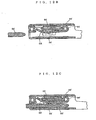
- Fig. 1 is a fragmentary longitudinal sectional view showing a connector of the first embodiment being connected with a counterpart connector.
- Fig. 2 is a left side view of the female terminal of the first embodiment.
- Fig. 3 is a plan view of the female terminal of the first embodiment.
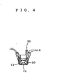
- Fig. 4 is a front view of the female terminal of the first embodiment.
- Fig. 5A is a sectional view along the line A- A of Fig. 2, and Fig. 5B is a sectional view along the line B- B of Fig. 2.
- Fig. 6 is a perspective view showing the female terminal of the first embodiment seen from a point behind, on the left and above.
- Fig. 7 is a perspective view of the female terminal of Fig. 6. The external wall of the front half part of the terminal proper is not shown.
- Fig. 8 is a perspective view of the female terminal of Fig. 7. The internal wall of the front half part of the terminal proper is not shown.
- Fig. 9 is a diagram showing the development of the female terminal of the first embodiment. It shows the female terminal before bending.
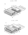
- Fig. 10A is a perspective view of the female terminal of the first embodiment. The female terminal is being inserted into the housing. It is seen from a point in front, on the right and above. The retainer is not shown. Fig. 10B is a similar perspective view of the female terminal after completion of insertion. In both diagrams, a part of the chamber on this side is cut away.
- Fig. 11 is a longitudinal sectional view showing a connector of the second embodiment which is not part of the invention. The connector is connected with a counterpart connector.
- Fig. 12A is a perspective view showing insertion of a conventional female terminal into a housing. Fig. 12B is a longitudinal sectional view of another conventional female terminal before insertion of a male terminal. Fig. 12C is a longitudinal sectional view of the conventional female terminal after insertion of the male terminal.
- In the following, embodiments of the present invention will be described with reference to the attached drawings. Fig. 2 through Fig. 6 show a female terminal T of a connector C of the first embodiment. Fig. 1, Fig. 10A and Fig. 10B show the connector C wherein this female terminal T is inserted in a housing H.
- As shown in Fig. 2 through Fig. 6, the female terminal T is provided with a terminal proper 10 having an approximately tubular front half part that can be inserted into a
chamber 51 of the housing H, aleaf spring 20 of which root end is integral to the front half of the terminal proper 10, and astabilizer 30 being on the outer side of the terminal proper 10. It should be noted that with regard to the female terminal T, the front- rear direction is the longitudinal direction. For example, in Fig. 4, it is the direction perpendicular to the paper. The direction of height substantially corresponds to the direction of flexing of the top end of theleaf spring 20; for example, in Fig. 3, it is the direction perpendicular to the paper. The direction of width substantially corresponds to the direction of width of the top end of theleaf spring 20; for example, in Fig. 2, it is the direction perpendicular to the paper. This system of directions is also applied to the housing H. Hence the front - rear direction, the height direction and the width direction of the female terminal T that is inserted in thechamber 51 are the front- rear direction, the height direction and the width direction of thechamber 51 of the housing H, respectively. - A
port 11 is opened in the front end of the above- mentioned terminal proper 10 to receive a male terminal TT. Asplicing part 12 for connecting an electric wire W is provided in the back thereof. Thissplicing part 12 is formed to have an approximately U- shaped section. Its upper edge portions are bent inward to crimp the conductor of the electric wire W. A longitudinally intermediate part of the terminal proper 10 is provided with a fixingpart 13 into which aretainer 60 of the housing H is to be fitted. This fixingpart 13 is formed into an approximately U- shape when seen from the side. As the upper edges of the fixingpart 13 are formed to be lower than the upper wall of the front half part of the terminal proper 10, theretainer 60 can be fitted into the fixingpart 13 as shown in Fig. 1. - As shown in Fig. 1, Fig. 5A, Fig. 5B and Fig. 8, the top end of the above-mentioned
leaf spring 20 extends forward inside the front half part of the terminal proper 10 and can be flexed in the height direction. When a male terminal TT is inserted, the top end of theleaf spring 20 will be pressed to contact the male terminal TT. At the root end of theleaf spring 20, around part 21, that bends around an axis approximately parallel to the front half part into an approximately circular arc in a position beyond the reach of the male terminal TT, is formed. Abead 22 that has a curved section to increase the flexural rigidity is formed ahead of theround part 21 of theleaf spring 20. Here bending around an axis approximately parallel to the front half part means bending in such a way that displacement takes place in the direction of height. Theround part 21 is formed into an approximately circular arc around an axis that is in the front- rear direction of the terminal proper 10. Examples of the sectional forms of the above- mentionedbeam 22 include approximately U- shaped form, approximately W- shaped form and their inverted forms. What is important is that when theleaf spring 20 is sectioned along a plane in the front- rear direction the moment of inertia of area along a neutral axis passing sidewise in the middle, in the thickness direction, of theleaf spring 20 is greater than that of a flat plate.Slits round part 21 from both side edges of the round part's root end in the width direction of the terminal proper 10. At the top end of the above- mentioned terminal proper 10, when necessary, aguide 15 is formed to cover a gap between the top end of theleaf spring 20 and the inner wall of the terminal proper 10. Thisguide 15 prevents inadvertent insertion of the male terminal TT or a screwdriver for inspection, etc. into the gap. - As shown in Fig. 1, Fig. 10A and Fig. 10B, when the terminal proper 10 is inserted into the
chamber 51 of the housing H, the above- mentionedstabilizer 30 will fit into agroove 52 that is formed in the front- rear direction and moves forward beyond alance 53 that is formed in the groove. Thestabilizer 30 will reach a position in front of thelance 53 and will be fixed there by thelance 53. Thestabilizer 30 having a face in the width direction is erected in the height direction at the front end of the terminal proper 10. In the present embodiment, thestabilizer 30 is provided on the upper side of the terminal proper 10. - As shown in Fig. 1, Fig. 10A and Fig. 10B, the above- mentioned housing H comprises a housing proper 50 in which through
chambers 51 are formed in the front- rear direction and aretainer 60 that fits into the housing proper 50 and penetrates into thechambers 51. The above- mentioned housing proper 50 is provided withgrooves 52 that are made in the height direction from the chambers, extend in the front- rear direction and receive thestabilizers 30, lances 53 that are formed in respective grooves to be flexed in the width direction of thechambers 51 and fix thestabilizers 30 by the front sides, andtesting windows 54 that allow access to thegrooves 52 in front of thelances 53 from the front side. The above- mentionedgrooves 52 are formed upward from thechambers 51. In Fig. 10A and Fig. 10B, the exemplifying connector C has a single row ofparallel chambers 51 arranged in the width direction. However, as shown in Fig. 12A, such rows ofchambers 51 may be arranged in several columns in the height direction. - The above- mentioned female terminal T is formed from a single sheet metal. As shown in Fig. 9, plural female terminals T, T ... in a developed form, with a runner connecting them together, are blanked out of a sheet metal. Next, various parts are bent to form the female terminals T, T ... into the final shape. After that, the respective female terminals T are separated from the runner N.
- In the above- mentioned first embodiment, after an electric wire W is connected to the
splicing part 12 of the terminal proper 10, when the female terminal T is inserted into achamber 51 of the housing H, thestabilizer 30 will fit into agroove 52 of the housing H (the state shown in Fig. 10A), then thestabilizer 30 will go beyond alance 53 of the housing H and will be fixed by thelance 53. This is the primary fixing of the female terminal T to the housing H (the state shown in Fig. 10B). Next, when theretainer 60 is forced into the housing H, theretainer 60 will fit into the fixingpart 13 of the terminal proper 10. This is the secondary fixing of the female terminal T to the housing H. When this connector C is opposed to a counterpart connector CC and its male terminals TT, TT ... are inserted into the female terminals T, T ..., eachleaf spring 20 will press to contact a male terminal TT to make mechanical connections and electric connections between both connectors C, CC (the state shown in Fig. 1). - In that case, as the
bead 22 is formed beyond theround part 21 of theleaf spring 20 on the top end side thereof, the flexural rigidity of theleaf spring 20 is greater and a sufficient contacting force is provided without provision of a reinforcing spring. Moreover, as no reinforcing spring is provided, the spring constant has no point of inflection, and the contacting force of each product is stabilized. Furthermore, as the flexural rigidity of theleaf spring 20 is greater, a sufficient contacting force is generated even if a contacting part of theleaf spring 20 is shifted forward close to the port. As a result, the length of insertion of the male terminal TT is shortened, and in turn, the housing HH of the counterpart connector CC that contains the male terminal TT is shortened and compactified and the tolerance to slant of the male terminal TT is also increased. This reduces troubles that a male terminal TT can not be inserted into a female terminal T. Thus the yield of connectors CC can be improved. Moreover, as theround part 21 is formed in a position beyond the reach of the male terminal TT, the radius of curvature of theround part 21 can be set larger by extensively using the interior of the front half part of the terminal proper in the height direction. This prevents generation of cracks in theround part 21 and stabilizes the contacting force. As thestabilizer 30 is provided at the top end of the terminal proper 10, if the female terminal T is inserted into achamber 51 of the housing H in a wrong orientation, thestabilizer 30 will catch on the entrance of thechamber 51 in the initial stage of insertion. Thus inverse insertion of the female terminal T is prevented reliably, and any damage to the housing H due to incorrect operation of the worker can be avoided. Furthermore, as thetest window 54 that directly leads to thestabilizer 30 is opened in the front of the housing H, when a test jig of which shape is identical to that of the male terminal TT is inserted into thetest window 54, the test jig will contact thestabilizer 30. Thus a continuity test, etc. can be made without giving any damage to the leaf spring, etc. As no reinforcing spring is used, the height of the female terminal T is lowered, and as theround part 21 is in a position beyond the reach of the male terminal TT and it does not require any space for the male terminal TT to crawl into beneath theleaf spring 20, the height of the female terminal T can be lowered further. Moreover, as thelance 53 of the housing H is flexed in the direction of width by thestabilizer 30 having a face set in the direction of width, there is no need of providing a space for flexing in the direction of height of the housing and the height can be reduced. As a result, the connector C can be compactified in the direction of height as much as possible. In particular, in the connector C whereinchambers 51 are arranged in the direction of height, several female terminals T are arranged in succession in the direction of height, and the number of walls betweenchambers 51 is larger. When the height of each female terminal T is lowered and the walls betweenchambers 51 are made thinner, the connector C can be compactified significantly in the direction of height. Because of this, the connector C is suitable as a connector for automobiles in which higher space utility is rigorously demanded. When thestabilizer 30 is provided on the lower side of the terminal proper 10, thegroove 52 is made downward from thechamber 51 and thelance 53 is provided to flex in the direction of width of thechamber 51, the connector C can be compactified in the direction of height just like the above- mentioned embodiment. - When the female terminal T is to be blanked out of a sheet metal, it is necessary to make sure that the respective parts do not interfere with each other in the developed form. These restraints may impair the degree of freedom of design. However, when the
round part 21 is bent into an approximately circular arc around an axis that is in the front- rear direction of the terminal proper 10 as is the case of the above- mentioned first embodiment, as shown in Fig. 9, if the female terminal T is formed from a single sheet metal, theleaf spring 20 and thesplicing part 12 in the developed form of the female terminal T hardly interfere with each other. Thus the degree of freedom of design is enhanced. - Connectors of this kind may undergo wear caused by microsliding. When a pair of connectors being connected with each other are subjected to temperature changes, they will undergo thermal deformation. As a result, the contacting surfaces of the female terminal and the male terminal slip relative to each other. When this is repeated, oxide films that are formed near the contacting surfaces will peel eventually. This is microsliding wear. Accumulation of this oxide film eventually causes imperfect contact. To prevent this, one way is to increase the contacting force of the leaf spring so that the slip hardly occurs. This, however, demands a large force in connecting the connectors together. It will be hard to use connectors having a large number of terminals. However, as is the case in the above-mentioned first embodiment, when slits 14, 14 are formed in a portion of terminal proper 10 that is continuous to the
round part 21 from both side edges of the round part's root end in the direction crossing the front- rear direction, theround part 21 shifts a little in the front- rear direction due to a deformation of the portion of the terminal proper betweenslits leaf spring 20 and the male terminal TT slip relative to each other. Thus the microsliding wear hardly occurs. Accordingly, imperfect contact due to oxide films hardly occurs. This means a high durability in, for example, an area of harsh temperature changes. In this case, as there is no need of microsliding wear preventive measures, such as increasing the contacting force of theleaf spring 20 by, for example, changing the radius of curvature of theround part 21, the force required for connecting the connector C can be set adequately and workability can be enhanced. Moreover, a connector C with a large number of terminals can be set. - Next, a second embodiment being not part of the invention will be described with reference to Fig. 11. This second embodiment differs from the above- mentioned first embodiment only in the configuration of the round part of the leaf spring, and other configurations are identical. Accordingly, identical marks are given to members that exhibit identical functions of the members of the first embodiment. The description of the first embodiment except a portion concerning the configuration of the round part of the leaf spring is quoted intact as the description of the configuration of the second embodiment.
- The configuration of the round part of the leaf spring of the second embodiment will be described. As shown in Fig. 11, the
round part 21 of the second embodiment is formed by bending a portion into an approximately circular arc around an axis that is in the right- left direction of the terminal proper 10, and slits 14, 14 are not formed. - In this second embodiment, as the
round part 21 is bent into an approximately circular arc around an axis that is in the right- left direction, it is necessary to some extent to consider interference between theleaf spring 20 and thesplicing part 12 in the developed form of the female terminal T. Moreover, asslits - The present invention includes an embodiment that is the first embodiment except no slits are formed. Further the second embodiment can be provided with formation of slits. In the first embodiment, the
round part 21 is formed by bending into an approximately circular arc around an axis that is in the front- rear direction of the terminal proper 10, and in the second embodiment, theround part 21 is formed by bending into an approximately circular arc around an axis that is in the left- right direction of the terminal proper 10, but the present invention includes only first embodiments having a round part (21) that is formed at the root end of said leaf spring (20) and bent around an axis lying approximately in said longitudinal direction of said front half part into an approximately circular arc in a position beyond the reach of said male terminal (TT), wherein the radius of curvature of the round part (21) extensively uses the interior of the front half part of the terminal proper (10) in the height direction.
Claims (3)
- A female terminal (T) for a connector (C) comprising:a terminal proper (10) having
a tubular front half part extending in a longitudinal direction from a front end to a back end and having height and width directions, respectively, which directions being both perpendicular to said longitudinal direction and being perpendicular to each other, which front half part can be inserted into a chamber (51) of a housing (H) of said connector (C) for reaching an inserted condition,
a port (11) that opens in the front end for, in an inserted condition, receiving a male terminal (TT),
a splicing part (12) that is in the back end and that is to be connected to an electric wire (W), and
a fixing part (13) into which, in the inserted condition, a retainer (60) of said housing (H) fits;a leaf spring (20) having
a root end that is integral to the front half part of said terminal proper (10), and
a top end extending inside the front half part of said terminal proper (10) to the front end in the longitudinal direction and being to be flexed in the height direction; and
a bead (22) that is formed ahead of a round part (21) of said leaf spring (20) on the top end side thereof and has a curved section to increase the flexural rigidity;
characterised in thata stabilizer (30) being erected in the height direction on the outer side at the front end of said terminal proper (10), having a face in the width direction, fitting into a groove (52) formed in the longitudinal direction and advancing beyond a lance (53) that is formed in the groove (52) and being fixed by the lance (53) in said inserted condition; the round part (21) that is formed at the root end of said leaf spring (20) and bent around an axis lying approximately in said longitudinal direction of said front half part into an approximately circular arc in a position beyond the reach of said male terminal (TT), wherein the radius of curvature of the round part (21) extensively uses the interior of the front half part of the terminal proper (10) in the height direction. - A female terminal (T) according to claim 1, characterized in that slits (14) are formed in a portion of the terminal proper (10) that is continuous to the round part (21) from both side edges of the root end of the round part (21) in the width direction of the terminal proper (10).
- A combination of a housing (H) of a connector (C) and a female terminal (T) according to claim 1 or 2, characterized by
a housing proper (50) having
said chambers (51)as through chambers formed in the longitudinal direction,
said grooves (52) made in the height direction from said chambers (51), extending in the longitudinal direction and receiving said stabilizers (30),
said lances (53) formed in said grooves (52) for being flexed in the width direction of said chambers (51) and for fixing said stabilizers (30) by the front end, and
test windows (54) that allow access to the grooves (52) in front of the lances (53) from the front end; and
said retainer (60) that fits into said housing proper (50) and penetrates into said chambers (51).
Applications Claiming Priority (2)
| Application Number | Priority Date | Filing Date | Title |
|---|---|---|---|
| JP21975398A JP3224369B2 (en) | 1998-07-16 | 1998-07-16 | Connector terminals and housing |
| JP21975398 | 1998-07-16 |
Publications (3)
| Publication Number | Publication Date |
|---|---|
| EP0977319A2 EP0977319A2 (en) | 2000-02-02 |
| EP0977319A3 EP0977319A3 (en) | 2000-12-20 |
| EP0977319B1 true EP0977319B1 (en) | 2006-05-03 |
Family
ID=16740470
Family Applications (1)
| Application Number | Title | Priority Date | Filing Date |
|---|---|---|---|
| EP99113384A Expired - Lifetime EP0977319B1 (en) | 1998-07-16 | 1999-07-10 | A female terminal for a connector and a housing therefor |
Country Status (5)
| Country | Link |
|---|---|
| US (1) | US6174208B1 (en) |
| EP (1) | EP0977319B1 (en) |
| JP (1) | JP3224369B2 (en) |
| KR (1) | KR100579653B1 (en) |
| DE (1) | DE69931110T2 (en) |
Families Citing this family (23)
| Publication number | Priority date | Publication date | Assignee | Title |
|---|---|---|---|---|
| JP3620786B2 (en) * | 2000-01-24 | 2005-02-16 | 矢崎総業株式会社 | Terminal bracket |
| US6398597B1 (en) * | 2001-02-09 | 2002-06-04 | Hon Hai Precision Ind. Co., Ltd. | Receptacle contact of a cable assembly and the cable assembly using the same |
| DE60218094T2 (en) * | 2001-09-07 | 2007-11-29 | Sumitomo Wiring Systems, Ltd., Yokkaichi | Terminal contact, connector equipped therewith and method of making the terminal contact |
| JP3763574B2 (en) * | 2003-03-14 | 2006-04-05 | 日本航空電子工業株式会社 | connector |
| US6905376B2 (en) * | 2003-04-15 | 2005-06-14 | J.S.T. Mfg. Co., Ltd. | Terminal |
| US7229324B2 (en) * | 2004-04-06 | 2007-06-12 | Fci Sa | High speed receptacle connector part |
| FR2869161B1 (en) * | 2004-04-19 | 2007-04-20 | Fci Sa | ELECTRIC CONTACT, AND ELECTRICAL CONNECTOR PART COMPRISING SUCH CONTACT |
| KR100808951B1 (en) * | 2006-12-14 | 2008-03-04 | 한국단자공업 주식회사 | Connector with low insert force |
| JP2008293722A (en) * | 2007-05-23 | 2008-12-04 | Sumitomo Wiring Syst Ltd | Connector |
| KR100897376B1 (en) * | 2007-06-25 | 2009-05-14 | 한국단자공업 주식회사 | Connector |
| JP5285985B2 (en) * | 2008-07-17 | 2013-09-11 | 矢崎総業株式会社 | Female terminal fitting |
| US8974256B2 (en) * | 2012-04-26 | 2015-03-10 | Sumitomo Wiring Systems, Ltd. | Terminal fitting and production method therefor |
| JP6027937B2 (en) | 2013-04-08 | 2016-11-16 | 矢崎総業株式会社 | connector |
| WO2014195749A1 (en) * | 2013-06-07 | 2014-12-11 | FCI Asia Pte. Ltd. | Cable connector |
| DE102013222941A1 (en) * | 2013-11-12 | 2015-05-13 | Zf Friedrichshafen Ag | Connectors |
| US10230189B2 (en) | 2013-12-03 | 2019-03-12 | Amphenol Fci Asia Pte Ltd | Connector and pin receiving contact for such a connector |
| US20150275952A1 (en) * | 2014-03-25 | 2015-10-01 | Fritz Stepper Gmbh & Co. Kg | Plug-on part for a plug connector |
| US9437991B2 (en) * | 2014-07-10 | 2016-09-06 | Schneider Electric USA, Inc. | Load center bus having integral stabs with formed shapes |
| US9472885B2 (en) * | 2014-12-08 | 2016-10-18 | Delphi Technologies, Inc. | Electrical connector assembly with low terminal insertion force |
| JP1599728S (en) * | 2017-07-07 | 2018-03-19 | ||
| CN109411934B (en) * | 2017-08-16 | 2021-11-19 | 富士康(昆山)电脑接插件有限公司 | Electrical connector |
| MX2020009647A (en) | 2018-03-16 | 2021-02-26 | Fci Usa Llc | High density electrical connectors. |
| CN111370381B (en) * | 2020-03-27 | 2022-04-01 | 广东芯聚能半导体有限公司 | Connecting assembly, power semiconductor and connecting method suitable for power semiconductor |
Citations (1)
| Publication number | Priority date | Publication date | Assignee | Title |
|---|---|---|---|---|
| JPH05135819A (en) * | 1991-11-12 | 1993-06-01 | Amp Japan Ltd | Receptacle contact |
Family Cites Families (8)
| Publication number | Priority date | Publication date | Assignee | Title |
|---|---|---|---|---|
| US3083351A (en) * | 1961-04-10 | 1963-03-26 | Jr Auker J Nielsen | Electrical receptacle |
| JP2767732B2 (en) * | 1993-01-19 | 1998-06-18 | 矢崎総業株式会社 | Connection terminal unlocking mechanism |
| JP2581476Y2 (en) * | 1993-04-13 | 1998-09-21 | 住友電装株式会社 | connector |
| JPH08106944A (en) * | 1994-10-03 | 1996-04-23 | Tokai Rika Co Ltd | Electric connector and housing of this electric connector |
| JPH0955246A (en) | 1995-08-15 | 1997-02-25 | Amp Japan Ltd | Electric terminal |
| JPH09232021A (en) | 1996-02-20 | 1997-09-05 | Amp Japan Ltd | Female electric terminal |
| JP3062928B2 (en) * | 1996-04-26 | 2000-07-12 | 日本航空電子工業株式会社 | contact |
| DE69702142T2 (en) * | 1996-10-17 | 2001-02-01 | Whitaker Corp | ELECTRICAL CONNECTOR WITH A HOUSING AND AN ELECTRICAL CONTACT ELEMENT |
-
1998
- 1998-07-16 JP JP21975398A patent/JP3224369B2/en not_active Expired - Lifetime
-
1999
- 1999-07-07 US US09/348,393 patent/US6174208B1/en not_active Expired - Lifetime
- 1999-07-10 EP EP99113384A patent/EP0977319B1/en not_active Expired - Lifetime
- 1999-07-10 DE DE69931110T patent/DE69931110T2/en not_active Expired - Lifetime
- 1999-07-16 KR KR1019990028888A patent/KR100579653B1/en not_active IP Right Cessation
Patent Citations (1)
| Publication number | Priority date | Publication date | Assignee | Title |
|---|---|---|---|---|
| JPH05135819A (en) * | 1991-11-12 | 1993-06-01 | Amp Japan Ltd | Receptacle contact |
Also Published As
| Publication number | Publication date |
|---|---|
| KR100579653B1 (en) | 2006-05-15 |
| DE69931110T2 (en) | 2006-11-23 |
| JP2000036350A (en) | 2000-02-02 |
| KR20000011776A (en) | 2000-02-25 |
| EP0977319A3 (en) | 2000-12-20 |
| US6174208B1 (en) | 2001-01-16 |
| JP3224369B2 (en) | 2001-10-29 |
| DE69931110D1 (en) | 2006-06-08 |
| EP0977319A2 (en) | 2000-02-02 |
Similar Documents
| Publication | Publication Date | Title |
|---|---|---|
| EP0977319B1 (en) | A female terminal for a connector and a housing therefor | |
| EP0986141B1 (en) | A female terminal for a connector and a housing therefor | |
| EP0932917B1 (en) | Electrical connector having a housing and an electrical contact | |
| US7300319B2 (en) | Electrical contact | |
| EP1923962B1 (en) | A connector and method of preassembling it | |
| EP1936749B1 (en) | A terminal fitting, a connector and a forming method | |
| JP2675698B2 (en) | Electric contact terminal | |
| US6679738B2 (en) | Female terminal | |
| EP1990867A2 (en) | Electrical contact | |
| EP1271705B1 (en) | Connector with open-stopping means for retainer | |
| US10910754B2 (en) | Stacked connector | |
| US10819060B2 (en) | Stacked connector | |
| US6585544B2 (en) | Terminal fitting | |
| US4717361A (en) | Contact for connector | |
| US6589080B2 (en) | Terminal fitting and a connector | |
| EP0981184A1 (en) | Connector housing with hinged retainer | |
| CN112909608A (en) | Terminal fitting | |
| JP4520874B2 (en) | Female terminals and connectors | |
| CN110581370A (en) | Terminal and connector | |
| JP3784450B2 (en) | Receptacle type terminal | |
| WO2023032699A1 (en) | Female connector | |
| JP7418305B2 (en) | Wire pressure welding structure | |
| TWI752408B (en) | Connectors and Terminals | |
| US11990700B2 (en) | Connector with front mask | |
| JP3224370B2 (en) | Connector terminals and housing |
Legal Events
| Date | Code | Title | Description |
|---|---|---|---|
| PUAI | Public reference made under article 153(3) epc to a published international application that has entered the european phase |
Free format text: ORIGINAL CODE: 0009012 |
|
| AK | Designated contracting states |
Kind code of ref document: A2 Designated state(s): DE FR GB |
|
| AX | Request for extension of the european patent |
Free format text: AL;LT;LV;MK;RO;SI |
|
| RIN1 | Information on inventor provided before grant (corrected) |
Inventor name: CHEN, PING, JAPAN SOLDERLESS TERM. MFG. CO., LTD. |
|
| PUAL | Search report despatched |
Free format text: ORIGINAL CODE: 0009013 |
|
| AK | Designated contracting states |
Kind code of ref document: A3 Designated state(s): AT BE CH CY DE DK ES FI FR GB GR IE IT LI LU MC NL PT SE |
|
| AX | Request for extension of the european patent |
Free format text: AL;LT;LV;MK;RO;SI |
|
| RIC1 | Information provided on ipc code assigned before grant |
Free format text: 7H 01R 13/436 A, 7H 01R 13/115 B, 7H 01R 4/18 B, 7H 01R 13/422 B |
|
| 17P | Request for examination filed |
Effective date: 20010525 |
|
| AKX | Designation fees paid |
Free format text: DE FR GB |
|
| 17Q | First examination report despatched |
Effective date: 20020917 |
|
| GRAP | Despatch of communication of intention to grant a patent |
Free format text: ORIGINAL CODE: EPIDOSNIGR1 |
|
| GRAS | Grant fee paid |
Free format text: ORIGINAL CODE: EPIDOSNIGR3 |
|
| GRAA | (expected) grant |
Free format text: ORIGINAL CODE: 0009210 |
|
| AK | Designated contracting states |
Kind code of ref document: B1 Designated state(s): DE FR GB |
|
| REG | Reference to a national code |
Ref country code: GB Ref legal event code: FG4D |
|
| REF | Corresponds to: |
Ref document number: 69931110 Country of ref document: DE Date of ref document: 20060608 Kind code of ref document: P |
|
| ET | Fr: translation filed | ||
| PLBE | No opposition filed within time limit |
Free format text: ORIGINAL CODE: 0009261 |
|
| STAA | Information on the status of an ep patent application or granted ep patent |
Free format text: STATUS: NO OPPOSITION FILED WITHIN TIME LIMIT |
|
| 26N | No opposition filed |
Effective date: 20070206 |
|
| PGFP | Annual fee paid to national office [announced via postgrant information from national office to epo] |
Ref country code: FR Payment date: 20100802 Year of fee payment: 12 Ref country code: DE Payment date: 20100715 Year of fee payment: 12 |
|
| PGFP | Annual fee paid to national office [announced via postgrant information from national office to epo] |
Ref country code: GB Payment date: 20100726 Year of fee payment: 12 |
|
| GBPC | Gb: european patent ceased through non-payment of renewal fee |
Effective date: 20110710 |
|
| REG | Reference to a national code |
Ref country code: FR Ref legal event code: ST Effective date: 20120330 |
|
| PG25 | Lapsed in a contracting state [announced via postgrant information from national office to epo] |
Ref country code: FR Free format text: LAPSE BECAUSE OF NON-PAYMENT OF DUE FEES Effective date: 20110801 Ref country code: DE Free format text: LAPSE BECAUSE OF NON-PAYMENT OF DUE FEES Effective date: 20120201 |
|
| REG | Reference to a national code |
Ref country code: DE Ref legal event code: R119 Ref document number: 69931110 Country of ref document: DE Effective date: 20120201 |
|
| PG25 | Lapsed in a contracting state [announced via postgrant information from national office to epo] |
Ref country code: GB Free format text: LAPSE BECAUSE OF NON-PAYMENT OF DUE FEES Effective date: 20110710 |