EP0976641B1 - Assembling of an operating unit with a steering column of a motor vehicle - Google Patents
Assembling of an operating unit with a steering column of a motor vehicle Download PDFInfo
- Publication number
- EP0976641B1 EP0976641B1 EP99401863A EP99401863A EP0976641B1 EP 0976641 B1 EP0976641 B1 EP 0976641B1 EP 99401863 A EP99401863 A EP 99401863A EP 99401863 A EP99401863 A EP 99401863A EP 0976641 B1 EP0976641 B1 EP 0976641B1
- Authority
- EP
- European Patent Office
- Prior art keywords
- ring
- tube body
- bearing
- assembly
- tube
- Prior art date
- Legal status (The legal status is an assumption and is not a legal conclusion. Google has not performed a legal analysis and makes no representation as to the accuracy of the status listed.)
- Expired - Lifetime
Links
Images


Classifications
-
- B—PERFORMING OPERATIONS; TRANSPORTING
- B62—LAND VEHICLES FOR TRAVELLING OTHERWISE THAN ON RAILS
- B62D—MOTOR VEHICLES; TRAILERS
- B62D1/00—Steering controls, i.e. means for initiating a change of direction of the vehicle
- B62D1/02—Steering controls, i.e. means for initiating a change of direction of the vehicle vehicle-mounted
- B62D1/16—Steering columns
-
- F—MECHANICAL ENGINEERING; LIGHTING; HEATING; WEAPONS; BLASTING
- F16—ENGINEERING ELEMENTS AND UNITS; GENERAL MEASURES FOR PRODUCING AND MAINTAINING EFFECTIVE FUNCTIONING OF MACHINES OR INSTALLATIONS; THERMAL INSULATION IN GENERAL
- F16C—SHAFTS; FLEXIBLE SHAFTS; ELEMENTS OR CRANKSHAFT MECHANISMS; ROTARY BODIES OTHER THAN GEARING ELEMENTS; BEARINGS
- F16C35/00—Rigid support of bearing units; Housings, e.g. caps, covers
- F16C35/04—Rigid support of bearing units; Housings, e.g. caps, covers in the case of ball or roller bearings
- F16C35/06—Mounting or dismounting of ball or roller bearings; Fixing them onto shaft or in housing
- F16C35/07—Fixing them on the shaft or housing with interposition of an element
- F16C35/077—Fixing them on the shaft or housing with interposition of an element between housing and outer race ring
-
- F—MECHANICAL ENGINEERING; LIGHTING; HEATING; WEAPONS; BLASTING
- F16—ENGINEERING ELEMENTS AND UNITS; GENERAL MEASURES FOR PRODUCING AND MAINTAINING EFFECTIVE FUNCTIONING OF MACHINES OR INSTALLATIONS; THERMAL INSULATION IN GENERAL
- F16C—SHAFTS; FLEXIBLE SHAFTS; ELEMENTS OR CRANKSHAFT MECHANISMS; ROTARY BODIES OTHER THAN GEARING ELEMENTS; BEARINGS
- F16C2326/00—Articles relating to transporting
- F16C2326/20—Land vehicles
- F16C2326/24—Steering systems, e.g. steering rods or columns
Definitions
- the present invention relates to assembly a set of commands with a column of motor vehicle steering, as defined in the preamble of claim 1 and describes in document DE-U-7807568.
- the steering column has a steering, which is mounted in a tube-body.
- the tube-body is arranged in at least one support element, which is fixed to the structure of the vehicle. All is located under the steering wheel, and it is mounted on the tube-body.
- the purpose of the present invention is to provide an assembly, which avoids the disadvantages described above; and which allows to realize directly mounting the control assembly in the tube-body, that is to say without any adjustment in chain manufacturing, while obtaining the position exact angular requested.
- Assembling a set of controls with a motor vehicle steering column according to the invention is constituted by a column of steering, which has a mounted steering shaft free to rotate in a body tube using two bearings.
- a flywheel is connected to the shaft of direction, and the set of controls is arranged under the steering wheel and is mounted on the body tube.
- said tube-body is arranged in at least one element support fixed to the structure of the motor vehicle.
- the bearing which is located on the side of the steering wheel, is disposed between the body tube and the steering shaft.
- Said assembly comprises a material ring plastic, which is arranged between said bearing and the tube-body.
- Said ring comprises in the direction axial a central portion and an outer portion. The central portion receives the bearing, and the outer portion is the axial extension of the central portion, the outer portion being located on the side of the control unit and the steering wheel.
- Said outer portion is provided with at least a shape, which is correctly positioned angularly with respect to the interface between one support elements and the structure of the vehicle.
- Said shape is arranged and sized for interpenetrate with a conjugate form, which is arranged in the control unit, so that this set of controls is mounted on the tube-body at the exact angular position desired by relationship to the interface between one of the support elements and the structure of the vehicle.
- the inner portion of the ring is provided with radial reinforcing ribs, which are arranged on the internal face of said portion interior.
- the ring has at least one form of assembly, which is constituted by a notch, which cooperates with a nipple fitted in the set of controls.
- the ring has at least one form of assembly, which is constituted by a nipple, which cooperates with a notch fitted in the set of controls.
- the tube-body is arranged in two support elements attached to the vehicle structure.
- Assembling a set of controls with a motor vehicle steering column thus has the advantage of allowing the mounting in the tube-body without any adjustment, everything ensuring a correct angular position by relative to the chosen reference, which can be the axis or the interface with between an element support and structure of the vehicle.
- the plastic ring due to its material allows to adapt to the tolerances of manufacture of the tube-body.
- This assembly also has other advantages.
- the internal buffers which are made on the tube-body, positively stop the ring, due to interference of the ring with the stops internal; and this up to a known effort, which corresponds to normal use of the column.
- the ring In case of shock, when the forces transmitted to the turnover are very important and greater than the previous known effort, the ring has the possibility to pass over the bumpers.
- the sliding of the ring on the stops is relatively constant, and allows absorption of energy controlled during the impact.
- the axial position of the mounting of the ring on the tube may vary without affecting subsequent operation energy absorption in case of shock.
- the invention relates to a column of motor vehicle management, all of which located near the driver's steering wheel is shown in Figure 6.
- the steering column has a steering shaft 1, which is mounted in a body tube 3 along axis 11 of the steering shaft 1.
- the steering shaft 1 is mounted to rotate freely in the tube-body 3 with respect to its axis 11. This mounting is carried out via two bearings 5 and 6.
- the bearing 5 is disposed between the body tube 3 and the steering shaft 1, and it is located on the steering wheel side.
- the tube-body 3 is provided with a reinforcement square 15, which is arranged inside a support element 7.
- the support element 7 consists of a base 86, which is provided at each of its two ends with a amount referenced 87 and 88.
- the support element 7 is connected to the structure 13 of the motor vehicle with an interface 85.
- the tube-body assembly 3 with its reinforcement square 15 is disposed inside the two uprights 87 and 88 of the support element 7. Said uprights are substantially parallel to the axis 11.
- the support element 8 is arranged on the side of the bearing 6, that is to say opposite of the steering wheel of the driver.
- the support element 8 consists of a base 91, which is provided with each of its two ends of an amount referenced 92 and 93.
- the support element 8 is connected to the structure 13 of the motor vehicle with an interface 90.
- the whole of the tube-body 3 is disposed at the interior of the two uprights 92 and 93 of the support element 8.
- the said amounts 92 and 93 are substantially parallel to the axis 11 of the shaft of direction 1.
- the invention can be applied to two types of steering columns: the steering columns fixed, and adjustable steering columns.
- the support elements 7 and 8 are rigidly connected to the entire tube-body 3. This can be by example by welding or any other means.
- the entire body-tube 3 is adjustable with respect to the support element 7 and with respect to the support element 8.
- the entire tube-body 3 is connected to the support element 8 by a hinge pin 94 substantially perpendicular to axis 11.
- the tube-body 3 with its reinforcement square 15 is connected to the support element 7 by an adjustment system in position relative to said support element 7.
- This position adjustment system is locked to the position chosen by a clamping device 9, along a clamping axis 12, which is substantially perpendicular to the axis 11 of the steering shaft 1.
- the clamping axis 12 passes through the reinforcement square 15 of the tube-body 3, and the two uprights 87 and 88 of the support element 7.
- the clamping device 9 is controlled by an operating assembly 10, which can be manual as in figure 6 or any other type such as a remote order.
- the device clamp 9 is put in the locked position or unlocked by the operating assembly 10.
- the clamping axis 12 can possibly cross the tube-body 3, which is not not necessarily equipped with a reinforcement square 15.
- the different elements making up the clamp 9 are mounted, either on a clamp rod clamping axis 12, or by any other means.
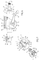
- the invention relates to an assembly shown in Figure 1, which is an exploded view in perspective of all of assembly.
- Assembly concerns the assembly of a set of controls 2 with a steering column of motor vehicle described above.
- the set of controls 2 is arranged under the driver's steering wheel 14.
- the steering wheel is connected to the end 21 of the steering shaft 1.
- the control assembly is mounted on the body tube 3, and it is thus located between the flywheel 14 and the tube-body 3.
- the assembly according to the invention comprises a plastic ring 4, which is arranged between the bearing 5 and the tube-body 3.
- the ring 4 comprises in the axial direction a central portion 30, an inner portion 31 and an outer portion 32.
- the central portion 30 receives the bearing 5, and the outer portion 32 is the axial extension of the central portion 30.
- the outer portion 32 is thus located on the side of the control assembly 2 and of the steering wheel 14.
- the outer portion 32 is provided with two forms referenced respectively 43 and 44, which are correctly positioned angularly by compared to the interface 85 or / and 90 located between the support element 7 and the support element respectively 8 with structure 13 of the vehicle automobile.
- Forms 43 and 44 are arranged and sized to interpenetrate with respectively a conjugate form referenced 73 and 74, which are arranged in the set of controls 2 ; so that this set of controls is mounted on the tube-body 3 at the exact angular position desired with respect to interface 85 or / and 90 between respectively one of the support elements 7 and 8 and the structure 13 of the vehicle.
- the plastic ring 4 has one side outer 33, an inner side face 34, and a outer side face 35.
- the ring 4 is provided with a partition 36 disposed between the portion central 30 and the inner portion 31.
- the bearing 5 has an inner ring 26 and a outer ring 27, the inner side face of which is referenced 28 and the outer side face is referenced 29.
- the bearing 5 is forcibly mounted in the ring 4 by engaging in the internal face 42 of the outer portion 32, and the bearing which forcibly engages in this internal face 42 comes lean against a bottom 41 of the partition 36.
- the partition 36 has an internal face 37 arranged so as to allow the steering shaft to pass freely 1. From plus, the inner portion 31 of the ring 4 is provided with radial reinforcing ribs 39 which are arranged on the internal face 38 of said portion interior 31.
- the ring 4 has two forms of assembly which consist of a notch 43 and 44. These notches 43 and 44 cooperate respectively with a nipple 73 and 74 which is arranged in all of commands 2.
- each of the notches has a shape substantially rectangular with respectively a bottom 45 and 46, and sides 47 and 48. These sides 47 and 48 are substantially parallel to the axis 11 and the notches 43 and 44 in the case shown are diametrically opposite.
- the set of controls 2 under the steering wheel 14 has a housing 70 sized so that it can come engage the tube-body 3.
- This housing 70 is equipped with two nipples referenced 73 and 74, these nipples having a vertex 75 and 76 respectively and sides 77 and 78.
- These nipples 73 and 74 are diametrically opposite and are sized to be able to fit exactly in notches 43 and 44 arranged in the outer portion 32 of the ring 4.
- the tube-body has at its end 52 a face internal 50 and an external face 51, and it ends at the end by an outer end face 53.
- the tube-body 3 is provided with two notches referenced 55 and 56 which are arranged at its end 52.
- the notches 55 and 56 have the same angular orientation and have a width and a depth greater than the width and depth of the notches corresponding 43 and 44 of the ring 4; in a way to ability to adjust angle of ring 4 during the mounting of said ring 4 in the tube-body 3.
- the plastic ring 4 is engaged in the tube-body 3 and it is axially blocked in the tube-body 3 between internal buffers 54 and crimps.
- the internal buffers 54 are even arranged on the internal face 50 of the tube-body 3, and the crimps are arranged at the end 52 of the tube-body 3.
- Each of the crimps is obtained by two grooves 61, which are parallel and of direction axial in order to produce a tongue 62, which is folded against the outer lateral face 29 of the bearing 5.
- each tongue 62 passes through an opening 49, which is arranged in the portion outer 32 of the ring 4.
- Each of the notches 55 and 56 has a shape substantially rectangular with respectively a bottom 57 and 58 and sides 59 and 60.
- the ring 4 is provided with two pins 63 and 64, which are arranged in the outer portion 32.
- the ring 4 is locked axially in the tube-body 3 between the internal buffers 54 and crimps.
- the internal buffers 54 are arranged on the face internal 50 of the tube-body 3, and the crimps are arranged at the end 52 of the tube-body 3.
- Each of the crimps is obtained by two grooves 61 which are parallel and axial direction to achieve a tongue 62, which is folded against the face lateral lateral 29 of the bearing 5.
- Each tongue 62 passes through an opening 49, which is fitted in the outer portion 32 of the ring 4.
- pins 63 and 64 are diametrically opposed or respectively a vertex 65 and 66 and sides 67 and 68, which are substantially parallel to the axis 11.
- Nipples 63 and 64 are sized to cooperate with notches referenced 79 and 80 respectively which are fitted in the set of controls 2.
- the control assembly 2 then has in its housing 70, two diametrically opposite notches 79 and 80 which have a background 81 and 82 respectively and sides 83 and 84.
Landscapes
- Engineering & Computer Science (AREA)
- General Engineering & Computer Science (AREA)
- Mechanical Engineering (AREA)
- Chemical & Material Sciences (AREA)
- Combustion & Propulsion (AREA)
- Transportation (AREA)
- Steering Controls (AREA)
Description
La présente invention se rapporte à l'assemblage d'un ensemble de commandes avec une colonne de direction de véhicule automobile, tel que défini dans le préambule de la revendication 1 et décrit dans le document DE-U-7807568.The present invention relates to assembly a set of commands with a column of motor vehicle steering, as defined in the preamble of claim 1 and describes in document DE-U-7807568.
La colonne de direction comporte un arbre de direction, qui est monté dans un tube-corps. Le tube-corps est disposé dans au moins un élément support, qui est fixé à la structure du véhicule. L'ensemble de commandes est disposé sous le volant, et il est monté sur le tube-corps.The steering column has a steering, which is mounted in a tube-body. The tube-body is arranged in at least one support element, which is fixed to the structure of the vehicle. All is located under the steering wheel, and it is mounted on the tube-body.
Il existe des colonnes de direction fixes, ou réglables en hauteur et en profondeur, dont l'ensemble de commandes sous le volant appelé aussi "commodo" se monte directement dans le tube-corps, afin d'être disposé, suivant l'axe de direction, entre le volant et le tube-corps.There are fixed steering columns, or adjustable in height and depth, including the set of controls under the steering wheel also called "commodo" is mounted directly in the body tube, in order to be arranged, along the axis of direction, between the steering wheel and the body tube.
Dans ces types d'assemblages connus, il est nécessaire, lors du montage de l'ensemble de commandes en chaíne de fabrication, d'effectuer un réglage en position angulaire par rapport à l'axe de direction, afin de rattraper les tolérances de fabrication et de montage des différents éléments de la colonne de direction intervenant dans la position angulaire finale de l'ensemble de commandes.In these types of known assemblies, it is necessary, when mounting the set of orders in the production line, to carry out a adjustment in angular position relative to the axis of direction, in order to catch up with the tolerances of manufacture and assembly of the various elements of the steering column intervening in the position final angularity of the set of controls.
La but de la présente invention est de proposer un assemblage, qui évite les inconvénients décrits ci-dessus ; et qui permette de réaliser directement le montage de l'ensemble de commandes dans le tube-corps, c'est-à-dire sans aucun réglage en chaíne de fabrication, tout en permettant d'obtenir la position angulaire exacte demandée.The purpose of the present invention is to provide an assembly, which avoids the disadvantages described above; and which allows to realize directly mounting the control assembly in the tube-body, that is to say without any adjustment in chain manufacturing, while obtaining the position exact angular requested.
L'assemblage d'un ensemble de commandes avec une colonne de direction de véhicule automobile selon l'invention, est constitué par une colonne de direction, qui comporte un arbre de direction monté libre en rotation dans un tube-corps à l'aide de deux roulements. Un volant est relié à l'arbre de direction, et l'ensemble de commandes est disposé sous le volant et est monté sur le tube-corps. Ledit tube-corps est disposé dans au moins un élément support fixé à la structure du véhicule automobile. Le roulement, qui est situé du côté du volant, est disposé entre le tube-corps et l'arbre de direction.Assembling a set of controls with a motor vehicle steering column according to the invention is constituted by a column of steering, which has a mounted steering shaft free to rotate in a body tube using two bearings. A flywheel is connected to the shaft of direction, and the set of controls is arranged under the steering wheel and is mounted on the body tube. said tube-body is arranged in at least one element support fixed to the structure of the motor vehicle. The bearing, which is located on the side of the steering wheel, is disposed between the body tube and the steering shaft.
Ledit assemblage comporte une bague en matière plastique, qui est agencée entre ledit roulement et le tube-corps. Ladite bague comporte dans le sens axial une portion centrale et une portion extérieure. La portion centrale reçoit le roulement, et la portion extérieure est le prolongement axial de la portion centrale, la portion extérieure étant située du côté de l'ensemble de commande et du volant.Said assembly comprises a material ring plastic, which is arranged between said bearing and the tube-body. Said ring comprises in the direction axial a central portion and an outer portion. The central portion receives the bearing, and the outer portion is the axial extension of the central portion, the outer portion being located on the side of the control unit and the steering wheel.
Ladite portion extérieure est munie d'au moins une forme, qui est correctement positionnée angulairement par rapport à l'interface entre l'un des éléments support et la structure du véhicule. Ladite forme est agencée et dimensionnée pour s'interpénétrer avec une forme conjuguée, qui est aménagée dans l'ensemble de commandes, de manière que cet ensemble de commandes soit monté sur le tube-corps à la position angulaire exacte désirée par rapport à l'interface entre l'un des éléments support et la structure du véhicule. Said outer portion is provided with at least a shape, which is correctly positioned angularly with respect to the interface between one support elements and the structure of the vehicle. Said shape is arranged and sized for interpenetrate with a conjugate form, which is arranged in the control unit, so that this set of controls is mounted on the tube-body at the exact angular position desired by relationship to the interface between one of the support elements and the structure of the vehicle.
Avantageusement, la bague en matière plastique comporte :
- la portion centrale dans laquelle est monté le roulement ;
- la portion extérieure, qui est munie de la forme d'assemblage avec la forme conjuguée de l'ensemble de commandes ;
- une portion intérieure, qui est séparée de la portion centrale par une cloison, le roulement venant s'appuyer contre le fond de ladite cloison.
- the central portion in which the bearing is mounted;
- the outer portion, which is provided with the form of assembly with the combined form of the set of controls;
- an inner portion, which is separated from the central portion by a partition, the bearing pressing against the bottom of said partition.
De plus, la portion intérieure de la bague est munie de nervures radiales de renfort, qui sont agencées sur la face interne de ladite portion intérieure.In addition, the inner portion of the ring is provided with radial reinforcing ribs, which are arranged on the internal face of said portion interior.
Selon un premier type de réalisation, la bague possède au moins une forme d'assemblage, qui est constituée par une encoche, qui coopère avec un téton aménagé dans l'ensemble de commandes.According to a first type of embodiment, the ring has at least one form of assembly, which is constituted by a notch, which cooperates with a nipple fitted in the set of controls.
Selon un autre type de réalisation, la bague possède au moins une forme d'assemblage, qui est constituée par un téton, qui coopère avec une encoche aménagée dans l'ensemble de commandes.According to another type of embodiment, the ring has at least one form of assembly, which is constituted by a nipple, which cooperates with a notch fitted in the set of controls.
Dans le cas de colonnes de direction fixes, le tube-corps est disposé dans deux éléments supports fixés à la structure du véhicule.In the case of fixed steering columns, the tube-body is arranged in two support elements attached to the vehicle structure.
Dans le cas de colonnes de direction réglables, le tube-corps est disposé dans :
- un premier élément support qui est constitué d'une embase ayant à chacune de ses deux extrémités un montant, le tube-corps étant disposé à l'intérieur des deux montants de l'élément support, lesdits montants étant sensiblement parallèles à l'axe de l'arbre de direction,
- un deuxième élément support, qui est constitué d'une embase ayant à chacune de ses deux extrémités un montant, le tube-corps étant disposé à l'intérieur des deux montants de l'élément support, lesdits montants étant sensiblement parallèles à l'axe de l'arbre de direction, et ledit tube-corps étant relié à l'élément support par un axe d'articulation,
- le tube-corps a un système de réglage en position par rapport à l'élément support, qui est verrouillé à la position choisie par un dispositif de serrage ayant un axe de serrage, qui traverse un carré renfort du tube-corps, et les deux montants, le dispositif de serrage étant commandé par un ensemble de manoeuvre .
- a first support element which consists of a base having at each of its two ends a post, the tube-body being disposed inside the two posts of the support member, said posts being substantially parallel to the axis of the steering shaft,
- a second support element, which consists of a base having at each of its two ends a post, the body-tube being disposed inside the two posts of the support member, said posts being substantially parallel to the axis of the steering shaft, and said body tube being connected to the support element by a hinge pin,
- the body-tube has a position adjustment system relative to the support element, which is locked in the position chosen by a clamping device having a clamping axis, which passes through a reinforcement square of the body-tube, and both uprights, the clamping device being controlled by an operating assembly.
Selon une architecture de l'invention :
- la bague est munie de deux encoches, qui sont agencées dans la portion extérieure ;
- le tube-corps est muni de deux encoches, qui sont agencées à son extrémité ; les encoches ont la même orientation angulaire et ont une largeur plus grande que le largeur des encoches correspondantes de la bague ; de manière à pouvoir réaliser le réglage angulaire de la bague, lors du montage de ladite bague dans le tube-corps ;
- la bague est bloquée axialement dans le tube-corps entre des butoirs internes et des sertissages ; les butoirs internes sont aménagés sur la face interne du tube-corps, et les sertissages sont aménagés à l'extrémité du tube-corps ; chacun des sertissages étant obtenu par deux saignées parallèles et de sens axial pour réaliser une languette, qui est rabattue contre la face latérale extérieure du roulement, chaque languette traversant une ouverture aménagée dans la portion extérieure de la bague.
- the ring is provided with two notches, which are arranged in the outer portion;
- the tube-body is provided with two notches, which are arranged at its end; the notches have the same angular orientation and have a width greater than the width of the corresponding notches of the ring; so as to be able to carry out the angular adjustment of the ring, during the mounting of said ring in the tube-body;
- the ring is locked axially in the body-tube between internal buffers and crimps; the internal buffers are arranged on the internal face of the tube-body, and the crimps are arranged at the end of the tube-body; each of the crimps being obtained by two parallel grooves and in an axial direction to produce a tongue, which is folded against the external lateral face of the bearing, each tongue passing through an opening formed in the external portion of the ring.
Selon une autre architecture de l'invention :
- la bague est munie de deux tétons, qui sont agencés dans la portion extérieure ;
- la bague est bloquée axialement dans le tube-corps entre des butoirs internes et des sertissages ; les butoirs internes sont aménagés sur la face interne du tube-corps, et les sertissages sont aménagés à l'extrémité du tube-corps ; chacun des sertissages étant obtenu par deux saignées parallèles et de sens axial pour réaliser une languette, qui est rabattue contre la face latérale extérieure du roulement, chaque languette traversant une ouverture aménagée dans la portion extérieure de la bague.
- the ring is provided with two pins, which are arranged in the outer portion;
- the ring is locked axially in the body-tube between internal buffers and crimps; the internal buffers are arranged on the internal face of the tube-body, and the crimps are arranged at the end of the tube-body; each of the crimps being obtained by two parallel grooves and in an axial direction to produce a tongue, which is folded against the external lateral face of the bearing, each tongue passing through an opening formed in the external portion of the ring.
Un procédé de montage d'une colonne de direction de véhicule automobile munie de l'assemblage de l'invention comporte :
- l'engagement du roulement dans la bague plastique, afin d'obtenir le sous-ensemble roulement-bague plastique ;
- l'introduction du sous-ensemble roulement-bague dans le tube-corps avec orientation angulaire correcte par rapport à l'axe de serrage ;
- la pénétration du sous-ensemble roulement-bague jusqu'à ce que la bague vienne en appui contre les butoirs internes, puis rabattement des languettes de sertissage contre la face latérale extérieure du roulement, afin d'assurer le blocage axial du sous-ensemble roulement-bague dans le tube-corps ;
- l'engagement de l'arbre de direction dans le roulement avec mise en place axiale dudit arbre de direction par rapport au tube-corps ; et
- le montage du tube-corps dans l'élément support ou les éléments supports.
- engaging the bearing in the plastic ring, in order to obtain the bearing-plastic ring sub-assembly;
- the introduction of the bearing-ring sub-assembly into the tube-body with correct angular orientation relative to the clamping axis;
- penetration of the bearing-ring sub-assembly until the ring comes to bear against the internal buffers, then folding of the crimping tabs against the external lateral face of the bearing, in order to ensure the axial locking of the bearing sub-assembly -ring in the tube-body;
- engaging the steering shaft in the bearing with axial positioning of said steering shaft relative to the body tube; and
- mounting the body-tube in the support element or the support elements.
Un autre procédé de montage d'une colonne de direction de véhicule automobile munie de l'assemblage de l'invention comporte :
- le montage du tube-corps dans l'élément support, ou les éléments supports ;
- l'engagement du roulement dans la bague plastique afin d'obtenir le sous-ensemble roulement et bague plastique ;
- l'introduction du sous-ensemble roulement-bague dans le tube-corps avec orientation angulaire correcte par rapport à l'interface de l'élément support avec la structure du véhicule automobile ;
- la pénétration du sous-ensemble roulement-bague jusqu'à ce que la bague vienne en appui contre les butoirs internes, puis rabattement des languettes de sertissage contre la face latérale extérieure du roulement, afin d'assurer le blocage axial du sous-ensemble roulement-bague dans le tube-corps ; et
- l'engagement de l'arbre de direction dans le roulement avec mise en place axiale dudit arbre de direction par rapport au tube-corps.
- mounting the body tube in the support element, or the support elements;
- engaging the bearing in the plastic ring in order to obtain the bearing and plastic ring sub-assembly;
- the introduction of the bearing-ring sub-assembly into the tube-body with correct angular orientation relative to the interface of the support element with the structure of the motor vehicle;
- penetration of the bearing-ring sub-assembly until the ring comes to bear against the internal buffers, then folding of the crimping tabs against the external lateral face of the bearing, in order to ensure the axial locking of the bearing sub-assembly -ring in the tube-body; and
- the engagement of the steering shaft in the bearing with axial positioning of said steering shaft relative to the body tube.
L'assemblage d'un ensemble de commandes avec une colonne de direction de véhicule automobile selon l'invention présente ainsi l'avantage de permettre le montage dans le tube-corps sans aucun réglage, tout en garantissant une position angulaire correcte par rapport à la référence choisie, qui peut être l'axe de serrage, ou l'interface avec entre un élément support et la structure du véhicule.Assembling a set of controls with a motor vehicle steering column according to the invention thus has the advantage of allowing the mounting in the tube-body without any adjustment, everything ensuring a correct angular position by relative to the chosen reference, which can be the axis or the interface with between an element support and structure of the vehicle.
De plus, la bague plastique, du fait de sa matière permet de s'adapter aux tolérances de fabrication du tube-corps.In addition, the plastic ring, due to its material allows to adapt to the tolerances of manufacture of the tube-body.
Cet assemblage a en outre d'autres avantages.This assembly also has other advantages.
Les butoirs internes, qui sont réalisés sur le tube-corps, arrêtent positivement la bague, du fait de l'interférence de la bague avec les butoirs internes ; et ceci jusqu'à un effort connu, qui correspond à l'utilisation normale de la colonne. En cas de choc, lorsque les efforts transmis au roulement sont très importants et supérieurs à l'effort connu précédant, la bague a la possibilité de passer au-dessus des butoirs.The internal buffers, which are made on the tube-body, positively stop the ring, due to interference of the ring with the stops internal; and this up to a known effort, which corresponds to normal use of the column. In case of shock, when the forces transmitted to the turnover are very important and greater than the previous known effort, the ring has the possibility to pass over the bumpers.
Le glissement de la bague sur les butoirs est relativement constant, et permet une absorption d'énergie contrôlée lors du choc.The sliding of the ring on the stops is relatively constant, and allows absorption of energy controlled during the impact.
Enfin, pour des problèmes de fabrication, la position axiale du montage de la bague sur le tube peut varier sans altérer le fonctionnement ultérieur d'absorption d'énergie en cas de choc.Finally, for manufacturing problems, the axial position of the mounting of the ring on the tube may vary without affecting subsequent operation energy absorption in case of shock.
D'autres caractéristiques et avantages de la présente invention ressortiront de la description qui va suivre, donnée à titre d'exemples nullement limitatifs, en référence aux dessins annexés correspondants dans lesquels :
- la figure 1 est une vue éclatée en perspective de l'assemblage selon l'invention d'un ensemble de commandes avec une colonne de direction de véhicule automobile ;
- la figure 2 est une vue en perspective de l'extrémité de l'ensemble du tube-corps avec l'arbre de direction ;
- la figure 3 est une coupe suivant III-III de la figure 2 ;
- la figure 4 est une coupe suivant IV-IV de la figure 2 de la bague avec le roulement ;
- la figure 5 est une vue suivant V de la figure 4 ;
- la figure 6 est une vue d'ensemble longitudinale de la colonne de direction ; et
- la figure 7 est une vue éclatée en perspective analogue à la figure 1, d'un autre mode de réalisation de l'invention.
- Figure 1 is an exploded perspective view of the assembly according to the invention of a set of controls with a motor vehicle steering column;
- Figure 2 is a perspective view of the end of the tube-body assembly with the steering shaft;
- Figure 3 is a section along III-III of Figure 2;
- Figure 4 is a section on IV-IV of Figure 2 of the ring with the bearing;
- Figure 5 is a view along V of Figure 4;
- Figure 6 is a longitudinal overview of the steering column; and
- Figure 7 is an exploded perspective view similar to Figure 1, of another embodiment of the invention.
L'invention se rapporte à une colonne de
direction de véhicule automobile dont l'ensemble
situé près du volant du conducteur est représenté sur
la figure 6. La colonne de direction comporte un
arbre de direction 1, qui est monté dans un tube-corps
3 suivant l'axe 11 de l'arbre de direction 1.
L'arbre de direction 1 est monté libre en rotation
dans le tube-corps 3 par rapport à son axe 11. Ce
montage est réalisé par l'intermédiaire de deux
roulements 5 et 6. Le roulement 5 est disposé entre
le tube-corps 3 et l'arbre de direction 1, et il est
situé du côté du volant.The invention relates to a column of
motor vehicle management, all of which
located near the driver's steering wheel is shown in
Figure 6. The steering column has a
steering shaft 1, which is mounted in a
Le tube-corps 3 est muni d'un carré-renfort 15,
qui est disposé à l'intérieur d'un élément-support 7.
L'élément-support 7 est constitué d'une embase 86,
qui est munie à chacune de ses deux extrémités d'un
montant référencé 87 et 88. L'élément-support 7 est
raccordé à la structure 13 du véhicule automobile
avec une interface 85. L'ensemble tube-corps 3 avec
son carré-renfort 15 est disposé à l'intérieur des
deux montants 87 et 88 de l'élément-support 7.
Lesdits montants sont sensiblement parallèles à l'axe
11. The tube-
Un autre élément-support 8 est disposé du côté
du roulement 6, c'est-à-dire à l'opposé du volant du
conducteur. L'élément-support 8 est constitué d'une
embase 91, qui est munie à chacune de ses deux
extrémités d'un montant référencé 92 et 93.
L'élément-support 8 est raccordé à la structure 13 du
véhicule automobile avec une interface 90.Another
L'ensemble du tube-corps 3 est disposé à
l'intérieur des deux montants 92 et 93 de l'élément-support
8. Lesdits montants 92 et 93 sont
sensiblement parallèles à l'axe 11 de l'arbre de
direction 1.The whole of the tube-
L'invention peut s'appliquer à deux types de colonnes de direction : les colonnes de direction fixes, et les colonnes de direction réglables.The invention can be applied to two types of steering columns: the steering columns fixed, and adjustable steering columns.
Dans le cas des colonnes de direction fixes, les
éléments-supports 7 et 8 sont reliés de façon rigide
à l'ensemble du tube-corps 3. Cela peut être par
exemple par soudure ou tout autre moyen.In the case of fixed steering columns, the
Dans le cas des colonnes de direction réglables
en hauteur ou en profondeur, ou en hauteur et en
profondeur, l'ensemble du tube-corps 3 est réglable
par rapport à l'élément-support 7 et par rapport à
l'élément-support 8.In the case of adjustable steering columns
in height or in depth, or in height and in
depth, the entire body-
L'ensemble du tube-corps 3 est relié à
l'élément-support 8 par un axe d'articulation 94
sensiblement perpendiculaire à l'axe 11.The entire tube-
Le tube-corps 3 avec son carré-renfort 15 est
relié à l'élément-support 7 par un système de réglage
en position par rapport audit élément-support 7. Ce
système de réglage en position est verrouillé à la
position choisie par un dispositif de serrage 9,
suivant un axe de serrage 12, qui est sensiblement
perpendiculaire à l'axe 11 de l'arbre de direction 1. The tube-
L'axe de serrage 12 traverse le carré-renfort 15
du tube-corps 3, et les deux montants 87 et 88 de
l'élément-support 7. Le dispositif de serrage 9 est
commandé par un ensemble de manoeuvre 10, qui peut
être manuel comme sur la figure 6 ou de tout autre
type tel qu'une commande délocalisée. Le dispositif
de serrage 9 est mis en position verrouillée ou
déverrouillée par l'ensemble de manoeuvre 10.The clamping
Suivant les types de réalisation sur lesquels
s'applique l'invention, l'axe de serrage 12 peut
éventuellement traverser le tube-corps 3, qui n'est
pas forcément équipé d'un carré-renfort 15. Les
différents éléments constituant le dispositif de
serrage 9 sont montés, soit sur une tige de serrage
d'axe de serrage 12, soit par tout autre moyen.According to the types of realization on which
applies the invention, the clamping
L'invention se rapporte à un assemblage représenté sur la figure 1, qui est une vue éclatée en perspective cavalière de l'ensemble de l'assemblage.The invention relates to an assembly shown in Figure 1, which is an exploded view in perspective of all of assembly.
L'assemblage concerne le montage d'un ensemble
de commandes 2 avec une colonne de direction de
véhicule automobile de décrite ci-dessus.Assembly concerns the assembly of a set
of
L'ensemble de commandes 2 est disposé sous le
volant 14 du conducteur. Le volant est relié à
l'extrémité 21 de l'arbre de direction 1.The set of
L'ensemble de commande est monté sur le tube-corps
3, et il est ainsi situé entre le volant 14 et
le tube-corps 3.The control assembly is mounted on the
Dans la suite de la description et pour un même
élément, on appellera interne par rapport à l'axe 11
ce qui est le plus près de l'axe 11, et externe ce
qui est le plus éloigné.In the following description and for the same
element, we will call internal with respect to
De la même façon et pour un même élément, on
appellera extérieure suivant le sens axial de l'axe
11, ce qui est le plus prés du volant 14, et
intérieure ce qui est le plus éloigné.In the same way and for the same element, we
will call external along the axial direction of the
Dans ce qui suit, un même numéro de référence identifie toujours un même élément homologue, quel que soit le mode de réalisation ou sa variante d'exécution.In the following, the same reference number always identifies the same homologous element, which whether the embodiment or its variant execution.
L'assemblage selon l'invention comporte une
bague 4 en matière plastique, qui est agencée entre
le roulement 5 et le tube-corps 3. Comme on peut le
voir sur les figures 1, 2, 3, 4 et 5, la bague 4
comporte dans le sens axial une portion centrale 30,
une portion intérieure 31 et une portion extérieure
32. La portion centrale 30 reçoit le roulement 5, et
la portion extérieure 32 est le prolongement axial de
la portion centrale 30. La portion extérieure 32 est
ainsi située du côté de l'ensemble de commande 2 et
du volant 14. La portion extérieure 32 est munie de
deux formes référencées respectivement 43 et 44, qui
sont correctement positionnées angulairement par
rapport à l'interface 85 ou/et 90 située entre
respectivement l'élément-support 7 et l'élément-support
8 avec la structure 13 du véhicule
automobile.The assembly according to the invention comprises a
Les formes 43 et 44 sont agencées et
dimensionnées pour s'interpénétrer avec
respectivement une forme conjuguée référencée 73 et
74, qui sont aménagées dans l'ensemble de commandes 2
; de manière que cet ensemble de commandes soit monté
sur le tube-corps 3 à la position angulaire exacte
désirée par rapport à l'interface 85 ou/et 90 entre
respectivement l'un des élément-support 7 et 8 et la
structure 13 du véhicule.
La bague 4 en matière plastique a une face
externe 33, une face latérale intérieure 34, et une
face latérale extérieure 35. De plus, la bague 4 est
munie d'une cloison 36 disposée entre la portion
centrale 30 et la portion intérieure 31.The
Le roulement 5 a une bague intérieure 26 et une
bague extérieure 27, dont la face latérale intérieure
est référencée 28 et la face latérale extérieure est
référencée 29. Le roulement 5 est monté à force dans
la bague 4 en s'engageant dans la face interne 42 de
la portion extérieure 32, et le roulement qui
s'engage à force dans cette face interne 42 vient
s'appuyer contre un fond 41 de la cloison 36. La
cloison 36 a une face interne 37 aménagée de façon à
laisser passer librement l'arbre de direction 1. De
plus, la portion intérieure 31 de la bague 4 est
munie de nervures radiales 39 de renfort, qui sont
agencées sur la face interne 38 de ladite portion
intérieure 31.The
La bague 4 possède deux formes d'assemblage qui
sont constitués par une encoche 43 et 44. Ces
encoches 43 et 44 coopèrent respectivement avec un
téton 73 et 74 qui est aménagé dans l'ensemble de
commandes 2. Dans le mode de réalisation représenté
sur la figure 1, chacune des encoches a une forme
sensiblement rectangulaire avec respectivement un
fond 45 et 46, et des côtés 47 et 48. Ces côtés 47 et
48 sont sensiblement parallèles à l'axe 11 et les
encoches 43 et 44 dans le cas représenté sont
diamétralement opposées.The
L'ensemble de commandes 2 sous volant 14 a un
logement 70 dimensionné de manière à pouvoir venir
s'engager sur le tube-corps 3. Ce logement 70 est
équipé de deux tétons référencés 73 et 74, ces tétons
ayant respectivement un sommet 75 et 76 et des côtés
77 et 78. Ces tétons 73 et 74 sont diamétralement
opposés et sont dimensionnés de façon à pouvoir
s'adapter exactement dans les encoches 43 et 44
aménagées dans la portion extérieure 32 de la bague
4.The set of
Le tube-corps a à son extrémité 52 une face
interne 50 et une face externe 51, et il se termine
en bout par une face extérieure d'extrémité 53. Le
tube-corps 3 est muni de deux encoches référencées 55
et 56 qui sont agencées à son extrémité 52. Les
encoches 55 et 56 ont la même orientation angulaire
et ont une largeur et une profondeur plus grande que
la largeur et la profondeur des encoches
correspondante 43 et 44 de la bague 4 ; de manière à
pouvoir réaliser le réglage angulaire de la bague 4
lors du montage de ladite bague 4 dans le tube-corps
3.The tube-body has at its end 52 a face
internal 50 and an
La bague 4 en matière plastique est engagée dans
le tube-corps 3 et elle est bloquée axialement dans
le tube-corps 3 entre des butoirs internes 54 et des
sertissages. Les butoirs internes 54 sont même
aménagés sur la face interne 50 du tube-corps 3, et
les sertissages sont aménagés à l'extrémité 52 du
tube-corps 3. Chacun des sertissages est obtenu par
deux saignées 61, qui sont parallèles et de sens
axial afin de réaliser une languette 62, qui est
rabattue contre la face latérale extérieure 29 du
roulement 5. De plus, chaque languette 62 traverse
une ouverture 49, qui est aménagée dans la portion
extérieure 32 de la bague 4.The
Chacune des encoches 55 et 56 a une forme
sensiblement rectangulaire avec respectivement un
fond 57 et 58 et des côtés 59 et 60.Each of the
Dans le mode de réalisation représenté sur la
figure 7, la bague 4 est munie de deux tétons 63 et
64, qui sont agencés dans la portion extérieure 32.
La bague 4 est bloquée axialement dans le tube-corps
3 entre les butoirs internes 54 et des sertissages.
Les butoirs internes 54 sont aménagés sur la face
interne 50 du tube-corps 3, et les sertissages sont
aménagés à l'extrémité 52 du tube-corps 3. Chacun des
sertissages est obtenu par deux saignées 61 qui sont
parallèles et de sens axial pour réaliser une
languette 62, qui est rabattue contre la face
latérale extérieure 29 du roulement 5. Chaque
languette 62 traverse une ouverture 49, qui est
aménagée dans la portion extérieure 32 de la bague 4.
Ces deux tétons 63 et 64 sont diamétralement opposés
ou respectivement un sommet 65 et 66 et des côtés 67
et 68, qui sont sensiblement parallèles à l'axe 11.
Les tétons 63 et 64 sont dimensionnés pour coopérer
avec respectivement des encoches référencées 79 et 80
qui sont aménagées dans l'ensemble de commandes 2.
L'ensemble de commande 2 possède alors dans son
logement 70, deux encoches diamétralement opposées 79
et 80 qui ont respectivement un fond 81 et 82 et des
côtés 83 et 84.In the embodiment shown in the
FIG. 7, the
Selon l'invention, le procédé de montage d'une colonne de direction de véhicule automobile conforme à l'architecture précédemment décrite comporte :
- l'engagement du roulement 5 par force dans
la face interne 40 de laportion centrale 30 de la bague 4, afin d'obtenir le sous-ensemble roulement 5-bague 4 plastique ; - l'introduction du sous-ensemble roulement 5-
bague 4 dansla face interne 50 du tube-corps 3 avec la présentation d'une orientation angulaire correcte par rapport à l'axe de serrage 12 ; - la pénétration du sous-ensemble roulement 5-
bague 4 jusqu'à ce que la bague vienne en appui contre les butoirs internes 54, puis le rabattement des languettes 62 de sertissage contre la face latérale extérieure 29 duroulement 5, afin d'assurer le blocage axial du sous-ensemble du roulement 5-bague 4 dans le tube-corps 3 ; - l'engagement de l'arbre de direction 1 dans la
bague intérieure 26 du
roulement 5, avec la mise en place correcte dudit arbre de direction par rapport au tube-corps 3, en prenant comme position de réglage une position choisie sur laportion conique 22 de l'arbre de direction 1 par rapport à laface extérieure d'extrémité 53 du tube-corps 3 (le positionnement pourrait également se faire à partir de la face extérieure enbout 24 de la partie dentelée 23 de l'arbre de direction 1 par rapport à la face extérieure d'extrémité 53) ; et - le montage du tube-
corps 3 dans les éléments-supports 7et 8.
- engaging the
bearing 5 by force in theinternal face 40 of thecentral portion 30 of thering 4, in order to obtain the bearing 5-ring 4 plastic sub-assembly; - the introduction of the 5-
ring bearing sub-assembly 4 into theinternal face 50 of the tube-body 3 with the presentation of a correct angular orientation relative to the clampingaxis 12; - the penetration of the 5-
ring bearing sub-assembly 4 until the ring comes to bear against theinternal buffers 54, then the folding of the crimpingtongues 62 against the externallateral face 29 of thebearing 5, in order to ensure the axial locking of the sub-assembly of the 5-ring bearing 4 in the tube-body 3; - the engagement of the steering shaft 1 in the
inner ring 26 of thebearing 5, with the correct positioning of said steering shaft relative to the tube-body 3, taking as the adjustment position a position chosen on theconical portion 22 of the steering shaft 1 relative to the outer end face 53 of the tube-body 3 (positioning could also be done from the outer end face 24 of theserrated part 23 of the steering shaft 1 relative to the outer end face 53); and - mounting the tube-
body 3 in thesupport elements 7 and 8.
Un autre procédé de montage de la colonne de direction avec l'assemblage selon l'invention comporte :
- le montage du tube-
corps 3 dans les éléments-supports 7et 8 ; - l'engagement du roulement 5 dans la bague 4
plastique afin d'obtenir le sous-ensemble roulement
5-
bague 4 plastique ; - l'introduction du sous-ensemble roulement 5-
bague 4 dans le tube-corps 3 avec l'orientation angulaire correcte par rapport à l'interface 85 de l'élément 7 avec lastructure 13 du véhicule automobile ; - la pénétration du sous-ensemble roulement 5-
bague 4 jusqu'à ce que la bague 4 vienne en appui contre les butoirs internes 54, puis le rabattements des languettes 62 de sertissage contre la face latérale extérieure 29 duroulement 5, afin d'assurer le blocage axial du sous-ensemble roulement 5-bague 4 dans le tube-corps 3 ;et - l'engagement de l'arbre de direction 1 dans le
roulement 5 avec mise en place axiale dudit arbre de
direction 1 par rapport au tube-
corps 3.
- mounting the tube-
body 3 in thesupport elements 7 and 8; - engaging the
bearing 5 in theplastic ring 4 in order to obtain the bearing 5-ring 4 plastic sub-assembly; - the introduction of the 5-
ring bearing sub-assembly 4 into the tube-body 3 with the correct angular orientation relative to theinterface 85 of the element 7 with thestructure 13 of the motor vehicle; - the penetration of the bearing 5-
ring 4 sub-assembly until thering 4 comes to bear against theinternal buffers 54, then the folding of the crimpingtongues 62 against the externallateral face 29 of thebearing 5, in order to ensure axial locking of the 5-ring bearing sub-assembly 4 in the tube-body 3; and - the engagement of the steering shaft 1 in the
bearing 5 with axial positioning of said steering shaft 1 relative to thebody tube 3.
Claims (11)
- Assembly of a set of controls (2) with a steering column for a motor vehicle, said steering column in said assembly comprising a steering shaft (1) which is mounted in freely rotatable manner in a tube body (3) by means of two bearings (5 and 6), wherein a steering wheel (14) is connected to the steering shaft (1) and the set of controls (2) is disposed underneath the steering wheel (14) and is mounted on the tube body (3), said tube body (3) is disposed in at least one support element (7) fixed to the body (13) of the motor vehicle, the bearing (5), which is located to the side of the steering wheel (14), is disposed between the tube body (3) and the steering shaft (1), said assembly comprising a ring (4) made of plastics which is arranged between said bearing (5) and the tube body (3), characterised in thatsaid ring (4) comprises, in the axial direction, a central portion (30) and an outer portion (32), the central portion (30) receiving the bearing (5) and the outer portion (32) being the axial extension of the central portion (30), the outer portion (32) being located to the side of the set of controls (2) and the steering wheel (14);said outer portion (32) is provided with at least one shaped portion (43, 44 - 63, 64) which is correctly angularly positioned relative to the interface (85, 90) between one of the support elements (7, 8) and the vehicle structure (13);said shaped portion (43, 44 - 63, 64) is arranged and dimensioned so as to interlock with a matching form (73, 74 - 79, 80) which is provided in the set of controls (2), so that this set of controls (2) is mounted on the tube body (3) at the precise desired angular position relative to the interface (85, 90) between one of the support elements (7, 8) and the vehicle structure (13).
- Assembly according to claim 1, characterised in that the ring (4) comprises:the central portion (30) in which the bearing (5) is mounted;the outer portion (32) which is provided with the shaped portion (43, 44 - 63, 64) for engaging with the matching shaped portion (73, 74 - 79, 80) of the set of controls (2);an inner portion (31) which is separated from the central portion (30) by a partition (36), the bearing (5) abutting on the base (41) of said partition (36).
- Assembly according to claim 2, characterised in that the inner portion (31) of the ring (4) is provided with radial reinforcing ribs (39) which are provided on the inner surface (38) of the inner portion (31).
- Assembly according to any one of the preceding claims, characterised in that the ring (4) has at least one shaped assembly portion which consists of a notch (43, 44) which cooperates with a stud (73, 74) provided in the set of controls (2).
- Assembly according to any one of claims 1 to 3, characterised in that the ring (4) has at least one shaped assembly portion which consists of a stud (63, 64) which cooperates with a notch (79,80) provided in the set of controls (2).
- Assembly according to any one of the preceding claims, characterised in that the tube body (3) is arranged in two support elements (7 and 8) fixed to the body (13) of the vehicle.
- Assembly according to any one of claims 1 to 5, characterised in that:the tube body 3 is disposed in:a first support element (7) consisting of a base (86) having an upright (87, 88) at each end, the tube body (3) being disposed inside the two uprights (87, 88) of the support element (7), said uprights (87, 88) being substantially parallel to the axis (11) of the steering shaft (1),a second support element (8) consisting of a base (91) having an upright (92, 93) at each end, the tube body (3) being disposed inside the two uprights (92, 93) of the support element (8), said uprights (92, 93) being substantially parallel to the axis (11) of the steering shaft (1), and said tube body (3) being connected to the support element (89) by an articulation spindle (94),the tube body (3) has a system for adjusting the position relative to the support element (7), which is secured in the selected position by a locking device (9) having a locking spindle (12) which passes through a reinforcing block (15) on the tube body (3), and the two uprights (87) and (88), the locking device (3) being controlled by an operating assembly (10).
- Assembly according to any one of claims 6 or 7, characterised in that:the ring (4) is provided with two notches (43) and (44) which are arranged in the outer portion (32);the tube body (3) is provided with two notches (55) and (56) which are arranged at its end (52); the notches (55) and (56) have the same angular orientation and are wider than the corresponding notches (43) and (44) in the ring (4); so as to allow angular adjustment of the ring (4) when said ring (4) is being mounted in the tube body (3) ;the ring (4) is axially secured in the tube body (3) between internal stops (54) and crimps; the internal stops (54) are provided on the inner surface (50) of the tube body (3) and the crimps are provided at the end (52) of the tube body (3); each of the crimps is produced by two parallel, axially directed cuts (61) to form a tab (62) which is folded back against the outer side face (29) of the bearing (5), each tab (62) passing through an opening (49) provided in the outer portion (32) of the ring (4).
- Assembly according to one of claims 6 and 7, characterised in that:the ring (4) is provided with two studs (63) and (64) which are formed in the outer portion (32);the ring (4) is secured axially in the tube body (3) between internal stops (54) and crimps; the internal stops (54) are provided on the inner surface (50) of the tube body (3), and the crimps are provided at the end (52) of the tube body (3); each of the crimps is produced by two parallel, axially directed cuts (61) to form a tab (62) which is folded back against the outer side face (29) of the bearing (5), each tab (62) passing through an opening (49) provided in the outer portion (32) of the ring (4).
- Process for mounting a steering column for a motor vehicle according to any one of the preceding claims, characterised in that it comprises:engaging the bearing (5) in the plastic ring (4) to obtain the bearing (5)/plastic ring (4) sub-assembly;introducing the bearing (5)/ring (4) sub-assembly into the tube body (3) in the correct angular orientation relative to the locking spindle (12);inserting the bearing (5)/ring (4) sub-assembly until the ring (4) comes to abut on the internal stops (54), then folding the crimping tabs (62) back against the outer side face (29) of the bearing (5), to ensure axial securing of the bearing (5)/ ring (4) sub-assembly in the tube body (3);engaging the steering shaft (1) in the bearing (5) with axial positioning of said steering shaft relative to the tube body (3); andmounting the tube body (3) in the support element (7) or the support elements (7) and (8).
- Process for mounting a steering column for a motor vehicle according to any one of claims 1 to 9, characterised in that it comprises:mounting the tube body (3) in the support element (7) or the support elements (7) and (8);engaging the bearing in the plastic ring (4) to obtain the bearing (5)/plastic ring (4) sub-assembly;introducing the bearing (5)/ring (4) sub-assembly into the tube body (3) in the correct angular orientation relative to the interface (85) of the support element (7) with the structure (13) of the motor vehicle;inserting the bearing (5)/ring (4) sub-assembly until the ring (4) comes to abut on the internal stops (54), then folding the crimping tabs (62) back against the outer side face (35) of the bearing (5), to ensure axial securing of the bearing (5)/ ring (4) sub-assembly in the tube body (3); andengaging the steering shaft (1) in the bearing (5) with axial positioning of said steering shaft (1) relative to the tube body (3).
Applications Claiming Priority (2)
| Application Number | Priority Date | Filing Date | Title |
|---|---|---|---|
| FR9809908A FR2781747B1 (en) | 1998-07-31 | 1998-07-31 | ASSEMBLY OF A CONTROL ASSEMBLY WITH A MOTOR VEHICLE STEERING COLUMN |
| FR9809908 | 1998-07-31 |
Publications (2)
| Publication Number | Publication Date |
|---|---|
| EP0976641A1 EP0976641A1 (en) | 2000-02-02 |
| EP0976641B1 true EP0976641B1 (en) | 2002-08-28 |
Family
ID=9529313
Family Applications (1)
| Application Number | Title | Priority Date | Filing Date |
|---|---|---|---|
| EP99401863A Expired - Lifetime EP0976641B1 (en) | 1998-07-31 | 1999-07-22 | Assembling of an operating unit with a steering column of a motor vehicle |
Country Status (4)
| Country | Link |
|---|---|
| EP (1) | EP0976641B1 (en) |
| DE (1) | DE69902610T2 (en) |
| ES (1) | ES2178869T3 (en) |
| FR (1) | FR2781747B1 (en) |
Families Citing this family (4)
| Publication number | Priority date | Publication date | Assignee | Title |
|---|---|---|---|---|
| DE10335387B4 (en) * | 2003-07-25 | 2013-09-26 | Valeo Schalter Und Sensoren Gmbh | Mountable on a jacket tube steering column module |
| DE10350291A1 (en) * | 2003-10-23 | 2005-05-19 | Valeo Schalter Und Sensoren Gmbh | Steering column module |
| DE102014107292B3 (en) | 2014-05-23 | 2015-05-21 | Thyssenkrupp Presta Ag | Steering column for a motor vehicle |
| DE102019214307A1 (en) * | 2019-09-19 | 2021-03-25 | Continental Teves Ag & Co. Ohg | Electric motor-driven unit for a vehicle |
Family Cites Families (3)
| Publication number | Priority date | Publication date | Assignee | Title |
|---|---|---|---|---|
| DE7807568U1 (en) * | 1978-03-13 | 1980-10-02 | Adam Opel Ag, 6090 Ruesselsheim | Steering column switches for automobiles |
| FR2729362B1 (en) * | 1995-01-12 | 1997-04-11 | Ecia Equip Composants Ind Auto | POSITION ADJUSTABLE STEERING COLUMN ASSEMBLY FOR MOTOR VEHICLE |
| FR2752888B1 (en) * | 1996-09-03 | 1998-11-20 | Eaton Controls Sa | AXIAL LOCKING SYSTEM FOR THE END OF A SHAFT IN A SLEEVE, FOR EXAMPLE FOR A TOP OF A MOTOR VEHICLE COLUMN |
-
1998
- 1998-07-31 FR FR9809908A patent/FR2781747B1/en not_active Expired - Lifetime
-
1999
- 1999-07-22 EP EP99401863A patent/EP0976641B1/en not_active Expired - Lifetime
- 1999-07-22 ES ES99401863T patent/ES2178869T3/en not_active Expired - Lifetime
- 1999-07-22 DE DE69902610T patent/DE69902610T2/en not_active Expired - Fee Related
Also Published As
| Publication number | Publication date |
|---|---|
| ES2178869T3 (en) | 2003-01-01 |
| FR2781747A1 (en) | 2000-02-04 |
| DE69902610D1 (en) | 2002-10-02 |
| EP0976641A1 (en) | 2000-02-02 |
| FR2781747B1 (en) | 2000-09-22 |
| DE69902610T2 (en) | 2003-08-07 |
Similar Documents
| Publication | Publication Date | Title |
|---|---|---|
| EP2282920B1 (en) | Device for adjusting the position of a steering column in an automobile | |
| EP0662415B1 (en) | Energy absorbing device with axial guide for the steering column of a motor vehicle | |
| EP0972694B1 (en) | Electrically operated clamping device for adjusting the position of an element with respect to another | |
| FR2580759A1 (en) | DEVICE FOR CONTROLLING THE MOVEMENT OF AN ELEMENT, PARTICULARLY A SEAT OR PARTS OF A SEAT OF A MOTOR VEHICLE, RELATIVE TO A CONSTRUCTION | |
| EP1345804A1 (en) | Device for clamping an adjustable element relative to a support assembly | |
| FR2768205A1 (en) | SECURITY OF ENGAGEMENT TO THE CALIPER OF A HOLDING DEVICE IN POSITION OF A SYSTEM FOR TIGHTENING TWO ELEMENTS | |
| EP0315504B1 (en) | Car seat with lateral supports | |
| FR2882975A1 (en) | Motor vehicle seat slide, has nut and screw forming adjustment mechanism to slide two sliding units, and support device fixed to one sliding unit by fastening lateral wings of sliding unit on longitudinal edges of device through stampings | |
| EP0499508B1 (en) | Steering column arrangement for an automotive vehicle | |
| WO2013038079A1 (en) | Steering column comprising an improved depth-blocking mechanism | |
| EP0976641B1 (en) | Assembling of an operating unit with a steering column of a motor vehicle | |
| EP0078203A1 (en) | Safety-belt retractor | |
| EP1359082B1 (en) | Position adjustment device of a motor vehicle steering column | |
| FR2768203A1 (en) | Secure positioning and tilting of vehicle steering column | |
| EP1115592B1 (en) | Reclinable child seat with pivoting lateral sides | |
| EP4011714B1 (en) | Device for attaching a buckle for seatbelt | |
| FR2637949A1 (en) | AXIAL LOCKING DEVICE OF A TELESCOPIC MEMBER SUCH AS A STEERING COLUMN OF A MOTOR VEHICLE | |
| EP0296961B1 (en) | Fixing means | |
| CH675053A5 (en) | ||
| EP0343035B1 (en) | Angular position-adjusting device for a steering wheel on the steering column of an automotive vehicle | |
| EP0345101B1 (en) | Adjustment device for a motor vehicle steering column with knuckle blocking means | |
| FR2528790A1 (en) | Rear wheel suspension for motorcycle - has adjustable pivot point on swinging link to adjust progression | |
| EP0511088B1 (en) | Automatic length adjusting device of a Bowden cable | |
| EP0233813A1 (en) | Adjusting device for the angular position of an organ on an axle, particularly of a steering wheel on a steering axle | |
| FR2784343A1 (en) | POSITION ADJUSTABLE STEERING COLUMN ASSEMBLY, FOR EXAMPLE FOR A MOTOR VEHICLE |
Legal Events
| Date | Code | Title | Description |
|---|---|---|---|
| PUAI | Public reference made under article 153(3) epc to a published international application that has entered the european phase |
Free format text: ORIGINAL CODE: 0009012 |
|
| AK | Designated contracting states |
Kind code of ref document: A1 Designated state(s): DE ES GB IT |
|
| AX | Request for extension of the european patent |
Free format text: AL;LT;LV;MK;RO;SI |
|
| 17P | Request for examination filed |
Effective date: 20000209 |
|
| AKX | Designation fees paid |
Free format text: DE ES GB IT |
|
| GRAG | Despatch of communication of intention to grant |
Free format text: ORIGINAL CODE: EPIDOS AGRA |
|
| GRAG | Despatch of communication of intention to grant |
Free format text: ORIGINAL CODE: EPIDOS AGRA |
|
| GRAH | Despatch of communication of intention to grant a patent |
Free format text: ORIGINAL CODE: EPIDOS IGRA |
|
| 17Q | First examination report despatched |
Effective date: 20020208 |
|
| GRAH | Despatch of communication of intention to grant a patent |
Free format text: ORIGINAL CODE: EPIDOS IGRA |
|
| GRAA | (expected) grant |
Free format text: ORIGINAL CODE: 0009210 |
|
| AK | Designated contracting states |
Kind code of ref document: B1 Designated state(s): DE ES GB IT |
|
| REG | Reference to a national code |
Ref country code: GB Ref legal event code: FG4D Free format text: NOT ENGLISH |
|
| REF | Corresponds to: |
Ref document number: 69902610 Country of ref document: DE Date of ref document: 20021002 |
|
| GBT | Gb: translation of ep patent filed (gb section 77(6)(a)/1977) |
Effective date: 20021202 |
|
| REG | Reference to a national code |
Ref country code: ES Ref legal event code: FG2A Ref document number: 2178869 Country of ref document: ES Kind code of ref document: T3 |
|
| PLBE | No opposition filed within time limit |
Free format text: ORIGINAL CODE: 0009261 |
|
| STAA | Information on the status of an ep patent application or granted ep patent |
Free format text: STATUS: NO OPPOSITION FILED WITHIN TIME LIMIT |
|
| 26N | No opposition filed |
Effective date: 20030530 |
|
| PGFP | Annual fee paid to national office [announced via postgrant information from national office to epo] |
Ref country code: GB Payment date: 20040630 Year of fee payment: 6 |
|
| PGFP | Annual fee paid to national office [announced via postgrant information from national office to epo] |
Ref country code: DE Payment date: 20040706 Year of fee payment: 6 |
|
| PGFP | Annual fee paid to national office [announced via postgrant information from national office to epo] |
Ref country code: ES Payment date: 20040719 Year of fee payment: 6 |
|
| PG25 | Lapsed in a contracting state [announced via postgrant information from national office to epo] |
Ref country code: IT Free format text: LAPSE BECAUSE OF NON-PAYMENT OF DUE FEES;WARNING: LAPSES OF ITALIAN PATENTS WITH EFFECTIVE DATE BEFORE 2007 MAY HAVE OCCURRED AT ANY TIME BEFORE 2007. THE CORRECT EFFECTIVE DATE MAY BE DIFFERENT FROM THE ONE RECORDED. Effective date: 20050722 Ref country code: GB Free format text: LAPSE BECAUSE OF NON-PAYMENT OF DUE FEES Effective date: 20050722 |
|
| PG25 | Lapsed in a contracting state [announced via postgrant information from national office to epo] |
Ref country code: ES Free format text: LAPSE BECAUSE OF NON-PAYMENT OF DUE FEES Effective date: 20050723 |
|
| PG25 | Lapsed in a contracting state [announced via postgrant information from national office to epo] |
Ref country code: DE Free format text: LAPSE BECAUSE OF NON-PAYMENT OF DUE FEES Effective date: 20060201 |
|
| GBPC | Gb: european patent ceased through non-payment of renewal fee |
Effective date: 20050722 |
|
| REG | Reference to a national code |
Ref country code: ES Ref legal event code: FD2A Effective date: 20050723 |