EP0969340A1 - Process and device for the detection of a critical state of a tool , particulary of a saw blade - Google Patents
Process and device for the detection of a critical state of a tool , particulary of a saw blade Download PDFInfo
- Publication number
- EP0969340A1 EP0969340A1 EP99250205A EP99250205A EP0969340A1 EP 0969340 A1 EP0969340 A1 EP 0969340A1 EP 99250205 A EP99250205 A EP 99250205A EP 99250205 A EP99250205 A EP 99250205A EP 0969340 A1 EP0969340 A1 EP 0969340A1
- Authority
- EP
- European Patent Office
- Prior art keywords
- tool
- critical
- value
- actual
- output
- Prior art date
- Legal status (The legal status is an assumption and is not a legal conclusion. Google has not performed a legal analysis and makes no representation as to the accuracy of the status listed.)
- Granted
Links
Images
Classifications
-
- G—PHYSICS
- G05—CONTROLLING; REGULATING
- G05B—CONTROL OR REGULATING SYSTEMS IN GENERAL; FUNCTIONAL ELEMENTS OF SUCH SYSTEMS; MONITORING OR TESTING ARRANGEMENTS FOR SUCH SYSTEMS OR ELEMENTS
- G05B19/00—Programme-control systems
- G05B19/02—Programme-control systems electric
- G05B19/18—Numerical control [NC], i.e. automatically operating machines, in particular machine tools, e.g. in a manufacturing environment, so as to execute positioning, movement or co-ordinated operations by means of programme data in numerical form
- G05B19/406—Numerical control [NC], i.e. automatically operating machines, in particular machine tools, e.g. in a manufacturing environment, so as to execute positioning, movement or co-ordinated operations by means of programme data in numerical form characterised by monitoring or safety
- G05B19/4065—Monitoring tool breakage, life or condition
Definitions
- the invention relates to a method for detecting the occurrence of a critical Condition on one in a machine tool for machining a workpiece used tool during the operation of the machine tool and a Device for performing the method.
- a critical condition can be described as a critical minor functionality of a tool.
- a critical minor functionality can in particular be caused by Signs of wear arise.
- a known device from Mikrotec Systemeletronik for tool monitoring with the designation "MSE 214" delivers in the detection of errors Tools, especially for saw blade break detection on block saws no sufficient security in the detection of critical conditions of a tool.
- a Eddy current sensor measures the tooth height of teeth on a saw blade and evaluated. Chip flight and adhering chips lead to error messages. Clogged chip chambers are not recognized. Newly used saw blades judged by the device to be in critical condition, although in are in perfect condition. Regenerated saw blades are also sometimes used as incorrectly rated.
- the eddy current sensor by means of which the device fails tries to detect and its adjusting mechanics are subject to a very high Wear. There are also calibration and learning routines for implementing the device required.
- a method for detecting wear on an electric motor-driven saw blade is known from DE 41 27 191 A1.
- the Service life of the saw blade increasing current consumption of the saw blade drive motor measured and compared with a predetermined reference setpoint.
- Deviation from the reference setpoint is a signal to replace the saw blade given.
- the mean value determined from several saw cuts is used as the reference setpoint Current consumption specified.
- the determination of the average power consumption by measuring the individual power consumption in the middle The phases of each saw blade measured.
- a disadvantage of this known method is that critical conditions of the saw blade, whose current consumption is still below the reference setpoint cannot be recorded can and this system is unable to detect critical conditions Tools, especially carbide-tipped saw blades at any time of the day Saw cut regardless of the size of the effective current value of the drive unit to make.
- the object of the invention is a method for detecting the Occurrence of a critical condition in a machine tool To specify machining of a workpiece used with the tool critical conditions not related to normal wear and tear cannot be detected.
- the invention allows instant, reliable, simple and inexpensive Detection of critical conditions of a tool, especially a saw blade. No learning or calibration routines are necessary. Furthermore, gradually critical conditions that occur, such as wear on saw blade teeth Reliably exceeding a threshold value can be detected. Furthermore, the Invention a quantized output of the degree of critical condition. Here can, for example, output in the form of a signal to an emergency control Averting the dangerous situation for the machine tool at one Tool breakage, especially saw blade breakage. On the other hand, less can critical conditions, such as low wear of a saw tooth, a Output about wear and tear.
- the detection is preferably carried out by counting detected deviations and Output when a specified number of deviations is exceeded.
- the so Deviations counted can be caused, for example, by worn or canceled Teeth of a saw blade arise.
- the deviations can be before the count be quantized and counted quantized.
- For wear or Emergency control outputs can have different threshold values set.
- the procedure is for monitoring tools in the form of saw blades have been developed for hard metal saws that are rough Production conditions can be provided within a pipe line but can also be trained for other tools.
- the process can be carried out in one Device as an electronic device and e.g. in conjunction with one in one programmable logic controller stored program can be realized.
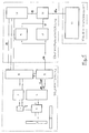
- the material 1 to be separated in FIG. 1 is produced by a separating tool 2 (e.g. a carbide saw) separately.
- the cutting tool 2 is a Gear 3 driven by a main spindle drive 4, which by a Main spindle controller module 5 is controlled.
- the feed of the Spindle feed drive 6, with which the feed of the cutting tool 2 with respect to the material to be separated 1 is caused by the feed control module 7 regulated.
- the feed control module 7 and the main spindle control module 5 are from the control and regulating device 8 of the machine tool in FIG. 1 controlled.
- the actual current I actual which flows through lines 14, 15 (or three-phase line bundle) through the main spindle drive 4, is measured in the main spindle control module 5 (as alternating current, three-phase current, etc.) and the result of this actual value measurement of the actual drive current I actual is transferred to the measuring and PD element 10 via line 16.
- the measurement of the electrical quantity in the form of the actual value of the actual drive current I actual or a value representing this current (voltage at the drive etc.) is carried out continuously.
- the setpoint value of the drive current is formed in the measurement and setpoint formation element 9 from the actual drive current (for example from the averaged actual drive current at several previous times).
- the measured actual value of the drive current and the derivation of the actual drive current value formed therefrom is determined in the measuring and PD element 10 and with the dynamic nominal value likewise derived in the measuring and nominal value formation element 9 from the actual value and / or the derivative setpoint and compared via line 17 to the summing and decoupling element 11.
- a signal from the control and Control device 8 to the feed control module 7 of the feed drive 6 Feed speed reduced to zero or in the opposite direction from the critical Danger zone of the workpiece can be positioned around the possibly prevent or avoid subsequent crash (tool breakage); alternatively or in addition, the spindle drive 5 can be stopped, for example.
- target states are these in the main spindle controller module 5 with regard to the signal release of line 16 and / or the outputs from the device 8 to the main spindle controller module 5 and the feed controller module 7 and / or the inputs of lines 19 to 8 are ignored or blocked become.
- Deviations in the form of individual broken saw blade teeth can be caused by cyclical drive actual current fluctuations are detected. These occur when one or more worn or broken teeth of the tool Pass workpiece and the following tooth the material not removed from the Separate workpiece additionally.
- critical conditions can be caused by the fact that the Flanks of one or more teeth have broken out and / or one or more Chip chambers are clogged and / or mechanical defects occur in the transmission 3 and / or the material 1 to be processed is not properly tensioned.
- the size of the detected deviations depends on the type and / or Size of the damage or malfunction.
- connection 19 led signals from the evaluation unit 12 in the main spindle controller module 8 counted within an adjustable time interval and with a predetermined target size compared. If the set target values are exceeded there is an output of the tax and according to the degree of the critical state Control device to the main spindle controller module 5 and / or that Feed controller module 7.
- control and regulation device 8 For systems without their own module for the control and regulation device 8 there is the possibility to quantize and compare (filtering) the functions to implement an electronic circuit and into the monitoring device to implement.
- the time course of the degree can be detected on the visualization system 13 critical conditions based on signals on the connection 18a optically as a function can be displayed over time.
- the visualization system 13 for example, the current flow of the main spindle drive 4 of the Machine tool shown.
- the operator of the device thus has an ongoing updated image of the current saw blade condition as well as the previous one time course of the saw blade condition.
- the relative movement between the workpiece and the tool can be (e.g. linear) back and forth movement. It can also be done by rotating the workpiece etc. be conditional.
- the elements 8 and 8 shown in FIG. 1 outside the monitoring device 5 can also be in the form of an electronic circuit in the Monitoring device can be integrated. Through this circuit, through the Machine tool, the tool, the workpiece, the machining process, the Start-up, etc., always or under certain conditions that are recorded as critical Conditions are suppressed; Messages issued by the evaluation unit Events classified as critical can be filtered out (i.e. suppressed) if they cannot be assigned to a critical condition.
Abstract
Description
Die Erfindung betrifft ein Verfahren zum Detektieren des Auftretens eines kritischen Zustandes an einem in einer Werkzeugmaschine zur Bearbeitung eines Werkstückes eingesetzten Werkzeug während des Betriebes der Werkzeugmaschine und eine Vorrichtung zur Durchführung des Verfahrens. Ein derartiger kritischer Zustand kann als eine kritische Minder-Funktionsfähigkeit eines Werkzeuges bezeichnet werden. Eine kritische Minder-Funktionsfähigkeit kann insbesondere durch Verschleißerscheinungen entstehen.The invention relates to a method for detecting the occurrence of a critical Condition on one in a machine tool for machining a workpiece used tool during the operation of the machine tool and a Device for performing the method. Such a critical condition can can be described as a critical minor functionality of a tool. A critical minor functionality can in particular be caused by Signs of wear arise.
Eine bekannte Vorrichtung der Firma Mikrotec Systemeletronik zur Werkzeugüberwachung mit der Bezeichnung "MSE 214" liefert bei der Detektion von Fehlern an Werkzeugen, insbesondere bei der Sägeblattbrucherkennung an Blocksägen innerhalb einer Rohrwalzstraße keine hinreichende Sicherheit bei der Detektion von kritischen Zuständen eines Werkzeuges. Bei dieser Vorrichtung wird mittels eines Wirbelstromsensors die Zahnhöhe von Zähnen auf einem Sageblatt vermessen und ausgewertet. Späneflug und anhaftende Späne führen zu Fehlermeldungen. Zugesetzte Spankammern werden nicht erkannt. Neu eingesetzte Sägeblätter werden von der Vorrichtung als in kritischem Zustand befindlich beurteilt, obwohl sie in einwandfreiem Zustand sind. Regenerierte Sägeblätter werden teilweise ebenfalls als fehlerhaft bewertet. Der Wirbelstromsensor, mittels welchem die Vorrichtung Fehler zu detektieren versucht und dessen Anstellmechanik unterliegen einem sehr hohen Verschleiß. Ferner sind Eich- und Lernroutinen zum Implementieren der Vorrichtung erforderlich.A known device from Mikrotec Systemeletronik for tool monitoring with the designation "MSE 214" delivers in the detection of errors Tools, especially for saw blade break detection on block saws no sufficient security in the detection of critical conditions of a tool. In this device, a Eddy current sensor measures the tooth height of teeth on a saw blade and evaluated. Chip flight and adhering chips lead to error messages. Clogged chip chambers are not recognized. Newly used saw blades judged by the device to be in critical condition, although in are in perfect condition. Regenerated saw blades are also sometimes used as incorrectly rated. The eddy current sensor, by means of which the device fails tries to detect and its adjusting mechanics are subject to a very high Wear. There are also calibration and learning routines for implementing the device required.
Weitere bekannte Ansätze betreffen Körperschallanalysen von Werkzeugen, die sich bisher in der Praxis aber nicht durchsetzen konnten. Other known approaches concern structure-borne noise analysis of tools that are but have so far not been able to implement in practice.
Ein Verfahren zur Verschleißerkennung eines elektromotorisch angetriebenen Sägeblattes ist aus der DE 41 27 191 A1 bekannt. Bei diesem bekannten Verfahren wird die über die Standzeit des Sägeblattes zunehmende Stromaufnahme des Sägeblatt-Antriebsmotors gemessen und mit einem vorgegebenen Referenz-Sollwert verglichen. Beim Erreichen einer den nicht mehr tolerierbaren Verschleiß darstellenden rechnerisch oder empirisch ermittelten Abweichung vom Referenz-Sollwert wird ein Signal zum Auswechseln des Sägeblattes gegeben. Als Referenz-Sollwert wird die aus mehreren Sägeschnitten ermittelte mittlere Stromaufnahme vorgegeben. Um Spitzenwerte der Stromaufnahme, die mit dem Verschleiß des Sägeblattes nicht in Verbindung zu bringen sind, zu eliminieren, erfolgt die Ermittlung der mittleren Stromaufnahme durch Messung der einzelnen Stromaufnahmen in den mittleren Sohnittphasen jedes gemessenen Sägeblattes.A method for detecting wear on an electric motor-driven saw blade is known from DE 41 27 191 A1. In this known method, the Service life of the saw blade increasing current consumption of the saw blade drive motor measured and compared with a predetermined reference setpoint. When you reach one the no longer tolerable wear arithmetically or empirically determined Deviation from the reference setpoint is a signal to replace the saw blade given. The mean value determined from several saw cuts is used as the reference setpoint Current consumption specified. To peak power consumption associated with wear of the saw blade cannot be connected, the determination of the average power consumption by measuring the individual power consumption in the middle The phases of each saw blade measured.
Nachteilig bei diesem bekannten Verfahren ist, daß kritische Zustände des Sägeblattes, deren Stromaufnahme noch unterhalb des Referenz-Sollwertes liegt, nicht erfaßt werden können und dieses System nicht in der Lage ist, die Detektion kritischer Zustände an Werkzeugen insbesondere hartmetallbestückter Sägeblätter zu jedem Zeitpunkt des Sägeschnittes unabhängig von der Größe des Stromeffektivwertes der Antriebseinheit vorzunehmen. A disadvantage of this known method is that critical conditions of the saw blade, whose current consumption is still below the reference setpoint cannot be recorded can and this system is unable to detect critical conditions Tools, especially carbide-tipped saw blades at any time of the day Saw cut regardless of the size of the effective current value of the drive unit to make.
Hiervon ausgehend ist die Aufgabe der Erfindung ein Verfahren zum Detektieren des Auftretens eines kritischen Zustandes eines in einer Werkzeugmaschine zur Bearbeitung eines Werkstückes eingesetzten Werkzeuges anzugeben, mit dem auch nicht den normalen Verschleiß betreffende kritische Zustände erfaßt werden können.Proceeding from this, the object of the invention is a method for detecting the Occurrence of a critical condition in a machine tool To specify machining of a workpiece used with the tool critical conditions not related to normal wear and tear cannot be detected.
Die Aufgabe wird durch die Merkmale der unabhängigen Ansprüche gelöst.The object is solved by the features of the independent claims.
Die Erfindung erlaubt einfach und kostengünstig eine instantane, zuverlässige Detektion kritischer Zustände eines Werkzeuges, insbesondere eines Sägeblattes. Dabei sind keine Lern- oder Eichroutinen notwendig. Ferner können allmählich auftretende kritische Zustände, wie Verschleißabnutzungen an Sägeblattzähnen bei Überschreitung eines Schwellwertes zuverlässig detektiert werden. Ferner erlaubt die Erfindung eine quantisierte Ausgabe des Grades des kritischen Zustandes. Dabei kann beispielsweise eine Ausgabe in Form eines Signals an eine Notsteuerung zur Abwendung der Gefahrensituation für die Werkzeugmaschine bei einem Werkzeugbruch, insbesondere Sägeblattbruch, erfolgen. Hingegen kann bei weniger kritischen Zuständen, beispielsweise geringem Verschleiß eines Sägezahnes, eine Ausgabe über auftretenden Verschleiß erfolgen.The invention allows instant, reliable, simple and inexpensive Detection of critical conditions of a tool, especially a saw blade. No learning or calibration routines are necessary. Furthermore, gradually critical conditions that occur, such as wear on saw blade teeth Reliably exceeding a threshold value can be detected. Furthermore, the Invention a quantized output of the degree of critical condition. Here can, for example, output in the form of a signal to an emergency control Averting the dangerous situation for the machine tool at one Tool breakage, especially saw blade breakage. On the other hand, less can critical conditions, such as low wear of a saw tooth, a Output about wear and tear.
Die Detektion erfolgt vorzugsweise durch Zählen von detektierten Abweichungen und Ausgabe bei Überschreitung einer vorgegebenen Zahl von Abweichungen. Die derart gezählten Abweichungen können beispielsweise durch abgenutzte oder abgebrochene Zähne eines Sägeblattes entstehen. Die Abweichungen können vor der Zählung quantisiert werden und quantisiert gezählt werden. Für Verschleiß- oder Notsteuerungs- Ausgaben können unterschiedliche Schwellwerte gesetzt werden.The detection is preferably carried out by counting detected deviations and Output when a specified number of deviations is exceeded. The so Deviations counted can be caused, for example, by worn or canceled Teeth of a saw blade arise. The deviations can be before the count be quantized and counted quantized. For wear or Emergency control outputs can have different threshold values set.
Das Verfahren ist für die Überwachung von Werkzeugen in Form von Sägeblättern entwickelt worden, welche für Hartmetallsägen, die unter rauhen Produktionsbedingungen innerhalb einer Rohrstraße arbeiten, vorgesehen sind, kann jedoch auch für andere Werkzeuge ausgebildet werden. Das Verfahren kann in einer Vorrichtung als elektronische Einrichtung und z.B. in Verbindung mit einem in einer speicherprogrammierbaren Steuerung gespeicherten Programm realisiert werden.The procedure is for monitoring tools in the form of saw blades have been developed for hard metal saws that are rough Production conditions can be provided within a pipe line but can also be trained for other tools. The process can be carried out in one Device as an electronic device and e.g. in conjunction with one in one programmable logic controller stored program can be realized.
Weitere Merkmale und Vorteile ergeben sich aus den weiteren Unteransprüchen und der nachfolgenden Beschreibung eines Ausführungsbeispiels anhand der Zeichnung. Further features and advantages result from the further subclaims and the following description of an embodiment with reference to the drawing.
Dabei zeigt:
- Fig. 1
- als Blockschaltbild eine erfindungsgemäße Vorrichtung.
- Fig. 1
- a device according to the invention as a block diagram.
Das zu trennende Material 1 in Figur 1 wird von einem Trenn- Werkzeug 2
(beispielsweise einer Hartmetallsäge) getrennt. Das Trennwerkzeug 2 wird über ein
Getriebe 3 von einem Hauptspindelantrieb 4 angetrieben, welcher von einem
Hauptspindelreglermodul 5 angesteuert wird. Der Vorschub des
Spindelvorschubantriebs 6, mit welchem der Vorschub des Trenn-Werkzeuges 2
bezüglich des zu trennenden Materials 1 bewirkt wird, wird vom Vorschubreglermodul
7 geregelt. Das Vorschubreglermodul 7 und das Hauptspindelreglermodul 5 werden
von der Steuerungs- und Regelungseinrichtung 8 der Werkzeugmaschine in Figur 1
gesteuert.The
Der Iststrom IIst, welcher durch Leitungen 14, 15 (bzw. je dreiphasige Leitungsbündel)
durch den Hauptspindelantrieb 4 fließt, wird im Hauptspindelregelmodul 5 gemessen
(als Wechselstrom, Drehstrom etc.) und das Ergebnis dieser Istwert-Messung des Ist-Antriebsstromes
IIst wird über die Leitung 16 an das Meß- und PD-Glied 10
übergeben. Die Messung der elektrischen Größe in Form des Ist-Wertes des Ist-Antriebsstroms
IIst bzw. eines diesen Strom repräsentierenden Wertes (Spannung am
Antrieb etc.) erfolgt stetig. Der Sollwert des Antriebsstromes wird in dem Meß- und
Sollwert-Bildungsglied 9 aus dem Ist-Antriebsstrom (beispielsweise aus dem
gemittelten Ist-Antriebsstrom zu mehreren vorhergehenden Zeitpunkten) gebildet. Im
Meß- und PD-Glied 10 wird der gemessene Ist-Wert des Antriebsstromes und die
daraus gebildete Ableitung des Antriebsstrom-Ist-Wertes bestimmt und mit dem
ebenfalls im Meß- und Sollwert-Bildungsglied 9 aus dem Ist-Wert abgeleiteten
dynamischen Soll-Wert und/oder dem Ableitungs-Sollwert verglichen und über die
Leitung 17 dem Summations- und Entkoppelungsglied 11 zugeführt.The actual current I actual , which flows through
Diese von den Elementen 9 und 10 detektierten und im Kompensationsglied 11
weiterverarbeiteten Signale betreffend kritische Zustande werden über die
Verbindung 18 an die Auswerteeinheit 12 und über die Leitung 18a zu einem
Visualisierungssystem 13 weitergeleitet. In der Auswerteeinheit 12 wird das über die
Verbindung 18 zugeführte Signal hinsichtlich kritischer Zustände klassifiziert und für
die nachgeschaltete Steuerungs- und Regeleinrichtung 8 bereitgestellt. Die
Auswerteeinheit 12 entscheidet über den Grad des kritischen Zustandes. Für
einstellbare Klassifizierungsstufen können Steuerbefehlsgruppen als gewünschte
Reaktion auf detektierte kritische Zustände festgelegt werden.These are detected by
Diese über die Verbindung 19 geführten Signale (bzw. Steuerbefehlsgruppen)
repräsentieren beispielsweise die Ansteuerungsbefehle für die Informationen
"Warnung", "Störung" und "Crash" (= Werkzeugbruch) für die Steuerungs- und
Regelungseinrichtung 8. Von dieser Steuerungs- und Regelungseinrichtung 8 werden
zur aktiven Schadensbegrenzung an die Antriebe über die Reglermodule 5 und/oder
7 die Signale für eine festgelegte schadensmindernde Reaktion oder Routine
übergeben.These signals (or control command groups) carried via
So kann zum Beispiel durch ein Signal von der Steuerungs- und
Regelungseinrichtung 8 an das Vorschubregelmodul 7 des Vorschubantriebes 6 die
Vorschubgeschwindigkeit auf Null reduziert bzw. in Gegenrichtung aus der kritischen
Gefahrenzone des Werkstückes positioniert werden, um dem möglicherweise
nachfolgenden Crash (Werkzeugbruch) vorzubeugen bzw. zu entgehen; alternativ
oder zusätzlich kann der Spindelantrieb 5 beispielsweise gestoppt werden.For example, a signal from the control and
Ferner kann in der Steuerungs- und Regelungseinrichtung 8 vorgesehen werden, daß
während des Hochfahrens des Antriebs 4 und/oder weiterer technologisch bedingter
Soll-Zustände im Falle von detektierten kritischen Zuständen diese im Hauptspindel-Reglermodul
5 hinsichtlich der Signalfreigabe der Leitung 16 und/oder der Ausgaben
von der Einrichtung 8 an das Hauptspindel-Reglermodul 5 und das Vorschub-Reglermodul
7 und/oder der Eingaben der Leitungen 19 an 8 ignoriert bzw. gesperrt
werden.Furthermore, it can be provided in the control and regulating
Abweichungen in Form einzelner ausgebrochener Sägeblattzähne können durch zyklische Antriebs-Ist-Strom-Schwankungen detektiert werden. Diese treten auf, wenn ein oder mehrere verschlissene oder ausgebrochene Zähne des Werkzeuges das Werkstück passieren und der nachfolgende Zahn das nicht abgetragene Material vom Werkstück zusätzlich trennen muß.Deviations in the form of individual broken saw blade teeth can be caused by cyclical drive actual current fluctuations are detected. These occur when one or more worn or broken teeth of the tool Pass workpiece and the following tooth the material not removed from the Separate workpiece additionally.
Des weiteren können kritische Zustände dadurch hervorgerufen werden, daß die
Flanken eines oder mehrerer Zähne ausgebrochen sind und/oder eine oder mehrere
Spankammern zugesetzt sind und/oder mechanische Defekte im Getriebe 3 auftreten
und/oder das zu bearbeitende Material 1 nicht ordnungsgemäß gespannt ist. Die
Größe der detektierten Abweichungen ist dabei abhängig von der Art und/oder der
Größe der Beschädigung bzw. Störung.Furthermore, critical conditions can be caused by the fact that the
Flanks of one or more teeth have broken out and / or one or more
Chip chambers are clogged and / or mechanical defects occur in the
Differenziert nach dem Grad des kritischen Zustandes werden die über die
Verbindung 19 geführten Signale aus der Auswerteeinheit 12 im Hauptspindel-Reglermodul
8 innerhalb eines einstellbaren Zeitintervalles gezählt und mit einer
vorgegebenen Soll-Größe verglichen. Bei Überschreitung der eingestellten Soll-Werte
erfolgt eine dem Grad des kritischen Zustandes entsprechende Ausgabe der Steuer- und
Regelungseinrichtung an das Hauptspindel-Reglermodul 5 und/oder das
Vorschub-Reglermodul 7.They are differentiated according to the degree of
Anhaftende Späne und/oder zugesetzte Spankammern und/oder anderweitige Ereignisse, welche einen kritischen Zustand zur Folge haben, welche innerhalb des Zeitintervalles jedoch nicht zyklisch auftreten, werden als nichtkritische Zustände bewertet und haben somit keinen Einfluß auf den technologischen Ablauf der Sägeeinrichtungs-Steuerung.Adhering chips and / or clogged chip chambers and / or other Events that result in a critical state that occur within the Time interval, however, do not occur cyclically, are considered non-critical states evaluated and thus have no influence on the technological process of the Sawing device control.
Für Anlagen ohne eigenes Modul für die Steuerungs- und Regelungseinrichtung 8
besteht die Möglichkeit, die Funkionen Quantisierung und Vergleich (Filgerung) in
einer elektronischen Schaltung zu realisieren und in die Überwachungseinrichtung zu
implementieren.For systems without their own module for the control and
Auf dem Visualisierungssystem 13 kann der zeitliche Verlauf des Grades detektierter
kritischer Zustände anhand von Signalen auf der Verbindung 18a optisch als Funktion
über der Zeit dargestellt werden. Dabei wird im Visualisierungssystem 13
beispielsweise der zeitliche Stromverlauf des Hauptspindelantriebes 4 der
Werkzeugmaschine dargestellt. Der Betreiber der Vorrichtung hat damit ein laufend
aktualisiertes Abbild des aktuellen Sägeblattzustandes sowie des bisherigen
zeitlichen Verlaufs des Sägeblattzustandes.The time course of the degree can be detected on the
Mit einer derartigen Überwachungseinrichtung können beispielsweise alle Sägeblätter an den Block- und Längensägen einer Rohrstoßbankanlage überwacht werden. With such a monitoring device, for example, all saw blades be monitored on the block and length saws of a pipe ram bench system.
Die Relativbewegung zwischen dem Werkstück und dem Werkzeug kann eine (z.B. lieare) Hin- und Her-Bewegung sein. Sie kann auch durch Rotation des Werkstücks etc. bedingt sein.The relative movement between the workpiece and the tool can be (e.g. linear) back and forth movement. It can also be done by rotating the workpiece etc. be conditional.
Die in Figur 1 außerhalb der Überwachungseinrichtung dargestellten Elemente 8 und
5 können auch in Form einer elektronischen Schaltung in der
Überwachungseinrichtung integriert sein. Durch diese Schaltung können durch die
Werkzeugmaschine, das Werkzeug, das Werkstück, den Bearbeitungsvorgang, das
Hochfahren etc. bedingte, als kritisch erfaßte Zustände immer oder unter bestimmten
Bedingungen unterdrückt werden; von der Auswerteeinheit ausgegebene Meldungen
betreffend als kritisch eingestufte Ereignisse können ausgefiltert (also unterdrückt)
werden, wenn sie keinem kritischen Zustand zugeordnet werden können.The
Claims (10)
wobei die Werkzeugmaschine mittels einer von einer Steuereinrichtung (5,8,10,11) gesteuerten Antriebseinrichtung (4) eine Relativbewegung zwischen dem Werkzeug (2) und dem Werkstück (1) erzeugt und daß der Ist-Wert (Iist) einer den die Antriebseinrichtung (4) durchfließenden Ist-Antriebsstrom repräsentierenden gemessenen elektrischen Größe in der Steuerungseinrichtung (5,10,11,8) mit einem Sollwert verglichen wird und daß bei Auftreten einer vorgebbaren Abweichung des Ist-Wertes vom Sollwert eine diesen kritischen Zustand repräsentierende Ausgabe an eine Auswerteeinheit (12) erfolgt,
dadurch gekennzeichnet,
daß aus dem zu mehreren vorhergehenden Zeitpunkten gemittelten Ist-Antriebsstrom durch Differenzieren ein abgeleiteter dynamischer Sollwert gebildet wird und mit dem gemessenen Ist-Wert des Antriebsstromes und mit der daraus gebildeten Ableitung kontinuierlich verglichen wird und zur Unterscheidung verschiedener kritischer Zustände das aufbereitete Signal klassifiziert und im Falle der Überschreitung des Grades eines kritischen Zustandes ein Steuerbefehl gebildet wird.Method for detecting the occurrence of a critical state of a tool (2) used in a machine tool (3, 4, 6, 7) for machining a workpiece (1) during operation of the machine tool,
wherein the machine tool generates a relative movement between the tool (2) and the workpiece (1) by means of a drive device (4) controlled by a control device (5,8,10,11) and that the actual value (I ist ) is one of those The measured electrical quantity representing the actual drive current flowing through the drive device (4, 10, 11, 8) in the control device (5, 10, 11, 8) is compared with a setpoint value and that if a predeterminable deviation of the actual value from the setpoint value occurs, an output to a critical value represents this Evaluation unit (12) takes place,
characterized,
that a derived dynamic setpoint is formed from the actual drive current averaged at several previous points in time and is continuously compared with the measured actual value of the drive current and with the derivative derived therefrom, and in order to differentiate between various critical states, the processed signal is classified and, in the case a control command is formed if the degree of a critical state is exceeded.
dadurch gekennzeichnet,
daß die vorgebbare Abweichung bei der eine einen kritischen Zustand repräsentierende Ausgabe erfolgt, eine Abweichung um mehr als einen vorgebbaren Sollwert der elektrischen Größe ist.Method according to claim 1,
characterized,
that the predefinable deviation in the case of an output representing a critical state is a deviation by more than a predefinable setpoint value of the electrical variable.
dadurch gekennzeichnet,
daß in einem Zähler innerhalb eines Zeitintervalls die Abweichung in Form der Häufigkeit mit oder ohne Berücksichtigung der jeweiligen Intensität und/oder Dauer der Abweichungen um mehr als einen Schwellwert gezählt wird und bei einem Maximal-Zählerstand eine Ausgabe erfolgt.Method according to claim 2,
characterized,
that the deviation in a counter within a time interval is counted in the form of the frequency with or without taking into account the respective intensity and / or duration of the deviations by more than a threshold value and an output takes place at a maximum counter reading.
dadurch gekennzeichnet,
daß das Vergleichen des Ist -Wertes mit dem Sollwert stetig erfolgt. Method according to one of the preceding claims,
characterized,
that the comparison of the actual value with the setpoint takes place continuously.
dadurch gekennzeichnet,
daß das Vergleichen durch Differenzieren von Ist-Werten und Vergleichen differenzierter Ist-Werte mit den dynamisch vorgegebenen Soll-Werten erfolgt.Method according to one of the preceding claims,
characterized,
that the comparison is carried out by differentiating actual values and comparing differentiated actual values with the dynamically predetermined target values.
dadurch gekennzeichnet,
daß aufgrund der Abweichungen von einer Auswerteeinheit die Art des kritischen Zustandes bestimmt wird und daß die Ausgabe die Art des kritischen Zustandes angibt.Method according to one of the preceding claims,
characterized,
that the type of critical state is determined on the basis of the deviations from an evaluation unit and that the output indicates the type of critical state.
dadurch gekennzeichnet,
daß bei Detektion einer Abweichung in Form eines Werkzeugbruches, insbesondere eines Sägeblattbruches und/oder einer zugesetzten Spankammer und/oder eines mechanischen Defekts und/oder eines sonstigen Ereignisses, welches einen kritischen Zustand zur Folge hat, eine Ausgabe in Form eines Ausgangssignals an eine Steuerungs- und Regelungseinrichtung erfolgt, die zur sofortigen Aktivierung des Schnittabbruches und/oder in Folge zur Stilisetzung der Antriebsmaschine führt.Method according to one of the preceding claims,
characterized,
that upon detection of a deviation in the form of a tool break, in particular a saw blade break and / or an added chip chamber and / or a mechanical defect and / or another event that results in a critical condition, an output in the form of an output signal to a control and control device takes place, which leads to the immediate activation of the cut-off and / or consequently to the stylization of the drive machine.
dadurch gekennzeichnet,
daß bei die Arbeit des Werkzeuges noch erlaubenden kritischen Zuständen, insbesondere bei Sägezahnabbruch oder Sägezahnabnutzungen, nur die Art des kritischen Zustandes akustisch und/oder optisch als Ausgabe angezeigt wird.Method according to one of the preceding claims,
characterized,
that in critical conditions still permitting the work of the tool, in particular in the case of saw tooth breakage or saw tooth wear, only the type of the critical condition is indicated acoustically and / or optically as an output.
zum Detektieren des Auftretens eines kritischen Zustandes an einem in einer Werkzeugmaschine zur Bearbeitung eines Werkzeuges eingesetzten Werkzeug während des Betriebes der Werkzeugmaschine,
for detecting the occurrence of a critical condition on a tool used in a machine tool for machining a tool during the operation of the machine tool,
dadurch gekennzeichnet,
daß die Ausgänge einen den Grad des kritischen Zustandes quantisiert wiedergebenden Ausgang zu einem Visualisierungssystem (13) umfassen.Device according to claim 9,
characterized,
that the outputs comprise an output to a visualization system (13) which quantizes the degree of the critical state.
Applications Claiming Priority (2)
| Application Number | Priority Date | Filing Date | Title |
|---|---|---|---|
| DE19830035A DE19830035B4 (en) | 1998-06-26 | 1998-06-26 | Method and device for detecting the occurrence of a critical condition of a tool, in particular a saw blade |
| DE19830035 | 1998-06-26 |
Publications (2)
| Publication Number | Publication Date |
|---|---|
| EP0969340A1 true EP0969340A1 (en) | 2000-01-05 |
| EP0969340B1 EP0969340B1 (en) | 2004-11-24 |
Family
ID=7873055
Family Applications (1)
| Application Number | Title | Priority Date | Filing Date |
|---|---|---|---|
| EP99250205A Expired - Lifetime EP0969340B1 (en) | 1998-06-26 | 1999-06-23 | Process and device for the detection of a critical state of a tool , particulary of a saw blade |
Country Status (3)
| Country | Link |
|---|---|
| EP (1) | EP0969340B1 (en) |
| AT (1) | ATE283509T1 (en) |
| DE (2) | DE19830035B4 (en) |
Cited By (3)
| Publication number | Priority date | Publication date | Assignee | Title |
|---|---|---|---|---|
| FR2828424A1 (en) * | 2001-08-07 | 2003-02-14 | Sarl Digital Way | Monitoring of a machine tool for wear or breakage using a monitoring device that can measure active power or active currents absorbed by the operating motor as well as monitoring tool wear or breakage against a reference curve |
| WO2023285369A1 (en) | 2021-07-15 | 2023-01-19 | Framag Industrieanlagenbau Gmbh | Method and device for controlling the feed rate of circular saw blades |
| CN116197458A (en) * | 2023-01-12 | 2023-06-02 | 承龙科技(嘉兴)有限公司 | Edge chamfering device and process for fastening nut |
Families Citing this family (3)
| Publication number | Priority date | Publication date | Assignee | Title |
|---|---|---|---|---|
| DE10206615B4 (en) * | 2002-02-15 | 2008-03-27 | Lucas Automotive Gmbh | Procedure for detecting tooth eruption on circular saw blades and for emergency shutdown of the circular saw and circular saw, which is monitored according to these methods |
| CN105116853B (en) * | 2015-07-21 | 2018-03-02 | 长沙长泰机器人有限公司 | The quick control device and quick control method that casting is cleared up automatically |
| DE102016209746A1 (en) * | 2016-06-03 | 2017-12-07 | Robert Bosch Gmbh | Method for monitoring the functionality of a working device and implement |
Citations (4)
| Publication number | Priority date | Publication date | Assignee | Title |
|---|---|---|---|---|
| US4978909A (en) * | 1988-11-14 | 1990-12-18 | Martin Marietta Energy Systems, Inc. | Demodulation circuit for AC motor current spectral analysis |
| DE4127191A1 (en) | 1991-08-13 | 1993-02-18 | Mannesmann Ag | Wear determination method for cutting blades in automated processing - monitoring drive motor current and comparing with empirically-determined value for worn blade |
| US5243533A (en) * | 1990-03-26 | 1993-09-07 | Ntn Corporation | Tool abnormality detecting device |
| US5523701A (en) * | 1994-06-21 | 1996-06-04 | Martin Marietta Energy Systems, Inc. | Method and apparatus for monitoring machine performance |
-
1998
- 1998-06-26 DE DE19830035A patent/DE19830035B4/en not_active Expired - Fee Related
-
1999
- 1999-06-23 EP EP99250205A patent/EP0969340B1/en not_active Expired - Lifetime
- 1999-06-23 DE DE59911123T patent/DE59911123D1/en not_active Expired - Fee Related
- 1999-06-23 AT AT99250205T patent/ATE283509T1/en not_active IP Right Cessation
Patent Citations (4)
| Publication number | Priority date | Publication date | Assignee | Title |
|---|---|---|---|---|
| US4978909A (en) * | 1988-11-14 | 1990-12-18 | Martin Marietta Energy Systems, Inc. | Demodulation circuit for AC motor current spectral analysis |
| US5243533A (en) * | 1990-03-26 | 1993-09-07 | Ntn Corporation | Tool abnormality detecting device |
| DE4127191A1 (en) | 1991-08-13 | 1993-02-18 | Mannesmann Ag | Wear determination method for cutting blades in automated processing - monitoring drive motor current and comparing with empirically-determined value for worn blade |
| US5523701A (en) * | 1994-06-21 | 1996-06-04 | Martin Marietta Energy Systems, Inc. | Method and apparatus for monitoring machine performance |
Non-Patent Citations (1)
| Title |
|---|
| SPUR G ET AL: "SENSORLOSE WERKZEUGUEBERWACHUNG FUER DIE CNC-DREHBEARBEITUNG SENSORLESS TOOL MONITORING FOR CNC LATHE OPERATION", ZWF ZEITSCHRIFT FUR WIRTSCHAFTLICHE FERTIGUNG UND AUTOMATISIERUNG, vol. 88, no. 4, 1 April 1993 (1993-04-01), pages 173 - 175, XP000360368, ISSN: 0947-0085 * |
Cited By (6)
| Publication number | Priority date | Publication date | Assignee | Title |
|---|---|---|---|---|
| FR2828424A1 (en) * | 2001-08-07 | 2003-02-14 | Sarl Digital Way | Monitoring of a machine tool for wear or breakage using a monitoring device that can measure active power or active currents absorbed by the operating motor as well as monitoring tool wear or breakage against a reference curve |
| WO2003019301A2 (en) * | 2001-08-07 | 2003-03-06 | Digital Way | Tool wear and/or breakage control device for a machine tool |
| WO2003019301A3 (en) * | 2001-08-07 | 2003-09-25 | Digital Way | Tool wear and/or breakage control device for a machine tool |
| WO2023285369A1 (en) | 2021-07-15 | 2023-01-19 | Framag Industrieanlagenbau Gmbh | Method and device for controlling the feed rate of circular saw blades |
| CN116197458A (en) * | 2023-01-12 | 2023-06-02 | 承龙科技(嘉兴)有限公司 | Edge chamfering device and process for fastening nut |
| CN116197458B (en) * | 2023-01-12 | 2024-04-30 | 承龙科技(嘉兴)有限公司 | Edge chamfering device and process for fastening nut |
Also Published As
| Publication number | Publication date |
|---|---|
| DE19830035A1 (en) | 2000-01-13 |
| DE59911123D1 (en) | 2004-12-30 |
| ATE283509T1 (en) | 2004-12-15 |
| EP0969340B1 (en) | 2004-11-24 |
| DE19830035B4 (en) | 2005-03-03 |
Similar Documents
| Publication | Publication Date | Title |
|---|---|---|
| DE2328876A1 (en) | METHOD AND DEVICE FOR MONITORING THE CONDITION OF A CUTTER HEAD ON A MACHINE FOR MANUFACTURING SPIRAL BEVEL WHEELS | |
| DE102019001972A1 (en) | Fault detection device | |
| DE3411113A1 (en) | METHOD FOR DETERMINING TOOL WEAR | |
| DE60117049T2 (en) | MACHINE STATE MONITORING DEVICE WITH CONTROL DEVICE | |
| EP0969340B1 (en) | Process and device for the detection of a critical state of a tool , particulary of a saw blade | |
| EP4244011A2 (en) | Method for grinding a toothing or a profile of a workpiece | |
| DE3415305A1 (en) | METHOD AND ARRANGEMENT FOR MONITORING THE MACHINING CONDITIONS ON A MACHINE TOOL | |
| DE3741973C2 (en) | ||
| DE3902840C2 (en) | ||
| DE102020107861B4 (en) | System for managing tool change times | |
| DE102021209846A1 (en) | Monitoring procedure for a flying crank shears process for plate billets | |
| DE102020205088A1 (en) | Method and evaluation system for monitoring tool wear on tool components in machining production plants | |
| DE112021003871T5 (en) | ANOMALITY DETECTION DEVICE | |
| DE3311861C2 (en) | ||
| DE112020005149T5 (en) | Process and system for monitoring the processing status of a working machine | |
| DE2251333C3 (en) | Device for monitoring the machining conditions on a lathe | |
| DE19722937A1 (en) | Control system and method for regulating processing speeds in woodworking | |
| DE102014208854B4 (en) | Method for checking a machine tool and a corresponding machine tool | |
| DE10206615B4 (en) | Procedure for detecting tooth eruption on circular saw blades and for emergency shutdown of the circular saw and circular saw, which is monitored according to these methods | |
| DE3511140A1 (en) | Method and apparatus for monitoring cutting tools, in particular for monitoring for drill fracture | |
| EP0215268A1 (en) | Method of valuating and device for detecting the quality of cut during the cutting of materials | |
| EP2347846A1 (en) | Circular saw | |
| DE2437256A1 (en) | CIRCUIT ARRANGEMENT FOR TOOL BREAKAGE CONTROL | |
| WO2021185820A1 (en) | Method for determining a wear condition of a tool, and device therefor | |
| WO2023036828A1 (en) | Method for determining the wear state of a tool, and device for said method |
Legal Events
| Date | Code | Title | Description |
|---|---|---|---|
| PUAI | Public reference made under article 153(3) epc to a published international application that has entered the european phase |
Free format text: ORIGINAL CODE: 0009012 |
|
| AK | Designated contracting states |
Kind code of ref document: A1 Designated state(s): AT BE CH CY DE DK ES FI FR GB GR IE IT LI LU MC NL PT SE |
|
| AX | Request for extension of the european patent |
Free format text: AL;LT;LV;MK;RO;SI |
|
| 17P | Request for examination filed |
Effective date: 20000628 |
|
| AKX | Designation fees paid |
Free format text: AT BE CH CY DE DK ES FI FR GB GR IE IT LI LU MC NL PT SE |
|
| 17Q | First examination report despatched |
Effective date: 20030227 |
|
| RAP1 | Party data changed (applicant data changed or rights of an application transferred) |
Owner name: V & M DEUTSCHLAND GMBH |
|
| GRAP | Despatch of communication of intention to grant a patent |
Free format text: ORIGINAL CODE: EPIDOSNIGR1 |
|
| GRAS | Grant fee paid |
Free format text: ORIGINAL CODE: EPIDOSNIGR3 |
|
| RBV | Designated contracting states (corrected) |
Designated state(s): AT DE |
|
| GRAA | (expected) grant |
Free format text: ORIGINAL CODE: 0009210 |
|
| AK | Designated contracting states |
Kind code of ref document: B1 Designated state(s): AT DE |
|
| REF | Corresponds to: |
Ref document number: 59911123 Country of ref document: DE Date of ref document: 20041230 Kind code of ref document: P |
|
| REG | Reference to a national code |
Ref country code: IE Ref legal event code: FG4D Free format text: GERMAN |
|
| PGFP | Annual fee paid to national office [announced via postgrant information from national office to epo] |
Ref country code: DE Payment date: 20050613 Year of fee payment: 7 |
|
| PGFP | Annual fee paid to national office [announced via postgrant information from national office to epo] |
Ref country code: AT Payment date: 20050615 Year of fee payment: 7 |
|
| REG | Reference to a national code |
Ref country code: IE Ref legal event code: FD4D |
|
| PLBE | No opposition filed within time limit |
Free format text: ORIGINAL CODE: 0009261 |
|
| STAA | Information on the status of an ep patent application or granted ep patent |
Free format text: STATUS: NO OPPOSITION FILED WITHIN TIME LIMIT |
|
| 26N | No opposition filed |
Effective date: 20050825 |
|
| PG25 | Lapsed in a contracting state [announced via postgrant information from national office to epo] |
Ref country code: AT Free format text: LAPSE BECAUSE OF NON-PAYMENT OF DUE FEES Effective date: 20060623 |
|
| PG25 | Lapsed in a contracting state [announced via postgrant information from national office to epo] |
Ref country code: DE Free format text: LAPSE BECAUSE OF NON-PAYMENT OF DUE FEES Effective date: 20070103 |