EP0968878A2 - Device for the sealing of compartments in tanks for the transport of hydrocarbons - Google Patents
Device for the sealing of compartments in tanks for the transport of hydrocarbons Download PDFInfo
- Publication number
- EP0968878A2 EP0968878A2 EP99201675A EP99201675A EP0968878A2 EP 0968878 A2 EP0968878 A2 EP 0968878A2 EP 99201675 A EP99201675 A EP 99201675A EP 99201675 A EP99201675 A EP 99201675A EP 0968878 A2 EP0968878 A2 EP 0968878A2
- Authority
- EP
- European Patent Office
- Prior art keywords
- compartments
- sealing
- tanks
- sensors
- hydrocarbons
- Prior art date
- Legal status (The legal status is an assumption and is not a legal conclusion. Google has not performed a legal analysis and makes no representation as to the accuracy of the status listed.)
- Withdrawn
Links
Images


Classifications
-
- B—PERFORMING OPERATIONS; TRANSPORTING
- B67—OPENING, CLOSING OR CLEANING BOTTLES, JARS OR SIMILAR CONTAINERS; LIQUID HANDLING
- B67D—DISPENSING, DELIVERING OR TRANSFERRING LIQUIDS, NOT OTHERWISE PROVIDED FOR
- B67D7/00—Apparatus or devices for transferring liquids from bulk storage containers or reservoirs into vehicles or into portable containers, e.g. for retail sale purposes
- B67D7/06—Details or accessories
- B67D7/32—Arrangements of safety or warning devices; Means for preventing unauthorised delivery of liquid
-
- B—PERFORMING OPERATIONS; TRANSPORTING
- B60—VEHICLES IN GENERAL
- B60P—VEHICLES ADAPTED FOR LOAD TRANSPORTATION OR TO TRANSPORT, TO CARRY, OR TO COMPRISE SPECIAL LOADS OR OBJECTS
- B60P3/00—Vehicles adapted to transport, to carry or to comprise special loads or objects
- B60P3/22—Tank vehicles
- B60P3/224—Tank vehicles comprising auxiliary devices, e.g. for unloading or level indicating
- B60P3/2265—Arrangements for hoses, tubes, or reels
-
- B—PERFORMING OPERATIONS; TRANSPORTING
- B60—VEHICLES IN GENERAL
- B60P—VEHICLES ADAPTED FOR LOAD TRANSPORTATION OR TO TRANSPORT, TO CARRY, OR TO COMPRISE SPECIAL LOADS OR OBJECTS
- B60P3/00—Vehicles adapted to transport, to carry or to comprise special loads or objects
- B60P3/22—Tank vehicles
- B60P3/224—Tank vehicles comprising auxiliary devices, e.g. for unloading or level indicating
- B60P3/229—Anti-theft means
-
- B—PERFORMING OPERATIONS; TRANSPORTING
- B67—OPENING, CLOSING OR CLEANING BOTTLES, JARS OR SIMILAR CONTAINERS; LIQUID HANDLING
- B67D—DISPENSING, DELIVERING OR TRANSFERRING LIQUIDS, NOT OTHERWISE PROVIDED FOR
- B67D7/00—Apparatus or devices for transferring liquids from bulk storage containers or reservoirs into vehicles or into portable containers, e.g. for retail sale purposes
- B67D7/06—Details or accessories
- B67D7/32—Arrangements of safety or warning devices; Means for preventing unauthorised delivery of liquid
- B67D7/34—Means for preventing unauthorised delivery of liquid
- B67D7/344—Means for preventing unauthorised delivery of liquid by checking a correct coupling or coded information
- B67D7/346—Means for preventing unauthorised delivery of liquid by checking a correct coupling or coded information by reading a code
Definitions
- the present invention refers to a device for the sealing of compartments in tanks for the transport of hydrocarbons, provided in order to make it possible to establish a seal in the outside valves of the charge and discharge pipes of the compartments, electronically and automatically. This implies noteworthy relevant and advantageous characteristics with regard to the means and devices used at present.
- the device for the sealing of compartments in tanks for the transport of hydrocarbons that constitutes the object of the invention, has some contact sensors that establish the sealing, sensors which are placed in the dust caps of the standard API (American Petroleum Institute) couplings for the charge and discharge of the tank with some characteristics stipulated by this specific institute for the transport of petroleum.
- API American Petroleum Institute
- the sensors are mounted in respective perforations of said dust caps, making contact with the inside stopper of the coupling, being kept in their position by the cams that keep the dust caps fastened to the coupling, in such a way that in said connection the leak tightness of the coupling with the cap is established.
- the leak tightness is re-established upon placing O-ring seals in the sensor. This sensor is of intrinsic safety upon being in possible contact with the fuel.
- the establishment of the sealing is done by means of an electronic signal taken from the connection base of the high level cut-off sensors for avoiding overfilling of the compartments of the tanks, taking advantage of the fact that this connecting operation is obligatorily done one-to-one with the charging process, this being reflected on a sealing indicator light of the cited compartment, on the control panel, or by an electronic signal taken from the low level sensors located in the bottom of each compartment that indicate that the compartment is empty, as a necessary condition to carry out the sealing, taking advantage of the fact that this empty state is obligatory as a state prior to the charging process, which is also reflected by a sealing indicator light of the cited compartment on the control panel, or else the combination of both signals as necessary conditions in order to proceed with the sealing.
- the breaking of the seal is done when the dust cap is removed in order to be able to connect the discharge hose itself, this condition being reflected by the light for indicating the sealing of the compartment.
- the functioning is done by means of a programmable logical automaton.
- the philosophy of this system is not to prevent the breaking of the seal of the compartment, but rather to leave proof of this incident, in such a way that the information cannot be deleted and thus the consignee will be aware that manipulation has taken place before the destination has been reached.
- the device acts automatically and completely autonomously in accordance with the charging and discharging processes, supplying its information to the operators, but inviolable to any outside manipulation, leaving proof of any manipulation of the product.
- Figure 1 is a longitudinal sectional view that shows an exploded view of an API coupling and the dust cap carrying the sensor that defines the device for the sealing of compartments in tanks for the transport of hydrocarbons, in accordance with the invention.
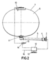
- Figure 2 is a cross section view of the tank in whose bottom the piping ended in the API coupling with the dust cap is located, also including the high level feed connection base installation and the control that the automaton carries out.
- Figure 3 shows a practical application of the different components of the device of the invention, to a typical cistern tank with various compartments.
- the device for the sealing of compartments in tanks for the transport of hydrocarbons consists of providing for the placement of some contact sensors, generally referred to as number (1) located in a perforation existing in the respective dust cap (2) that is blocked by means of the cams (3) in the free end of the API coupling (4) of the charge and discharge pipes (5) of the respective compartment (6) of the tank (7).
- the sensor (1) establishes contact with the inside stopper (8) of the coupling (4), aided by the spring (9).
- the “sealing" condition is established, by means of an electronic signal taken from the connection base of the high level limiting sensors (10), as shown in figures 2 and 3.
- the pipings (5) that end in the API couplings (4) are connected to the bottom valves (11) of the respective compartments (6).
- the sensors (1) of the different dust caps (2) are controlled from the automaton (12), this being reflected on the control panel (13).
- Reference (14) designates the high level feed connection base and reference (15) designates the connection plug in the loading platform.
- Reference (16) designates the feed cable from the battery.
Landscapes
- Engineering & Computer Science (AREA)
- Mechanical Engineering (AREA)
- Health & Medical Sciences (AREA)
- Public Health (AREA)
- Transportation (AREA)
- Loading And Unloading Of Fuel Tanks Or Ships (AREA)
- Refuse Collection And Transfer (AREA)
Abstract
Description
- As expressed in the title of this specification, the present invention refers to a device for the sealing of compartments in tanks for the transport of hydrocarbons, provided in order to make it possible to establish a seal in the outside valves of the charge and discharge pipes of the compartments, electronically and automatically. This implies noteworthy relevant and advantageous characteristics with regard to the means and devices used at present.
- Nowadays, in the marketing of petroleum products manual mechanical seals are established with lead seals that must be broken in order to operate the valves that allow the discharge of the tank. The sealing process is done after the charging process, in the supply installations, a task which is done by the staff of the supplier, in order to justify to the consignee that the product has not been manipulated until it has reached the consignee who is the one that has to break the seal. Therefore, nowadays the sealing is done mechanically and manually.
- In broad outline, the device for the sealing of compartments in tanks for the transport of hydrocarbons, that constitutes the object of the invention, has some contact sensors that establish the sealing, sensors which are placed in the dust caps of the standard API (American Petroleum Institute) couplings for the charge and discharge of the tank with some characteristics stipulated by this specific institute for the transport of petroleum.
- The sensors are mounted in respective perforations of said dust caps, making contact with the inside stopper of the coupling, being kept in their position by the cams that keep the dust caps fastened to the coupling, in such a way that in said connection the leak tightness of the coupling with the cap is established. In spite of the perforation that is made in order to install the sensor, the leak tightness is re-established upon placing O-ring seals in the sensor. This sensor is of intrinsic safety upon being in possible contact with the fuel.
- The establishment of the sealing is done by means of an electronic signal taken from the connection base of the high level cut-off sensors for avoiding overfilling of the compartments of the tanks, taking advantage of the fact that this connecting operation is obligatorily done one-to-one with the charging process, this being reflected on a sealing indicator light of the cited compartment, on the control panel, or by an electronic signal taken from the low level sensors located in the bottom of each compartment that indicate that the compartment is empty, as a necessary condition to carry out the sealing, taking advantage of the fact that this empty state is obligatory as a state prior to the charging process, which is also reflected by a sealing indicator light of the cited compartment on the control panel, or else the combination of both signals as necessary conditions in order to proceed with the sealing.
- The breaking of the seal is done when the dust cap is removed in order to be able to connect the discharge hose itself, this condition being reflected by the light for indicating the sealing of the compartment.
- The functioning is done by means of a programmable logical automaton. The philosophy of this system is not to prevent the breaking of the seal of the compartment, but rather to leave proof of this incident, in such a way that the information cannot be deleted and thus the consignee will be aware that manipulation has taken place before the destination has been reached.
- The device acts automatically and completely autonomously in accordance with the charging and discharging processes, supplying its information to the operators, but inviolable to any outside manipulation, leaving proof of any manipulation of the product.
- In order to complete the description that is going to be made hereinafter and to provide a better understanding of the characteristics of the invention, a set of drawings on the basis of whose figures the innovations and advantages of the device object of the invention will be more easily understood, is attached to the present specification.
- Figure 1 is a longitudinal sectional view that shows an exploded view of an API coupling and the dust cap carrying the sensor that defines the device for the sealing of compartments in tanks for the transport of hydrocarbons, in accordance with the invention.
- Figure 2 is a cross section view of the tank in whose bottom the piping ended in the API coupling with the dust cap is located, also including the high level feed connection base installation and the control that the automaton carries out.
- Figure 3 shows a practical application of the different components of the device of the invention, to a typical cistern tank with various compartments.
- Making reference to the numbering used in the figures, we can see how the device for the sealing of compartments in tanks for the transport of hydrocarbons, that the invention proposes, consists of providing for the placement of some contact sensors, generally referred to as number (1) located in a perforation existing in the respective dust cap (2) that is blocked by means of the cams (3) in the free end of the API coupling (4) of the charge and discharge pipes (5) of the respective compartment (6) of the tank (7). The sensor (1) establishes contact with the inside stopper (8) of the coupling (4), aided by the spring (9).
- The "sealing" condition is established, by means of an electronic signal taken from the connection base of the high level limiting sensors (10), as shown in figures 2 and 3.
- The pipings (5) that end in the API couplings (4) are connected to the bottom valves (11) of the respective compartments (6). The sensors (1) of the different dust caps (2) (see figure 3) are controlled from the automaton (12), this being reflected on the control panel (13).
- Reference (14) designates the high level feed connection base and reference (15) designates the connection plug in the loading platform. Reference (16) designates the feed cable from the battery.
- When the operator disconnects the caps (2) from the different API couplings (4) linked to the respective compartments (6) of the tank (7), in order to connect the discharge hoses, the breaking of the seal is reflected on the control panel (13), being inviolable to any outside manipulation since the information cannot be deleted, thus confirming the manipulation of the product, as we have indicated above.
Claims (5)
- Device for the sealing of compartments in tanks for the transport of hydrocarbons, each one of the compartments being connected by its bottom valves to respective pipes ending in standard couplings that are closed by a cap, characterized in that the different couplings (4) for the charge and discharge of the tank (7), of each one of the compartments (6) some contact sensors (1) that pass through the dust caps (2) of the couplings and that establish the sealing upon being pressed by the inside stopper of the respective coupling, generating an electronic signal that is stored in an automaton and that cannot be deleted, being reflected in a light for indicating sealing of the corresponding compartment (6), on the control panel (13); all so that the breaking of the seal is done by removing the dust cap (2) in order to connect a discharge hose, the electronic signal generated due to the lack of contact of the sensors (1) corresponding to the compartments (6) being kept in the automaton in such a way that the information cannot be deleted and is shown on the control panel (13).
- Device for the sealing of compartments in tanks for the transport of hydrocarbons, according to claim 1, characterized in that the electronic signal is taken from the connection base (14) of the high level cut-off sensors (10) for preventing the overfilling of the cited compartments (6), taking advantage of the fact that this connecting operation is obligatorily done one-to-one with the charging process.
- Device for the sealing of compartments in tanks for the transport of hydrocarbons, according to claim 1, characterized in that the electronic signal is taken from low level sensors installed in the bottom of each compartment in order to indicate that the same is empty, taking advantage of the fact that that this empty state is obligatory as prior to the charging process.
- Device for the sealing of compartments in tanks for the transport of hydrocarbons, according to the above claims, characterized in that the electronic signal is taken combining copulatively the signal of the connection base of the high level sensors of the compartments together with the signal coming from the low level sensors indicating that the compartment to be sealed is empty.
- Device for the sealing of compartments in tanks for the transport of hydrocarbons, according to the above claims, characterized in that the control is done by means of a programmable logical automaton that allows the storage and control of the information received from the sensors (10), the information being inviolable to any outside manipulation.
Applications Claiming Priority (2)
| Application Number | Priority Date | Filing Date | Title |
|---|---|---|---|
| ES9801405U | 1998-05-29 | ||
| ES9801405 | 1998-05-29 |
Publications (2)
| Publication Number | Publication Date |
|---|---|
| EP0968878A2 true EP0968878A2 (en) | 2000-01-05 |
| EP0968878A3 EP0968878A3 (en) | 2000-02-23 |
Family
ID=8304384
Family Applications (1)
| Application Number | Title | Priority Date | Filing Date |
|---|---|---|---|
| EP99201675A Withdrawn EP0968878A3 (en) | 1998-05-29 | 1999-05-27 | Device for the sealing of compartments in tanks for the transport of hydrocarbons |
Country Status (4)
| Country | Link |
|---|---|
| EP (1) | EP0968878A3 (en) |
| FR (1) | FR2779132B1 (en) |
| MA (1) | MA24870A1 (en) |
| PT (1) | PT102304B (en) |
Cited By (1)
| Publication number | Priority date | Publication date | Assignee | Title |
|---|---|---|---|---|
| EP1486401A1 (en) * | 2003-06-10 | 2004-12-15 | Deere & Company | Frame |
Families Citing this family (1)
| Publication number | Priority date | Publication date | Assignee | Title |
|---|---|---|---|---|
| DE102011116575A1 (en) * | 2011-10-21 | 2013-04-25 | Saeta Gmbh & Co. Kg | Plant for dispensing liquid from a tank truck |
Citations (5)
| Publication number | Priority date | Publication date | Assignee | Title |
|---|---|---|---|---|
| US1860288A (en) * | 1930-08-28 | 1932-05-24 | Ross W Hyndman | Oil tank faucet bar lock |
| US3123175A (en) * | 1964-03-03 | Switch | ||
| DE3229710A1 (en) * | 1982-01-25 | 1983-08-04 | Emil Günter 5439 Bad Marienberg Theis | Theft protection for liquid tanks |
| FR2601768A1 (en) * | 1986-07-16 | 1988-01-22 | Shell France | System for monitoring the state of filling and discharging of a tank compartment in a liquid product transport vehicle, in particular a petroleum product transport vehicle |
| GB2318567A (en) * | 1996-10-22 | 1998-04-29 | Drum Eng Co Ltd | Fuel delivery control apparatus |
-
1999
- 1999-05-27 MA MA25600A patent/MA24870A1/en unknown
- 1999-05-27 EP EP99201675A patent/EP0968878A3/en not_active Withdrawn
- 1999-05-28 PT PT10230499A patent/PT102304B/en not_active IP Right Cessation
- 1999-05-28 FR FR9906778A patent/FR2779132B1/en not_active Expired - Fee Related
Patent Citations (5)
| Publication number | Priority date | Publication date | Assignee | Title |
|---|---|---|---|---|
| US3123175A (en) * | 1964-03-03 | Switch | ||
| US1860288A (en) * | 1930-08-28 | 1932-05-24 | Ross W Hyndman | Oil tank faucet bar lock |
| DE3229710A1 (en) * | 1982-01-25 | 1983-08-04 | Emil Günter 5439 Bad Marienberg Theis | Theft protection for liquid tanks |
| FR2601768A1 (en) * | 1986-07-16 | 1988-01-22 | Shell France | System for monitoring the state of filling and discharging of a tank compartment in a liquid product transport vehicle, in particular a petroleum product transport vehicle |
| GB2318567A (en) * | 1996-10-22 | 1998-04-29 | Drum Eng Co Ltd | Fuel delivery control apparatus |
Cited By (2)
| Publication number | Priority date | Publication date | Assignee | Title |
|---|---|---|---|---|
| EP1486401A1 (en) * | 2003-06-10 | 2004-12-15 | Deere & Company | Frame |
| US6942163B2 (en) | 2003-06-10 | 2005-09-13 | Deere & Company | Implement with plumbing lines through a main frame tube |
Also Published As
| Publication number | Publication date |
|---|---|
| FR2779132B1 (en) | 2000-12-08 |
| MA24870A1 (en) | 1999-12-31 |
| PT102304A (en) | 1999-12-31 |
| EP0968878A3 (en) | 2000-02-23 |
| FR2779132A1 (en) | 1999-12-03 |
| PT102304B (en) | 2003-10-31 |
Similar Documents
| Publication | Publication Date | Title |
|---|---|---|
| US8051882B2 (en) | Tanker truck monitoring system | |
| CN101208257A (en) | Vacuum-actuated shear valve device, system, and method, particularly for use in service station environments | |
| US7938151B2 (en) | Safety device to prevent overfilling | |
| US3908718A (en) | Vapour recovery systems of liquid fuel storage | |
| NO853486L (en) | WIRING DEVICES. | |
| US4936705A (en) | Reservoir for an underground tank | |
| US3983913A (en) | Vapor recovery and vent signal system | |
| EP2884437B1 (en) | Method, control unit and computer program product for controlling a product loading state of at least one compartment in a tank vehicle | |
| US5711456A (en) | Above ground fuel transfer module | |
| GB2293658A (en) | Unloading system for a tanker | |
| EP0968878A2 (en) | Device for the sealing of compartments in tanks for the transport of hydrocarbons | |
| US5160054A (en) | Tamper evident vent system for containers | |
| US5955657A (en) | Pipe layout with opposing incline | |
| US5123441A (en) | Apparatus for fluid transfer | |
| EP0107954B1 (en) | Hydraulic fluid containers and reservoirs | |
| US4121614A (en) | Valve guard for bottom operated tank car valve | |
| CN111252723B (en) | Oil depot and oil refinery oil loading and unloading management system | |
| US3881510A (en) | Valved vapor seal for underground tanks | |
| MXPA00003743A (en) | Method and apparatus for draining connecting pipes between tanks. | |
| US20060011260A1 (en) | Liquid replenishment system | |
| KR100503870B1 (en) | Open and closing device of a bottom valve and a vapor valve in tank truck | |
| US4137937A (en) | Adapter for bottom operable tank car valve | |
| JP3329190B2 (en) | Tank lorry | |
| CN206975441U (en) | Vehicle launch lead sealing monitoring system | |
| KR101096560B1 (en) | Moniterirng system for gas filling and valve connection |
Legal Events
| Date | Code | Title | Description |
|---|---|---|---|
| PUAI | Public reference made under article 153(3) epc to a published international application that has entered the european phase |
Free format text: ORIGINAL CODE: 0009012 |
|
| AK | Designated contracting states |
Kind code of ref document: A2 Designated state(s): GB GR IE IT LU MC NL SE |
|
| AX | Request for extension of the european patent |
Free format text: AL;LT;LV;MK;RO;SI |
|
| PUAL | Search report despatched |
Free format text: ORIGINAL CODE: 0009013 |
|
| AK | Designated contracting states |
Kind code of ref document: A3 Designated state(s): AT BE CH CY DE DK ES FI FR GB GR IE IT LI LU MC NL PT SE |
|
| AX | Request for extension of the european patent |
Free format text: AL;LT;LV;MK;RO;SI |
|
| RIC1 | Information provided on ipc code assigned before grant |
Free format text: 7B 60P 3/20 A, 7B 60P 3/22 B |
|
| 17P | Request for examination filed |
Effective date: 20000810 |
|
| AKX | Designation fees paid |
Free format text: GB GR IE IT LU MC NL SE |
|
| REG | Reference to a national code |
Ref country code: DE Ref legal event code: 8566 |
|
| 17Q | First examination report despatched |
Effective date: 20070404 |
|
| STAA | Information on the status of an ep patent application or granted ep patent |
Free format text: STATUS: THE APPLICATION IS DEEMED TO BE WITHDRAWN |
|
| 18D | Application deemed to be withdrawn |
Effective date: 20070815 |