EP0967744A1 - Method and apparatus for determining characteristics of components of a communication channel under load - Google Patents
Method and apparatus for determining characteristics of components of a communication channel under load Download PDFInfo
- Publication number
- EP0967744A1 EP0967744A1 EP99116702A EP99116702A EP0967744A1 EP 0967744 A1 EP0967744 A1 EP 0967744A1 EP 99116702 A EP99116702 A EP 99116702A EP 99116702 A EP99116702 A EP 99116702A EP 0967744 A1 EP0967744 A1 EP 0967744A1
- Authority
- EP
- European Patent Office
- Prior art keywords
- signal
- pseudo noise
- level
- carrier signal
- communication channel
- Prior art date
- Legal status (The legal status is an assumption and is not a legal conclusion. Google has not performed a legal analysis and makes no representation as to the accuracy of the status listed.)
- Granted
Links
- 238000004891 communication Methods 0.000 title claims abstract description 77
- 238000000034 method Methods 0.000 title claims description 32
- 230000002596 correlated effect Effects 0.000 claims abstract description 6
- 230000000875 corresponding effect Effects 0.000 claims description 9
- 230000003111 delayed effect Effects 0.000 claims description 7
- 238000005259 measurement Methods 0.000 abstract description 14
- 238000012360 testing method Methods 0.000 description 8
- 238000010586 diagram Methods 0.000 description 4
- 238000006243 chemical reaction Methods 0.000 description 2
- 230000000694 effects Effects 0.000 description 2
- 230000003595 spectral effect Effects 0.000 description 2
- 230000002238 attenuated effect Effects 0.000 description 1
- 238000005311 autocorrelation function Methods 0.000 description 1
- 230000005540 biological transmission Effects 0.000 description 1
- 238000007796 conventional method Methods 0.000 description 1
- 238000010438 heat treatment Methods 0.000 description 1
- 238000012423 maintenance Methods 0.000 description 1
- 238000012795 verification Methods 0.000 description 1
Images


Classifications
-
- H—ELECTRICITY
- H04—ELECTRIC COMMUNICATION TECHNIQUE
- H04B—TRANSMISSION
- H04B7/00—Radio transmission systems, i.e. using radiation field
- H04B7/14—Relay systems
- H04B7/15—Active relay systems
- H04B7/185—Space-based or airborne stations; Stations for satellite systems
-
- H—ELECTRICITY
- H04—ELECTRIC COMMUNICATION TECHNIQUE
- H04B—TRANSMISSION
- H04B7/00—Radio transmission systems, i.e. using radiation field
- H04B7/14—Relay systems
- H04B7/15—Active relay systems
- H04B7/185—Space-based or airborne stations; Stations for satellite systems
- H04B7/1851—Systems using a satellite or space-based relay
- H04B7/18519—Operations control, administration or maintenance
-
- H—ELECTRICITY
- H04—ELECTRIC COMMUNICATION TECHNIQUE
- H04B—TRANSMISSION
- H04B17/00—Monitoring; Testing
- H04B17/30—Monitoring; Testing of propagation channels
- H04B17/309—Measuring or estimating channel quality parameters
-
- H—ELECTRICITY
- H04—ELECTRIC COMMUNICATION TECHNIQUE
- H04B—TRANSMISSION
- H04B7/00—Radio transmission systems, i.e. using radiation field
- H04B7/14—Relay systems
- H04B7/15—Active relay systems
- H04B7/185—Space-based or airborne stations; Stations for satellite systems
- H04B7/1851—Systems using a satellite or space-based relay
- H04B7/18513—Transmission in a satellite or space-based system
Definitions
- This invention relates to a method and an apparatus for determining characteristics of components of a communication channel, especially a transponder in a communication satellite under load.
- the characteristics of a communication channel may change during the lifetime of the equipment used.
- Various tests may be performed not only at the beginning of but also repeatedly during the lifetime to verify that the communication channel meets predetermined specifications. Usually, these tests are performed without normal traffic, i.e. without the communication channel being used for transmission of a communication signal. This scenario will be explained in the following in greater detail with reference to communication satellites but without limiting the invention disclosed further below to only this application although the invention is specifically applicable in this field.
- a communication channel is set up by a transponder of the satellite comprising several components like a receiving antenna, an input demultiplexer, a power amplifier, an output multiplexer, and a transmitting antenna.
- Transponder characteristics such as amplitude response and group delay, are measured not only at the beginning of life of the spacecraft on the ground and, after launch, in orbit but also during the lifetime. These measurements are conventionally carried out without normal traffic on the transponder, i.e. without a payload signal being transmitted to and being re-transmitted by the transponder.
- a method for determining characteristics of components of a communication channel through which a payload signal is transmitted at a predetermined level comprising: generating a first pseudo noise signal PN(t); modulating a clean carrier signal f(t) with said first pseudo noise signal PN(t) to generate a PN modulated clean carrier signal s(t); transmitting said PN modulated clean carrier signal s(t) simultaneously with said payload signal through said communication channel at a level below the level of said payload signal; receiving a receive signal s'(t) corresponding to said PN modulated clean carrier signal s(t) after having traveled through said communication channel; correlating said receive signal s'(t) with said first pseudo noise signal PN(t) to generate a recovered carrier signal f'(t); and determining characteristics of components of the communication channel on the basis of a comparison of said clean carrier signal f(t) and said recovered carrier signal f'(t).
- the level of said PN modulated clean carrier signal s(t) is at least 15 dB, preferably 25 dB or more below the level of said payload signal.
- said first pseudo noise signal PN(t) is a binary pseudo noise sequence, which is preferably generated by means of a feed back shift register.
- a chiprate of said first pseudo noise signal PN(t) is less than 5 MChip/s and preferably less than or equal to 2,5 MChip/s.
- said correlating of said receive signal s' (t) and said first pseudo noise signal PN(t) is achieved by delaying said first pseudo noise signal PN(t) and multiplying the delayed first pseudo noise signal PN(t) and said receive signal s'(t).
- the method according to the invention further comprises: generating a second pseudo noise signal PN R (t); modulating a reference carrier signal f R (t) with said second pseudo noise signal PN R (t) to generate a PN modulated reference carrier signal s R (t); transmitting said PN modulated reference carrier signal s R (t) simultaneously with said payload signal through said communication channel at a level below the level of said payload signal; receiving a reference receive signal s R ' (t) corresponding to said PN modulated reference carrier signal S R (t) after having traveled through said communication channel; correlating said reference receive signal s R ' (t) with said second pseudo noise signal PN R (t) to generate a recovered reference carrier signal f R '(t); and determining characteristics of components of the communication channel also on the basis of a comparison of said reference carrier signal f R (t) and said recovered carrier signal f R ' (t).
- the level of said PN modulated reference carrier signal s R (t) is at least 15 dB, preferably 25 dB or more below the level of said payload signal.
- said second pseudo noise signal PN(t) is a binary pseudo noise sequence which is preferably generated by means of a feed back shift register.
- said correlating of said reference receive signal S R ' (t) and said second pseudo noise signal PN R (t) is achieved by delaying said second pseudo noise signal PN R (t) and multiplying the delayed second pseudo noise signal PN R (t) and said reference receive signal S R ' (t).
- the method of the invention as characterised above is especially applicable when said communication channel is a transponder of a communication satellite.
- Said PN modulated reference signal s R (t) may be transmitted through the same transponder of the satellite, but then said second pseudo noise signal PN R (t) must not correlated with said pseudo noise signal PN(t).
- Said PN modulated reference signal s R (t) can also be transmitted through a different transponder of the satellite.
- the characteristics of said communication channel may be group delay and amplitude response.
- an apparatus for determining characteristics of components of a communication channel through which a payload signal is transmitted at a predetermined level comprising first pseudo noise signal generating means for generating a pseudo noise signal PN(t); first modulating means for modulating a clean carrier signal f(t) with said first pseudo noise signal PN(t) to generate a PM modulated clean carrier signal s(t); transmitting means for transmitting said PN modulated clean carrier signal s(t) simultaneously with said payload signal through said communication channel at a level below the level of said payload signal; receiving means for receiving a receive signal s'(t) corresponding to said PN modulated clean carrier signal s(t) after having traveled through said communication channel; and first correlating means for correlating said receive signal s'(t) with said pseudo noise signal PN(t) to generate a recovered carrier signal f'(t).
- the level of said PN modulated clean carrier signal s(t) is at least 15 dB, preferably 25 dB or more below the level of said payload signal.
- said first pseudo noise signal generating means is a feed back shift register.
- a chiprate of said first pseudo noise signal PN(t) is less than 5 MChip/s preferably less than or equal to 2,5 MChip/s.
- the above apparatus comprises first delaying means for delaying said first pseudo noise signal PN(t).
- the above apparatus further comprises second pseudo noise generating means for generating a second pseudo noise signal PN R (t); second modulating means for modulating a reference carrier signal f R (t) with said second pseudo noise signal PN R (t) to generate a PN modulated reference carrier signal s R (t); transmitting means for transmitting said PN modulated reference carrier signal s R (t) simultaneously with said payload signal through said communication channel at a level below the level of said payload signal; receiving means for receiving a reference receive signal s R '(t) corresponding to said PN modulated reference carrier signal s R (t) after having traveled through said communication channel; and second correlating means for correlating said reference receive signal s R '(t) with said second pseudo noise signal PN R (t) to generate a recovered reference carrier signal f R '(t).
- the level of said PN modulated reference carrier signal s(t) is at least 15 dB, preferably 25 dB or more below the level of said payload signal.
- said second pseudo noise signal generating means is a feed back shift register.
- the above apparatus further comprises second delaying means for delaying said second pseudo noise signal PN R (t).
- a clean carrier signal f(t) is modulated with a pseudo noise signal PN(t) and transmitted through the communication channel at a level below the level of a payload signal which is transmitted via the communication channel simultaneously.
- the received signal s'(t) is correlated with the same pseudo noise signal PN(t) to obtain a recovered carrier signal f'(t).
- the clean carrier signal f(t) and the recovered carrier signal f'(t) are used together to determine the desired characteristics. Since the PN modulated clean carrier signal s(t) is transmitted at a low level, it is possible to perform measurements without switching off the payload signal.
- the most important advantage of the method and the apparatus according to the invention is of course that the payload signal does not have to be switched off for performing the measurements. This limits considerably the downtime required for maintenance and verification of the communication channel, and thus increases availability of services.
- the IMUX and OMUX filters are waveguide filters and the characteristics of these filters are changing with the temperature. Normally, the filters are not uniformly heated during operation but are heated depending on the payload signal. When the payload signal is switched off the temperature distribution changes compared to normal operation even if the test signals provide a certain power for heating the filters. Thus, with conventional methods characteristics cannot be determined under conditions present in the communication channel under load.
- the spectral power density of the measurement signal is considerably lower than the spectral power density of the payload signal, so that it is possible to characterise the behaviour of the communications channel under the most realistic circumstances.
- a further advantage of the invention is that in the case of a satellite communication channel the conversion frequency of the uplink/downlink can be measured without interruption of the payload signal and simultaneously with the other measurements.
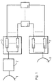
- Fig. 1 shows the components of a transponder in a communication satellite as an example for a communication channel.
- a transponder of a communication satellite comprises a receiving antenna 1 for receiving an uplink signal send from a ground station (not shown).
- An output signal of said receiving antenna 1 is fed to an input demultiplexer (IMUX) 3 after frequency conversion in frequency converter 2.
- Said input demultiplexer 3 comprises several first filters 4-1 to 4-n for separating individual signals within the signal from the antenna. Typically, one filter is provided for each signal to be separated from the other signals received via said receiving antenna 1 and corresponds to a communication channel.
- the n output signals of said input demultiplexer 3 are fed to a corresponding number of high power amplifiers 5-1 to 5-n in each of which a travelling wave tube (TWT) is employed for amplifying the output signals of said input demultiplexer 3.
- TWT travelling wave tube
- the amplifier output signals are passed through second filters 6-1 to 6-n which are part of an output multiplexer (OMUX) 7 combining the n amplifier output signals.
- the output signal of said output multiplexer 7 is fed to a transmitting antenna 8 for being transmitted to the desired area on the ground.
- the method according to the invention will be explained in following with respect to measuring two specific characteristics, namely amplitude response and group delay, of these components of the transponder communication channels, the method of the invention being especially suitable for this application.
- the same or other characteristics of other components of the communication channel can be determined by means of the method and the apparatus according to the invention.
- a pseudo noise signal PN(t) is generated by means of a pseudo noise signal generator 9, for example, a feed back shift register or a memory device in which a sequence of values of a pseudo noise signal is stored.
- the pseudo noise signal PN(t) has a very sharp autocorrelation function at zero delay. This allows to determine the time delay between the locally generated pseudo noise signal PN(t) and a received signal which is delayed due to the propagation time.
- a clean carrier signal f(t) having a variable frequency, which is varied as explained further below, is modulated with said pseudo noise signal PN(t) by means of a first multiplier 10 to form a PN modulated clean carrier signal s(t) PN(t) x f(t) .
- the chiprate of the pseudo noise signal PN(t) which determines the bandwidth of this signal, is chosen such the bandwidth of the PN modulated clean carrier signal s(t) is narrow in comparison with the expected peaks in group delay of the communication channel.
- the chiprate of the pseudo noise signal may be chosen less than 5 Mchip/s.
- the PN modulated clean carrier signal s(t) is fed to an upconverter 11 and via a high power amplifier 12 to an antenna 13 which transmits the PN modulated clean carrier signal s(t) to the transponder of the communication satellite under test.
- the transponder remains usable during the test and can be continuously supplied with a payload signal.
- the level of the transmitted PN modulated clean carrier signal s(t) is sufficiently below the level of the payload signal, for example about 15 to 25 dB or more, such that the payload signal is not notably deteriorated.
- the PN modulated clean carrier signal s(t) can be transmitted while the communication channel is in use, i.e. simultaneously with a payload signal being transmitted to the transponder of the satellite from the same or from another ground station.
- the frequency of the clean carrier signal f(t) is changed such that it sweeps from the lowest to the highest frequency of the pass band of the filters in the satellite transponder, or any other component of a general communication channel under test.
- the PN modulated clean carrier signal s(t) has a narrow bandwidth due to the pseudo noise signal PN(t) such that amplitude response and group delay of the communication channel can be determined at selected discrete frequencies, as will be described in the following.
- antenna 13 is also used to receive the signal re-transmitted by the transponder of the satellite, in other words the signal which has traveled through the communication channel.
- the output signal of antenna 13 is passed through a downconverter 14 to obtain a receive signal s'(t) which is fed to a second multiplier 15 receiving also the same but delayed pseudo noise signal PN(t).
- the delay is generated by delaying means 16 which are set such that the output of the second multiplier 15 becomes maximum.
- the receive signal s'(t) is multiplied, in other words correlated with the very same pseudo noise signal PN(t) which has been used for generating the PN modulated clean carrier signal s(t) and a recovered carrier signal f'(t) is obtained which is only delayed and attenuated in comparison with the clean carrier signal f(t).
- the amplitude response which corresponds to the attenuation of the recovered carrier signal f'(t)
- the group delay which corresponds to the delay of the recovered carrier signal f'(t), of the transponder of the satellite, as an example of a general communication channel, can easily be determined.
- the runtime of a narrowband signal at its centre frequency corresponds to the group delay of the filters if the phase can be linearly approximated in the signal bandwidth.
- the chiprate of the PN signal is determined accordingly.
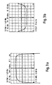
- Fig. 3a and 3b show typical measurement result for amplitude response (Fig. 3a) and group delay (Fig.3b) as obtained by the method according to the invention.
- a satellite communication channel i.e. a transponder
- the distance to the satellite can change.
- the attenuation of the path loss between the ground station and the satellite can change. Since in the above embodiment the amplitude response and the group delay is determined by subtracting the amplitude response and the group delay at the centre frequency from the respective values at other discrete frequencies, an error might occur due to the before mentioned satellite movements and atmospherical effects or other influences.
- an reference signal s R (t) can be used to compensate the before mentioned measurement error.
- the reference signal s R (t) is generated by means of a third multiplier 18 which receives a second pseudo noise signal PN R (t), which is not correlated with the first pseudo noise signal PN(t) and which is generated by a second pseudo noise generator 17, and a reference carrier signal f R (t) which may be located at a fixed frequency somewhere within the pass band of the same transponder or in the pass band of another transponder on the same satellite having a different centre frequency.
- a PN modulated reference carrier signal s R (t) is transmitted to the satellite and the reference receive signal s R '(t) is multiplied with the second pseudo noise signal PN R (T) to obtain the recovered reference signal f R '(t). While the measurement signal is swept in frequency over the transponder pass band, the frequency of the reference carrier signal f R (t) remains at a fixed frequency. Therefore, a corrected amplitude response and group delay of the communications channel can be obtained by subtracting the values of the reference signal from the values of the measurement signals at the respective time.
- a variation of the described measuring the group delay consists of measuring the phase of the reconstructed carrier of the PN modulated signal at a specified frequency very close to the first frequency, it is possible to approximate the group delay at the frequency located in the middle of both measurement frequencies by calculating the phase difference and dividing by the frequency difference.
- true noise signals can be used in the method and the apparatus according to the invention. Properties of true and pseudo noise signals are well known to those skilled in the art and are described, for example in Bernard Sklar, "Digital Communications - Fundamentals and Applications", Prentice Hall, 1988.
Landscapes
- Engineering & Computer Science (AREA)
- Physics & Mathematics (AREA)
- Computer Networks & Wireless Communication (AREA)
- Signal Processing (AREA)
- Aviation & Aerospace Engineering (AREA)
- General Physics & Mathematics (AREA)
- Astronomy & Astrophysics (AREA)
- Electromagnetism (AREA)
- Quality & Reliability (AREA)
- Radio Relay Systems (AREA)
- Monitoring And Testing Of Transmission In General (AREA)
- Mobile Radio Communication Systems (AREA)
- Measurement Of Resistance Or Impedance (AREA)
- Testing Electric Properties And Detecting Electric Faults (AREA)
Abstract
Description
- This invention relates to a method and an apparatus for determining characteristics of components of a communication channel, especially a transponder in a communication satellite under load.
- The characteristics of a communication channel may change during the lifetime of the equipment used. Various tests may be performed not only at the beginning of but also repeatedly during the lifetime to verify that the communication channel meets predetermined specifications. Usually, these tests are performed without normal traffic, i.e. without the communication channel being used for transmission of a communication signal. This scenario will be explained in the following in greater detail with reference to communication satellites but without limiting the invention disclosed further below to only this application although the invention is specifically applicable in this field.
- In a communication satellite, a communication channel is set up by a transponder of the satellite comprising several components like a receiving antenna, an input demultiplexer, a power amplifier, an output multiplexer, and a transmitting antenna. Transponder characteristics, such as amplitude response and group delay, are measured not only at the beginning of life of the spacecraft on the ground and, after launch, in orbit but also during the lifetime. These measurements are conventionally carried out without normal traffic on the transponder, i.e. without a payload signal being transmitted to and being re-transmitted by the transponder.
- The necessity of switching off the payload signal during tests represents a considerable drawback not only for the user of the transponder, since communication is interrupted, but also for the operator of the satellite since the tests have to be performed in an expedited manner to keep the interruption as short as possible. In some cases it is impossible to interrupt communications via the communication channel so that the components of these channels cannot be tested after having entered into operation.
- It is an object of the present invention to provide a method and an apparatus for determining characteristics of components of a communication channel, especially a transponder of a satellite, without the necessity to interrupt traffic via the communication channel.
- This object and other objects are achieved by a method for determining characteristics of components of a communication channel through which a payload signal is transmitted at a predetermined level, comprising: generating a first pseudo noise signal PN(t); modulating a clean carrier signal f(t) with said first pseudo noise signal PN(t) to generate a PN modulated clean carrier signal s(t); transmitting said PN modulated clean carrier signal s(t) simultaneously with said payload signal through said communication channel at a level below the level of said payload signal; receiving a receive signal s'(t) corresponding to said PN modulated clean carrier signal s(t) after having traveled through said communication channel; correlating said receive signal s'(t) with said first pseudo noise signal PN(t) to generate a recovered carrier signal f'(t); and determining characteristics of components of the communication channel on the basis of a comparison of said clean carrier signal f(t) and said recovered carrier signal f'(t).
- Advantageously, the level of said PN modulated clean carrier signal s(t) is at least 15 dB, preferably 25 dB or more below the level of said payload signal.
- In a further embodiment, said first pseudo noise signal PN(t) is a binary pseudo noise sequence, which is preferably generated by means of a feed back shift register.
- A chiprate of said first pseudo noise signal PN(t) is less than 5 MChip/s and preferably less than or equal to 2,5 MChip/s.
- In a further embodiment, said correlating of said receive signal s' (t) and said first pseudo noise signal PN(t) is achieved by delaying said first pseudo noise signal PN(t) and multiplying the delayed first pseudo noise signal PN(t) and said receive signal s'(t).
- To generate a reference, the method according to the invention further comprises: generating a second pseudo noise signal PNR(t); modulating a reference carrier signal fR(t) with said second pseudo noise signal PNR(t) to generate a PN modulated reference carrier signal sR(t); transmitting said PN modulated reference carrier signal sR(t) simultaneously with said payload signal through said communication channel at a level below the level of said payload signal; receiving a reference receive signal sR' (t) corresponding to said PN modulated reference carrier signal SR(t) after having traveled through said communication channel; correlating said reference receive signal sR' (t) with said second pseudo noise signal PNR(t) to generate a recovered reference carrier signal fR'(t); and determining characteristics of components of the communication channel also on the basis of a comparison of said reference carrier signal fR(t) and said recovered carrier signal fR' (t).
- Advantageously, the level of said PN modulated reference carrier signal sR(t) is at least 15 dB, preferably 25 dB or more below the level of said payload signal.
- In a further embodiment, said second pseudo noise signal PN(t) is a binary pseudo noise sequence which is preferably generated by means of a feed back shift register.
- In a further embodiment, said correlating of said reference receive signal SR' (t) and said second pseudo noise signal PNR(t) is achieved by delaying said second pseudo noise signal PNR(t) and multiplying the delayed second pseudo noise signal PNR(t) and said reference receive signal SR' (t).
- The method of the invention as characterised above is especially applicable when said communication channel is a transponder of a communication satellite. Said PN modulated reference signal sR(t) may be transmitted through the same transponder of the satellite, but then said second pseudo noise signal PNR(t) must not correlated with said pseudo noise signal PN(t). Said PN modulated reference signal sR(t) can also be transmitted through a different transponder of the satellite.
- The characteristics of said communication channel may be group delay and amplitude response.
- The above objects and other objects are also achieved by an apparatus for determining characteristics of components of a communication channel through which a payload signal is transmitted at a predetermined level, comprising first pseudo noise signal generating means for generating a pseudo noise signal PN(t); first modulating means for modulating a clean carrier signal f(t) with said first pseudo noise signal PN(t) to generate a PM modulated clean carrier signal s(t); transmitting means for transmitting said PN modulated clean carrier signal s(t) simultaneously with said payload signal through said communication channel at a level below the level of said payload signal; receiving means for receiving a receive signal s'(t) corresponding to said PN modulated clean carrier signal s(t) after having traveled through said communication channel; and first correlating means for correlating said receive signal s'(t) with said pseudo noise signal PN(t) to generate a recovered carrier signal f'(t).
- Advantageously, the level of said PN modulated clean carrier signal s(t) is at least 15 dB, preferably 25 dB or more below the level of said payload signal.
- In a further embodiment, said first pseudo noise signal generating means is a feed back shift register.
- A chiprate of said first pseudo noise signal PN(t) is less than 5 MChip/s preferably less than or equal to 2,5 MChip/s.
- In a further embodiment, the above apparatus comprises first delaying means for delaying said first pseudo noise signal PN(t).
- To obtain a reference, the above apparatus further comprises second pseudo noise generating means for generating a second pseudo noise signal PNR(t); second modulating means for modulating a reference carrier signal fR(t) with said second pseudo noise signal PNR(t) to generate a PN modulated reference carrier signal sR(t); transmitting means for transmitting said PN modulated reference carrier signal sR(t) simultaneously with said payload signal through said communication channel at a level below the level of said payload signal; receiving means for receiving a reference receive signal sR'(t) corresponding to said PN modulated reference carrier signal sR(t) after having traveled through said communication channel; and second correlating means for correlating said reference receive signal sR'(t) with said second pseudo noise signal PNR(t) to generate a recovered reference carrier signal fR'(t).
- Advantageously, the level of said PN modulated reference carrier signal s(t) is at least 15 dB, preferably 25 dB or more below the level of said payload signal.
- In a further embodiment, said second pseudo noise signal generating means is a feed back shift register.
- In a further embodiment, the above apparatus further comprises second delaying means for delaying said second pseudo noise signal PNR(t).
- In summary, for determining characteristics of components of a communication channel, for example of a transponder in a communication satellite, a clean carrier signal f(t) is modulated with a pseudo noise signal PN(t) and transmitted through the communication channel at a level below the level of a payload signal which is transmitted via the communication channel simultaneously. The received signal s'(t) is correlated with the same pseudo noise signal PN(t) to obtain a recovered carrier signal f'(t). The clean carrier signal f(t) and the recovered carrier signal f'(t) are used together to determine the desired characteristics. Since the PN modulated clean carrier signal s(t) is transmitted at a low level, it is possible to perform measurements without switching off the payload signal.
- The most important advantage of the method and the apparatus according to the invention is of course that the payload signal does not have to be switched off for performing the measurements. This limits considerably the downtime required for maintenance and verification of the communication channel, and thus increases availability of services.
- Another very important advantage is the fact that with this method and apparatus, it is possible to measure characteristics of components of the communication channel under realistic conditions. For example, in a satellite transponder the IMUX and OMUX filters are waveguide filters and the characteristics of these filters are changing with the temperature. Normally, the filters are not uniformly heated during operation but are heated depending on the payload signal. When the payload signal is switched off the temperature distribution changes compared to normal operation even if the test signals provide a certain power for heating the filters. Thus, with conventional methods characteristics cannot be determined under conditions present in the communication channel under load. In addition, in the proposed method the spectral power density of the measurement signal is considerably lower than the spectral power density of the payload signal, so that it is possible to characterise the behaviour of the communications channel under the most realistic circumstances.
- A further advantage of the invention is that in the case of a satellite communication channel the conversion frequency of the uplink/downlink can be measured without interruption of the payload signal and simultaneously with the other measurements.
- In the following an embodiment of the invention will be described in greater detail and with reference to the drawings.
- Fig. 1
- shows a schematic diagram of a transponder of a communication satellite;
- Fig. 2
- shows a schematic diagram of a first embodiment of an apparatus according to the invention;
- Fig. 3a and 3b
- show diagrams representing measurement result;
- Fig. 4
- shows a schematic diagram of a second embodiment of an apparatus according to the invention.
- For the purpose of describing an embodiment of the invention, Fig. 1 shows the components of a transponder in a communication satellite as an example for a communication channel.
- A transponder of a communication satellite comprises a receiving antenna 1 for receiving an uplink signal send from a ground station (not shown). An output signal of said receiving antenna 1 is fed to an input demultiplexer (IMUX) 3 after frequency conversion in
frequency converter 2. Saidinput demultiplexer 3 comprises several first filters 4-1 to 4-n for separating individual signals within the signal from the antenna. Typically, one filter is provided for each signal to be separated from the other signals received via said receiving antenna 1 and corresponds to a communication channel. The n output signals of saidinput demultiplexer 3 are fed to a corresponding number of high power amplifiers 5-1 to 5-n in each of which a travelling wave tube (TWT) is employed for amplifying the output signals of saidinput demultiplexer 3. As each of said high power amplifiers is normally operated in its saturation point, multiple signals would create intermodulation products and distortion of the signals. The amplifier output signals are passed through second filters 6-1 to 6-n which are part of an output multiplexer (OMUX) 7 combining the n amplifier output signals. The output signal of said output multiplexer 7 is fed to a transmittingantenna 8 for being transmitted to the desired area on the ground. - Since the filters provided in the input demultiplexer (IMUX) 3 and the output multiplexer (OMUX) 7 have a strong influence on the performance of the transponder, the method according to the invention will be explained in following with respect to measuring two specific characteristics, namely amplitude response and group delay, of these components of the transponder communication channels, the method of the invention being especially suitable for this application. However, the same or other characteristics of other components of the communication channel can be determined by means of the method and the apparatus according to the invention.
- According to the invention, in a ground station as shown in Fig. 2, a pseudo noise signal PN(t) is generated by means of a pseudo
noise signal generator 9, for example, a feed back shift register or a memory device in which a sequence of values of a pseudo noise signal is stored. The pseudo noise signal PN(t) has a very sharp autocorrelation function at zero delay. This allows to determine the time delay between the locally generated pseudo noise signal PN(t) and a received signal which is delayed due to the propagation time. A clean carrier signal f(t) having a variable frequency, which is varied as explained further below, is modulated with said pseudo noise signal PN(t) by means of afirst multiplier 10 to form a PN modulated clean carrier signal - The PN modulated clean carrier signal s(t) is fed to an
upconverter 11 and via ahigh power amplifier 12 to anantenna 13 which transmits the PN modulated clean carrier signal s(t) to the transponder of the communication satellite under test. However, from the viewpoint of a user transmitting a payload signal to the satellite, the transponder remains usable during the test and can be continuously supplied with a payload signal. - According to the invention, the level of the transmitted PN modulated clean carrier signal s(t) is sufficiently below the level of the payload signal, for example about 15 to 25 dB or more, such that the payload signal is not notably deteriorated. For this reason, the PN modulated clean carrier signal s(t) can be transmitted while the communication channel is in use, i.e. simultaneously with a payload signal being transmitted to the transponder of the satellite from the same or from another ground station.
- The frequency of the clean carrier signal f(t) is changed such that it sweeps from the lowest to the highest frequency of the pass band of the filters in the satellite transponder, or any other component of a general communication channel under test. The PN modulated clean carrier signal s(t) has a narrow bandwidth due to the pseudo noise signal PN(t) such that amplitude response and group delay of the communication channel can be determined at selected discrete frequencies, as will be described in the following.
- In the embodiment,
antenna 13 is also used to receive the signal re-transmitted by the transponder of the satellite, in other words the signal which has traveled through the communication channel. The output signal ofantenna 13 is passed through adownconverter 14 to obtain a receive signal s'(t) which is fed to asecond multiplier 15 receiving also the same but delayed pseudo noise signal PN(t). The delay is generated by delayingmeans 16 which are set such that the output of thesecond multiplier 15 becomes maximum. Thereby, the receive signal s'(t) is multiplied, in other words correlated with the very same pseudo noise signal PN(t) which has been used for generating the PN modulated clean carrier signal s(t) and a recovered carrier signal f'(t) is obtained which is only delayed and attenuated in comparison with the clean carrier signal f(t). Thus, the amplitude response, which corresponds to the attenuation of the recovered carrier signal f'(t), and the group delay, which corresponds to the delay of the recovered carrier signal f'(t), of the transponder of the satellite, as an example of a general communication channel, can easily be determined. The runtime of a narrowband signal at its centre frequency corresponds to the group delay of the filters if the phase can be linearly approximated in the signal bandwidth. The chiprate of the PN signal is determined accordingly. - As far as communication satellites are concerned, it is sufficient to determine the amplitude response and group delay over the pass band of a transponder only relative to the amplitude response and group delay at the centre frequency of the pass band. Therefore, it is sufficient to delay the pseudo noise signal PN(t) such that the amplitude of the recovered carrier signal f'(t) becomes maximal and to subtract the amplitude and the delay at the centre frequency from the amplitude and the delay at any other frequency in the pass band, respectively.
- Fig. 3a and 3b show typical measurement result for amplitude response (Fig. 3a) and group delay (Fig.3b) as obtained by the method according to the invention.
- In the case of a satellite communication channel, i.e. a transponder, it should be noted that, during measurements, due to the movements of the satellite the distance to the satellite can change. Also, during measurements, due to atmospherical effects the attenuation of the path loss between the ground station and the satellite can change. Since in the above embodiment the amplitude response and the group delay is determined by subtracting the amplitude response and the group delay at the centre frequency from the respective values at other discrete frequencies, an error might occur due to the before mentioned satellite movements and atmospherical effects or other influences.
- As shown in Fig. 4, an reference signal sR(t)can be used to compensate the before mentioned measurement error. In Fig. 4 the same reference signs are used for those parts already described above and reference is made to the above description of these parts. The reference signal sR(t) is generated by means of a
third multiplier 18 which receives a second pseudo noise signal PNR(t), which is not correlated with the first pseudo noise signal PN(t) and which is generated by a secondpseudo noise generator 17, and a reference carrier signal fR(t) which may be located at a fixed frequency somewhere within the pass band of the same transponder or in the pass band of another transponder on the same satellite having a different centre frequency. Like in the above embodiment, a PN modulated reference carrier signal sR(t) is transmitted to the satellite and the reference receive signal sR'(t) is multiplied with the second pseudo noise signal PNR(T) to obtain the recovered reference signal fR'(t). While the measurement signal is swept in frequency over the transponder pass band, the frequency of the reference carrier signal fR(t) remains at a fixed frequency. Therefore, a corrected amplitude response and group delay of the communications channel can be obtained by subtracting the values of the reference signal from the values of the measurement signals at the respective time. - A variation of the described measuring the group delay consists of measuring the phase of the reconstructed carrier of the PN modulated signal at a specified frequency very close to the first frequency, it is possible to approximate the group delay at the frequency located in the middle of both measurement frequencies by calculating the phase difference and dividing by the frequency difference.
- Only pseudo noise signals have been discussed above because these signals can be generated comparatively easily. However, true noise signals can be used in the method and the apparatus according to the invention. Properties of true and pseudo noise signals are well known to those skilled in the art and are described, for example in Bernard Sklar, "Digital Communications - Fundamentals and Applications", Prentice Hall, 1988.
Claims (31)
- Method for determining characteristics of components of a communication channel which is designed for transmitting a payload signal at a predetermined level, comprising:generating a first pseudo noise signal PN(t);modulating a clean carrier signal f(t) with said first pseudo noise signal PN(t) to generate a PN modulated clean carrier signal s(t);transmitting said PN modulated clean carrier signal s(t) through said communication channel at a level below the level of said payload signal;receiving a receive signal s'(t) corresponding to said PN modulated clean carrier signal s(t) after having traveled through said communication channel;correlating said receive signal s'(t) with said first pseudo noise signal PN(t) to generate a recovered carrier signal f'(t); anddetermining characteristics of components of the communication channel on the basis of a comparison of said clean carrier signal f(t) and said recovered carrier signal f'(t).
- Method according to claim 1, wherein the level of said PN modulated clean carrier signal s(t) is at least 15 dB below the level of said payload signal.
- Method according to claim 2, wherein the level of said PN modulated clean carrier signal s(t) is at least 25 dB below the level of said payload signal.
- Method according to any one of claims 1 to 3, wherein said first pseudo noise signal PN(t) is a binary pseudo noise sequence.
- Method according to claim 4, wherein said binary pseudo noise sequence is generated by means of a feed back shift register or a memory device in which a sequence of values of a pseudo noise signal is stored.
- Method according to any one of claims 1 to 5, wherein a chiprate of said first pseudo noise signal PN(t) is less than 5 Mchip/s.
- Method according to claim 6, wherein a chiprate of said first pseudo noise signal PN(t) is less than or equal to 2,5 Mchip/s.
- Method according to any one of claims 1 to 7, wherein said correlating of said receive signal s'(t) and said first pseudo noise signal PN(t) is achieved by delaying said first pseudo noise signal PN(t) and multiplying the delayed first pseudo noise signal PN(t) and said receive signal s'(t).
- Method according to any one of claims 1 to 8, further comprising:generating a second pseudo noise signal PNR(t);modulating a reference carrier signal fR(t) with said second pseudo noise signal PNR(t) to generate a PN modulated reference carrier signal sR(t);transmitting said PN modulated reference carrier signal sR(t) through said communication channel at a level below the level of said payload signal;receiving a reference receive signal sR'(t) corresponding to said PN modulated reference carrier signal sR(t) after having traveled through said communication channel;correlating said reference receive signal sR'(t) with said second pseudo noise signal PNR(t) to generate a recovered reference carrier signal fR'(t); anddetermining characteristics of components of the communication channel also on the basis of a comparison of said reference carrier signal fR(t) and said recovered carrier signal fR'(t).
- Method according to claim 9, wherein the level of said PN modulated reference carrier signal sR(t) is at least 15 dB below the level of said payload signal.
- Method according to claim 10, wherein the level of said PN modulated reference carrier signal sR(t) is at least 25 dB below the level of said payload signal.
- Method according to any one of claims 9 to 11, wherein said second pseudo noise signal PNR(t) is a binary pseudo noise sequence.
- Method according to claim 12, wherein said binary pseudo noise sequence is generated by means of a feed back shift register or a memory device in which a sequence of values of a pseudo noise signal is stored.
- Method according to any one of claims 9 to 13, wherein said correlating of said reference receive signal sR'(t) and said second pseudo noise signal PNR(t) is achieved by delaying said second pseudo noise signal PNR(t) and multiplying the delayed second pseudo noise signal PNR(t) and said reference receive signal sR'(t).
- Method according to any one of claims 1 to 14, wherein said communication channel is a transponder of a communication satellite.
- Method according to claims 14 and 15, wherein said PN modulated reference signal sR(t) is transmitted through the same transponder of the satellite and said second pseudo noise signal PNR(t) not correlated with said pseudo noise signal PN(t).
- Method according to claims 14 and 15, wherein said PN modulated reference signal SR(t) is transmitted through a different transponder of the satellite.
- Method according to any one of claims 1 to 17, wherein one of the characteristics of said communication channel is group delay and/or amplitude response.
- Apparatus for determining characteristics of components of a communication channel which is designed for transmitting a payload signal at a predetermined level, comprising:first pseudo noise signal generating means (9) for generating a pseudo noise signal PN(t);first modulating means (10) for modulating a clean carrier signal f(t) with said first pseudo noise signal PN(t) to generate a PN modulated clean carrier signal s(t);transmitting means (11, 12, 13) for transmitting said PN modulated clean carrier signal s(t) through said communication channel at a level below the level of said payload signal;receiving means (13, 14) for receiving a receive signal s'(t) corresponding to said PN modulated clean carrier signal s(t) after having traveled through said communication channel; andfirst correlating means (14) for correlating said receive signal s'(t) with said pseudo noise signal PN(t) to generate a recovered carrier signal f'(t).
- Apparatus according to claim 19, wherein the level of said PN modulated clean carrier signal s(t) is at least 15 dB below the level of said payload signal.
- Apparatus according to claim 20, wherein the level of said PN modulated clean carrier signal s(t) is at least 25 dB below the level of said payload signal.
- Apparatus according to any one of claims 19 to 21, wherein said first pseudo noise signal generating means (9) is a feed back shift register or a memory device in which a sequence of values of a pseudo noise signal is stored.
- Apparatus according to any one of claims 19 to 22, wherein a chiprate of said first pseudo noise signal PN(t) is less than 5 Mchip/s.
- Apparatus according to claim 23, wherein a chiprate of said first pseudo noise signal PN(t) is less than or equal to 2,5 Mchip/s.
- Apparatus according to any one of claims 19 to 24, further comprising first delaying means (16) for delaying said first pseudo noise signal PN(t).
- Apparatus according to any one of claims 19 to 25, further comprising:second pseudo noise generating means (17) for generating a second pseudo noise signal PNR(t);second modulating means (18) for modulating a reference carrier signal fR(t) with said second pseudo noise signal PNR(t) to generate a PN modulated reference carrier signal sR(t);transmitting means (11, 12, 13) for transmitting said PN modulated reference carrier signal sR(t) through said communication channel at a level below the level of said payload signal;receiving means (13, 14) for receiving a reference receive signal sR'(t) corresponding to said PN modulated reference carrier signal sR(t) after having traveled through said communication channel; andsecond correlating means (20) for correlating said reference receive signal sR' (t) with said second pseudo noise signal PNR(t) to generate a recovered reference carrier signal fR'(t).
- Apparatus according to claim 26, wherein the level of said PN modulated reference carrier signal s(t) is at least 15 dB below the level of said payload signal.
- Apparatus according to claim 27, wherein the level of said PN modulated reference carrier signal s(t) is at least 25 dB below the level of said payload signal.
- Apparatus according to any one of claims 26 to 28, wherein said second pseudo noise signal generating means (9) is a feed back shift register or a memory device in which a sequence of values of a pseudo noise signal is stored.
- Apparatus according to any one of claims 24 to 29, further comprising second delaying means (19) for delaying said second pseudo noise signal PNR(t).
- Apparatus according to any one of claims 19 to 30, wherein one of the characteristics of said communication channel is group delay and/or amplitude response.
Priority Applications (4)
| Application Number | Priority Date | Filing Date | Title |
|---|---|---|---|
| ES99116702T ES2207899T3 (en) | 1997-12-18 | 1997-12-18 | PROCEDURE AND DEVICE FOR THE DETERMINATION OF THE CHARACTERISTICS OF THE COMPONENTS OF A LOW-LOAD COMMUNICATION CHANNEL. |
| PT99116702T PT967744E (en) | 1997-12-18 | 1997-12-18 | METHOD AND DEVICE FOR DETERMINING CHARACTERISTICS OF COMPONENTS OF A LOAD COMMUNICATION CHANNEL |
| DE1997625012 DE69725012T2 (en) | 1997-12-18 | 1997-12-18 | Method and apparatus for determining the characteristic values of components of a communication channel under load |
| EP03020962A EP1385284A3 (en) | 1997-12-18 | 1997-12-18 | Method and apparatus for determining characteristics of components of a communication channel under load |
Applications Claiming Priority (1)
| Application Number | Priority Date | Filing Date | Title |
|---|---|---|---|
| EP97122421A EP0930734B1 (en) | 1997-12-18 | 1997-12-18 | Method and apparatus for determining characterics of components of a communication channel under load |
Related Parent Applications (1)
| Application Number | Title | Priority Date | Filing Date |
|---|---|---|---|
| EP97122421A Division EP0930734B1 (en) | 1997-12-18 | 1997-12-18 | Method and apparatus for determining characterics of components of a communication channel under load |
Publications (2)
| Publication Number | Publication Date |
|---|---|
| EP0967744A1 true EP0967744A1 (en) | 1999-12-29 |
| EP0967744B1 EP0967744B1 (en) | 2003-09-17 |
Family
ID=8227831
Family Applications (3)
| Application Number | Title | Priority Date | Filing Date |
|---|---|---|---|
| EP99116702A Expired - Lifetime EP0967744B1 (en) | 1997-12-18 | 1997-12-18 | Method and apparatus for determining characteristics of components of a communication channel under load |
| EP03020962A Withdrawn EP1385284A3 (en) | 1997-12-18 | 1997-12-18 | Method and apparatus for determining characteristics of components of a communication channel under load |
| EP97122421A Expired - Lifetime EP0930734B1 (en) | 1997-12-18 | 1997-12-18 | Method and apparatus for determining characterics of components of a communication channel under load |
Family Applications After (2)
| Application Number | Title | Priority Date | Filing Date |
|---|---|---|---|
| EP03020962A Withdrawn EP1385284A3 (en) | 1997-12-18 | 1997-12-18 | Method and apparatus for determining characteristics of components of a communication channel under load |
| EP97122421A Expired - Lifetime EP0930734B1 (en) | 1997-12-18 | 1997-12-18 | Method and apparatus for determining characterics of components of a communication channel under load |
Country Status (21)
| Country | Link |
|---|---|
| US (1) | US6535546B1 (en) |
| EP (3) | EP0967744B1 (en) |
| JP (1) | JP3554275B2 (en) |
| KR (1) | KR100417168B1 (en) |
| CN (2) | CN1327637C (en) |
| AR (1) | AR017914A1 (en) |
| AT (2) | ATE215287T1 (en) |
| AU (1) | AU739074B2 (en) |
| BR (1) | BR9813696B1 (en) |
| CA (1) | CA2315065C (en) |
| DE (1) | DE69711408T2 (en) |
| DK (2) | DK0967744T3 (en) |
| EA (1) | EA002140B1 (en) |
| ES (1) | ES2175256T3 (en) |
| HK (2) | HK1023237A1 (en) |
| IL (1) | IL136766A (en) |
| NO (1) | NO320227B1 (en) |
| PL (1) | PL192542B1 (en) |
| PT (1) | PT930734E (en) |
| TR (1) | TR200001785T2 (en) |
| WO (1) | WO1999033204A1 (en) |
Families Citing this family (16)
| Publication number | Priority date | Publication date | Assignee | Title |
|---|---|---|---|---|
| BR9917381B1 (en) * | 1999-06-18 | 2014-05-20 | Ses Astra Sa | PROCESS AND APPARATUS FOR DETERMINING CHARACTERISTICS OF COMPONENTS OF A SATELLITE COMMUNICATION CHANNEL |
| EP1083682A3 (en) * | 1999-09-10 | 2003-07-02 | TRW Inc. | Built-in self test (BIST) approach for regenerative data transmission system |
| GB0028728D0 (en) * | 2000-11-24 | 2001-01-10 | Nokia Mobile Phones Ltd | Component measures |
| US7035617B2 (en) * | 2001-01-29 | 2006-04-25 | U.S. Monolithics, L.L.C. | High power block upconverter |
| DE60123938T2 (en) | 2001-07-06 | 2007-07-05 | Ericsson Ab | Method for monitoring a redundant transmitter |
| WO2003030416A1 (en) * | 2001-10-01 | 2003-04-10 | Summitek Instruments, Inc. | Portable device used to measure passive intermodulation in radio frequency communication systems |
| US8514829B2 (en) | 2007-10-05 | 2013-08-20 | Qualcomm Incorporated | Center frequency control for wireless communication |
| US8872333B2 (en) | 2008-02-14 | 2014-10-28 | Viasat, Inc. | System and method for integrated waveguide packaging |
| US20100197257A1 (en) * | 2009-02-04 | 2010-08-05 | Qualcomm Incorporated | Adjustable receive filter responsive to frequency spectrum information |
| US8456530B2 (en) | 2009-08-18 | 2013-06-04 | Arcom Digital, Llc | Methods and apparatus for detecting and locating leakage of digital signals |
| US8650605B2 (en) | 2012-04-26 | 2014-02-11 | Arcom Digital, Llc | Low-cost leakage detector for a digital HFC network |
| AU2011218651B2 (en) | 2010-08-31 | 2014-10-09 | Viasat, Inc. | Leadframe package with integrated partial waveguide interface |
| FR2995478B1 (en) * | 2012-09-07 | 2014-09-26 | Thales Sa | METHOD FOR CHARACTERIZING A TRANSMISSION ANTENNA OF A SATELLITE IN ORBIT AND ASSOCIATED SYSTEM |
| US9933950B2 (en) | 2015-01-16 | 2018-04-03 | Sandisk Technologies Llc | Storage operation interrupt |
| LU101119B1 (en) * | 2019-02-12 | 2020-08-12 | Université Du Luxembourg | Method and device for adaptive in-orbit testing of a satellite transponder |
| CN113815909B (en) * | 2021-09-09 | 2023-10-27 | 中国人民解放军63920部队 | Uplink determining method and device for peer-to-peer mode combination configuration spacecraft |
Citations (4)
| Publication number | Priority date | Publication date | Assignee | Title |
|---|---|---|---|---|
| US4637017A (en) * | 1984-05-21 | 1987-01-13 | Communications Satellite Corporation | Monitoring of input backoff in time division multiple access communication satellites |
| DE3644175A1 (en) * | 1986-12-23 | 1988-07-14 | Messerschmitt Boelkow Blohm | Method for transmitting data using satellites |
| EP0420230A2 (en) * | 1989-09-29 | 1991-04-03 | Hughes Aircraft Company | Feed forward spread spectrum signal processor |
| US5036523A (en) * | 1989-10-03 | 1991-07-30 | Geostar Corporation | Automatic frequency control of satellite transmitted spread spectrum signals |
Family Cites Families (7)
| Publication number | Priority date | Publication date | Assignee | Title |
|---|---|---|---|---|
| US4279018A (en) * | 1979-03-06 | 1981-07-14 | Nasa | PN Lock indicator for dithered PN code tracking loop |
| JPS6032555B2 (en) * | 1979-09-28 | 1985-07-29 | 株式会社日立製作所 | Laser beam welding rotating head |
| US5559828A (en) * | 1994-05-16 | 1996-09-24 | Armstrong; John T. | Transmitted reference spread spectrum communication using a single carrier with two mutually orthogonal modulated basis vectors |
| US5546421A (en) * | 1994-08-22 | 1996-08-13 | Martin Marietta Corp. | Self compensating spread-spectrum hybrid |
| US5731993A (en) * | 1996-09-09 | 1998-03-24 | Hughes Electronics | Nonlinear amplifier operating point determination system and method |
| US5943331A (en) * | 1997-02-28 | 1999-08-24 | Interdigital Technology Corporation | Orthogonal code synchronization system and method for spread spectrum CDMA communications |
| DE69701473T2 (en) * | 1997-12-18 | 2000-08-03 | Europ Des Satellites Betzdorf | Method and device for determining an operating point of a non-linear amplifier in a transmission channel |
-
1997
- 1997-12-18 DE DE69711408T patent/DE69711408T2/en not_active Expired - Lifetime
- 1997-12-18 PT PT97122421T patent/PT930734E/en unknown
- 1997-12-18 DK DK99116702T patent/DK0967744T3/en active
- 1997-12-18 EP EP99116702A patent/EP0967744B1/en not_active Expired - Lifetime
- 1997-12-18 AT AT97122421T patent/ATE215287T1/en active
- 1997-12-18 ES ES97122421T patent/ES2175256T3/en not_active Expired - Lifetime
- 1997-12-18 DK DK97122421T patent/DK0930734T3/en active
- 1997-12-18 EP EP03020962A patent/EP1385284A3/en not_active Withdrawn
- 1997-12-18 AT AT99116702T patent/ATE250303T1/en active
- 1997-12-18 EP EP97122421A patent/EP0930734B1/en not_active Expired - Lifetime
-
1998
- 1998-12-17 WO PCT/EP1998/008307 patent/WO1999033204A1/en active IP Right Grant
- 1998-12-17 AU AU24149/99A patent/AU739074B2/en not_active Expired
- 1998-12-17 PL PL341200A patent/PL192542B1/en unknown
- 1998-12-17 EA EA200000670A patent/EA002140B1/en not_active IP Right Cessation
- 1998-12-17 KR KR10-2000-7006750A patent/KR100417168B1/en not_active IP Right Cessation
- 1998-12-17 TR TR2000/01785T patent/TR200001785T2/en unknown
- 1998-12-17 CN CNB031581595A patent/CN1327637C/en not_active Expired - Lifetime
- 1998-12-17 CA CA002315065A patent/CA2315065C/en not_active Expired - Lifetime
- 1998-12-17 US US09/213,171 patent/US6535546B1/en not_active Expired - Lifetime
- 1998-12-17 IL IL13676698A patent/IL136766A/en not_active IP Right Cessation
- 1998-12-17 BR BRPI9813696-8A patent/BR9813696B1/en not_active IP Right Cessation
- 1998-12-17 CN CNB988134357A patent/CN1149762C/en not_active Expired - Lifetime
- 1998-12-17 JP JP2000525994A patent/JP3554275B2/en not_active Expired - Lifetime
- 1998-12-18 AR ARP980106506A patent/AR017914A1/en active IP Right Grant
-
2000
- 2000-04-10 HK HK00102162A patent/HK1023237A1/en not_active IP Right Cessation
- 2000-06-16 NO NO20003157A patent/NO320227B1/en not_active IP Right Cessation
-
2004
- 2004-07-14 HK HK04105149A patent/HK1062236A1/en not_active IP Right Cessation
Patent Citations (4)
| Publication number | Priority date | Publication date | Assignee | Title |
|---|---|---|---|---|
| US4637017A (en) * | 1984-05-21 | 1987-01-13 | Communications Satellite Corporation | Monitoring of input backoff in time division multiple access communication satellites |
| DE3644175A1 (en) * | 1986-12-23 | 1988-07-14 | Messerschmitt Boelkow Blohm | Method for transmitting data using satellites |
| EP0420230A2 (en) * | 1989-09-29 | 1991-04-03 | Hughes Aircraft Company | Feed forward spread spectrum signal processor |
| US5036523A (en) * | 1989-10-03 | 1991-07-30 | Geostar Corporation | Automatic frequency control of satellite transmitted spread spectrum signals |
Also Published As
Similar Documents
| Publication | Publication Date | Title |
|---|---|---|
| US6535546B1 (en) | Method and apparatus for determining characteristics of components of a communication channel under load | |
| JP4197869B2 (en) | Method and apparatus for determining device characteristics of a communication channel | |
| EP0929164B1 (en) | Method and apparatus for determining an operating point of a non-linear amplifier of a communication channel | |
| RU2513696C2 (en) | Tuning multiport amplifier | |
| US5731993A (en) | Nonlinear amplifier operating point determination system and method | |
| US7155216B2 (en) | Functionality test in a base transceiver station | |
| Gandhi et al. | Design and development of dynamic satellite link emulator with experimental validation | |
| CZ20002192A3 (en) | Process and apparatus for determining properties of communication apparatus elements under load | |
| ES2207899T3 (en) | PROCEDURE AND DEVICE FOR THE DETERMINATION OF THE CHARACTERISTICS OF THE COMPONENTS OF A LOW-LOAD COMMUNICATION CHANNEL. | |
| Carey et al. | SATCOM simulator speeds MSS deployment and lowers costs | |
| Kleine-Ostmann et al. | A new spread-spectrum measurement method for satellite transponder in-orbit testing | |
| Rathnakara et al. | In-orbit testing of satellite communication payloads | |
| de Martino et al. | Performance verification of the Italsat regenerative downlink VIA computer simulation |
Legal Events
| Date | Code | Title | Description |
|---|---|---|---|
| PUAI | Public reference made under article 153(3) epc to a published international application that has entered the european phase |
Free format text: ORIGINAL CODE: 0009012 |
|
| AC | Divisional application: reference to earlier application |
Ref document number: 930734 Country of ref document: EP |
|
| AK | Designated contracting states |
Kind code of ref document: A1 Designated state(s): AT BE CH DE DK ES FI FR GB GR IE IT LI LU MC NL PT SE |
|
| AX | Request for extension of the european patent |
Free format text: AL;LT;LV;MK;RO;SI |
|
| 17P | Request for examination filed |
Effective date: 20000620 |
|
| AKX | Designation fees paid |
Free format text: AT BE CH DE DK ES FI FR GB GR IE IT LI LU MC NL PT SE |
|
| RIN1 | Information on inventor provided before grant (corrected) |
Inventor name: HARLES, GUY Inventor name: BETHSCHEIDER, GERHARD |
|
| RAP1 | Party data changed (applicant data changed or rights of an application transferred) |
Owner name: SES ASTRA S.A. |
|
| GRAH | Despatch of communication of intention to grant a patent |
Free format text: ORIGINAL CODE: EPIDOS IGRA |
|
| GRAS | Grant fee paid |
Free format text: ORIGINAL CODE: EPIDOSNIGR3 |
|
| GRAA | (expected) grant |
Free format text: ORIGINAL CODE: 0009210 |
|
| AC | Divisional application: reference to earlier application |
Ref document number: 0930734 Country of ref document: EP Kind code of ref document: P |
|
| AK | Designated contracting states |
Kind code of ref document: B1 Designated state(s): AT BE CH DE DK ES FI FR GB GR IE IT LI LU MC NL PT SE |
|
| REG | Reference to a national code |
Ref country code: GB Ref legal event code: FG4D |
|
| REG | Reference to a national code |
Ref country code: CH Ref legal event code: EP |
|
| REG | Reference to a national code |
Ref country code: SE Ref legal event code: TRGR |
|
| REF | Corresponds to: |
Ref document number: 69725012 Country of ref document: DE Date of ref document: 20031023 Kind code of ref document: P |
|
| REG | Reference to a national code |
Ref country code: IE Ref legal event code: FG4D |
|
| REG | Reference to a national code |
Ref country code: CH Ref legal event code: NV Representative=s name: N&G PATENT SERVICES SA |
|
| REG | Reference to a national code |
Ref country code: DK Ref legal event code: T3 Ref country code: GR Ref legal event code: EP Ref document number: 20030404833 Country of ref document: GR |
|
| PG25 | Lapsed in a contracting state [announced via postgrant information from national office to epo] |
Ref country code: MC Free format text: LAPSE BECAUSE OF NON-PAYMENT OF DUE FEES Effective date: 20031231 |
|
| ET | Fr: translation filed | ||
| REG | Reference to a national code |
Ref country code: ES Ref legal event code: FG2A Ref document number: 2207899 Country of ref document: ES Kind code of ref document: T3 |
|
| PLBE | No opposition filed within time limit |
Free format text: ORIGINAL CODE: 0009261 |
|
| STAA | Information on the status of an ep patent application or granted ep patent |
Free format text: STATUS: NO OPPOSITION FILED WITHIN TIME LIMIT |
|
| 26N | No opposition filed |
Effective date: 20040618 |
|
| REG | Reference to a national code |
Ref country code: CH Ref legal event code: PCAR Free format text: NOVAGRAAF INTERNATIONAL SA;25, AVENUE DU PAILLY;1220 LES AVANCHETS (CH) |
|
| REG | Reference to a national code |
Ref country code: CH Ref legal event code: PFA Owner name: SES ASTRA S.A. Free format text: SES ASTRA S.A.# #6815 CHATEAU DE BETZDORF (LU) -TRANSFER TO- SES ASTRA S.A.# #6815 CHATEAU DE BETZDORF (LU) |
|
| REG | Reference to a national code |
Ref country code: FR Ref legal event code: PLFP Year of fee payment: 19 |
|
| REG | Reference to a national code |
Ref country code: FR Ref legal event code: PLFP Year of fee payment: 20 |
|
| PGFP | Annual fee paid to national office [announced via postgrant information from national office to epo] |
Ref country code: FI Payment date: 20161215 Year of fee payment: 20 Ref country code: DE Payment date: 20161215 Year of fee payment: 20 Ref country code: NL Payment date: 20161215 Year of fee payment: 20 Ref country code: IE Payment date: 20161026 Year of fee payment: 20 Ref country code: DK Payment date: 20161121 Year of fee payment: 20 Ref country code: LU Payment date: 20161227 Year of fee payment: 20 Ref country code: CH Payment date: 20161222 Year of fee payment: 20 Ref country code: GB Payment date: 20161114 Year of fee payment: 20 |
|
| PGFP | Annual fee paid to national office [announced via postgrant information from national office to epo] |
Ref country code: SE Payment date: 20161118 Year of fee payment: 20 Ref country code: ES Payment date: 20161220 Year of fee payment: 20 Ref country code: BE Payment date: 20161215 Year of fee payment: 20 Ref country code: IT Payment date: 20161220 Year of fee payment: 20 Ref country code: GR Payment date: 20161213 Year of fee payment: 20 Ref country code: FR Payment date: 20161220 Year of fee payment: 20 Ref country code: AT Payment date: 20161128 Year of fee payment: 20 |
|
| PGFP | Annual fee paid to national office [announced via postgrant information from national office to epo] |
Ref country code: PT Payment date: 20170209 Year of fee payment: 20 |
|
| REG | Reference to a national code |
Ref country code: DE Ref legal event code: R071 Ref document number: 69725012 Country of ref document: DE |
|
| REG | Reference to a national code |
Ref country code: NL Ref legal event code: MK Effective date: 20171217 |
|
| REG | Reference to a national code |
Ref country code: CH Ref legal event code: PL |
|
| REG | Reference to a national code |
Ref country code: DK Ref legal event code: EUP Effective date: 20171218 |
|
| REG | Reference to a national code |
Ref country code: GB Ref legal event code: PE20 Expiry date: 20171217 |
|
| REG | Reference to a national code |
Ref country code: IE Ref legal event code: MK9A |
|
| REG | Reference to a national code |
Ref country code: SE Ref legal event code: EUG |
|
| REG | Reference to a national code |
Ref country code: AT Ref legal event code: MK07 Ref document number: 250303 Country of ref document: AT Kind code of ref document: T Effective date: 20171218 |
|
| REG | Reference to a national code |
Ref country code: BE Ref legal event code: MK Effective date: 20171218 |
|
| PG25 | Lapsed in a contracting state [announced via postgrant information from national office to epo] |
Ref country code: GB Free format text: LAPSE BECAUSE OF EXPIRATION OF PROTECTION Effective date: 20171217 Ref country code: PT Free format text: LAPSE BECAUSE OF EXPIRATION OF PROTECTION Effective date: 20171227 |
|
| PG25 | Lapsed in a contracting state [announced via postgrant information from national office to epo] |
Ref country code: IE Free format text: LAPSE BECAUSE OF EXPIRATION OF PROTECTION Effective date: 20171218 |
|
| REG | Reference to a national code |
Ref country code: ES Ref legal event code: FD2A Effective date: 20180508 |
|
| PG25 | Lapsed in a contracting state [announced via postgrant information from national office to epo] |
Ref country code: ES Free format text: LAPSE BECAUSE OF EXPIRATION OF PROTECTION Effective date: 20171219 |