EP0965152B1 - Resonant antenna - Google Patents
Resonant antenna Download PDFInfo
- Publication number
- EP0965152B1 EP0965152B1 EP98912379A EP98912379A EP0965152B1 EP 0965152 B1 EP0965152 B1 EP 0965152B1 EP 98912379 A EP98912379 A EP 98912379A EP 98912379 A EP98912379 A EP 98912379A EP 0965152 B1 EP0965152 B1 EP 0965152B1
- Authority
- EP
- European Patent Office
- Prior art keywords
- antenna
- conductor section
- resonator
- fact
- conductor
- Prior art date
- Legal status (The legal status is an assumption and is not a legal conclusion. Google has not performed a legal analysis and makes no representation as to the accuracy of the status listed.)
- Expired - Lifetime
Links
- 239000004020 conductor Substances 0.000 claims abstract description 97
- 239000000758 substrate Substances 0.000 claims abstract description 19
- 239000003989 dielectric material Substances 0.000 claims abstract description 3
- 238000010168 coupling process Methods 0.000 claims description 10
- 238000005859 coupling reaction Methods 0.000 claims description 10
- 230000008878 coupling Effects 0.000 claims description 9
- 239000011248 coating agent Substances 0.000 claims description 8
- 238000000576 coating method Methods 0.000 claims description 8
- 230000007613 environmental effect Effects 0.000 claims description 4
- 239000003990 capacitor Substances 0.000 abstract description 3
- 239000013307 optical fiber Substances 0.000 abstract 2
- 238000005516 engineering process Methods 0.000 description 6
- 230000005855 radiation Effects 0.000 description 6
- 239000011888 foil Substances 0.000 description 5
- RYGMFSIKBFXOCR-UHFFFAOYSA-N Copper Chemical compound [Cu] RYGMFSIKBFXOCR-UHFFFAOYSA-N 0.000 description 2
- 239000004793 Polystyrene Substances 0.000 description 2
- XAGFODPZIPBFFR-UHFFFAOYSA-N aluminium Chemical compound [Al] XAGFODPZIPBFFR-UHFFFAOYSA-N 0.000 description 2
- 229910052782 aluminium Inorganic materials 0.000 description 2
- 229910052802 copper Inorganic materials 0.000 description 2
- 239000010949 copper Substances 0.000 description 2
- 238000010586 diagram Methods 0.000 description 2
- 229920002223 polystyrene Polymers 0.000 description 2
- 230000001413 cellular effect Effects 0.000 description 1
- 238000010276 construction Methods 0.000 description 1
- 238000012938 design process Methods 0.000 description 1
- 238000006073 displacement reaction Methods 0.000 description 1
- 230000005684 electric field Effects 0.000 description 1
- 238000005286 illumination Methods 0.000 description 1
- 230000001939 inductive effect Effects 0.000 description 1
- 230000001788 irregular Effects 0.000 description 1
- 230000005404 monopole Effects 0.000 description 1
- 230000010355 oscillation Effects 0.000 description 1
- 230000000717 retained effect Effects 0.000 description 1
- 230000003595 spectral effect Effects 0.000 description 1
Images


Classifications
-
- H—ELECTRICITY
- H01—ELECTRIC ELEMENTS
- H01Q—ANTENNAS, i.e. RADIO AERIALS
- H01Q1/00—Details of, or arrangements associated with, antennas
- H01Q1/40—Radiating elements coated with or embedded in protective material
-
- H—ELECTRICITY
- H01—ELECTRIC ELEMENTS
- H01Q—ANTENNAS, i.e. RADIO AERIALS
- H01Q9/00—Electrically-short antennas having dimensions not more than twice the operating wavelength and consisting of conductive active radiating elements
- H01Q9/04—Resonant antennas
-
- H—ELECTRICITY
- H01—ELECTRIC ELEMENTS
- H01Q—ANTENNAS, i.e. RADIO AERIALS
- H01Q1/00—Details of, or arrangements associated with, antennas
- H01Q1/12—Supports; Mounting means
- H01Q1/22—Supports; Mounting means by structural association with other equipment or articles
- H01Q1/24—Supports; Mounting means by structural association with other equipment or articles with receiving set
-
- H—ELECTRICITY
- H01—ELECTRIC ELEMENTS
- H01Q—ANTENNAS, i.e. RADIO AERIALS
- H01Q1/00—Details of, or arrangements associated with, antennas
- H01Q1/36—Structural form of radiating elements, e.g. cone, spiral, umbrella; Particular materials used therewith
- H01Q1/38—Structural form of radiating elements, e.g. cone, spiral, umbrella; Particular materials used therewith formed by a conductive layer on an insulating support
-
- H—ELECTRICITY
- H01—ELECTRIC ELEMENTS
- H01Q—ANTENNAS, i.e. RADIO AERIALS
- H01Q13/00—Waveguide horns or mouths; Slot antennas; Leaky-waveguide antennas; Equivalent structures causing radiation along the transmission path of a guided wave
- H01Q13/08—Radiating ends of two-conductor microwave transmission lines, e.g. of coaxial lines, of microstrip lines
Definitions
- the invention relates to an antenna for receiving and transmitting of electromagnetic microwaves of wavelengths ⁇ from a substrate layer made of low dielectric Material that has a conductive ground plane on one side has and the opposite side conductive in the form of Microstrip lines is structured.
- the scope of the invention extends ostensibly in the mobile and handheld technology sector within the spectral range between 890 MHz and 960 MHz or 1710 MHz and 1890 MHz by the component according to the invention into the corresponding end device and handheld technology is integrated.
- Known antenna solutions for the field of mobile radio applications are based on linear antenna designs in form of monopole arrangements in a shortened or unabridged version. These linear antennas are both externally mountable On-board antennas as well as directly with the end device coupled components known, as well as with different Indicative factor and efficiency, where these components in the azimuthal plane are only round strands are.
- Known flat antenna solutions are based on two-dimensional, dipole-like configurations, whose directional diagram is irregular and in connection with the the respective antenna carrier or antenna body have a significant radiation field deformation. The radiation properties related to the area of application are clear from those of the classic linear antennas inferior. There are also targeted blanking properties of the radiation diagram undetectable. Farther no solutions are known whose electromagnetic or radiation properties based on asymmetrical and open waveguide technology, especially microstrip technology, using foil conductors or foil-like guide surfaces can be achieved.
- the one shown in the patent DE 41 13 277 and azimuthal omnidirectional antenna configuration is only possible from a film as a mechanical structural support, said antenna component having an outside of the terminal equipment arranged head capacity is.
- the main radiation direction an inclination with respect to the elevation values of approx. (minus) -30 ° (angular degree), that is, a negative one Has elevation angle.
- a disadvantage of the known antenna configurations is hence that they are either in the azimuthal plane exclusively are omnidirectional or only within the negative Radiate elevation angle range.
- the object of the present invention is a system integrable Antenna component with the smallest possible area Expansion with azimuthal as possible one-sided Directionality, that is the preferred illumination of a Spatial hemisphere and a limited angular displacement of the elevation-related directivity within the positive To provide elevation angle range.
- the antenna according to the invention which can also be referred to as a foil radiator, is a modified ⁇ / 4 radiator which is short-circuited to ground on one side.
- the elongated conductor section which serves as a resonator, is made shorter than ⁇ ⁇ / 4.
- the resonator becomes inductive and the vibration condition is not met.
- an end capacitance is generated at the end of the resonator opposite the short-circuited side.
- This end capacitance is generated by at least one additional additional conductor section, one end of which connects to the end of the resonator opposite the short-circuited side and the other end of which forms an open circuit.
- the length of the additional further conductor sections determine the vibration condition and thus the resulting resonance frequency of the entire structure.
- Various embodiments of the conductor sections at the end of the resonator are conceivable for realizing a defined end capacitance for maintaining the vibration condition.
- the end capacitance can be realized by one or more lines of appropriate length, which do not necessarily have to run parallel to one another or to the resonator. All lines can also be designed in any curved shape and not just in a straight shape.
- the electrical properties of this antenna e.g. Quality, Impedance bandwidth, efficiency and gain depend on the size of the mechanical reduction (reduction) achieved, the width of the resonator, the distance between the resonator and the end capacitance sections, the effective permittivity constant, the substrate thickness or of the dielectric loss angle.
- an essential feature of the invention is that the resonators implemented in microstrip technology for receiving the microwaves are shorter than ⁇ ⁇ / 4, which enables a particularly compact and small construction to be achieved. Because the resonator length is chosen to be shorter than ⁇ ⁇ / 4, the oscillation condition is no longer met, as already explained. The required end capacities are realized by further line sections. An increase in the frequency bandwidth can be achieved by additional radiator elements through electromagnetic coupling. This is done by additional microstrip lines, which are arranged at certain distances from the resonator and its end capacitors.
- resonators can be arranged spatially nested in one another and matched to the required frequency bands.
- the individual antennas do not have to be in one plane but can also be arranged in layers one above the other. It is also possible that several antenna arrangements are provided per layer, so that more than two different frequency bands can be operated. This makes it possible for a mobile radio telephone to be able to communicate with different mobile radio networks.
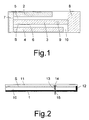
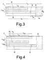
- FIG. 1 shows an antenna according to the invention with a film-like low dielectric carrier 10, which is one-sided with a conductive structure S consisting of parallel to each other and rectilinear conductor sections 2, 3 and 4 of different lengths coated is, the conductor section 3 is conductive and one-sided is connected to a ground plane 8, which in turn, as shown in Figure 2, via a conductive coating the cross-sectional area of the carrier substrate 10 is connected to ground level 1.
- the ground surface 8 by means of or a plurality of contact pins covering the dielectric substrate layer 10 reach through, with the ground level 1 in connection his.
- the conductive coating of the Cross-sectional area of the carrier substrate 10 does not have to have the entire width of the antenna, but it can be a partial coating of the film cross-sectional area made become.
- the conductor sections 2, 3 and 4 are each by a gap 5.6 of defined spa width from one another arranged separately, the conductor sections 2, 3 and 4 in each case by a strip-shaped strip running in the transverse direction Conductor section 7 of defined section length and -Width are conductively interconnected, the in Conductor section running transversely on that of the ground contact 8 opposite end of the conductor section Antenna is arranged.
- the input impedance of the microstrip array is along the location of the coupling 9 the line of symmetry of the conductor section 3 determines the again from the resulting length of the conductor sections 2 and 4 depends, the signal coupling in and out on Location 9 via a circular coaxial orifice slit or rectangular aperture.
- Dielectric constant as well as defined geometry is influenced or minimized.
- the dielectric carrier layer 10 is in particular one Polystyrene film with a layer thickness of 1 mm, which is one-sided and all over with a copper or aluminum foil Layer thickness between 0.01 mm and 0.5 mm is provided forms the ground plane.
- the dielectric layer 11 also has one Layer thickness of approx. 1 mm.
- the antenna has a length L A of 119 mm and a width B A of 40 mm.
- the length L 8 of the ground surface 8 is 20 mm.
- the distance L 5 from the ground surface 8 to the feed point of the antenna 9 is also 20 mm.
- the diameter of the aperture 15 is 4.1 mm.
- the length of the conductor sections K 1 and K 2 forming the final capacitance are 82.6 mm and 56.7 mm.
- the length L A of the conductor section 3 or R forming the resonator is 85.7 mm.
- the width of the conductor section 2 is 11.5 mm and the width of the conductor section 4 is 9.5 mm.
- the width of the resonator conductor section is 12 mm.
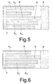
- FIG. 3 shows a radiator according to the invention, in which only one parallel to the resonator conductor section 3 or R arranged conductor section K forms the final capacitance.
- FIG. 4 shows an emitter according to the invention, in which the. Sndcapacitance is formed by two parallel conductor sections K 1 and K 2 , which are arranged on one side of the resonator conductor section R.
- an antenna can be configured in which the resulting end capacitance is realized by three or four conductor sections K 1 to K 4 .
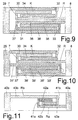
- FIG. 7 shows a further embodiment of the invention Antenna where the end capacitance is Conductor sections 16 and 17 are not rectilinear, but have a rectangular shape.
- FIG. 8 shows antennas in which the frequency bandwidth the antenna through electromagnetic coupling with additional conductor elements, which on the same dielectric carrier substrate are arranged, is adjusted or enlarged.
- the antenna according to FIG. 8 corresponds in its basic structure to the antenna according to FIG. 3, a U-shaped conductor section 19, 20, 21 with its one leg 21 in the gap between the resonator conductor section 3 and the final capacity. Head section 2 engages.
- the other leg 19 is with an additional ground surface 18 in connection, which in turn corresponding to the ground plane 9 with the ground plane i is connected.
- the basic structure of FIG. 9 corresponds of Figure 1, with two additional U-shaped Conductor sections 23 to 28 are provided, which each with its one leg 27, 28 in the through the Intervene conductor sections 2, R, 4 formed column.
- FIGS. 9 and 10 show further possible configurations the antenna according to the invention, the arrangement of the additional, the coupling to increase the frequency bandwidths influencing conductor sections 30 to 38 is in principle arbitrary. It is also conceivable that the Interconnect conductor sections spirally so that on relatively small space a long parallel routing of conductor sections is produced.
- FIGS. 11 to 14 show antennas in which two antenna signals can be coupled in or out, as a result of which two frequency bands can be received or operated simultaneously using only one film antenna. Due to the different design of the resonator conductor sections R a and R b , the resonance conditions in connection with the conductor sections 41a, b and 42a, b and the locations 43a, 43b of the coupling-out of the electromagnetic waves are determined. Due to the nesting of the two radiator arrangements, they can be arranged in a confined space.
- FIG. 12 shows a further embodiment of an antenna with two connections 51a, 51b for dielectric waveguides, only that shown in Figure 8 Spotlight arrangement in different dimensions arranged side by side on a substrate carrier are.
- Figures 13 and 14 show a multi-layer antenna, at which the antennas according to the invention one above the other in several layers are sandwiched, one each Antenna the vibration conditions for the frequencies of a corresponds to certain cellular network. Because of the different Resonance frequencies interfere with one another arranged strahiunas structures only insignificantly. Compared to the arrangement according to FIG. 2, the Layering the radiator structures less space needed, whereby the antenna according to Figure 13 more compact and thus the housing of a mobile phone that encloses it can be made relatively small.
- FIG. 14 shows the antenna according to FIG. 13 in cross section.
- the conductive coating 12a, b of the cross-sectional area of the carrier substrates 10a and 10b is conductively connected to the structured layers S A and S B.
- Such a conductive cross-sectional coating can also be provided on the opposite side, depending on the antenna design.
Landscapes
- Waveguide Aerials (AREA)
- Input Circuits Of Receivers And Coupling Of Receivers And Audio Equipment (AREA)
- Details Of Aerials (AREA)
- Burglar Alarm Systems (AREA)
- Control Of Motors That Do Not Use Commutators (AREA)
Abstract
Description
Die Erfindung betrifft eine Antenne zum Empfang und Senden von elektromagnetischen Mikrowellen der Wellenlängen λ, bestehend aus einer Substratschicht aus niederdielektrischem Material, welche auf einer Seite eine leitfähige Masseebene hat und deren gegenüberliegende Seite leitfähig in Form von Mikrostreifenleitungen strukturiert ist.The invention relates to an antenna for receiving and transmitting of electromagnetic microwaves of wavelengths λ from a substrate layer made of low dielectric Material that has a conductive ground plane on one side has and the opposite side conductive in the form of Microstrip lines is structured.
Der Anwendungsbereich der Erfindung erstreckt sich vordergründig auf den Sektor der Mobilfunk- und Handheld-Technik innerhalb der Spektralbereiche zwischen 890 MHz und 960 MHz oder 1710 MHz und 1890 MHz, indem die erfindungsgemäße Komponente in die entsprechenden Endgeräte- und Handheld-Technik integriert wird.The scope of the invention extends ostensibly in the mobile and handheld technology sector within the spectral range between 890 MHz and 960 MHz or 1710 MHz and 1890 MHz by the component according to the invention into the corresponding end device and handheld technology is integrated.
Bekannte Antennenlösungen für den Bereich der Mobilfunkanwendungen beruhen auf Linearantennenkonzeptionen in Form von Monopolanordnungen in verkürzter oder unverkürzter Ausführung. Diese Linearantennen sind sowohl als extern montierbare Bordantennen als auch als unmittelbar mit dem Endgerät gekoppelte Komponenten bekannt, sowie mit unterschiedlichem Richtfaktor und Wirkungsgrad behaftet, wobei diese Komponenten in der Azimutalebene ausschließlich rundstraniend sind. Bekannte Flachantennenlösungen beruhen auf flächenhaft angeordneten, dipolähnlichen Konfigurationen, deren Richtdiagramm unregelmäßig und in Verbindung mit dem jeweiligen Antennenträger bzw. Antennenkörper die Merkmale einer signifikanten Strahlungsfelddeformation aufweisen. Die auf den Anwendungsbereich bezogenen Strahlungseigenschaften sind denen der klassischen Linearantennen deutlich unterlegen. Gleichfalls sind gezielte Ausblendungseigenschaften des Strahlungsdiagramms nicht nachweisbar. Weiterhin sind keine Lösungen bekannt, deren elektromagnetische bzw. Strahlungseigenschaften auf der Basis unsymmetrischer und offener Wellenleitertechnik, insbesondere der Mikrostreifentechnik, unter Verwendung von Folienleitern oder folienähnlichen Leitflächen erzielt werden.Known antenna solutions for the field of mobile radio applications are based on linear antenna designs in form of monopole arrangements in a shortened or unabridged version. These linear antennas are both externally mountable On-board antennas as well as directly with the end device coupled components known, as well as with different Indicative factor and efficiency, where these components in the azimuthal plane are only round strands are. Known flat antenna solutions are based on two-dimensional, dipole-like configurations, whose directional diagram is irregular and in connection with the the respective antenna carrier or antenna body have a significant radiation field deformation. The radiation properties related to the area of application are clear from those of the classic linear antennas inferior. There are also targeted blanking properties of the radiation diagram undetectable. Farther no solutions are known whose electromagnetic or radiation properties based on asymmetrical and open waveguide technology, especially microstrip technology, using foil conductors or foil-like guide surfaces can be achieved.
Die in der Patentschrift DE 41 13 277 dargestellte und azimutal rundstrahlende Antennenkonfiguration geht ausschließlich von einer Folie als mechanischen Strukturträger aus, wobei die benannte Antennenkomponente mit einer außerhalb des Endgerätcontainments angeordneten Kopfkapazität behaftet ist. In gleicher Weise.geht die in der Patentschrift DE 41 21 333 dargestellte und azimutal rundstrahlende Antennenkonfiguration von einer elektrisch nicht leitenden Folie als mechanischem Strukturträger aus, wobei die Hauptstrahlungsrichtung bezüglich der Elevationswerte eine Neigung von ca. (Minus) -30° (Winkelgrad), das heißt, einen negativen Elevationswinkel aufweist.The one shown in the patent DE 41 13 277 and azimuthal omnidirectional antenna configuration is only possible from a film as a mechanical structural support, said antenna component having an outside of the terminal equipment arranged head capacity is. In the same way. That in the patent DE 41 21 333 shown and azimuthal omnidirectional antenna configuration of an electrically non-conductive film as a mechanical structure support, the main radiation direction an inclination with respect to the elevation values of approx. (minus) -30 ° (angular degree), that is, a negative one Has elevation angle.
Nachteilig bei den bekannten Antennenkonfigurationen ist somit, daß sie entweder in azimutaler Ebene ausschließlich rundstrahlend sind oder lediglich innerhalb des negativen Elevationswinkelbereiches strahlen.A disadvantage of the known antenna configurations is hence that they are either in the azimuthal plane exclusively are omnidirectional or only within the negative Radiate elevation angle range.
Aufgabe der vorliegenden Erfindung ist es, eine systemintegrierbare Antennenkomponente mit möglichst kleiner flächenhafter Ausdehnung mit möglichst einseitiger azimutaler Richtwirkung, das heißt der bevorzugten Ausleuchtung einer Raumhemisphäre sowie einer begrenzten Winkelversetzung der elevationsbezogenen Richtwirkung innerhalb des positiven Elevationswinkelbereiches bereitzustellen.The object of the present invention is a system integrable Antenna component with the smallest possible area Expansion with azimuthal as possible one-sided Directionality, that is the preferred illumination of a Spatial hemisphere and a limited angular displacement of the elevation-related directivity within the positive To provide elevation angle range.
Diese Aufgabe wird erfindungsgemäß durch die Merkmale des
Kennzeichnenden Teils des Anspruchs 1 sowie der suf den Anspruch
1 rückbezogenen Unteransprüche gelöst.This object is achieved by the features of
Characteristic part of
Bei der erfindungsgemäßen Antenne, welche auch als Folienstrahler bezeichnet werden kann, handelt es sich um einen modifizierten λ/4-Strahler, der auf seiner einen Seite gegen Masse kurzgeschlossen ist. Um eine möglichst kompakte Bauform zu erhalten, wird der längliche Leiterabschnitt, welcher als Resonator diene, kürzer als λε/4 ausgeführt. Dadurch wird der Resonator jedoch induktiv und die Schwingungsbedingung wird nicht eingehalten. Damit die Resonanzbedingung des Strahlerelements erfüllt wird, wird an dem zur kurzgeschlossenen Seite gegenüberliegenden Ende des Resonators eine Endkapazität erzeugt. Diese Endkapazität wird durch mindestens einen zusätzlichen weiteren Leiterabschnitt erzeugt, der mit seinem einen Ende an dem zur kurzgeschlossenen Seite gegenüberliegenden Ende des Resonators anschließt und dessen anderes Ende einen Leerlauf bildet. Die Länge der zusätzlichen weiteren Leiterabschnitte bestimmen die Schwingungsbedingung und somit die resultierende Resonanzfrequenz der gesamten Struktur. Hierbei sind zur Realisierung einer definierten Endkapazität für die Einhaltung der Schwingungsbedingung verschiedene Ausführungsformen der Leiterabschnitte am Ende des Resonators denkbar. Die Endkapazität kann durch eine oder mehrere Leitungen entsprechender Länge, die nicht unbedingt parallel zueinander oder zum Resonator verlaufen müssen, realisiert werden. Alle Leitungen können ebenfalls in beliebiger gekrümmter Form und nicht nur in gerader Form ausgeführt werden. The antenna according to the invention, which can also be referred to as a foil radiator, is a modified λ / 4 radiator which is short-circuited to ground on one side. In order to obtain the most compact possible design, the elongated conductor section, which serves as a resonator, is made shorter than λ ε / 4. As a result, however, the resonator becomes inductive and the vibration condition is not met. In order that the resonance condition of the radiator element is met, an end capacitance is generated at the end of the resonator opposite the short-circuited side. This end capacitance is generated by at least one additional additional conductor section, one end of which connects to the end of the resonator opposite the short-circuited side and the other end of which forms an open circuit. The length of the additional further conductor sections determine the vibration condition and thus the resulting resonance frequency of the entire structure. Various embodiments of the conductor sections at the end of the resonator are conceivable for realizing a defined end capacitance for maintaining the vibration condition. The end capacitance can be realized by one or more lines of appropriate length, which do not necessarily have to run parallel to one another or to the resonator. All lines can also be designed in any curved shape and not just in a straight shape.
Durch die Abdeckung der Antenne bzw. des Folienstrahlers durch eine zusätzliche dielektrische Schicht, die in den Designprozeß mit berücksichtigt wird, kann eine weitgehende Unempfindlichkeit gegenüber anderen sich in der Nähe des Strahlers befindlichen Dielektrika erreicht werden. Dies ist wichtig, damit durch den Einbau des Folienstrahlers in Funkgeräte (dielektrische Beeinflussung) sowie durch die Beeinflussung, die sich durch das Halten des Funkgeräts in der Hand ergibt, die Funktionsweise erhalten bleibt und der Strahier nicht verstimmt wird.By covering the antenna or the foil radiator by an additional dielectric layer, which in the Design process is taken into account can be extensive Insensitivity to others near the Dielectric located radiator can be achieved. This is important so that by installing the foil spotlight in Radio equipment (dielectric interference) and by Influencing yourself by holding the radio in the hand results, the functionality is retained and the Strahier is not out of tune.
Da bei dieser Art von Strahlern eine Seite kurzgeschlossen ist, existiert nur ein abstrahlendes oder empfangendes Ende. Dies führt zu einer Unsymmetrie der Richtcharakteristik in der Schwingungsebene des elektrischen Feldvektors (E-Ebene) und somit zu einem Winkelversatz der Hauptstrahlungsrichtung in dieser Ebene um ca. 30° in Blickrichtung kurzgeschlossene Strahlerseite - strahlendes Ende.Because with this type of spotlights one side is short-circuited there is only one radiating or receiving end. This leads to an asymmetry in the directional characteristic in the vibration plane of the electric field vector (E plane) and thus to an angular offset of the main radiation direction in this plane by approx. 30 ° in the viewing direction short-circuited spotlight side - radiant end.
Die elektrischen Eigenschaften dieser Antenne, wie z.B. Güte, Impedanzbandbreite, Wirkungsgrad und Gewinn hängen von der Größe der erreichten mechanischen Verkürzung (Verkleinerung), der Breite des Resonators, dem Abstand zwischen dem Resonator und den Endkapazitätleiterabschnitten, der effektiven Permitivitätskonstante, der Substratdicke bzw. des dielektrischen Verlustwinkels ab.The electrical properties of this antenna, e.g. Quality, Impedance bandwidth, efficiency and gain depend on the size of the mechanical reduction (reduction) achieved, the width of the resonator, the distance between the resonator and the end capacitance sections, the effective permittivity constant, the substrate thickness or of the dielectric loss angle.
Mittels der vorgestellten Erfindung ist es möglich, auf relativ kleinem Raum zwei oder mehrere Antennen für unterschiedliche Wellenlängen unterzubringen. Ein wesentliches Merkmal der Erfindung ist es, daß die in Mikrostreifentechnik realisierten Resonatoren zum Empfang der Mikroweilen kürzer als λε/4 realisiert sind, wodurch sich eine besonders kompakte und kleine Bauweise erzielen läßt. Dadurch, daß die Resonatorlänge kürzer als λε/4 gewählt wird, ist, wie bereits erläutert, die Schwingungsbedingung nicht mehr erfüllt. Die erforderlichen Endkapazitäten werden durch weitere Leitungsabschnitte realisiert. Eine Vergrößerung der Frequenzbandbreite kann durch zusätzliche Strahlerelemente durch elektromagnetische Verkopplung erreicht werden. Dies geschieht durch weitere zusätzliche Mikrostreifsnleitungen, die in bestimmten Abständen zu dem Resonator und seinen Endkapazitäten angeordnet werden. Es ist möglich, mit zwei oder mehreren Resonatoren auf einem Substrat mehrere Wellenbereiche zu empfangen, wobei die Resonatoren ineinander räumlich verschachtelt angeordnet werden können und auf die geforderten Frequenzbänder abgestimmt sind. Die einzelnen Antennen müssen nicht in einer Ebene, sondern können auch in Schichten übereinander angeordnet sein. Dabei ist es auch möglich, daß pro Schicht mehrere Antennenanordnungen vorgesehen sind, so daß mehr als zwei verschiedene Frequenzbänder bedient werden können. Hierdurch ist es möglich, daß ein Mobilfunktelefon mit verschiedenen Mobilfunknetzen kommunizieren kann.By means of the presented invention, it is possible to accommodate two or more antennas for different wavelengths in a relatively small space. An essential feature of the invention is that the resonators implemented in microstrip technology for receiving the microwaves are shorter than λ ε / 4, which enables a particularly compact and small construction to be achieved. Because the resonator length is chosen to be shorter than λ ε / 4, the oscillation condition is no longer met, as already explained. The required end capacities are realized by further line sections. An increase in the frequency bandwidth can be achieved by additional radiator elements through electromagnetic coupling. This is done by additional microstrip lines, which are arranged at certain distances from the resonator and its end capacitors. It is possible to receive several wave ranges with two or more resonators on a substrate, wherein the resonators can be arranged spatially nested in one another and matched to the required frequency bands. The individual antennas do not have to be in one plane but can also be arranged in layers one above the other. It is also possible that several antenna arrangements are provided per layer, so that more than two different frequency bands can be operated. This makes it possible for a mobile radio telephone to be able to communicate with different mobile radio networks.
Nachfolgend werden einige Ausführungsformen der Erfindung anhand von Zeichnungen näher erläutert.Below are some embodiments of the invention explained in more detail with reference to drawings.
Es zeigen:
- Figur 1:
- Erfindungsgemäße Antenne mit einem mit der Masseebene verbundenen Resonator und zwei die Endkapazitäten darstellenden beidseitig an den Resonator angrenzenden Leiterabschnitten;
- Figur 2:
- Querschnittsdarstellung der Antenne gem.
Figur 1; - Figur 3:
- Antenne gem.
Figur 1 mit nur einem die Endkapazitat bildenden Leiterabschnitt; - Figur 4:
- Antenne gem.
Figur 1, bei der die Leiterabschnitte auf einer Seite des Resonators angeordnet sind; Figur 5 und 6:- Antenne mit 4 bzw. 3 die Endkapazitäten bildenden Leiterabschnitten;
- Figur 7:
- Antenne, deren Endkapazitätsleiterabschnitte nicht gerade, sondern rechteckförmig gestaltet sind;
Figur 8 bis 10:- Erfindungsgemäße Antenne gemäß
Figur 2, bei der mehrere ineinander verschachtelt angeordnete Resonatoren zur Vergrößerung der Frequenzbandbreite vorgesehen sind; - Figur 11:
- Zwei erfindungsgemäße ineinander verschachtelte Antennen, für den Empfang von zwei Frequenzbändern;
- Figur 12:
- Zwei auf einem Substrat angeordnete erfindungsgemäße Antennen zum Empfang von zwei Frequenzbänder mit jeweils zusätzlicher Verkopplung zur Vergrößerung der jeweiligen Frequenzbandbreite;
- Figur 13:
- Draufsicht auf eine Schicht-Antenne zum Empfang von zwei Frequenzbändern;
- Figur 14:
- Querschnittsdarstellung einer Antenne gem.
Figur 13.
- Figure 1:
- Antenna according to the invention with a resonator connected to the ground plane and two conductor sections which represent the end capacitors and which adjoin the resonator on both sides;
- Figure 2:
- Cross-sectional representation of the antenna acc. Figure 1;
- Figure 3:
- Antenna acc. 1 with only one conductor section forming the final capacitance;
- Figure 4:
- Antenna acc. Figure 1, in which the conductor sections are arranged on one side of the resonator;
- Figure 5 and 6:
- Antenna with 4 or 3 conductor sections forming the end capacities;
- Figure 7:
- Antenna, the end capacitance sections of which are not straight, but rather rectangular in shape;
- Figure 8 to 10:
- Antenna according to the invention according to FIG. 2, in which a plurality of resonators arranged nested one inside the other are provided in order to enlarge the frequency bandwidth;
- Figure 11:
- Two antennas interleaved according to the invention for the reception of two frequency bands;
- Figure 12:
- Two antennas according to the invention arranged on a substrate for receiving two frequency bands, each with additional coupling to enlarge the respective frequency bandwidth;
- Figure 13:
- Top view of a layer antenna for receiving two frequency bands;
- Figure 14:
- Cross-sectional representation of an antenna acc. Figure 13.
Die Figur 1 zeigt eine erfindungsgemäße Antenne mit einem
folienhaften niederdielektrischen Träger 10, welcher einseitig
mit einer leitfähigen Struktur S, bestehend aus parallel
zueinander und geradlinig verlaufenden Leiterabschnitten
2, 3 und 4 unterschiedlicher Länge beschichtet
ist, wobei der Leiterabschnitt 3 leitfähig und einseitig
mit einer Massefläche 8 in Verbindung ist, welche wiederum,
wie in Figur 2 dargestellt ist, über eine leitfähige Beschichtung
der Querschnittsfläche des Trägersubstrats 10
mit der Masseebene 1 in Verbindung ist. Anstatt der ieitfähigen
Beschichtung 12 kann in einem nicht dargestellten
Ausführungsbeispiel die Massefläche 8 mittels eines oder
mehrerer Kontaktstifte, welche die dielektrische Substratschicht
10 durchgreifen, mit der Masseebene 1 in Verbindung
sein. Die in Figur 2 gezeigte Leitfähige Beschichtung der
Querschnittsfläche des Trägesubstrats 10 muß nicht über die
gesamte Breite der Antenne verlaufen, sondern es kann eine
partielle Beschichtung der Folienquerschnittsfläche vorgenommen
werden. Die Leiterabschnitte 2, 3 und 4 sind jeweils
durch einen Spalt 5,6 definierter Spaitbreite voneinander
getrennt angeordnet, wobei die Leiterabschnitte 2, 3 und 4
jeweils durch einen in Querrichtung verlaufenden streifenförmigen
Leiterabschnitt 7 definierter Abschnittslänge und
-breite leitfähig miteinander verbunden sind, wobei der in
Querrichtung verlaufende Leiterabschnitt an dem der Massekontaktierung
8 gegenüberliegenden Leiterabschnittsende der
Antenne angeordnet ist. Der Leiterabschnitt 3, der an einem
Leiterabschnittsende mit der Massefläche 8 verbunden und am
gegenüberliegenden Leiterabschnittsende mit dem quer verlaufenden
streifenförmigen Leiterabschnitt 7 verbunden ist,
wird am Ort 9 mit einem Signalwellenleiter gekoppelt, indem
der Innenleiter 13 eines koaxialen Wellenleiters durch eine
Blende 15, die in der rückwärtigen Masseebene 1 angeordnet
ist, zehtrisch geführt und mit dem Leiterabschnitt 3 am Ort
9 auf der Längs'symmetrielinie des Leiterabschnitts gekoppelt
wird, und der Außenleiter des koaxialen Wellenleiters
mit der rückwärtigen Masseebene 1 leitfähig an der Blendenberandung
15 verbunden ist.FIG. 1 shows an antenna according to the invention with a
film-like low
Die Schwingungsbedingung der offenen und unsymmetrischen
Wellenleiterstruktur in Form der Mikrostreifentechnik wird
über die geometrische Länge und Breite der Leiterabschnitte
2, 3 und 4 festgelegt. Die Eingangsimpedanz der Mikrostreifenanordnung
wird über den Ort der Einkopplung 9 entlang
der Symmetrielinie des Leiterabschnitts 3 bestimmt, der
wiederum von der resultierenden Länge der Leiterabschnitte
2 und 4 abhängt, wobei die Signalein- bzw. -auskopplung am
Ort 9 über eine kreisförmige koaxiale Blende oder eine
schlitz- bzw. rechteckförmige Blende erfolgt.The vibration condition of the open and unbalanced
Waveguide structure in the form of microstrip technology
about the geometric length and width of the
Die Verstimmung des Strahlers infolge dielektrischer Umgebungseinflüsse
wird über die Länge der Leiterabschnitte 2
und/oder 4 kompensiert, wobei der Verstimmungsgrad desThe detuning of the radiator due to dielectric environmental influences
over the length of the
Strahlers infolge dielektrischer Umgebungseinflüsse durch
die Auflage einer dielektrischen Schicht 11 definierter
Dielektrizitätszahl sowie definierter Geometrie zusätzlich
beeinflußt bzw. minimiert wird.Due to dielectric environmental influences
the overlay of a
Die dielektrische Trägerschicht 10 ist insbesondere eine
Polystyrolfolie der Schichtdicke von 1 mm, welche einseitig
und ganzflächig mit einer Kupfer- oder Aluminiumfolie der
Schichtdicke zwischen 0,01 mm und 0,5 mm versehen ist, die
die Masseebene bildet. Gemäß der Figur 2 wird der selbige
Polystyrolträger mit einer folienartigen und aus kupfer
oder Aluminium bestehenden Struktur S der Schichtdicke zwischen
0,01 mm und 0,5 mm, bestehend aus den parallel zueinander
verlaufenden und jeweils durch einen Längsspalt getrennten,
geradlinig verlaufenden Leiterabschnitten 2, 3, 4
versehen. Die dielektrische Schicht 11 hat ebenfalls eine
Schichtdicke von ca. 1 mm.The
In einer besonderen Ausführungsform hat die Antenne eine
Länge LA von 119 mm und eine Breite BA von 40 mm. Die Länge
L8 der Massefläche 8 beträgt 20 mm. Der Abstand L5 von der
Massefläche 8 zum Speisepunkt der Antenne 9 beträgt ebenfalls
20. mm. Der Durchmesser der Blende 15 beträgt 4,1 mm.
Die Länge der die Endkapazität bildenden Leiterabschnitte
K1 und K2 bemessen sich mit 82,6 mm und 56,7 mm. Die Länge
LA des den Resonator bildenden Leiterabschnitts 3 bzw. R
beträgt 85,7 mm. Die Breite des Leiterabschnitts 2 beträgt
11,5 mm, und die Breite des Leiterabschnitts 4 beträgt 9,5
mm. Die Breite des Resonatorleiterabschnitts beträgt 12 mm.In a special embodiment, the antenna has a length L A of 119 mm and a width B A of 40 mm. The length L 8 of the
Die Figur 3 zeigt einen erfindungsgemäßen Strähler, bei dem
lediglich ein parallel zum Resonatorleiterabschnitt 3 bzw.
R angeordneter Leiterabschnitt K die Endkapazität bildet.FIG. 3 shows a radiator according to the invention, in which
only one parallel to the
Die Figur 4 zeigt einen erfindungsgemäßen Strahler, bei dem die. Sndkapazität durch zwei parallel angeordnete Leiterabschnitte K1 und K2 gebildet wird, welche auf einer Seite des Resonatorleiterabschnitts R angeordnet sind. Ebenso ist wie in Figur 5 und 6 dargestellt eine Antenne konfigurierbar, bei der die resultierende Endkapazität durch drei oder vier Leiterabschnitte K1 bis K4 realisiert ist.FIG. 4 shows an emitter according to the invention, in which the. Sndcapacitance is formed by two parallel conductor sections K 1 and K 2 , which are arranged on one side of the resonator conductor section R. Likewise, as shown in FIGS. 5 and 6, an antenna can be configured in which the resulting end capacitance is realized by three or four conductor sections K 1 to K 4 .
Die Figur 7 zeigt eine weitere Ausführungsform der erfindungsgemäßen
Antenne, bei der die die Endkapazität bildenden
Leiterabschnitte 16 und 17 nicht geradlinig sind, sondern
einen rechteckigen Verlauf haben.FIG. 7 shows a further embodiment of the invention
Antenna where the end capacitance is
Die Figuren 8 bis 10 zeigen Antennen, bei denen die Frequenzbandbreite
der Antenne durch elektromagnetische Verkopplung
mit zusätzlichen Leiterelementen, welche auf dem
gleichen dielektrischen Trägersubstrat angeordnet sind,
eingestellt bzw. vergrößert wird. Die Antenne gemäß Figur 8
entspricht in ihrem Grundaufbau der Antenne gemäß Figur 3,
wobei zusätzlich ein U-förmiger Leiterabschnitt 19, 20, 21
mit seinem einen Schenkel 21 in den Spalt zwischen dem Resonatorleiterabschnitt
3 und dem die Endkapazität bildenden.
Leiterabschnitt 2 greift. Der andere Schenkel 19 ist mit
einer zusätzlichen Massefläche 18 in Verbindung, welche ihrerseits
entsprechend der Massefläche 9 mit der Masseebene
i in Verbindung ist. Die Figur 9 entspricht in ihrem Grundaufbau
der Figur 1, wobei nunmehr zwei zusätzliche U-förmige
Leiterabschnitte 23 bis 28 vorgesehen sind, welche
jeweils mit ihrem einen Schenkel 27, 28 in die durch die
Leiterabschnitte 2, R, 4 gebildeten Spalte eingreifen.Figures 8 to 10 show antennas in which the frequency bandwidth
the antenna through electromagnetic coupling
with additional conductor elements, which on the
same dielectric carrier substrate are arranged,
is adjusted or enlarged. The antenna according to FIG. 8
corresponds in its basic structure to the antenna according to FIG. 3,
a
Die Figuren 9 und 10 zeigen weitere mögliche Ausgestaltungen
der erfindungsgemäßen Antenne, wobei die Anordnung der
zusätzlichen, die Verkopplung zur Vergrößerung der Frequenzbandbreiten
beeinflussenden Leiterabschnitte 30 bis 38
prinzipiell beliebig ist. Es ist auch vorstellbar, daß die
Leiterabschnitte spiralförmig ineinandergreifen, so daß auf
relativ geringem Raum eine lange parallele Führung von Leiterabschnitten
erzeugt wird.FIGS. 9 and 10 show further possible configurations
the antenna according to the invention, the arrangement of the
additional, the coupling to increase the frequency bandwidths
influencing
Die Figuren 11 bis 14 zeigen Antennen, bei denen zwei Antennensignale
ein- bzw. auskoppelbar sind, wodurch zwei
Frequenzbänder gleichzeitig mittels nur einer Folienantenne
empfangbar bzw. bedienbar sind. Durch die unterschiedliche
Gestaltung der Resonatorleiterabschnitte Ra und Rb werden
die Resonanzbedingungen in Verbindung mit den Leiterabschnitten
41a,b und 42a,b sowie den Orten 43a, 43b der Auskopplung
der elektromagnetischen Wellen bestimmt. Durch die
Ineinanderverschachtelung der beiden Strahleranordnungen
können diese auf engstem Räum angeordnet werden.FIGS. 11 to 14 show antennas in which two antenna signals can be coupled in or out, as a result of which two frequency bands can be received or operated simultaneously using only one film antenna. Due to the different design of the resonator conductor sections R a and R b , the resonance conditions in connection with the
Die Figur 12 zeigt eine weitere Ausführungsform einer Antenne
mit zwei Anschlüssen 51a, 51b für dielektrische Wellenleiter,
wobei lediglich die in Figur 8 dargestellte
Strahleranordnung in jeweils unterschiedlicher Dimensionierung
nebeneinander auf einem Substratträger angeordnet
sind.FIG. 12 shows a further embodiment of an antenna
with two
Die Figuren 13 und 14 zeigen eine Mehrschichtantenne, bei der die erfinduhgsgemäßen Antennen übereinander in mehreren schichten sandwichartig angeordnet sind, wobei jeweils eine Antenne den Schwingungsbedingungen für die Frequenzen eines bestimmten Mobilfunknetzes entspricht. Durch die unterschiedlichen Resonanzfrequenzen behindern sich die übereinander angeordneten Strahiunasstrukturen nur unwesentlich. Gegenüber der Anordnung gemäß der Figur 2 wird bei dem Übereinanderschichten der Strahlerstrukturen weniger Raum benötigt, wodurch die Antenne gemäß der Figur 13 kompakter und somit das sie umschließende Gehäuse eines Mobilfunktelefons relativ klein gestaltet sein kann.Figures 13 and 14 show a multi-layer antenna, at which the antennas according to the invention one above the other in several layers are sandwiched, one each Antenna the vibration conditions for the frequencies of a corresponds to certain cellular network. Because of the different Resonance frequencies interfere with one another arranged strahiunas structures only insignificantly. Compared to the arrangement according to FIG. 2, the Layering the radiator structures less space needed, whereby the antenna according to Figure 13 more compact and thus the housing of a mobile phone that encloses it can be made relatively small.
Die Figur 14 zeigt die Antenne gemäß der Figur 13 im Querschnitt.
Die leitfähige Beschichtung 12a,b der Querschnittsfläche
der Trägersubstrate 10a und 10b ist mit den
strukturierten Schichten SA und SB leitend in Verbindung.
Eine derartige leitfähige Querschnittsbeschichtung ist je
nach Ausführung der Antenne auch an der gegenüberliegenden
Seite vorsehbar.FIG. 14 shows the antenna according to FIG. 13 in cross section. The
Es versteht sich von selbst, daß je nach gewünschter Resonanzfrequenz, Verkopplung und Verstimmung die jeweiligen Geometrien der einzelnen Leiter'abschnitte entsprechend gewählt werden müssen, wobei zur Erzielung vorgegebener Frequenzwerte die Geometrien der Leiterstrukturen teilweise empirisch ermittelt werden müssen. It goes without saying that depending on the desired resonance frequency, Coupling and detuning the respective Geometries of the individual conductor sections selected accordingly must be used to achieve predetermined frequency values the geometries of the conductor structures partially have to be determined empirically.
- 11
- Masseebeneground plane
- 2, 2a/b, 4, 4a/b, 6a/b, K, Ki 2, 2 a / b , 4, 4 a / b , 6 a / b , K, K i
- Leiterabschnitt als EndkapazitätConductor section as final capacity
- 3,R,Ri 3, R, R i
- ResonatorleiterabschnittResonatorleiterabschnitt
- 5,65.6
- Abstandsspalte zwischen den Endkapasitätsleiterabschnitten und den ResonatorleiterabschnittenClearance gap between the end capacitance sections and the resonator conductor sections
- 7,7a/b, 41a/b,45a/b 7.7 a / b , 41 a / b , 45 a / b
- Resonatorleiterabschnitt mit Endkapazitätsleiterabschnitten verbindender querverlaufender LeiterabschnittResonator conductor section with end capacitance conductor sections connecting transverse conductor section
- 88th
-
Massefläche; mit der Masseebene 1 in VerbindungGround surface; in connection with the
ground plane 1 - 99
- Speisepunkt der AntenneFeed point of the antenna
- 1010
- Dielektrische Trägerschicht;Dielectric carrier layer;
- 1111
- Dielektrische SchichtDielectric layer
- 1212
- Leitfähige Beschichtung der Querschnittsfläche des TrägersubstratsConductive coating of the cross-sectional area of the carrier substrate
- 13,13a,13b13,13a, 13b
- Innenleiter eines koaxialen WellenleitersInner conductor of a coaxial waveguide
- 14,14a,14b14,14a, 14b
- Lötstellesoldered point
- 15,15a,15b15,15a, 15b
- Blendecover
- 16,1716.17
- Leiterabschnitt als Endkapazität in eckiger Wellenform Conductor section as end capacity in square waveform
- 18,22,29,40b,4718,22,29,40b, 47
-
zusätzliche Massefläche; mit der Masseebene
1 in Verbindungadditional ground area; with the
ground plane 1 in connection - 19-21;23-28; 30-35;31',33' 35', 48a/b-50a/b19-21; 23-28; 30-35; 31 ', 33' 35 ', 48a / b-50a / b
- Zusätzlicher im wesentlichen U-förmiger LeiterabschnittAdditional substantially U-shaped conductor section
- 36,37,38,36' 37', 38',40b36,37,38,36 ' 37 ', 38', 40b
- Leiterabschnitt zur Einstellung der Verstimmung der AntenneHead section for setting the detuning the antenna
- BA B A
- Breite der AntenneAntenna width
- L8 L 8
-
Länge der Massefläche 8Length of the
ground plane 8 - LA L A
- Länge der AntenneAntenna length
- LB L B
-
Abstand des Einkopplungspunktes von der
Massefläche 8Distance of the coupling point from the
Ground area 8 - LR L R
- Länge des ResonatorleiterabschnittsLength of the resonator conductor section
- LKi L Ki
- Länge der EndkapazitätsleiterabschnitteLength of the end capacitance sections
- LSp, LSp1 L Sp , L Sp1
- Breite der AbstandsspalteWidth of the spacing column
- S,Sa,Sb S, S a , S b
- Leitfähige in Mikrostreifenleitungen strukturierte SchichtConductive structured in microstrip lines layer
Claims (15)
- An antenna for receiving and transmitting of electromagnetic microwaves of wavelength λ, consisting of a substrate layer (10) made of low-dielectric material, which on one side is provided with a conductive ground plane (1) and whose opposite side is conductive and structured in the form of micro-strip circuits, and characterized by the fact that the conductive structure (S) has a longitudinal conductor section (3, 3a, 3b, R, Ra, Rb) as resonator, whose length (LR) is shorter than λg/4, and which is conductively connected with the ground plane (8, 1) at its end, and whose other end is conductively connected with at least one other conductor section (2, 2a, 2b, 4, 42a, 42b, 46a, 46b, K), which serves as end capacitance for the purpose of adjusting the resonance condition, whereby the resonator conductor section (3, 3a, 3b, R, Ra, Rb) is in connection with an internal conductor of a coaxial wave guide and the external conductor of the coaxial wave guide is in connection with the ground plane (1).
- An antenna as described in Claim 1 and characterized by the fact that the at least one additional conductor section (2, 2a, 2b, 4, 42a, 42b, 46a, 46b, K) likewise is constructed as a micro-strip circuit and arranged parallel to the resonator conductor section (3, 3a, 3b, R, Ra, Rb).
- An antenna as described in the foregoing Claim 1 or Claim 2 and characterized by the fact that the resonator conductor section (3, 3a, 3b, R. Ra, Rb) is conductively connected with the additional conductor section (2, 2a, 2b, 4, 42a, 42b, 46a, 46b, K) in such manner that the two conductor sections section (2, 2a, 2b, 4, 42a, 42b, 46a, 46b, K; 3, 3a, 3b, R. Ra, Rb) together with the connection conductor section (17, 41a, 45a, 45b, 49a, 49b) connected to them form a U with arms of equal or different lengths.
- An antenna as described in Claim 1 or Claim 3 and characterized by the fact that at least two additional conductor sections (2, 2a, 2b, 4, 42a, 42b, 46a, 46b, K), which are particularly arranged parallel to the resonator conductor section (3, 3a, 3b, R, Ra, Rb), each connected by its one end with the end of the resonator conductor section (3, 3a, 3b, R. Ra, Rb) via a connection circuit (7, 41a, 41b, 45a, 45b, 49a, 49b) running transversely to the longitudinal line of symmetry of the resonator conductor section (3, 3a, 3b, R. Ra, Rb), whereby the other conductor sections (2, 2a, 2b, 4, 42a, 42b, 46a, 46b, K) are distributed either on one side or on both sides, whereby particularly the length (Lk) of the other conductor section (2, 2a, 2b, 4, 42a, 42b, 46a, 46b, K) is different.
- An antenna as described in one of the foregoing Claims and characterized by the fact that the one end of the resonator conductor section (3, 3a, 3b, R, Ra, Rb) is connected to the ground plane (1) by at least one terminal pin passing through the substrate layer (10, 10a, 10b).
- An antenna as described in the foregoing Claims 1 to 4 and characterized by the fact that the one end of the resonator conductor section (3, 3a, 3b, R, Ra, Rb) is connected via a conductive coating (12, 12ab) to the [or: of] the transverse surface of the substrate layer (10, 10a, 10b).
- An antenna as described in one of the foregoing Claims and characterized by the fact that at least on additional conductor section (2, 2a, 2b, 4, 42a, 42b, 46a, 46b, K) is formed as straight linear, angular, bent/curved, wavelike, zigzag, or right-angular.
- An antenna as described in one of the foregoing Claims and characterized by the fact that that for the purpose of adjustment of the resonator condition, at least one additional, essentially U-shaped conductor section (19, 20, 21; 23-28; 30-35; 31', 33', 35'; 48a/b-50a/b) is arranged on the substrate layer (10), whereby one arm (21, 27, 28, 34, 35, 35', 50a, 50b) of said U-shaped additional conductor section impinges into the opening formed by the resonator section (3, 3a, 3b, R, Ra, Rb) and the additional conductor section (2, 2a, 2b, 4, 42a, 42b, 46a, 46b, K) and the end of the other arm (19, 23, 24, 30, 31, 48a, 48b) of the additional conductor section is connected to the ground plane (1, 18, 22, 29, 47, 47').
- An antenna as described in Claim 8 and characterized by the fact that the additional U-shaped conductor section (Rb, 41b, 42b) is likewise an antenna for transmitting and receiving electromagnetic waves, whereby the waves are coupled in or coupled out from the conductor section (Rb) connected to the ground plane (1, 40b) in such a way that the interleaving structures of the antennas affect the resonance conditions and/or [de]tuning of the individual resonators by reciprocal electromagnetic coupling and an expanded frequency range is achieved.
- An antenna as described in one of the foregoing Claims and characterized by the fact that several antennas for transmitting and/or receiving different wavelengths are arranged on the substrate layer 10, 10a, 10b) alongside each other and which are each coupled with a coaxial wave guide.
- An antenna as described in one of the foregoing Claims and characterized by the fact that several antennas each separated by at least one substrate layer (10a) are arranged on top of one another.
- An antenna as described in one of the foregoing Claims and characterized by the fact that that the internal conductor (13, 13a, 13b) of the coaxial wave guide is lead through an aperture (15, 15a, 15b) in the ground plane (1) and a recess in the layer (10, 10a, 10b) and connected to the resonator conductor section (3, 3a, 3b, R, Ra, Rb), whereby the input impedance of the antenna is determined over the point (9) of the in-coupling along the longitudinal line of symmetry of the resonator conductor section (3, 3a, 3b, R, Ra, Rb).
- An antenna as described in the foregoing Claim 12 and characterized by the fact that the aperture (15, 15a, 15b) is circular, slit-like, or rectangular.
- An antenna as described in one of the foregoing Claims and characterized by the fact that the [de]tuning of the antenna as a result of dielectric environmental factors is compensated over the length of the additional conductor sections (19, 20, 21; 23-28; 30-35; 31', 33', 35'; 48a/b-50a/b) and/or by the antennas arranged additionally on the substrate.
- An antenna as described in one of the foregoing Claims and characterized by the fact that that the degree of [de]tuning of the antenna as a consequence of dielectric environmental factors is affected or minimized by the application of a dielectric layer (11) of a defined dielectric number and of a defined geometry, in particular thickness.
Applications Claiming Priority (3)
| Application Number | Priority Date | Filing Date | Title |
|---|---|---|---|
| DE19707535 | 1997-02-25 | ||
| DE19707535A DE19707535A1 (en) | 1997-02-25 | 1997-02-25 | Foil emitter |
| PCT/EP1998/001040 WO1998038694A1 (en) | 1997-02-25 | 1998-02-24 | Resonant antenna |
Publications (2)
| Publication Number | Publication Date |
|---|---|
| EP0965152A1 EP0965152A1 (en) | 1999-12-22 |
| EP0965152B1 true EP0965152B1 (en) | 2002-09-04 |
Family
ID=7821434
Family Applications (1)
| Application Number | Title | Priority Date | Filing Date |
|---|---|---|---|
| EP98912379A Expired - Lifetime EP0965152B1 (en) | 1997-02-25 | 1998-02-24 | Resonant antenna |
Country Status (10)
| Country | Link |
|---|---|
| US (1) | US6304219B1 (en) |
| EP (1) | EP0965152B1 (en) |
| JP (1) | JP2001513283A (en) |
| KR (1) | KR20000075673A (en) |
| AT (1) | ATE223621T1 (en) |
| AU (1) | AU6724398A (en) |
| CA (1) | CA2282611C (en) |
| DE (3) | DE19707535A1 (en) |
| IL (1) | IL131558A0 (en) |
| WO (1) | WO1998038694A1 (en) |
Families Citing this family (40)
| Publication number | Priority date | Publication date | Assignee | Title |
|---|---|---|---|---|
| US6343208B1 (en) * | 1998-12-16 | 2002-01-29 | Telefonaktiebolaget Lm Ericsson (Publ) | Printed multi-band patch antenna |
| FI112982B (en) | 1999-08-25 | 2004-02-13 | Filtronic Lk Oy | Level Antenna Structure |
| US6408190B1 (en) * | 1999-09-01 | 2002-06-18 | Telefonaktiebolaget Lm Ericsson (Publ) | Semi built-in multi-band printed antenna |
| FI114587B (en) | 1999-09-10 | 2004-11-15 | Filtronic Lk Oy | Level Antenna Structure |
| DE19961488A1 (en) | 1999-12-20 | 2001-06-21 | Siemens Ag | Antenna for communications terminal has a relatively large bandwidth and can be manufactured cheaply and reproducibly |
| US20010050643A1 (en) * | 2000-02-22 | 2001-12-13 | Igor Egorov | Small-size broad-band printed antenna with parasitic element |
| FI114254B (en) * | 2000-02-24 | 2004-09-15 | Filtronic Lk Oy | Planantennskonsruktion |
| JP3658639B2 (en) * | 2000-04-11 | 2005-06-08 | 株式会社村田製作所 | Surface mount type antenna and radio equipped with the antenna |
| DE10022107A1 (en) * | 2000-05-08 | 2001-11-15 | Alcatel Sa | Integrated antenna for mobile phones |
| ES2185463B1 (en) * | 2000-11-10 | 2004-09-16 | Universidad Politecnica De Cartagena | DUAL ANTENNA FOR MOBILE TERMINALS. |
| US20040137950A1 (en) * | 2001-03-23 | 2004-07-15 | Thomas Bolin | Built-in, multi band, multi antenna system |
| US6456243B1 (en) * | 2001-06-26 | 2002-09-24 | Ethertronics, Inc. | Multi frequency magnetic dipole antenna structures and methods of reusing the volume of an antenna |
| US6946994B2 (en) * | 2001-10-11 | 2005-09-20 | Taiyo Yuden Co., Ltd. | Dielectric antenna |
| JP2003188637A (en) * | 2001-12-20 | 2003-07-04 | Hitachi Cable Ltd | Plane multiplex antenna and portable terminal |
| KR20030078448A (en) * | 2002-03-29 | 2003-10-08 | 현우마이크로 주식회사 | Wide-Band E-shaped Slot Patch Antenna for International Mobile Telecommunication-2000 Repeater System |
| JP2003347827A (en) * | 2002-05-28 | 2003-12-05 | Ngk Spark Plug Co Ltd | Antenna and radio frequency module using the same |
| TWI281782B (en) * | 2002-12-25 | 2007-05-21 | Quanta Comp Inc | Portable wireless device |
| US6850199B2 (en) * | 2003-06-11 | 2005-02-01 | Auden Techno Corp. | U-shaped multi-frequency antenna of high efficiency |
| KR100623683B1 (en) * | 2003-12-13 | 2006-09-18 | 학교법인 한국정보통신학원 | A Multi-Band Cable Antenna |
| KR100675383B1 (en) | 2004-01-05 | 2007-01-29 | 삼성전자주식회사 | Miniaturized ultra-wideband microstrip antenna |
| DE102004016157A1 (en) * | 2004-04-01 | 2005-11-03 | Kathrein-Werke Kg | Antenna according to planar design |
| JP2006140589A (en) * | 2004-11-10 | 2006-06-01 | Casio Hitachi Mobile Communications Co Ltd | Antenna structure |
| TWI256173B (en) | 2005-04-18 | 2006-06-01 | Wistron Neweb Corp | Planar monopole antenna |
| CN1855625A (en) * | 2005-04-20 | 2006-11-01 | 启碁科技股份有限公司 | Planar monopole antenna |
| US7439511B2 (en) * | 2007-01-31 | 2008-10-21 | Emcore Corporation | Pulsed terahertz frequency domain spectrometer with single mode-locked laser and dispersive phase modulator |
| US7535005B2 (en) * | 2007-01-31 | 2009-05-19 | Emcore Corporation | Pulsed terahertz spectrometer |
| US7936453B2 (en) * | 2008-04-04 | 2011-05-03 | Emcore Corporation | Terahertz frequency domain spectrometer with integrated dual laser module |
| US8604433B2 (en) * | 2008-05-19 | 2013-12-10 | Emcore Corporation | Terahertz frequency domain spectrometer with frequency shifting of source laser beam |
| US9029775B2 (en) | 2008-05-19 | 2015-05-12 | Joseph R. Demers | Terahertz frequency domain spectrometer with phase modulation of source laser beam |
| US7781736B2 (en) * | 2008-05-19 | 2010-08-24 | Emcore Corporation | Terahertz frequency domain spectrometer with controllable phase shift |
| TWI369816B (en) * | 2009-07-24 | 2012-08-01 | Acer Inc | Shorted monopole antenna |
| US9400214B1 (en) | 2013-03-15 | 2016-07-26 | Joseph R. Demers | Terahertz frequency domain spectrometer with a single photoconductive element for terahertz signal generation and detection |
| US9103715B1 (en) | 2013-03-15 | 2015-08-11 | Joseph R. Demers | Terahertz spectrometer phase modulator control using second harmonic nulling |
| EP2806497B1 (en) * | 2013-05-23 | 2015-12-30 | Nxp B.V. | Vehicle antenna |
| US9404853B1 (en) | 2014-04-25 | 2016-08-02 | Joseph R. Demers | Terahertz spectrometer with phase modulation |
| US9086374B1 (en) | 2014-04-25 | 2015-07-21 | Joseph R. Demers | Terahertz spectrometer with phase modulation and method |
| US9239264B1 (en) | 2014-09-18 | 2016-01-19 | Joseph R. Demers | Transceiver method and apparatus having phase modulation and common mode phase drift rejection |
| US9429473B2 (en) | 2014-10-16 | 2016-08-30 | Joseph R. Demers | Terahertz spectrometer and method for reducing photomixing interference pattern |
| US10206649B2 (en) * | 2015-12-29 | 2019-02-19 | Analogic Corporation | Data transfer across a rotating boundary of a computed tomography imaging apparatus |
| BR112021023122A2 (en) | 2019-05-17 | 2022-01-04 | Aclara Tech Llc | Multiband circular polarized antenna array |
Family Cites Families (10)
| Publication number | Priority date | Publication date | Assignee | Title |
|---|---|---|---|---|
| US5075691A (en) * | 1989-07-24 | 1991-12-24 | Motorola, Inc. | Multi-resonant laminar antenna |
| DE4113277C2 (en) * | 1991-04-19 | 1996-08-08 | Hagenuk Telecom Gmbh | Antenna for a mobile phone |
| DE4121333A1 (en) * | 1991-06-25 | 1993-01-14 | Hagenuk Telecom Gmbh | FILM ANTENNA |
| US5663639A (en) | 1994-01-18 | 1997-09-02 | Massachusetts Institute Of Technology | Apparatus and method for optical heterodyne conversion |
| FR2718292B1 (en) * | 1994-04-01 | 1996-06-28 | Christian Sabatier | Antenna for transmitting and / or receiving electromagnetic signals, in particular microwave frequencies, and device using such an antenna. |
| US5666091A (en) * | 1995-03-20 | 1997-09-09 | Hitachi Media Electronics Co., Ltd. | Structure of surface acoustic wave filter |
| US5748149A (en) * | 1995-10-04 | 1998-05-05 | Murata Manufacturing Co., Ltd. | Surface mounting antenna and antenna apparatus |
| JP3114605B2 (en) * | 1996-02-14 | 2000-12-04 | 株式会社村田製作所 | Surface mount antenna and communication device using the same |
| US6008762A (en) * | 1997-03-31 | 1999-12-28 | Qualcomm Incorporated | Folded quarter-wave patch antenna |
| US6049314A (en) * | 1998-11-17 | 2000-04-11 | Xertex Technologies, Inc. | Wide band antenna having unitary radiator/ground plane |
-
1997
- 1997-02-25 DE DE19707535A patent/DE19707535A1/en not_active Withdrawn
-
1998
- 1998-02-24 EP EP98912379A patent/EP0965152B1/en not_active Expired - Lifetime
- 1998-02-24 CA CA002282611A patent/CA2282611C/en not_active Expired - Fee Related
- 1998-02-24 IL IL13155898A patent/IL131558A0/en unknown
- 1998-02-24 DE DE59805415T patent/DE59805415D1/en not_active Expired - Lifetime
- 1998-02-24 AU AU67243/98A patent/AU6724398A/en not_active Abandoned
- 1998-02-24 JP JP53729098A patent/JP2001513283A/en active Pending
- 1998-02-24 DE DE19880222T patent/DE19880222D2/en not_active Expired - Fee Related
- 1998-02-24 KR KR1019997007739A patent/KR20000075673A/en not_active Application Discontinuation
- 1998-02-24 WO PCT/EP1998/001040 patent/WO1998038694A1/en not_active Application Discontinuation
- 1998-02-24 US US09/380,131 patent/US6304219B1/en not_active Expired - Fee Related
- 1998-02-24 AT AT98912379T patent/ATE223621T1/en not_active IP Right Cessation
Also Published As
| Publication number | Publication date |
|---|---|
| JP2001513283A (en) | 2001-08-28 |
| IL131558A0 (en) | 2001-01-28 |
| ATE223621T1 (en) | 2002-09-15 |
| AU6724398A (en) | 1998-09-18 |
| US6304219B1 (en) | 2001-10-16 |
| CA2282611A1 (en) | 1998-09-03 |
| DE19707535A1 (en) | 1998-08-27 |
| DE19880222D2 (en) | 2000-06-15 |
| DE59805415D1 (en) | 2002-10-10 |
| EP0965152A1 (en) | 1999-12-22 |
| CA2282611C (en) | 2005-11-15 |
| KR20000075673A (en) | 2000-12-26 |
| WO1998038694A1 (en) | 1998-09-03 |
Similar Documents
| Publication | Publication Date | Title |
|---|---|---|
| EP0965152B1 (en) | Resonant antenna | |
| DE102017103161B4 (en) | Antenna device and antenna array | |
| DE112016004868B4 (en) | Millimeter wave antenna and millimeter wave sensor using it | |
| DE69936657T2 (en) | CIRCULAR POLARIZED DIELECTRIC RESONATOR ANTENNA | |
| EP0952625B1 (en) | Antenna for several radio communications services | |
| EP1239543B1 (en) | Flat antenna for the mobil satellite communication | |
| DE102005008063B4 (en) | antenna | |
| DE69835246T2 (en) | Double resonant antenna structure for several frequency ranges | |
| DE60213902T2 (en) | M-shaped antenna | |
| EP3440738B1 (en) | Antenna device | |
| DE102005015561A1 (en) | Broadband internal antenna for mobile communication terminal, has radiator with conductive stripline through which current flows to form current paths in different directions to set certain broadband using electromagnetic coupling | |
| WO2000036703A1 (en) | Half-loop antenna | |
| DE10049844A1 (en) | Miniaturized microwave antenna | |
| DE10297569T5 (en) | Tuned slot antenna with high-frequency MEMS and method for their production | |
| DE19713929A1 (en) | Transmitting and receiving antenna system | |
| DE10350034A1 (en) | Antenna arrangement in particular for radar applications in motor vehicles | |
| DE102012014913A1 (en) | Electrically small spotlight for vertically polarized radio signals | |
| DE10113349A1 (en) | Antenna with substrate and conducting track has at least one aperture formed by hollow chamber enclosed by substrate or by recess formed in one or more surfaces of substrate | |
| DE60105447T2 (en) | PRINTED PATCH ANTENNA | |
| EP1619751B1 (en) | Wideband antenna of low profile | |
| EP1769564B1 (en) | Device and method for transmitting/receiving electromagnetic hf signals | |
| EP3707775B1 (en) | Coupling and decoupling device between a circuit carrier and a waveguide | |
| DE102011117690B3 (en) | Circularly polarized patch antenna for use in body sheet of motor car, has supply structure comprising phase shifter-arrangement that is connected with emitter surface at two connection points under effect of phase shift | |
| WO2004102742A1 (en) | Multiband antenna | |
| WO1998013896A1 (en) | Mobile radiotelephony planar antenna |
Legal Events
| Date | Code | Title | Description |
|---|---|---|---|
| PUAI | Public reference made under article 153(3) epc to a published international application that has entered the european phase |
Free format text: ORIGINAL CODE: 0009012 |
|
| 17P | Request for examination filed |
Effective date: 19990831 |
|
| AK | Designated contracting states |
Kind code of ref document: A1 Designated state(s): AT BE CH DE DK ES FI FR GB GR IE IT LI LU MC NL PT SE |
|
| AX | Request for extension of the european patent |
Free format text: LT PAYMENT 19990831;LV PAYMENT 19990831;MK PAYMENT 19990831;RO PAYMENT 19990831;SI PAYMENT 19990831 |
|
| GRAG | Despatch of communication of intention to grant |
Free format text: ORIGINAL CODE: EPIDOS AGRA |
|
| 17Q | First examination report despatched |
Effective date: 20010425 |
|
| GRAG | Despatch of communication of intention to grant |
Free format text: ORIGINAL CODE: EPIDOS AGRA |
|
| GRAH | Despatch of communication of intention to grant a patent |
Free format text: ORIGINAL CODE: EPIDOS IGRA |
|
| GRAH | Despatch of communication of intention to grant a patent |
Free format text: ORIGINAL CODE: EPIDOS IGRA |
|
| GRAH | Despatch of communication of intention to grant a patent |
Free format text: ORIGINAL CODE: EPIDOS IGRA |
|
| GRAA | (expected) grant |
Free format text: ORIGINAL CODE: 0009210 |
|
| AK | Designated contracting states |
Kind code of ref document: B1 Designated state(s): AT BE CH DE DK ES FI FR GB GR IE IT LI LU MC NL PT SE |
|
| AX | Request for extension of the european patent |
Free format text: LT PAYMENT 19990831;LV PAYMENT 19990831;MK PAYMENT 19990831;RO PAYMENT 19990831;SI PAYMENT 19990831 |
|
| PG25 | Lapsed in a contracting state [announced via postgrant information from national office to epo] |
Ref country code: NL Free format text: LAPSE BECAUSE OF FAILURE TO SUBMIT A TRANSLATION OF THE DESCRIPTION OR TO PAY THE FEE WITHIN THE PRESCRIBED TIME-LIMIT Effective date: 20020904 Ref country code: IT Free format text: LAPSE BECAUSE OF FAILURE TO SUBMIT A TRANSLATION OF THE DESCRIPTION OR TO PAY THE FEE WITHIN THE PRE;WARNING: LAPSES OF ITALIAN PATENTS WITH EFFECTIVE DATE BEFORE 2007 MAY HAVE OCCURRED AT ANY TIME BEFORE 2007. THE CORRECT EFFECTIVE DATE MAY BE DIFFERENT FROM THE ONE RECORDED.SCRIBED TIME-LIMIT Effective date: 20020904 Ref country code: IE Free format text: LAPSE BECAUSE OF FAILURE TO SUBMIT A TRANSLATION OF THE DESCRIPTION OR TO PAY THE FEE WITHIN THE PRESCRIBED TIME-LIMIT Effective date: 20020904 Ref country code: GR Free format text: LAPSE BECAUSE OF FAILURE TO SUBMIT A TRANSLATION OF THE DESCRIPTION OR TO PAY THE FEE WITHIN THE PRESCRIBED TIME-LIMIT Effective date: 20020904 Ref country code: FI Free format text: LAPSE BECAUSE OF FAILURE TO SUBMIT A TRANSLATION OF THE DESCRIPTION OR TO PAY THE FEE WITHIN THE PRESCRIBED TIME-LIMIT Effective date: 20020904 |
|
| REF | Corresponds to: |
Ref document number: 223621 Country of ref document: AT Date of ref document: 20020915 Kind code of ref document: T |
|
| REG | Reference to a national code |
Ref country code: GB Ref legal event code: FG4D Free format text: NOT ENGLISH |
|
| REG | Reference to a national code |
Ref country code: CH Ref legal event code: EP |
|
| REG | Reference to a national code |
Ref country code: IE Ref legal event code: FG4D Free format text: GERMAN |
|
| REF | Corresponds to: |
Ref document number: 59805415 Country of ref document: DE Date of ref document: 20021010 |
|
| PG25 | Lapsed in a contracting state [announced via postgrant information from national office to epo] |
Ref country code: SE Free format text: LAPSE BECAUSE OF FAILURE TO SUBMIT A TRANSLATION OF THE DESCRIPTION OR TO PAY THE FEE WITHIN THE PRESCRIBED TIME-LIMIT Effective date: 20021204 Ref country code: DK Free format text: LAPSE BECAUSE OF FAILURE TO SUBMIT A TRANSLATION OF THE DESCRIPTION OR TO PAY THE FEE WITHIN THE PRESCRIBED TIME-LIMIT Effective date: 20021204 |
|
| PG25 | Lapsed in a contracting state [announced via postgrant information from national office to epo] |
Ref country code: PT Free format text: LAPSE BECAUSE OF FAILURE TO SUBMIT A TRANSLATION OF THE DESCRIPTION OR TO PAY THE FEE WITHIN THE PRESCRIBED TIME-LIMIT Effective date: 20021213 |
|
| GBT | Gb: translation of ep patent filed (gb section 77(6)(a)/1977) |
Effective date: 20021219 |
|
| NLV1 | Nl: lapsed or annulled due to failure to fulfill the requirements of art. 29p and 29m of the patents act | ||
| PG25 | Lapsed in a contracting state [announced via postgrant information from national office to epo] |
Ref country code: LU Free format text: LAPSE BECAUSE OF NON-PAYMENT OF DUE FEES Effective date: 20030224 Ref country code: AT Free format text: LAPSE BECAUSE OF NON-PAYMENT OF DUE FEES Effective date: 20030224 |
|
| LTIE | Lt: invalidation of european patent or patent extension |
Effective date: 20020904 |
|
| PG25 | Lapsed in a contracting state [announced via postgrant information from national office to epo] |
Ref country code: MC Free format text: LAPSE BECAUSE OF NON-PAYMENT OF DUE FEES Effective date: 20030228 Ref country code: LI Free format text: LAPSE BECAUSE OF NON-PAYMENT OF DUE FEES Effective date: 20030228 Ref country code: CH Free format text: LAPSE BECAUSE OF NON-PAYMENT OF DUE FEES Effective date: 20030228 Ref country code: BE Free format text: LAPSE BECAUSE OF NON-PAYMENT OF DUE FEES Effective date: 20030228 |
|
| PG25 | Lapsed in a contracting state [announced via postgrant information from national office to epo] |
Ref country code: ES Free format text: LAPSE BECAUSE OF FAILURE TO SUBMIT A TRANSLATION OF THE DESCRIPTION OR TO PAY THE FEE WITHIN THE PRESCRIBED TIME-LIMIT Effective date: 20030328 |
|
| ET | Fr: translation filed | ||
| REG | Reference to a national code |
Ref country code: IE Ref legal event code: FD4D Ref document number: 0965152E Country of ref document: IE |
|
| PLBE | No opposition filed within time limit |
Free format text: ORIGINAL CODE: 0009261 |
|
| STAA | Information on the status of an ep patent application or granted ep patent |
Free format text: STATUS: NO OPPOSITION FILED WITHIN TIME LIMIT |
|
| 26N | No opposition filed |
Effective date: 20030605 |
|
| REG | Reference to a national code |
Ref country code: CH Ref legal event code: PL |
|
| PGFP | Annual fee paid to national office [announced via postgrant information from national office to epo] |
Ref country code: FR Payment date: 20060719 Year of fee payment: 9 |
|
| REG | Reference to a national code |
Ref country code: FR Ref legal event code: ST Effective date: 20071030 |
|
| PG25 | Lapsed in a contracting state [announced via postgrant information from national office to epo] |
Ref country code: FR Free format text: LAPSE BECAUSE OF NON-PAYMENT OF DUE FEES Effective date: 20070228 |
|
| PGFP | Annual fee paid to national office [announced via postgrant information from national office to epo] |
Ref country code: DE Payment date: 20120227 Year of fee payment: 15 |
|
| PGFP | Annual fee paid to national office [announced via postgrant information from national office to epo] |
Ref country code: GB Payment date: 20120208 Year of fee payment: 15 |
|
| GBPC | Gb: european patent ceased through non-payment of renewal fee |
Effective date: 20130224 |
|
| REG | Reference to a national code |
Ref country code: DE Ref legal event code: R119 Ref document number: 59805415 Country of ref document: DE Effective date: 20130903 |
|
| PG25 | Lapsed in a contracting state [announced via postgrant information from national office to epo] |
Ref country code: GB Free format text: LAPSE BECAUSE OF NON-PAYMENT OF DUE FEES Effective date: 20130224 Ref country code: DE Free format text: LAPSE BECAUSE OF NON-PAYMENT OF DUE FEES Effective date: 20130903 |